1. Introduction
Different from the conventional plane electromagnetic wave, by modulating the orbital angular momentum (OAM), a vortex electromagnetic wave (VEW) provides special characteristics, such as circular beam pattern [
1], rotational phase front [
2], and orthogonality of OAM modes [
3]. In the past decade, due to these special characteristics, VEW has been widely involved in areas such as wireless communication [
4,
5,
6], remote sensing [
7,
8,
9,
10,
11,
12,
13,
14,
15,
16,
17], and topographical altimetry [
13].
VEW applications in synthetic aperture radar (SAR), synthetic aperture radar interferometry (InSAR), and infrared imaging have been studied in the radar domain. Studies have shown that multiple OAM modes provide a new degree of freedom (DOF) which is defined as the vortex azimuth domain. The imaging ability of the vortex azimuth was first analyzed in [
7]. In addition, VEW-SAR based on a vehicle platform was tested in [
9]. The imaging results showed that VEW-SAR provides higher azimuth resolution than SAR using plane waves. The chirp-scaling (CS) and Range–Doppler SAR imaging algorithms fitting VEW-SAR were proposed in [
10,
11,
12]. Using multiple OAM modes, InSAR reconstructs the three-dimensional target information without the requirement of the physical baseline [
13]. Multiple Input Multiple Output (MIMO) radar configuration was combined with VEW to improve range–vortex azimuth imaging performance [
8]. Moreover, the three-dimensional imaging ability of VEW was studied in [
14,
15,
16].
Target Doppler information is crucial in the radar area. However, among all the applications above, the target Doppler effect of VEW has been omitted. In fact, it has been shown that the target Doppler effect of VEW is composed of two parts, including the linear Doppler shift, which is similar to the plane wave, and the rotational Doppler shift, which is related to the OAM mode [
18,
19,
20,
21,
22,
23]. The rotational Doppler shift was first observed by Courtial using an OAM millimeter wave hitting a rotating target [
18]. Later, this Doppler shift was successfully measured in optics [
19]. Studies in the optics field have shown that the rotational Doppler shift is distinct compared to the conventional linear Doppler shift. In the radio frequency domain, the Phase measurement method was proposed to detect the rotational Doppler shift. The Doppler effect on OAM waves in the transverse direction was studied in [
20,
21]. The micro-Doppler effect of VEW was modeled and analyzed in [
22]. Moreover, accelerations of both motional components were considered in [
23,
24,
25]. Time–frequency analysis approaches are used to estimate both velocity and acceleration. The methods and experiments above mostly considered the target with a constant range in the observation time. However, a long observation time is required to obtain enough Doppler frequency resolution when the Doppler frequency is relatively small. In this case, range migration might happen, which needs to be further investigated.
This paper proposes a two-dimensional (2D) target velocity estimation method for VEW radar. A radial velocity and tangential velocity-related Doppler shift model is derived first. By analyzing the corresponding relationship between Doppler shift and OAM mode, a dual OAM modes pulse sequence is designed. Then, a modified Radon–Fourier transformation (RFT) is proposed to estimate the compound Doppler frequency while range migration is considered. In addition, a decoupling procedure is applied to the results of the modified RFT to obtain tangential and radial speed estimations separately. Finally, radial speed ambiguity is judged, and an ambiguity-solving procedure is designed. The range migration problem is considered compared with current 2D velocity estimation methods. In addition, a VEW fitted filter function is derived.
The rest of the paper is organized as follows. In
Section 2, the signal model and corresponding Doppler shift are analyzed.
Section 3 presents the proposed velocity estimation method. Simulation experiments are provided and analyzed in
Section 4. The discussion and conclusion are given in
Section 5 and
Section 6.
2. Problem Statement
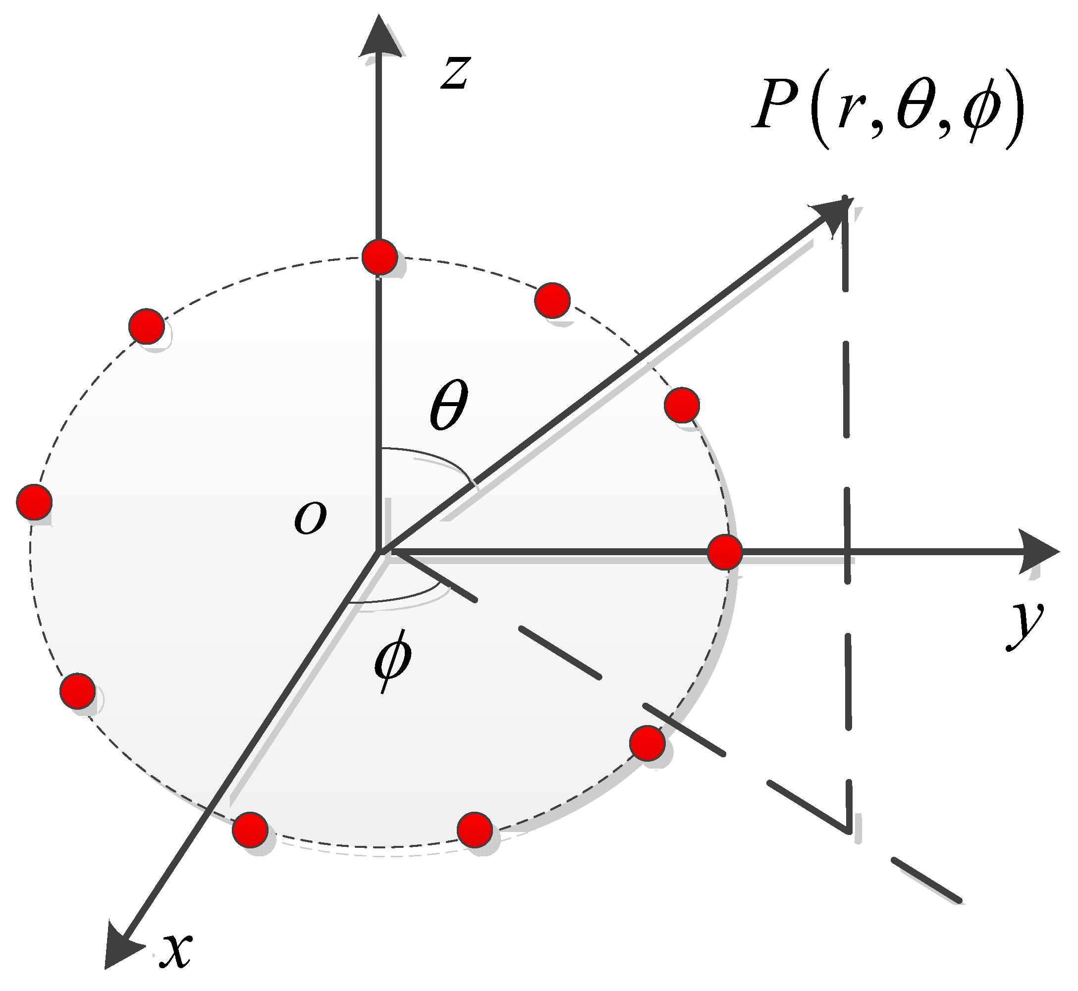
The VEW is usually generated by a circular array.
Figure 1 shows a circular array configuration. Consider a circular array of
N antennas placed equidistantly. According to [
6], the transmitted signal of the
nth array element can be given by
where
is time variable,
is the central frequency of the transmitted signal.
is the transmit phase of the
nth element.
is the waveform, which can be linear frequency modulation signal or other types,
is the OAM mode number.
At the receiver, the same phase weights for the transmitter are applied to the target echo. Then, the echo
of the target at an arbitrary point
can be written as
where
where
is the radius of the circular array.
is the reference time delay.
is the backscatter coefficient.
is the speed of light.
,
is the wavelength.
is the relative angle of
nth element to the circle center.
is the Bessel function of the first kind of
l order.
is target pitch angle.
is the relative target vortex azimuth angle difference.
is the angular speed of the target,
is the radial speed,
is the tangential speed. Normally,
,
can be approximated as follows:
After down-conversion and matched filtering, the target echo can be given as follows:
where
is the constant coefficient after matched filtering,
is the response function of matched filtering.
In Equation (6), both the radial and tangential speed can cause phase shifts related to the Doppler effect. Therefore, in VEW radar, the total Doppler phase shift
is composed of two parts and is given by
From Equation (7), we can see that the first term is the conventional Doppler phase caused by radial movement. The second term is related to tangential speed. It can be seen that the two Doppler effects are coupled in the VEW case. Moreover, the tangential Doppler effect is in inverse proportion to the range. The ratio of the two parts can be given by
The ratio
p is proportional to the range, as shown in Equation (8).
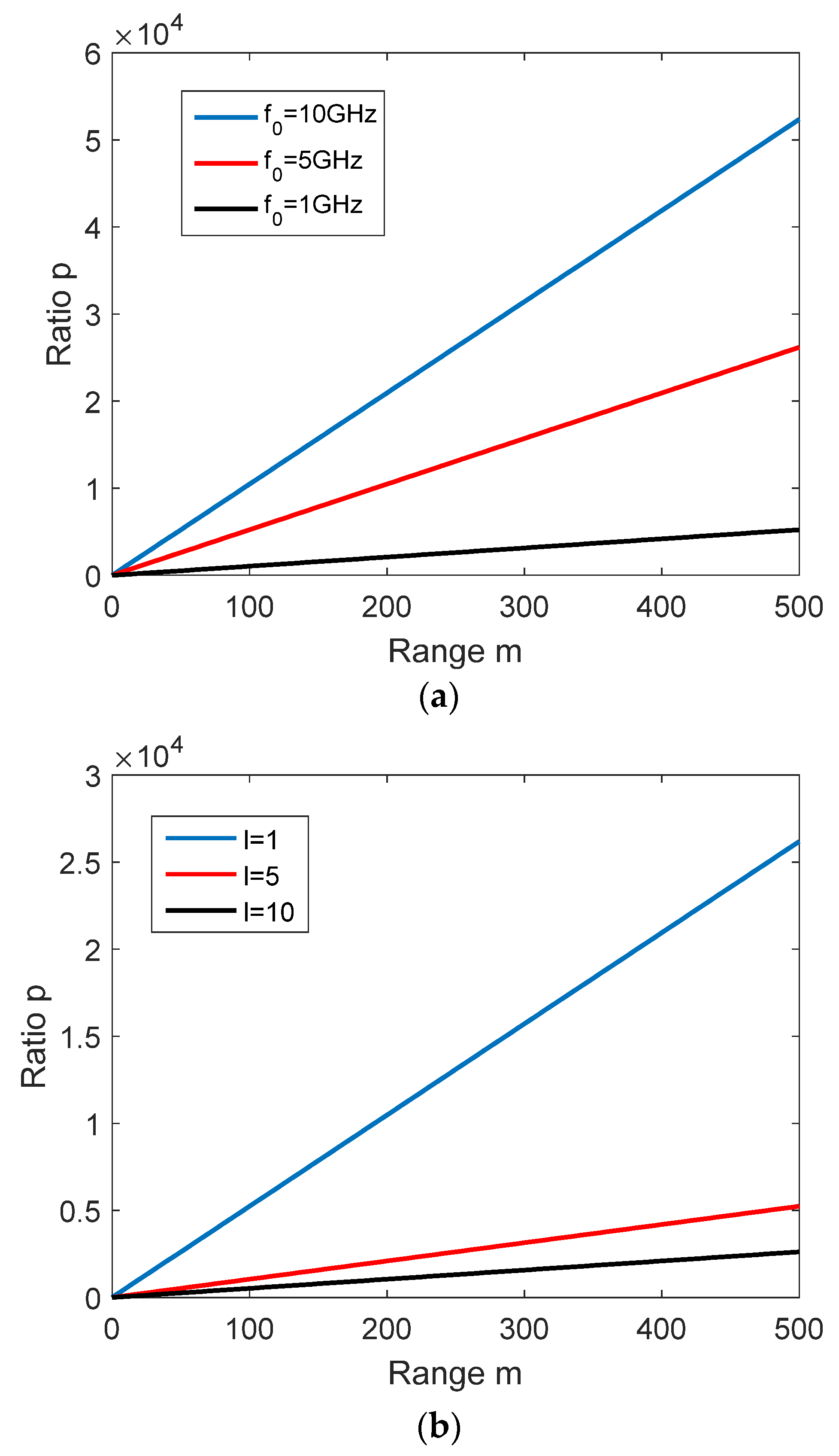
Figure 2 shows the ratio
p curves versus range under different parameters. In both figures,
.
in
Figure 2a.
in
Figure 2b. From
Figure 2a,b, it can be seen that in both cases, an increase in the range leads to a higher value of the ratio
p. In detail, ratio
p is over 50 for a range larger than 100 m in both cases. Apparently, the tangential Doppler phase is much smaller relatively than the radial Doppler phase. Therefore, a higher Doppler frequency resolution is required to estimate tangential Doppler frequency. To estimate the two Doppler frequency components separately, a method based on pulse modulation and modified RFT is proposed in
Section 3.
3. Methods
In
Section 2, the Doppler phase shift of VEW has been shown. Since the two Doppler phase components are coupled, moving target detection (MTD) cannot obtain the true value of the speed information.
A pulse sequence with a different OAM mode was designed to achieve decoupled Doppler estimation. The Doppler shift of VEW is shown in Equation (7). Apparently, the corresponding Doppler frequency can be expressed as follows:
In the equation above, only the second term is related to the OAM mode. Hence, by adjusting the OAM mode, the tangential Doppler frequency changes while the radial Doppler frequency maintains the same value. As shown in
Figure 3, in the proposed design, radar transmits two OAM modes
and
, in turn, pulse-by-pulse. At the receiver, the echoes of two modes are separated from each other in the pulse sequence. Therefore, two sequences having different tangential Doppler frequencies and the same radial Doppler frequency can be obtained. The signal of the two OAM modes can be written as follows:
where
is the pulse repetition time (PRT).
Then, the coupled Doppler frequency of each sub-sequence was estimated. It has been shown that tangential Doppler frequency is relatively small. To extract this Doppler component, a long observation time is required. However, it has been shown that a long observation time can cause a range migration effect [
26,
27]. Conventional time–frequency analysis approaches are invalid under range migration. To overcome this problem, a modified Radon–Fourier transformation is proposed. The original RFT is shown as follows:
where
As shown above, the filter function
is only related to the radial speed in the RFT procedure. However, the Doppler frequency is a combination of tangential and radial Doppler effects when VEW is used. The filter function
should be able to compensate for the coupled Doppler frequency effect. To overcome this problem, the modified filter function
is proposed, which is shown as
where
is the filter function of the modified RFT,
is the compound Doppler frequency.
Since tangential speed is irrelevant to the target range change, a range gate number search in modified RFT remains in the same form of the RFT. Then, the modified RFT results of a pulse sequence are given by
Compared with the current method for VEW Doppler estimation, it can be seen that the range migration phenomenon was considered in our method, which is ignored in previous work. What is more, a modified RFT with VEW fitted filter function is proposed since the original filter function only considers the radial speed. It should be noted that the searching parameter
is aimed at obtaining the true target range position in the observation time. In other words,
is the component of
that can cause range migration. Hence, the searching interval of
is the minimum velocity that can cause range migration which is determined as
where
T is the observation time, and
B is the bandwidth.
By searching three-dimensional space
, the coupled Doppler frequency estimations results can be obtained. Based on Equation (9), the relationships between the estimated results and velocities are shown as follows:
The radial and tangential speed can be estimated by solving the binary linear equation set, which is given by
Nevertheless, a low pulse repetition frequency (PRF) should be used to reduce the calculation quantity in the modified RFT. Since the maximum unambiguous speed (MUS) is low when a low PRF is applied, a radial velocity ambiguity might occur in the decoupling procedure [
28]. In the signal processing procedure, if
, when estimated by the modified RFT is larger than MUS, radial velocity ambiguity happens. To solve the ambiguity, the ambiguity number
should be calculated based on MUS and
which is given by
where
is the MUS of each OAM mode,
is the round toward zero function.
Then, the real radial velocity
can be obtained by
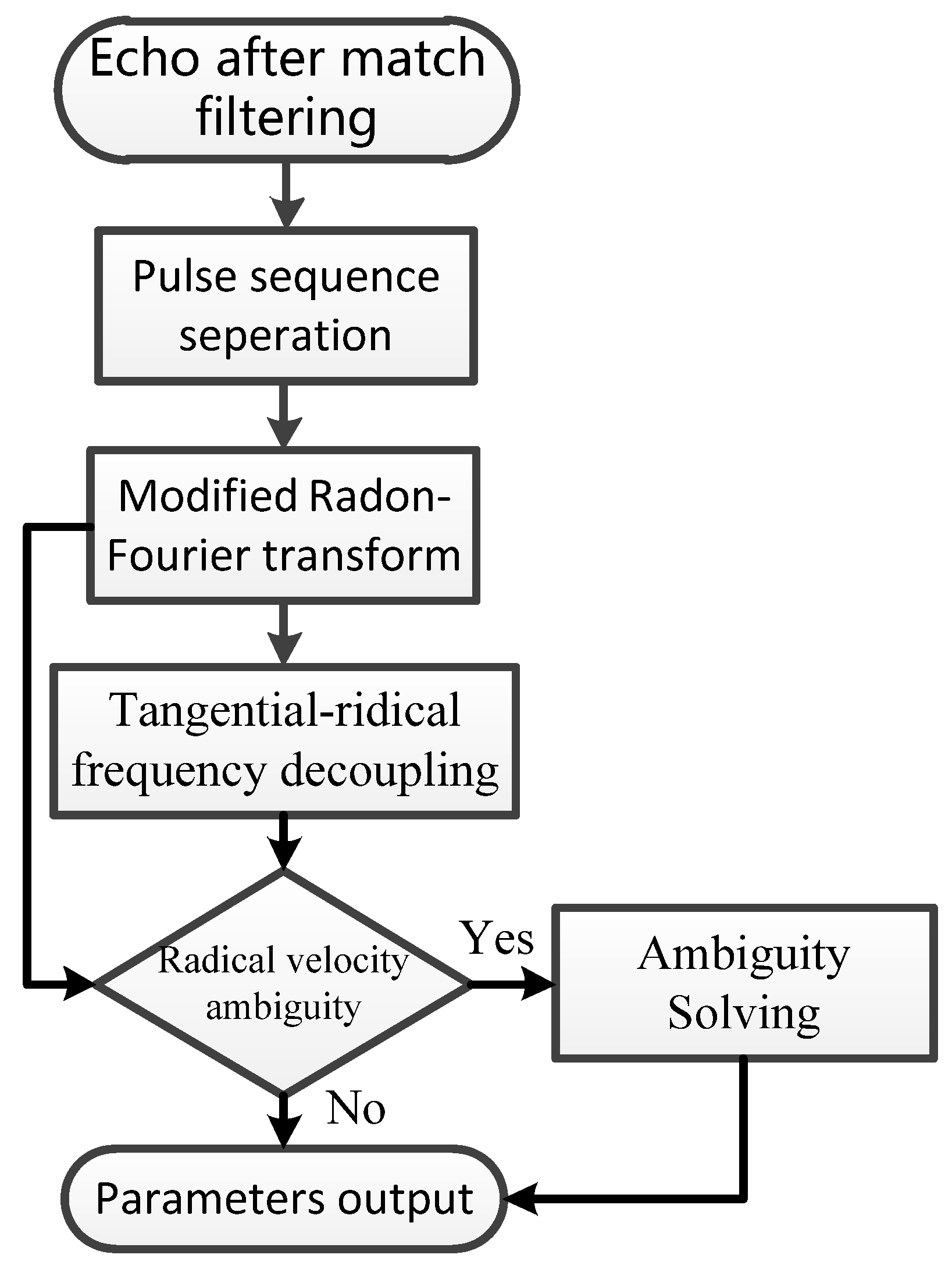
As shown in
Figure 4, the process of the method contains the following steps:
- (1)
The echo after matched filtering is first separated into two sub-pulse sequences with different OAM modes
- (2)
Modified RFT is applied to each sequence.
- (3)
The decoupling procedure calculates velocities.
- (4)
The radial speed estimated in modified RFT is used to judge the radial velocity ambiguity. If ambiguity occurs, the true value is obtained by the ambiguity solving procedure.
Moreover, to improve the performance of the method, a big difference between the compound Doppler frequencies of the two OAM modes is required. Therefore, according to Equation (9), the difference between the two modes should be as big as possible. In addition, when multiple OAM modes are used, several sets with different combinations of OAM modes can be built. By using the mean value of the estimation results of all sets, the overall estimation error is reduced.
4. Simulation Results
The performance of the proposed 2-D velocity estimation method is further verified in this section. In the first simulation experiments, the carry frequency was set to 10 GHz,
l = 3. The VEWs were generated based on the circular array configuration shown in
Figure 1. As shown in [
6], the antenna number
N should be more than 2 times larger than
l. When
, the VEW’s performance was robust against noise. Therefore, 16 antenna elements were placed equidistantly in the simulation. The Doppler frequency versus range curves of different radial speeds
and tangential speeds
are shown in
Figure 5. Apparently, the radial Doppler frequency is irrelevant to range. However, the tangential Doppler frequency decreased while range increased. The variation changed a lot when the range was shorter than 100 m. On the other hand, with a longer distant, the tangential Doppler frequency’s variation could be ignored. By comparing the frequency value of same range in
Figure 5a,b, it can be seen that the radial Doppler frequency was much higher than the tangential Doppler frequency when the range was longer than 400 m, which fit the analyses in
Section 2. Hence, unlike the conventional Doppler estimation procedure, a long observation time was required to obtain a 2D velocity estimation in VEW radar.
The second experiment considered the Doppler estimation performance of the modified RFT. Radar parameters are shown in
Table 1. The array configuration was the same as in the first experiment. The radar transmitted the two OAM modes in turn pulse-by-pulse. In the next simulation, a target with motion parameters of
,
and original range
was simulated. The signal to noise ratio (SNR) before the matched filter was 0 dB.
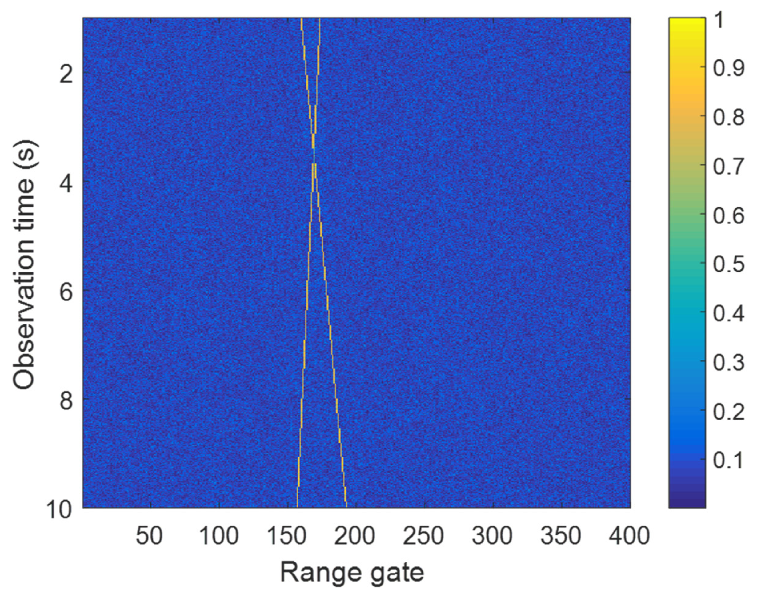
Figure 6 shows the image of signal in the time–range plane after matched filtering. From
Figure 6, it can be seen that range migration occurred with a long observation time. In this case, the method in [
20,
21,
22,
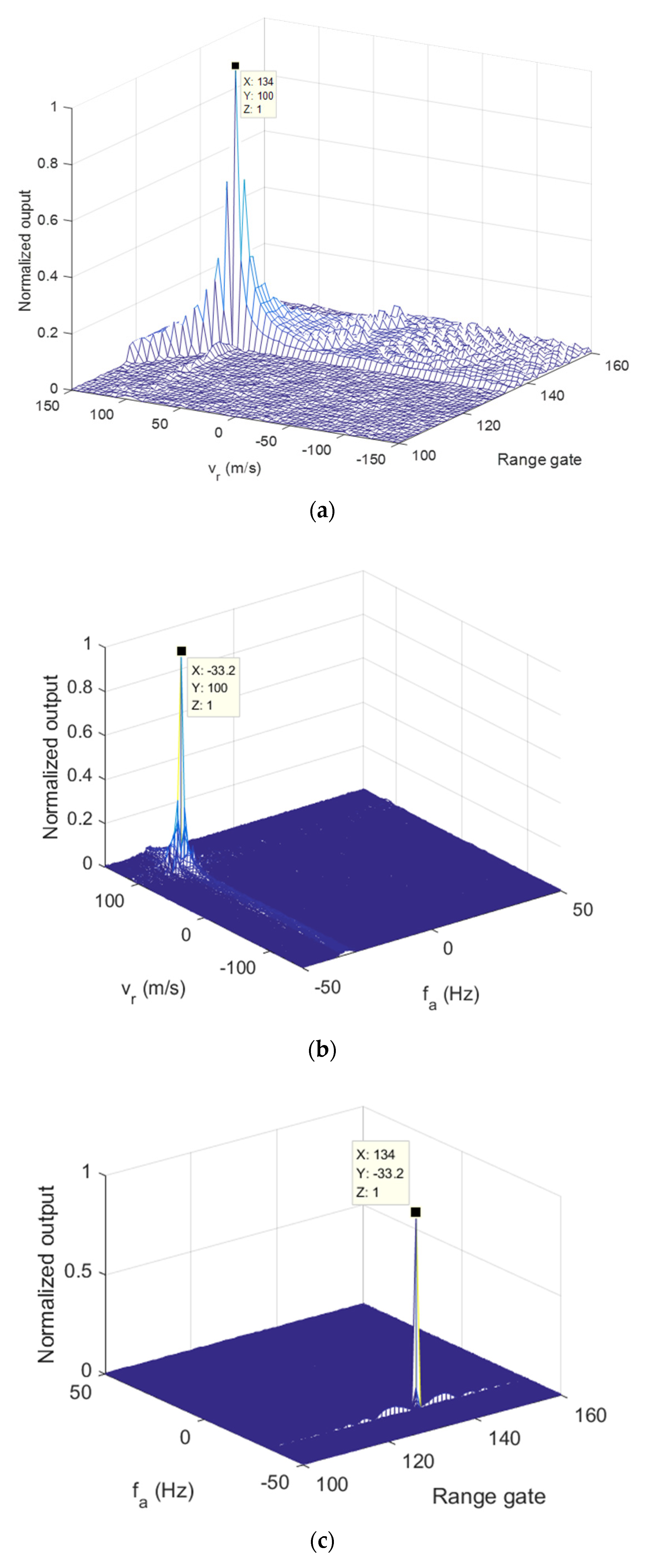
23] cannot achieve Doppler estimation effectively. Then, the two pulse sequences with different OAM mode were separated. In
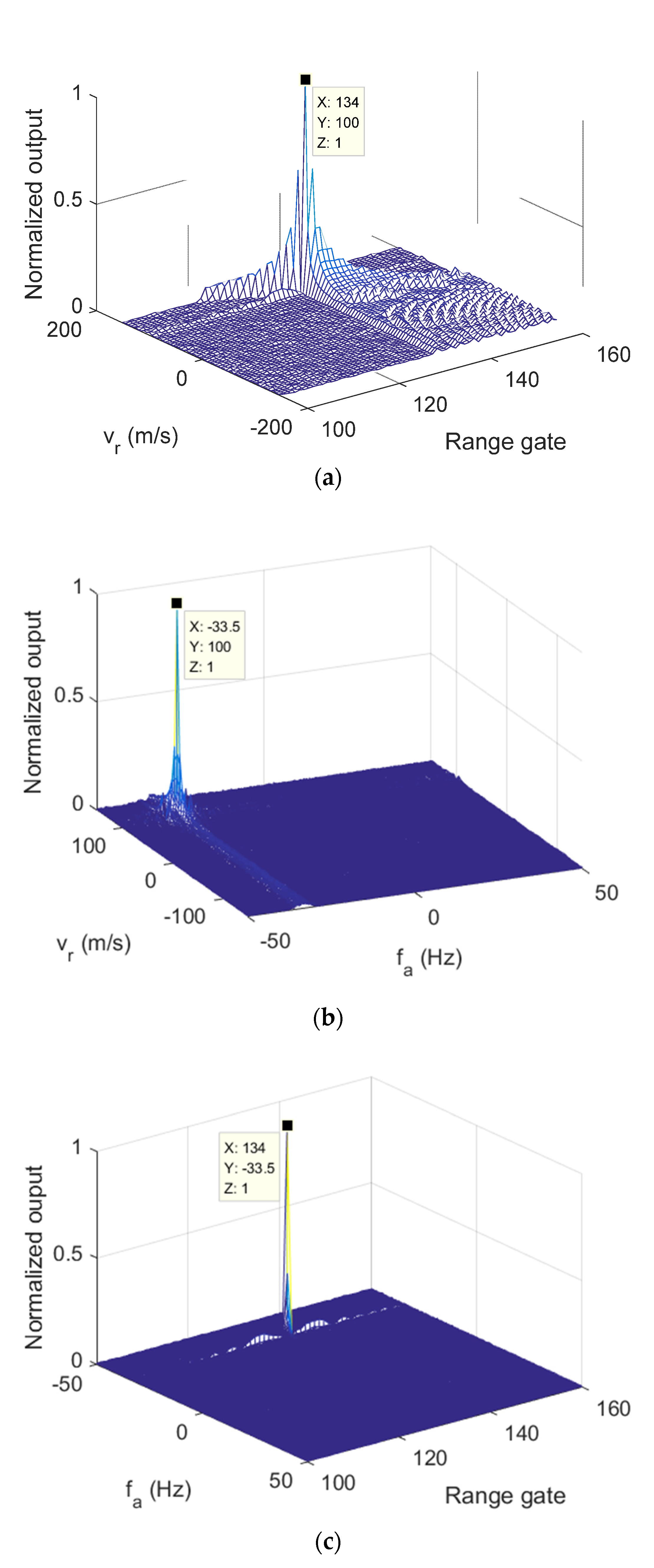
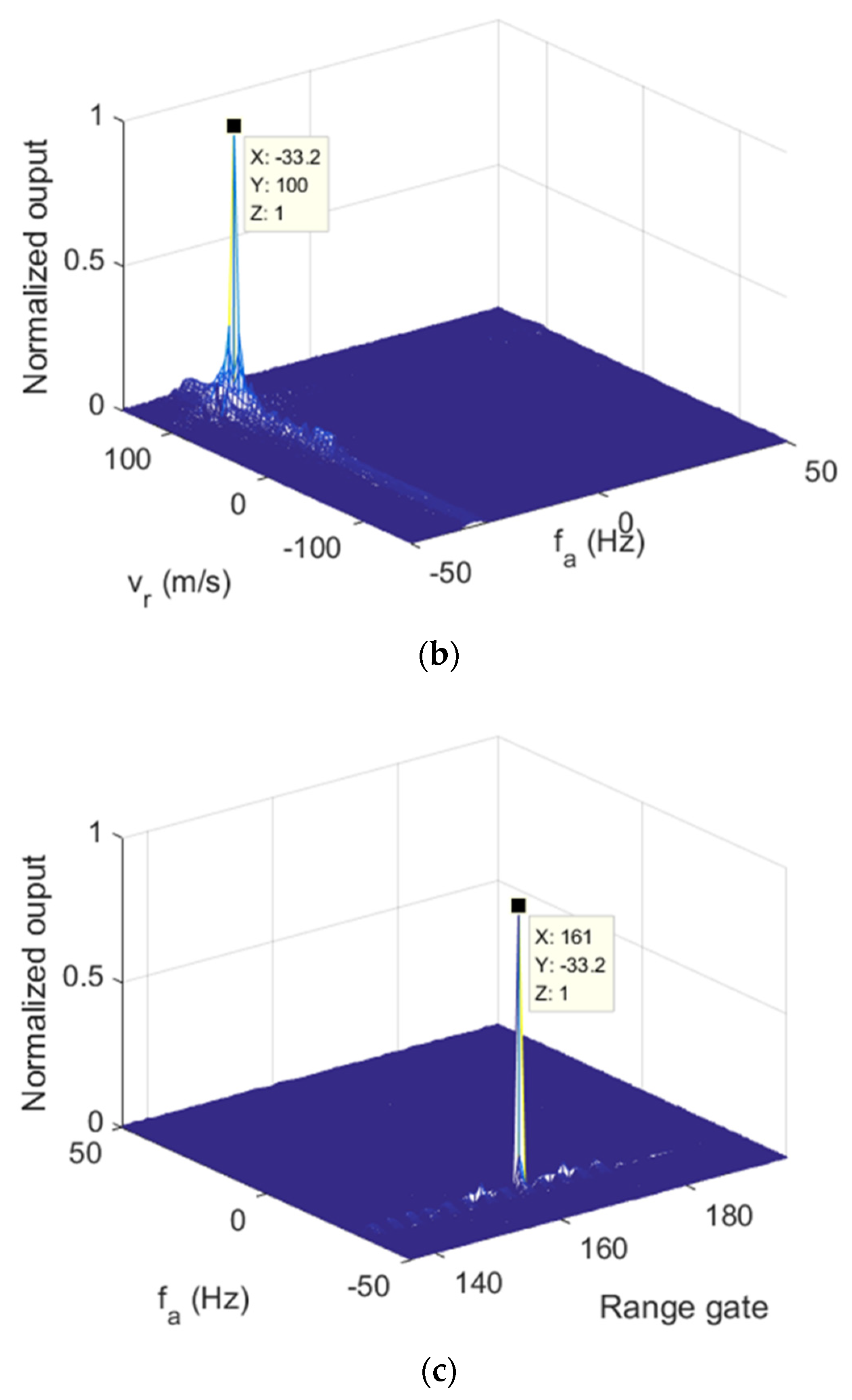
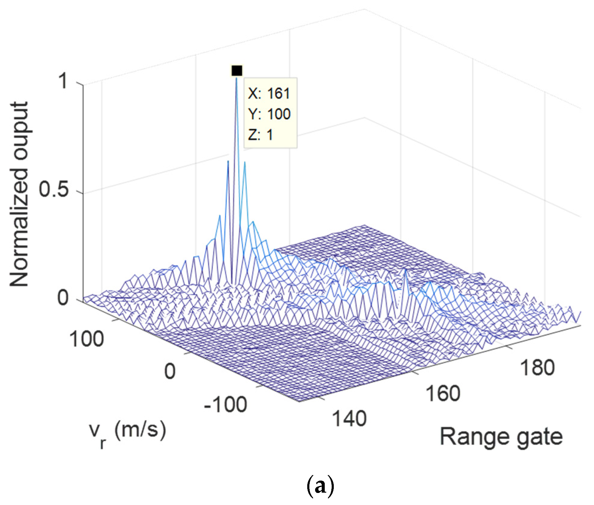
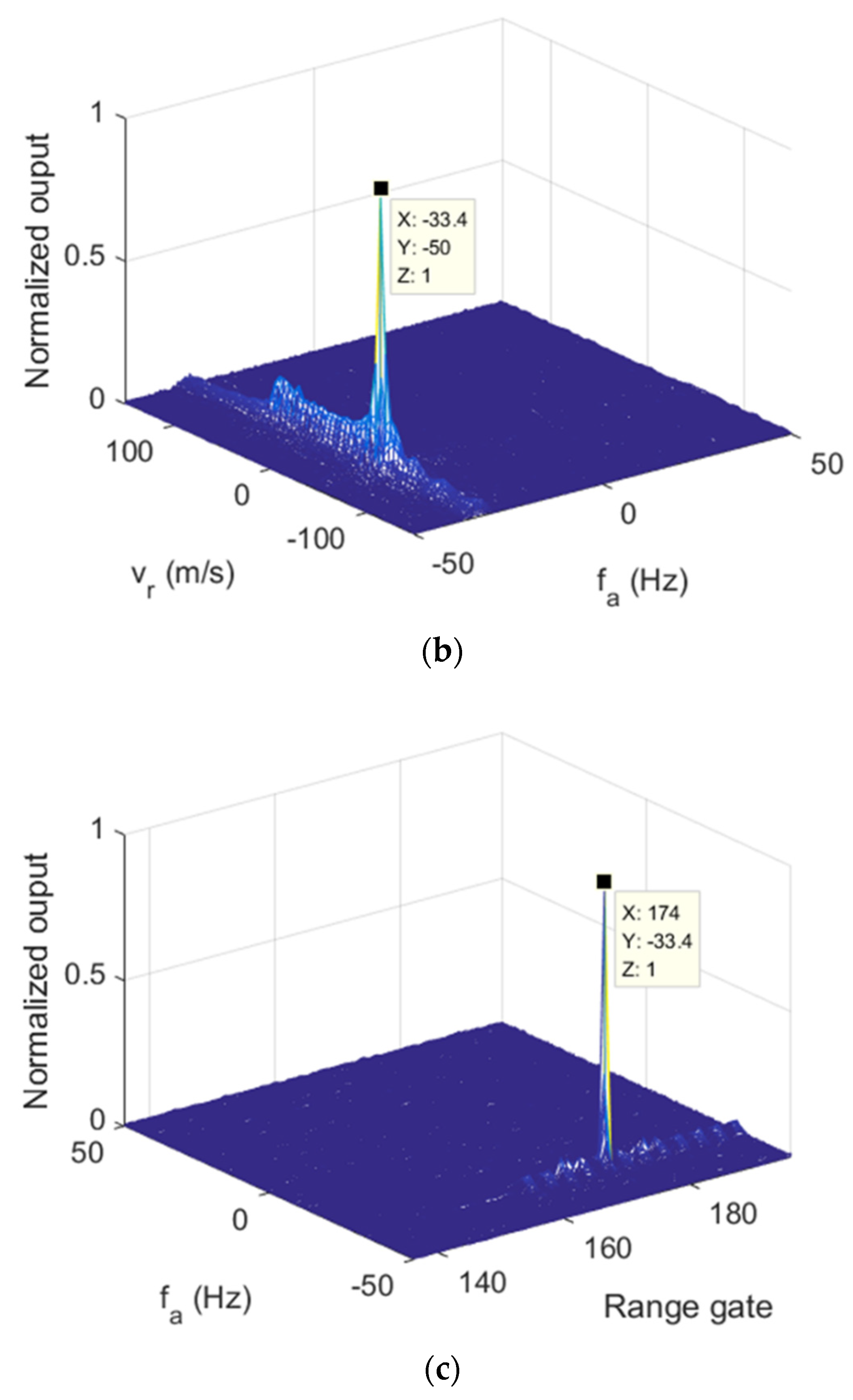
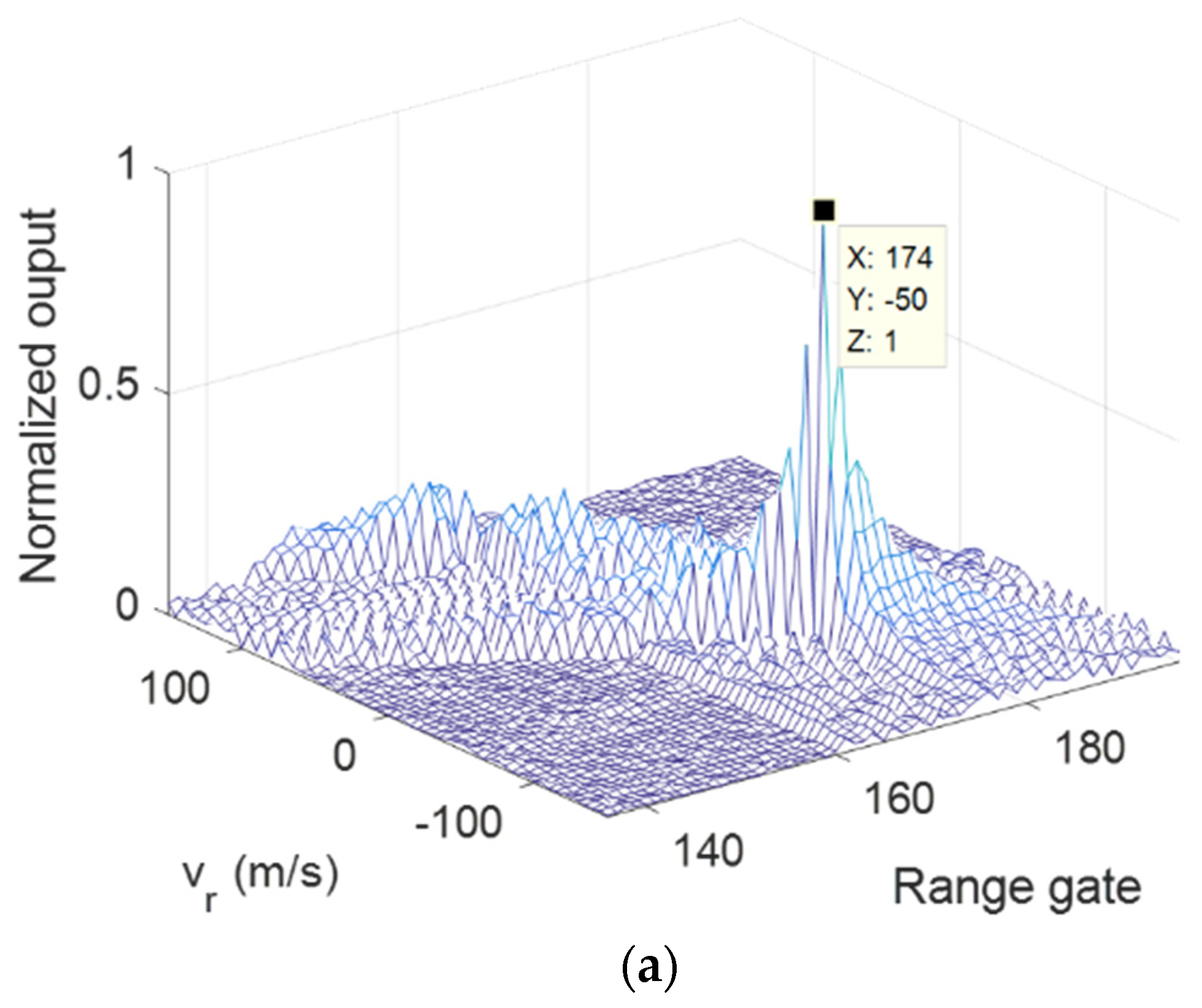
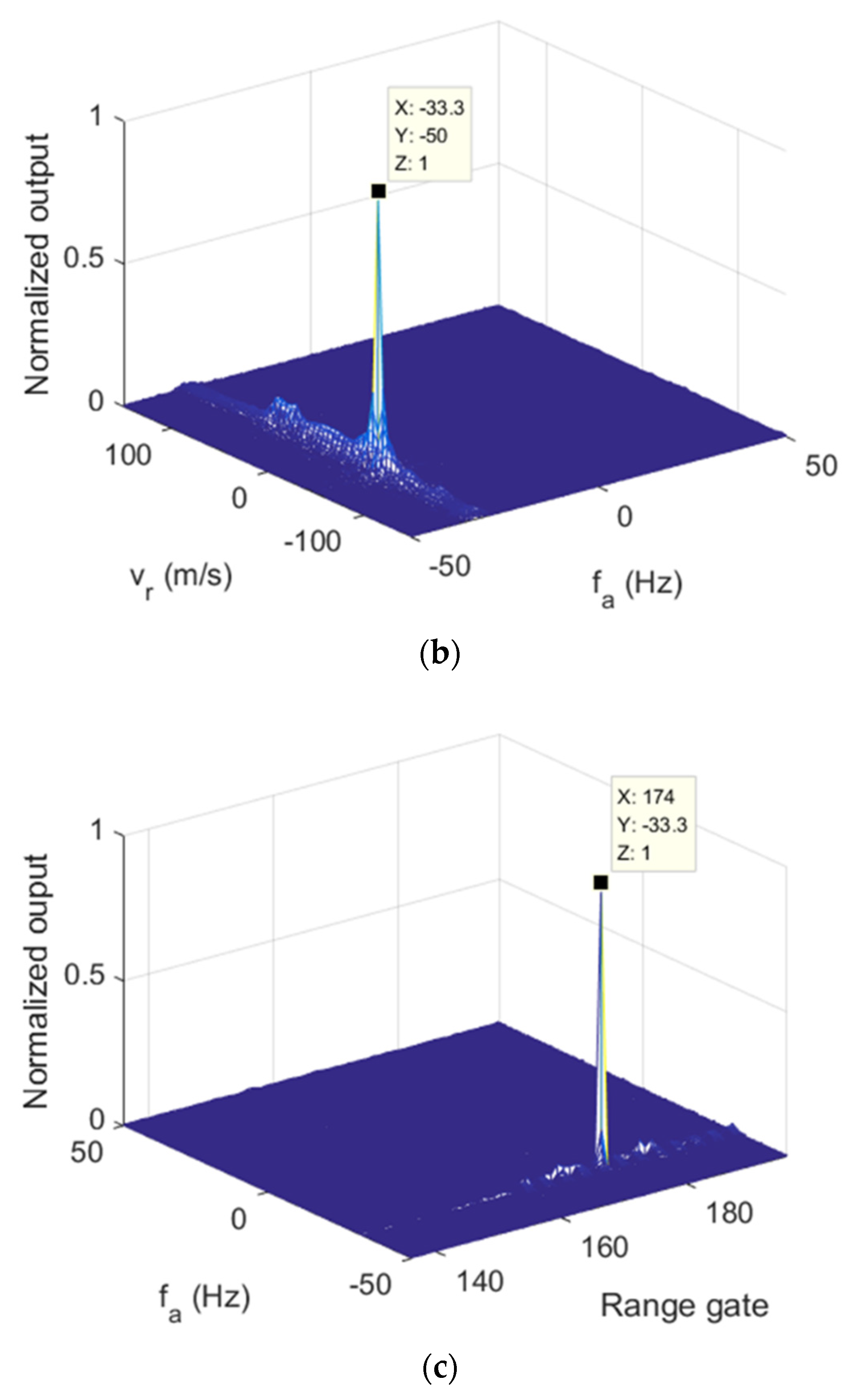
Figure 7, the three 2D sections of modified RFT results of
are given. The target parameters were clearly estimated after applying the modified RFT. Similar performances can be found in
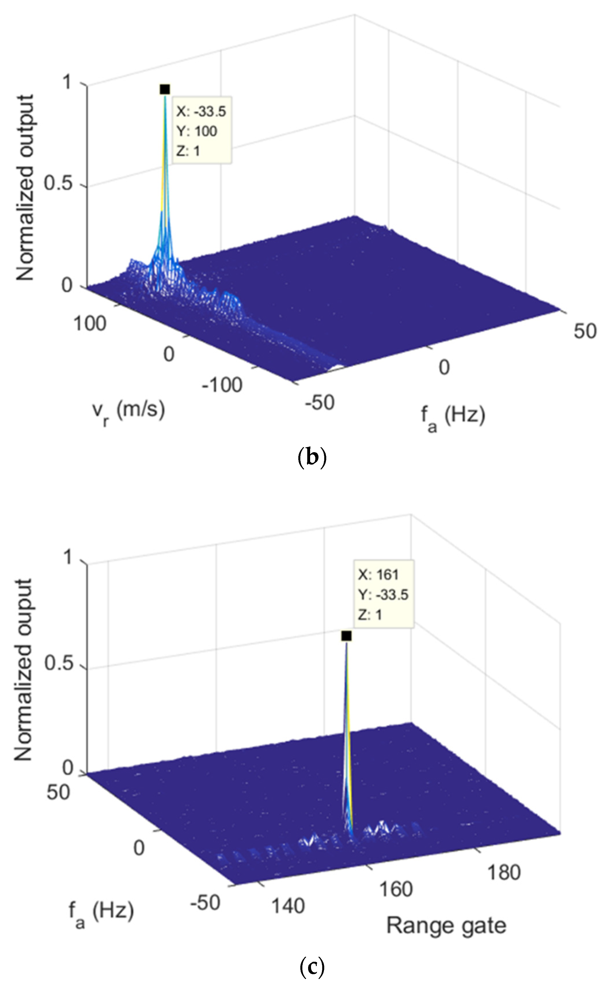
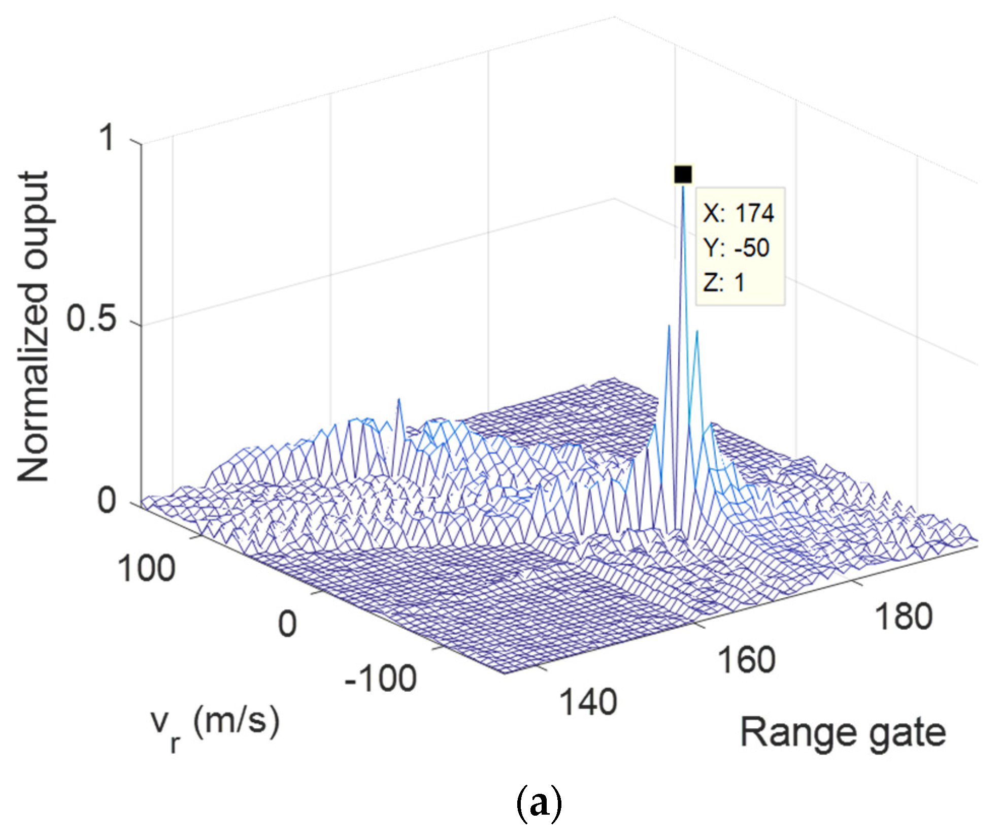
Figure 8, which presents the modified RFT results of
.
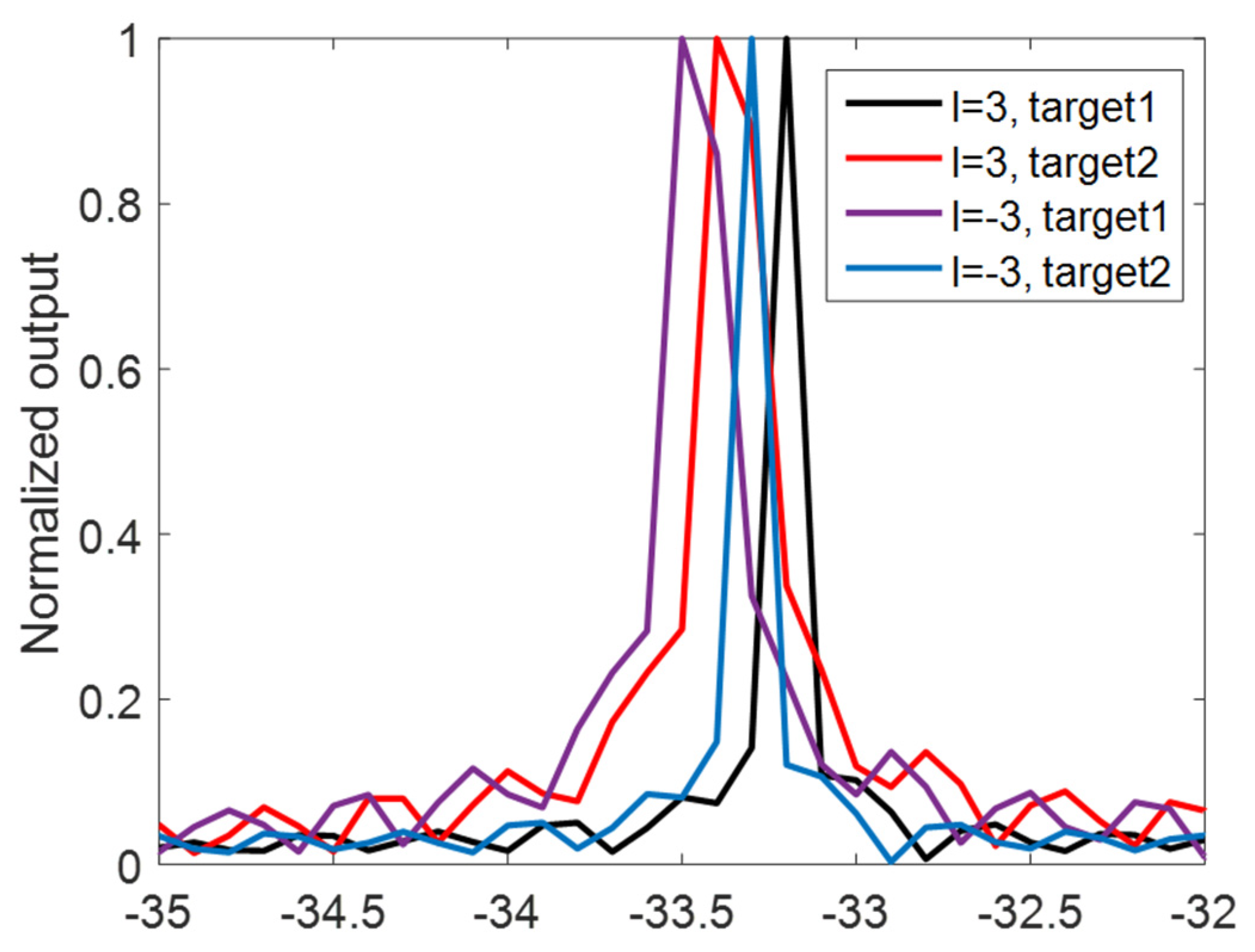
Moreover, to decouple the combined Doppler frequency, the pulse-by-pulse strategy shown in
Section 3 was applied. Based on results of the modified RFT under
l1 = −3,
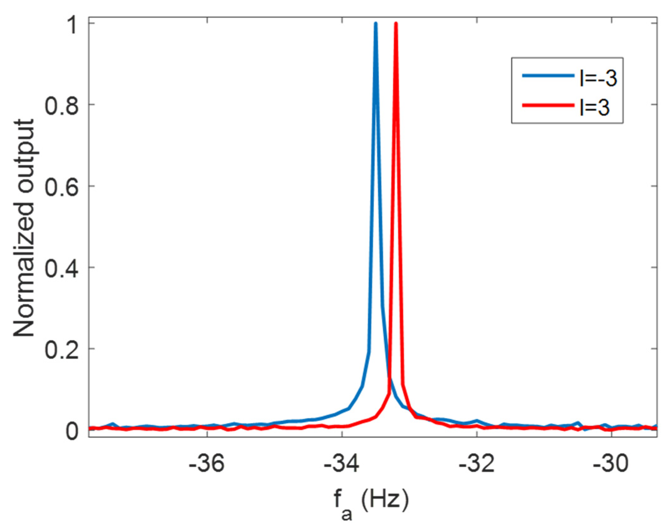
l2 = −3, the Doppler frequency estimations of the target could be extracted, which are shown in
Figure 9. The Doppler frequency estimations were different since the OAM mode changed. By substituting the estimation results into Equation (18), the tangential and radial speed were calculated as 315.73 m/s and −0.503 m/s. With the parameters in
Table 1, the MUS in the modified RFT procedure was 1.5 m/s, which was much smaller than the radial velocity estimations of modified RFT. It means that velocity ambiguity happened. Then, the true value was obtained by the ambiguity solving procedure, which was 99.997 m/s. Moreover, the estimation errors of tangential and radial speed were 5.24% and 0.003%. To improve the tangential velocity estimation performance, the Doppler frequency resolution should be improved which means longer observation time is required. In addition, by increasing the mode difference between the two OAM mode, the tangential Doppler frequency difference increases so that the performance can be improved with same Doppler frequency resolution. Therefore, both a longer observation time and bigger OAM mode difference lead to better estimation performance.
The multiple target performance was tested in the next simulation. Radar parameters remained the same as in
Table 1. The targets’ parameters are shown in
Table 2.
Figure 10 shows the signal in time–range plane after matched filtering of multiple targets. Two oblique lines are shown in the figure which means range migration happened for both targets within the observation time.
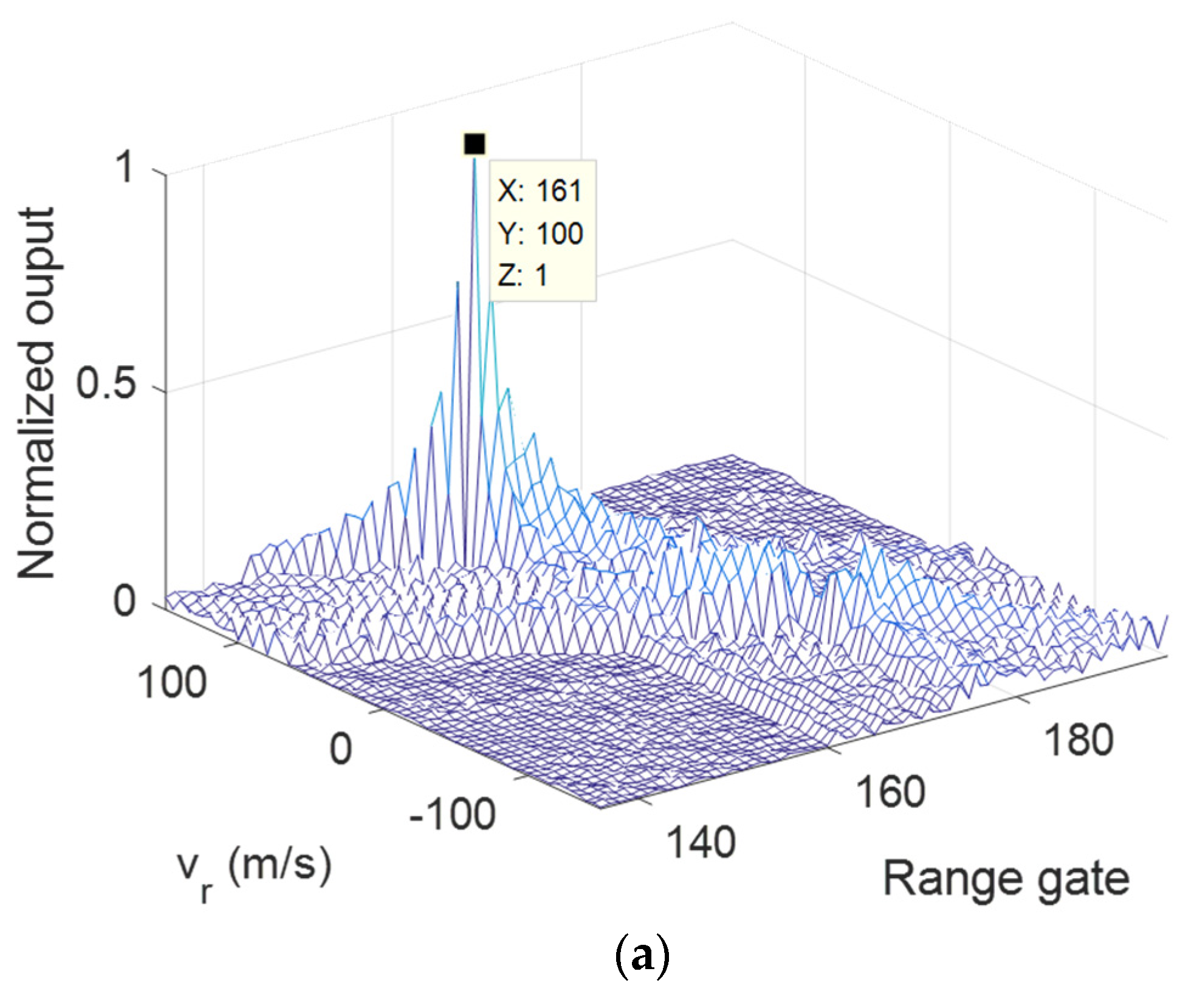
The modified RFT results of Target 1 under
,
are given in
Figure 11 and
Figure 12. It can be seen that the parameters of Target 1 were successfully estimated in both OAM modes. Similar performance can be obtained in
Figure 13 and
Figure 14, which show the results of Target 2. For both targets, the sidelobe in the
—range plane was higher than single target case, which was caused by the mutual interference.
Figure 15 shows the Doppler frequency estimations of the targets. The calculated velocities and estimation errors after ambiguity solving are shown in
Table 3. Obviously, the estimation errors of the radial and tangential speed varied significantly. The reason for this phenomenon is that radial Doppler frequency is much higher than tangential Doppler frequency with same radar parameters, so under the same Doppler frequency resolution, better estimation can be achieved for radial Doppler frequency. In addition, it can be seen that the tangential estimation error increased notably when the tangential speed was low. To improve the performance, a higher Doppler frequency resolution is required, which leads to a longer observation time.
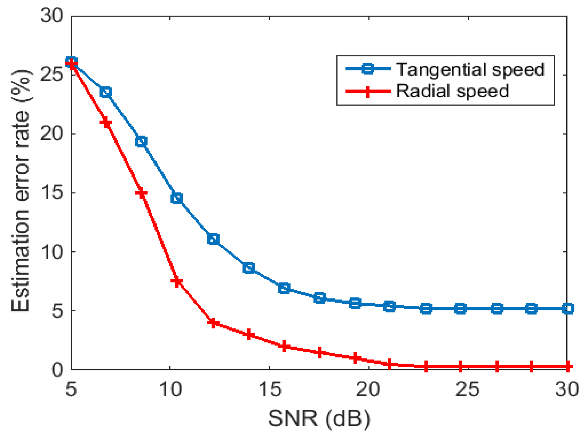
The next simulation considered the influence of noise to the estimation results. The target’s motion and radar parameters were the same as in the second experiment. The estimation error rate versus SNR after modified RFT is shown in
Figure 16. It can be seen that higher SNR led to better estimation results. However, when SNR was high enough, the estimation error remained the same. In this case, to reduce estimation error, a better Doppler frequency resolution should be provided.
