
A Joint Estimation Method of the Channel Phase Error and Motion Error for Distributed SAR on a Single Airborne Platform Based on a Time-Domain Correlation Method

Abstract
:1. Introduction
2. Signal Model
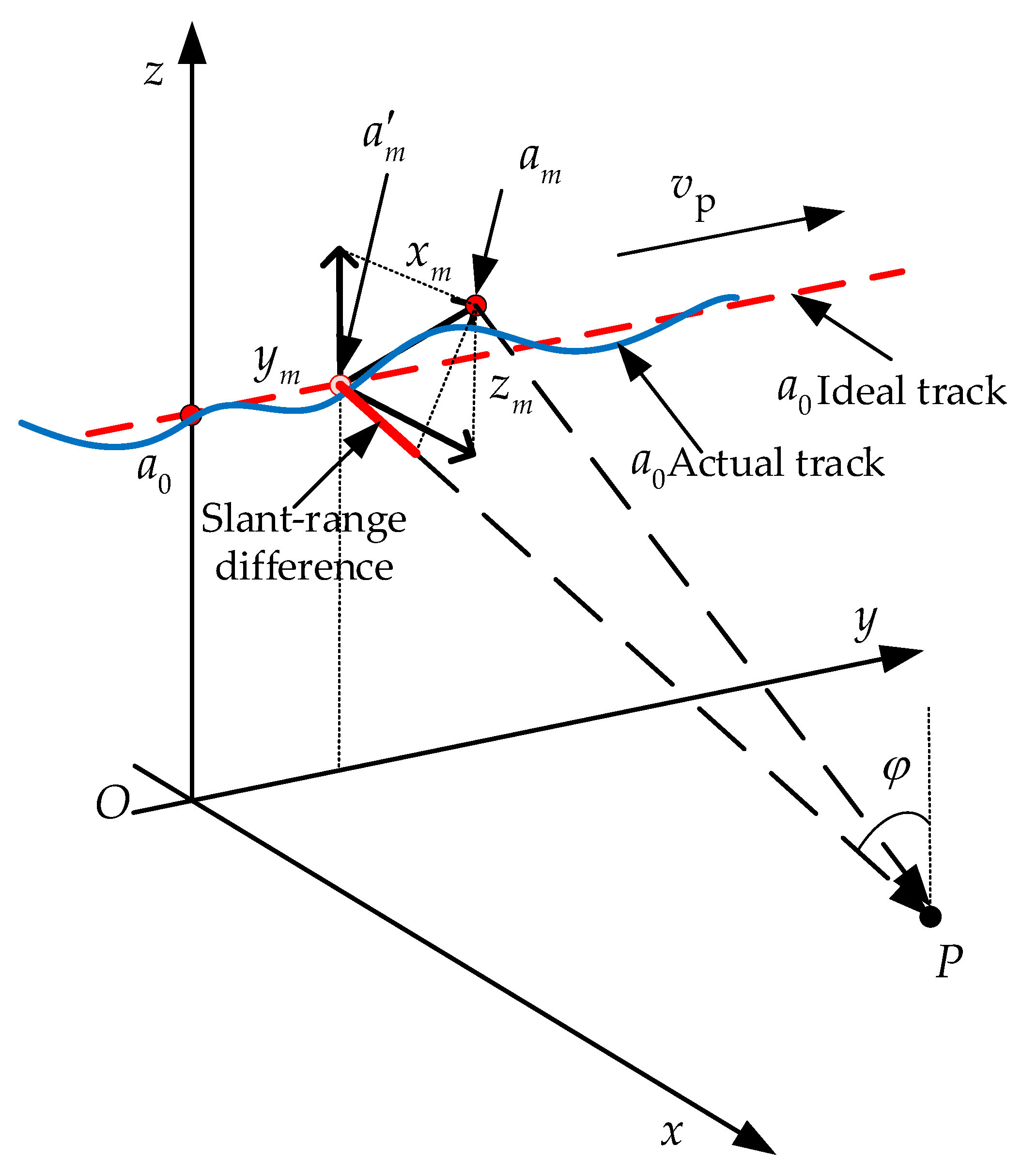
2.1. The Geometry of Distributed SAR
2.2. Mathematical Model
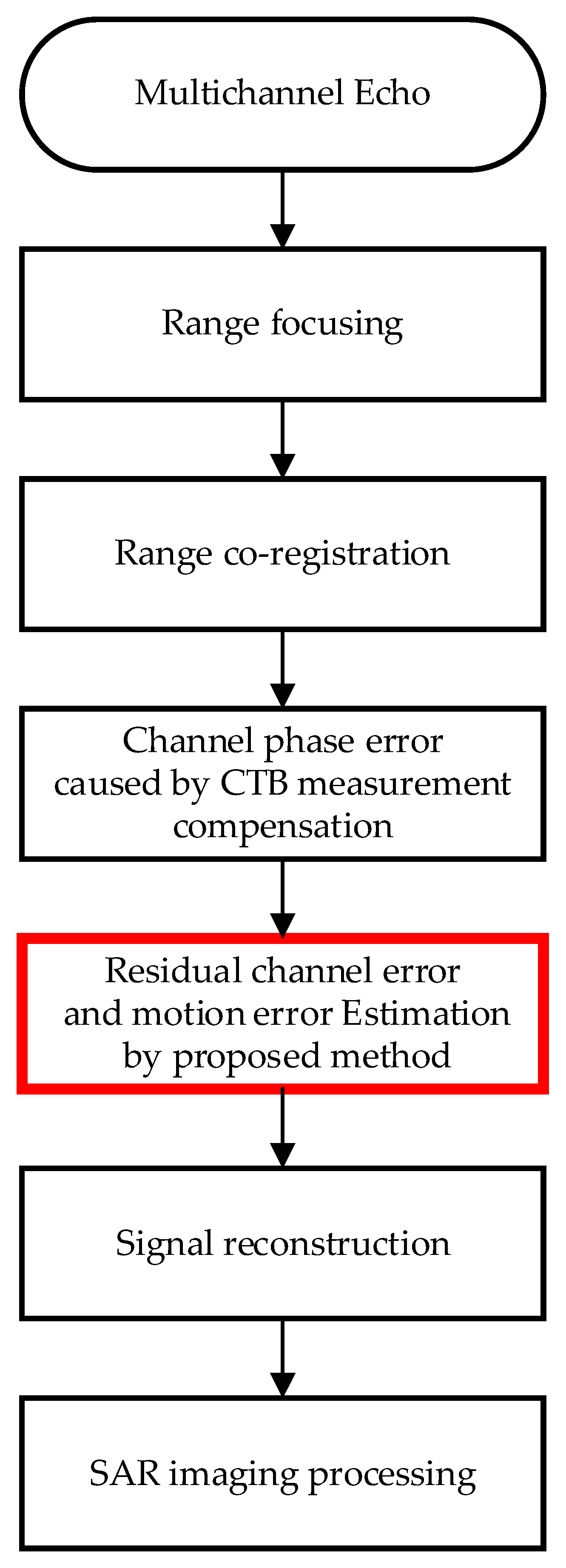
3. Processing Method
3.1. Processing Flow
3.2. The Proposed Method
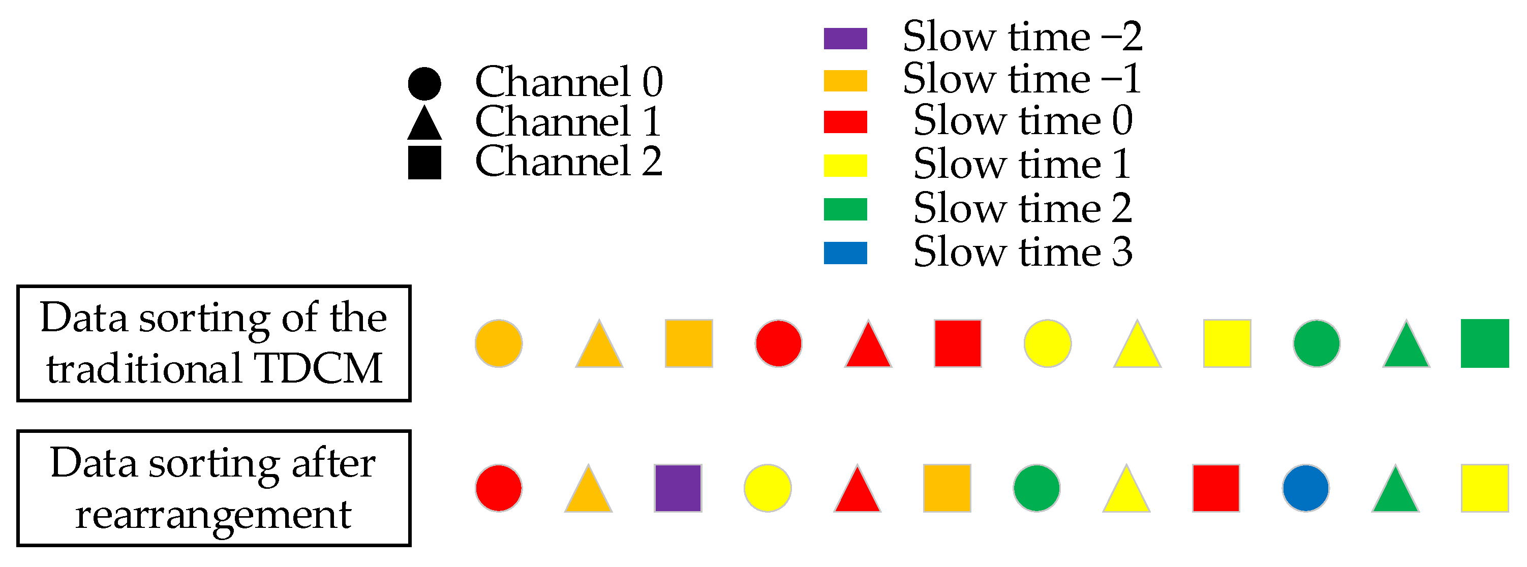
3.2.1. Data Rearrangement
3.2.2. TDCM Processing
3.2.3. Radial Acceleration Estimation
3.2.4. Signal Phase Error Compensation
4. Result of the Experiment and Discussion
4.1. Signal Error Estimation Simulation
4.2. Scene Imaging Simulation
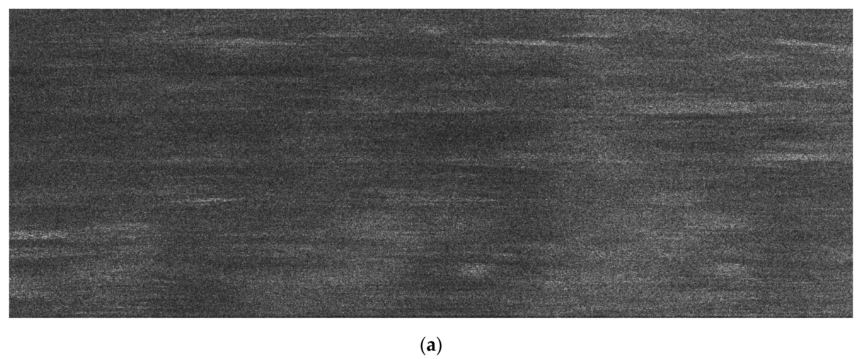
4.3. Real Data Processing
5. Conclusions
Author Contributions
Funding
Conflicts of Interest
References
- Gebert, N. Multi-Channel Azimuth Processing for High-Resolution Wide-Swath SAR Imaging; DLR (German Aerospace Center): Cologne, Germany, 2009. [Google Scholar]
- Xu, H.; Yang, Z.; Tian, M.; Sun, Y.; Liao, G. An Extended Moving Target Detection Approach for High-Resolution Multichannel SAR-GMTI Systems Based on Enhanced Shadow-Aided Decision. IEEE Trans. Geosci. Remote Sens. 2018, 56, 715–729. [Google Scholar] [CrossRef]
- Toporkov, J.V. A Theoretical Study of Velocity SAR Imaging of a Moving, Nonstationary Scene. IEEE Trans. Geosci. Remote Sens. 2017, 55, 4972–4988. [Google Scholar] [CrossRef]
- Currie, A.; Brown, M.A. Wide-swath SAR. IEE Proc. F Radar Signal Process. 1992, 139, 122–135. [Google Scholar] [CrossRef]
- Ferraioli, G.; Deledalle, C.-A.; Denis, L.; Tupin, F. Parisar: Patch-based estimation and regularized inversion for multibaseline SAR interferometry. IEEE Trans. Geosci. Remote Sens. 2017, 56, 1626–1636. [Google Scholar] [CrossRef] [Green Version]
- Krieger, G.; Fiedler, H.; Moreira, A. Bi-and multistatic SAR: Potentials and challenges. In Proceedings of the European Conference on Synthetic Aperture Radar (EUSAR), Ulm, Germany, 25–27 May 2004; pp. 365–369. [Google Scholar]
- Krieger, G.; Moreira, A. Spaceborne bi-and multistatic SAR: Potential and challenges. IEE Proc. Radar Sonar Navig. 2006, 153, 184–198. [Google Scholar] [CrossRef] [Green Version]
- Massonnet, D. Capabilities and limitations of the interferometric cartwheel. IEEE Trans. Geosci. Remote Sens. 2001, 39, 506–520. [Google Scholar] [CrossRef]
- Moccia, A.; Rufino, G.; D’Errico, M.; Alberti, G.; Salzillo, G. BISSAT: A bistatic SAR for earth observation. In Proceedings of the IEEE International Geoscience and Remote Sensing Symposium, Toronto, ON, Canada, 24–28 June 2002; pp. 2628–2630. [Google Scholar]
- Moreira, A.; Krieger, G.; Hajnsek, I.; Hounam, D.; Werner, M.; Riegger, S.; Settelmeyer, E. TanDEM-X: A TerraSAR-X add-on satellite for single-pass SAR interferometry. In Proceedings of the IGARSS 2004 IEEE International Geoscience and Remote Sensing Symposium, Anchorage, AK, USA, 20–24 September 2004; pp. 1000–1003. [Google Scholar]
- Kraus, T.; Krieger, G.; Bachmann, M.; Moreira, A. Spaceborne demonstration of distributed SAR imaging with TerraSAR-X and TanDEM-X. IEEE Geosci. Remote Sens. Lett. 2019, 16, 1731–1735. [Google Scholar] [CrossRef]
- Lou, S.; Liu, Z.; Zhang, H.; Qian, F.; Huang, Y. TH-2 satellite engineering design and implementation. Acta Geod. Cartogr. Sin. 2020, 49, 1252–1264. [Google Scholar] [CrossRef]
- Li, Z.; Bao, Z.; Wang, H.; Liao, G. Performance improvement for constellation SAR using signal processing techniques. IEEE Trans. Aerosp. Electron. Syst. 2006, 42, 436–452. [Google Scholar]
- Liu, A.; Liao, G.; Ma, L.; Xu, Q. An array error estimation method for constellation SAR systems. IEEE Geosci. Remote Sens. Lett. 2010, 7, 731–735. [Google Scholar] [CrossRef]
- Liu, A.; Liao, G.; Xu, Q.; Ma, L. An improved array-error estimation method for constellation SAR systems. IEEE Geosci. Remote Sens. Lett. 2011, 9, 90–94. [Google Scholar] [CrossRef]
- Zhang, S.-X.; Xing, M.-D.; Xia, X.-G.; Liu, Y.-Y.; Guo, R.; Bao, Z. A robust channel-calibration algorithm for multi-channel in azimuth HRWS SAR imaging based on local maximum-likelihood weighted minimum entropy. IEEE Trans. Image Process. 2013, 22, 5294–5305. [Google Scholar] [CrossRef] [PubMed]
- Kraus, T.; Bachmann, M.; Heiderich, L.; Krieger, G.; Moreira, A. Multistatic SAR imaging: Comparison of simulation results and experimental data. In Proceedings of the International Conference on Radar Systems (Radar 2017), Belfast, UK, 23–26 October 2017; pp. 1–5. [Google Scholar]
- Gebert, N.; Krieger, G.; Moreira, A. Digital beamforming on receive: Techniques and optimization strategies for high-resolution wide-swath SAR imaging. IEEE Trans. Aerosp. Electron. Syst. 2009, 45, 564–592. [Google Scholar] [CrossRef] [Green Version]
- Freeman, A.; Johnson, W.T.K.; Huneycutt, B.; Jordan, R.; Hensley, S.; Siqueira, P.; Curlander, J. The “Myth” of the minimum SAR antenna area constraint. IEEE Trans. Geosci. Remote Sens. 2000, 38, 320–324. [Google Scholar] [CrossRef] [Green Version]
- Krieger, G.; Gebert, N.; Moreira, A. Unambiguous SAR signal reconstruction from nonuniform displaced phase center sampling. IEEE Geosci. Remote Sens. Lett. 2004, 1, 260–264. [Google Scholar] [CrossRef] [Green Version]
- Cerutti-Maori, D.; Sikaneta, I.; Klare, J.; Gierull, C.H. MIMO SAR processing for multichannel high-resolution wide-swath radars. IEEE Trans. Geosci. Remote Sens. 2013, 52, 5034–5055. [Google Scholar] [CrossRef]
- Sikaneta, I.; Gierull, C.H.; Cerutti-Maori, D. Optimum signal processing for multichannel SAR: With application to high-resolution wide-swath imaging. IEEE Trans. Geosci. Remote Sens. 2014, 52, 6095–6109. [Google Scholar] [CrossRef]
- Zhang, S.-X.; Xing, M.-D.; Xia, X.-G.; Zhang, L.; Guo, R.; Liao, Y.; Bao, Z. Multichannel HRWS SAR imaging based on range-variant channel calibration and multi-Doppler-direction restriction ambiguity suppression. IEEE Trans. Geosci. Remote Sens. 2013, 52, 4306–4327. [Google Scholar] [CrossRef]
- Guo, J.; Zhang, J.; Yang, K.; Zhang, B.; Hong, W.; Wu, Y. Information capacity and sampling ratios for compressed sensing-based SAR imaging. IEEE Geosci. Remote Sens. Lett. 2014, 12, 900–904. [Google Scholar]
- Razzaque, M.A.; Dobson, S. Energy-efficient sensing in wireless sensor networks using compressed sensing. Sensors 2014, 14, 2822–2859. [Google Scholar] [CrossRef] [Green Version]
- Rostami, M.; Cheung, N.-M.; Quek, T.Q.S. Compressed sensing of diffusion fields under heat equation constraint. In Proceedings of the 2013 IEEE International Conference on Acoustics, Speech and Signal Processing, Vancouver, BC, Canada, 26–31 May 2013; pp. 4271–4274. [Google Scholar]
- Kraus, T.; Bräutigam, B.; Bachmann, M.; Krieger, G. Multistatic SAR imaging: First results of a four phase center experiment with TerraSAR-X and TanDEM-X. In Proceedings of the EUSAR 2016: 11th European Conference on Synthetic Aperture Radar, Hamburg, Germany, 6–9 June 2016; pp. 1–5. [Google Scholar]
- Rodriguez-Cassola, M.; Prats-Iraola, P.; Steinbrecher, U.; Schulze, D.; Krieger, G.; Reigber, A.; Moreira, A. Cross-platform spaceborne SAR imaging: Demonstration using TanDEM-X. In Proceedings of the 2013 IEEE International Geoscience and Remote Sensing Symposium-IGARSS, Melbourne, VIC, Australia, 21–26 July 2013; pp. 2962–2965. [Google Scholar]
- Fang, D.; Lv, X.; Yun, Y.; Li, F. An InSAR fine registration algorithm using uniform tie points based on Voronoi diagram. IEEE Geosci. Remote Sens. Lett. 2017, 14, 1403–1407. [Google Scholar] [CrossRef]
- Yague-Martinez, N.; de Zan, F.; Prats-Iraola, P. Coregistration of interferometric stacks of Sentinel-1 TOPS data. IEEE Geosci. Remote Sens. Lett. 2017, 14, 1002–1006. [Google Scholar] [CrossRef] [Green Version]
- Bentoutou, Y.; Taleb, N.; Kpalma, K.; Ronsin, J. An automatic image registration for applications in remote sensing. IEEE Trans. Geosci. Remote Sens. 2005, 43, 2127–2137. [Google Scholar] [CrossRef]
- Fang, C.; Liu, Y.; Suo, Z.; Li, Z.; Chen, J. Improved channel mismatch estimation for multi-channel HRWS SAR based on azimuth cross-correlation. Electron. Lett. 2018, 54, 235–237. [Google Scholar] [CrossRef]
- Liu, Y.-y.; Li, Z.-f.; Yang, T.-l.; Bao, Z. An adaptively weighted least square estimation method of channel mismatches in phase for multichannel SAR systems in azimuth. IEEE Geosci. Remote Sens. Lett. 2013, 11, 439–443. [Google Scholar] [CrossRef]
- Yang, T.; Li, Z.; Liu, Y.; Suo, Z.; Bao, Z. Channel error estimation methods for multi-channel HRWS SAR systems. In Proceedings of the 2013 IEEE International Geoscience and Remote Sensing Symposium-IGARSS, Melbourne, VIC, Australia, 21–26 July 2013; pp. 4507–4510. [Google Scholar]
- Liu, Y.-Y.; Li, Z.-F.; Suo, Z.-Y.; Bao, Z. A novel channel phase bias estimation method for spaceborne along-track multi-channel HRWS SAR in time-domain. In Proceedings of the IET International Radar Conference 2013, Xi’an, China, 14–16 April 2013; pp. 1–4. [Google Scholar]
- Liu, Y.; Li, Z.; Wang, Z.; Bao, Z. On the baseband Doppler centroid estimation for multichannel HRWS SAR imaging. IEEE Geosci. Remote Sens. Lett. 2014, 11, 2050–2054. [Google Scholar]
- Kim, J.; Younis, M.; Prats-Iraola, P.; Gabele, M.; Krieger, G. First Spaceborne Demonstration of Digital Beamforming for Azimuth Ambiguity Suppression. IEEE Trans. Geosci. Remote Sens. 2013, 51, 579–590. [Google Scholar] [CrossRef] [Green Version]


| Parameter | Value |
|---|---|
| Platform velocity | 1700 m/s |
| Wavelength | 0.03 m |
| Channel spacing (x, y, z) | (10 m, 4.8 m, 4 m) |
| Antenna azimuthal size | 1.5 m |
| Transmit signal bandwidth | 200 MHz |
| Pulse repetition frequency | 900 Hz |
| Platform height | 20 km |
| Radial velocity | 2 m/s |
| Radial acceleration | 5 m/s2 |
| Parameter | Value | |
|---|---|---|
| Platform velocity | About 100 m/s | |
| Platform height | About 6000 m | |
| Frequency band | X | |
| Signal bandwidth | 200 MHz | |
| Azimuth resolution | About 0.5 m | |
| Pulse repetition frequency of the original data | 1250 Hz | |
| Pulse repetition frequency of the extraction data of a single channel | 125 Hz | |
| Channel spacing | x | 3.70 m |
| y | 0.20 m | |
| z | 0.08 m | |
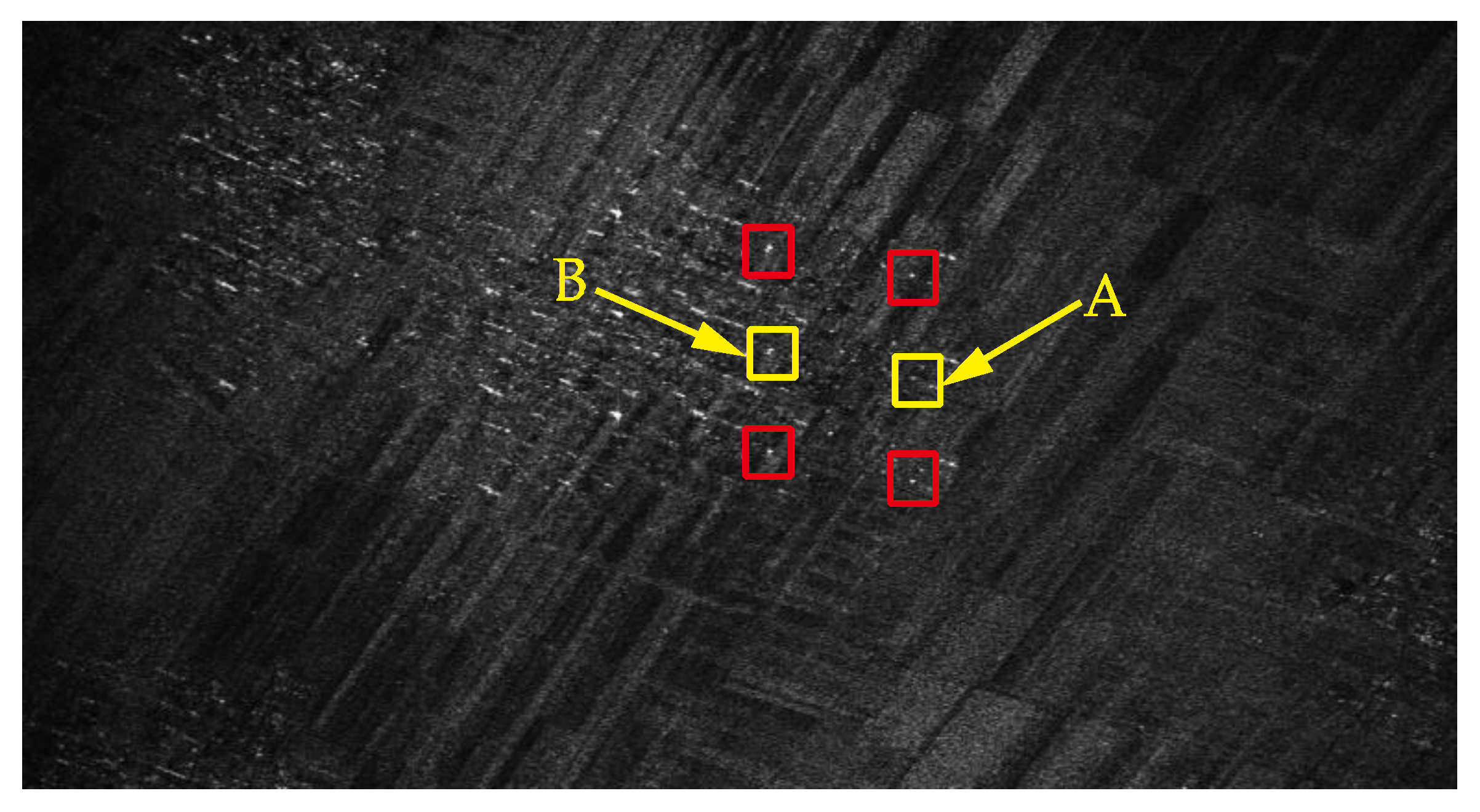
| Targets | Methods | AASR (dB) | |
|---|---|---|---|
| Left | Right | ||
| Target A | Single-channel | −10.4 | −6.1 |
| Traditional method | −15.9 | −11.7 | |
| Proposed method | Lower than Clutter | Lower than Clutter | |
| Target B | Single-channel | −6.8 | −9.2 |
| Traditional method | −12.5 | −15.7 | |
| Proposed method | Lower than Clutter | Lower than Clutter | |
Publisher’s Note: MDPI stays neutral with regard to jurisdictional claims in published maps and institutional affiliations. |
© 2022 by the authors. Licensee MDPI, Basel, Switzerland. This article is an open access article distributed under the terms and conditions of the Creative Commons Attribution (CC BY) license (https://creativecommons.org/licenses/by/4.0/).
Share and Cite
Zhang, C.; Li, H.; Li, L.; Liu, S.; Ding, Z. A Joint Estimation Method of the Channel Phase Error and Motion Error for Distributed SAR on a Single Airborne Platform Based on a Time-Domain Correlation Method. Remote Sens. 2022, 14, 3598. https://doi.org/10.3390/rs14153598
Zhang C, Li H, Li L, Liu S, Ding Z. A Joint Estimation Method of the Channel Phase Error and Motion Error for Distributed SAR on a Single Airborne Platform Based on a Time-Domain Correlation Method. Remote Sensing. 2022; 14(15):3598. https://doi.org/10.3390/rs14153598
Chicago/Turabian StyleZhang, Chi, Han Li, Linghao Li, Shujiang Liu, and Zegang Ding. 2022. "A Joint Estimation Method of the Channel Phase Error and Motion Error for Distributed SAR on a Single Airborne Platform Based on a Time-Domain Correlation Method" Remote Sensing 14, no. 15: 3598. https://doi.org/10.3390/rs14153598
APA StyleZhang, C., Li, H., Li, L., Liu, S., & Ding, Z. (2022). A Joint Estimation Method of the Channel Phase Error and Motion Error for Distributed SAR on a Single Airborne Platform Based on a Time-Domain Correlation Method. Remote Sensing, 14(15), 3598. https://doi.org/10.3390/rs14153598