Communication

Low Sidelobe Series-Fed Patch Planar Array with AMC Structure to Suppress Parasitic Radiation

1
School of Electronics and Information, Hangzhou Dianzi University, Hangzhou 310018, China
2
School of Information Science and Technology, Nantong University, Nantong 226019, China
*
Author to whom correspondence should be addressed.
Remote Sens. 2022, 14(15), 3597; https://doi.org/10.3390/rs14153597
Submission received: 21 June 2022 / Revised: 19 July 2022 / Accepted: 22 July 2022 / Published: 27 July 2022
(This article belongs to the Special Issue Radar Remote Sensing for Applications in Intelligent Transportation)

Abstract

:
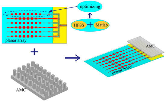
For automobile radar systems, the antenna array requires a low sidelobe level (SLL) to reduce interference. A low-SLL and low-cost planar antenna array are proposed in this article for millimeter-wave automotive radar applications. The proposed array consists of six linear series-fed patch arrays, a series distribution network using a grounded co-planar waveguide (GCPW), and a bed of nails. First, a hybrid HFSS-MATLAB optimization platform is set up to easily obtain good impedance matching and low SLL of the linear series-fed patch array. Then, a six-way GCPW power divider is designed to combine the optimized linear sub-array to achieve a planar array. However, since CCPW is a semi-open structure, like a microstrip line, the parasitic radiation generated by the GCPW feeding network will lead to the deterioration of the SLL. To solve this problem, a bed of nails—as an artificial magnetic conductor (AMC)—is designed and placed above the feeding networking to create an electromagnetic stopband in the working band. Its working mechanism has been explained in detail. The feeding network cannot effectively radiate electromagnetic waves into free space. Thus, the parasitic radiation can be suppressed. A low-SLL planar array prototype working at 79 GHz is designed, manufactured, and measured. The measured results confirm that the proposed low-SLL planar array has a −10 dB impedance bandwidth of 3 GHz from 77 to 80 GHz and a maximum peak gain of 21 dBi. The measured SLL is −24 dB and −23 dB in the E-plane and H-plane at 79 GHz, respectively. The proposed low SLL array can be used for adaptive cruise control (ACC) system applications.

Graphical Abstract

1. Introduction

The rise of driverless vehicles has raised higher demands and challenges for millimeter-wave (mmW) automotive radars [1,2,3,4,5,6]. At present, automotive radars have moved the working frequency to 76–81 GHz. According to the detection distance, an automotive radar can be classified into three main categories: long-range radar (LRR), medium-range radar (MRR), and short-range radar (SRR) [7]. The frequency band from 77 to 81 GHz is mainly used for MMR and SSR. Compared to 24 GH automotive radars, the 77/79 GHz automotive radars have a higher resolution and smaller volume. This will extend promising applications for intelligent transportation, such as adaptive cruise control (ACC), blind-spot detection (BSD), cross-traffic alerts (CTA), etc. Antennas, as a key component in automotive radar systems, have also been one of the subjects of research. To compensate for high path loss in the mmW band and to increase the detection range, the radar antennas usually need to be designed as high-gain antenna arrays. Furthermore, regardless of the application scenario, a low sidelobe level (SLL) is desirable to reduce the interference from clutter. Hence, for automotive radar systems, antenna arrays with low SLL, high gain, and low cost are the preferred choice.
Over the past decade, a lot of efforts have been devoted to designing antennas for automotive radars [8,9,10,11,12,13,14,15,16,17,18,19,20,21,22,23,24,25,26]. Some linear arrays are investigated in [8,9,10,11,12,13,14,15,16,17,18,19,20]. In consideration of the cost and compactness, the series-fed array is a good way to implement a linear array, such as a series-fed patch array [8,9,10,11], grid antenna array [12,13,14,15,16], comb-line array [17], etc. The SLL of the array is an important index in automotive radar systems, which reflects its anti-interference ability. The reported grid arrays and comb-line array have relatively high SLL due to the difficulty in suppressing sidelobe. Comparatively, the series-fed patch antenna array can more easily achieve a low SLL through a tapered patch width. In [8], a series-fed microstrip patch array of unequal interelement spacing and non-uniform amplitude is designed in the microwave band and achieves an SLL of −25 dB by using the differential evolution algorithm (DEA). Yet, the mutual coupling between elements is neglected for the simplicity of calculation, which is not desirable for a 79-GHz band with serious coupling. In [10], the series-fed linear and planar binomial patch arrays are designed by tapering the width of the radiation element. Both linear and planar binomial arrays provide an SLL of less than −28 dB. The reported low series-fed patch arrays [8,10,11] are designed in the microwave band. It is more difficult to design a low SLL series-fed patch array in the W-band due to the smaller wavelength. In [9], by adopting the design method of controlling the radiated-to-available power ratio (RAPA), three types of patch antennas are introduced to design a low SLL series-fed linear array. The SLLs below −17 dB are constructed over the operating band. A drawback of the reported methods for designing a low SLL is that they only consider the SLL, while they cannot optimize both S11 and SLL simultaneously.
To meet the detection of medium and long distances, high-gain planar arrays are required as transmitting antennas. Several different types of planar arrays have been designed for automotive radar applications [21,22,23,24,25,26]. Traditional microstrip-based feeding networks suffer from an increasing loss with the frequency increase in the mmW band. In particular, it will produce undesirable radiation (parasitic radiation), which has a bad effect on the radiation pattern and radar system. Given this concern, other transmission line technologies with closed structures, such as substrate-integrated wave and ridge waveguides, have been used to design a planar array. In [21], a planar array with a flat-shoulder shaped radiation pattern is achieved by adopting linear series-fed patch arrays and an SIW feeding network with a phase shift. The downside is that the SIW feeding network usually suffers from a large size due to the cut-off frequency. A high-gain slotted waveguide array with low SLL is proposed in [25] for vehicular applications in the 71–81 GHz band. A full-corporate single-ridge waveguide network with a Taylor amplitude distribution is used to design a low-SLL planar array. The SLLs below −19 dB and −24 dB are achieved in the E- and H-planes, respectively. Nevertheless, the full metal structure is very bulky and difficult to integrate with the front-end circuit. Several 77 GHz automotive radar systems are exhibited in [1,4,5]. It can be found that although the microstrip structure has some inherent shortcomings, the microstrip-based planar arrays are still the mainstream choice for automotive radar systems due to the compact structure, low cost, and ease of integration. Thus, it is very promising to design a simple and low-cost packaging to suppress the parasitic radiation from microstrip-based feeding networks. This will greatly improve the performance and reliability of automotive radar systems.
In this work, a compact and low-cost microstrip antenna planar array with low SLL is designed for LRR and MRR applications. The major contributions of this letter are shown as follows:
  • The reported methods for achieving the low SLL of a series-fed array cannot take into account the reflection coefficient. In this work, we built a Matlab-HFSS joint optimizing platform to easily optimize the SLL and S11 of the series-fed patch array.
  • Aimed at the problem of parasitic radiation from a microstrip-based feeding network, we propose an efficient method of loading an artificial magnetic conductor (AMC) to solve this problem. A bed-of-nails structure is used as an AMC and is arranged above the feeding network to suppress the unwanted radiation, which enables the radiation performance of the linear array to be unaffected. The proposed method has the advantage of a simple design and low cost. Meanwhile, there is no perfect electrical contact between the AMC structure and feeding network, which greatly facilitates assembly and enhances its practicality.
  • A prototype of the designed low-SLL microstrip antenna planar array is fabricated and measured for verification. The SLLs of −24 dB and −23 dB in the E- and H-planes at 79 GHz are realized, respectively. The measured results verify the correctness of the design.

2. Planar Array Design

2.1. The Design of a Low-SLL, Series-Fed Patch Antenna Sub-Array

Based on antenna array theory, the linear array can achieve a low SLL by tuning the amplitude and phase of each element. For a series-fed patch antenna array, the amplitude and phase are related to the patch width and element spacing, respectively. Therefore, its low SLL can be achieved by tapering the patch width and unequal element spacing. Figure 1 shows the geometry of the proposed low SLL series-fed microstrip patch antenna linear array. It will act as the sub-array of the proposed low-SLL planar array. The sub-array is designed on a single-layer Rogers RO3003 substrate ( ε r = 3, tan δ = 0.0013) with a thickness of h s = 0.127   mm , and it consists of 10 patch elements, an impedance transformer, and a feeding line with 50 ohms. The 10 patch elements with the same length l p are arranged symmetrically, and they are connected by a narrow microstrip line with width w t . The impedance transformer is utilized to achieve good impedance matching between the array and 50-Ω feeding line. As mentioned above, the sub-array is set to the unequal element spacing and tapered width to achieve low SLL. Since the patch elements of the series-fed sub-array have progressive phases, the element spacing between the adjacent patches needs to be kept at around one λg to maintain the radiation pattern in the broadside direction. (Here, λg is the guided wavelength in the substrate at 79 GHz). According to (1), the λg is 2.19 mm. The final sizes of the sub-array are given in Table 1:
λ g = c f ε r
where c and ε r are the speed of light and relative permittivity, respectively. For a series-fed patch antenna array, it is very laborious to achieve low SLL directly by parameter optimization or Taylor synthesis. To easily optimize SLL and S11, we construct a HFSS-MATLAB joint optimizing platform. Previously, a preliminary result has been reported in [27], but it does not have a detailed illustration and experimental results. Hence, the details of HFSS-Matlab joint optimization will be discussed here. The flowchart of the optimization method combining HFSS with Matlab is shown in Figure 2. First, a genetic algorithm (GA) is selected as the optimization algorithm because it has outstanding stochastic search capacity based on the mechanism of evolutionary biology. The GA starts with an initial set of random solutions, a population. Each individual in the population is coded as a chromosome, representing a solution of the target problem. Next, based on the MATLAB platform, HFSS-Matlab-API (HMA) is created as the interface between MATLAB and HFSS. The HMA provides a series of functions of HFSS operation commands. By using HMA, antenna models can be automatically created and simulated in HFSS. Thus, the precise results of each individual can be obtained. Then, the evaluation function is used to analyze and deal with these results provided by HFSS. Finally, according to the data from the evaluation function, good individuals will be selected by GA to enter the next iteration. The whole process will continue until the optimal result can be obtained.
Here, our goal is to achieve an SLL of −25 dB at 79 GHz and a working bandwidth covering 78 to 80 GHz. Accordingly, the objective function can be expressed as:
e 1 = { 25 | E S | | E S | < 25 0 | E S | 25 e 2 = { 30 | S 11 | > 10   dB   f o r m   78   t o   80   GHz 2 ω     t h e   o t h e r s C S = e 1 + e 2
where ES is the SLL at 79 GH in the E-plane. The ω represents the value of the bandwidth (|S11| ≤ −10 dB) in the specified frequency range of 78 to 80 GHz. The width of the patches ( w 1 w 5 ), the element spacing ( d 1 d 5 ), and the size of the impedance transformer ( w m , l m ) will be selected for optimization. Considering the actual patch size at 79 GHz, proper constraints may be added to the main function to make the whole optimizing process more efficient. For the main function, the patch width w i and spacing d i are set at a range of [0.3 mm, 1.5 mm] and [0.95 λ g , 1.05 λ g ], respectively. In this design, the configuration of GA is summarized as population = 20, crossover probability = 0.7, and mutation probability = 0.1.
By using hybrid HFSS-MATLAB optimization, a low-SLL, series-fed patch sub-array that satisfies our goals has been realized. The optimized dimensions are given in Table 1. The simulated reflection coefficient and gain are depicted in Figure 3a. The series-fed patch sub-array achieves good impedance matching in the range of 78 to 80 GHz and has stable gains at the working frequency band. Figure 3b–d show the simulated normalized radiation patterns at 78, 79, and 80 GHz. The series-fed patch sub-array exhibits good radiation characteristics in the operating band. It can be seen that the simulated SLL is −21 dB, −25 dB, and −24 dB at 78, 79, and 80 GHz in the E-plane, respectively.

2.2. The Design of the Feeding Network

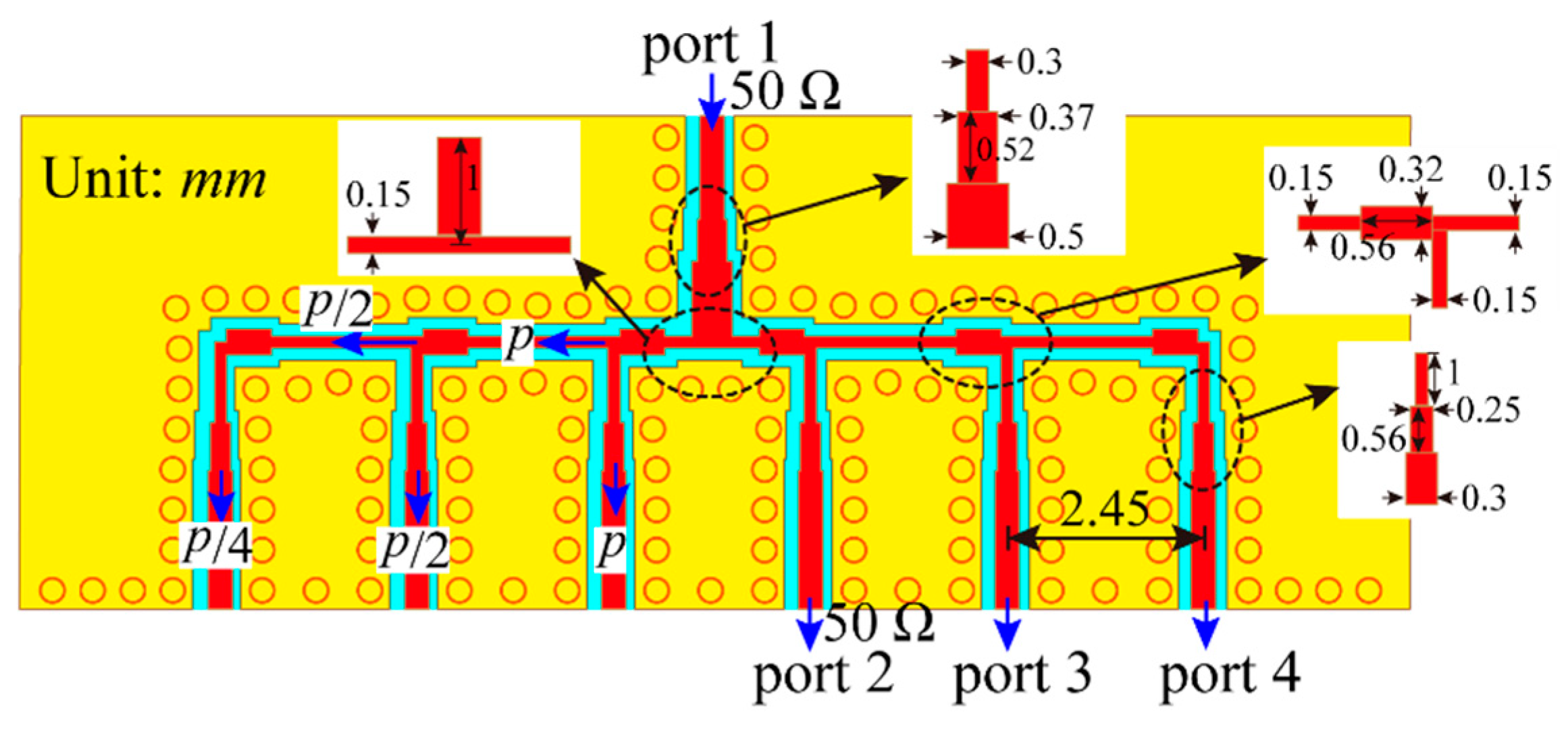
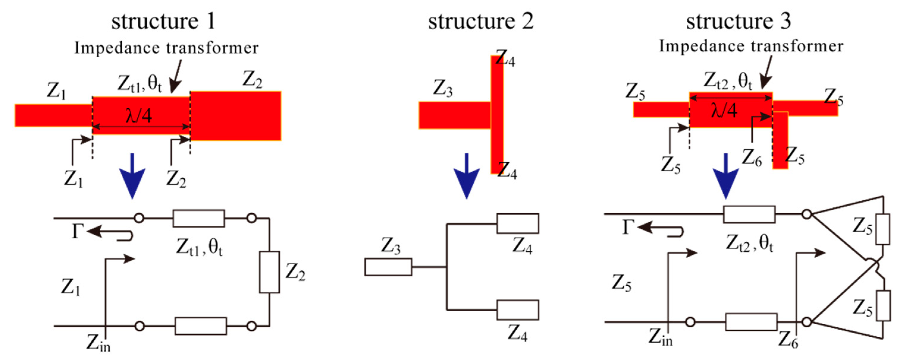
To implement a planar array, a full-corporate feeding network needs to be designed. We chose a series feeding way because it has a more compact structure compared to the parallel feeding way. Figure 4 shows the geometry of the designed series feeding network. The GCPW is used instead of the microstrip line, given the fact that its ground vias can effectively suppress surface waves. The designed feeding network consists of T-junction equal power dividers and an impedance transformer. As shown in Figure 5, three types of structures are used to design the series feeding network. To decrease the low SLL in the H-plane, unequal power distribution needs to be employed in the feeding network. Here, through a cascading equal power divider, the power ratio of 0.25:0.5:1:1:0.5:0.25 can be achieved, which is enough to ensure the SLL below −20 dB at 79 GHz. Similar to a series-fed sub-array, the series feeding network also has a progressive phase. Given this, the output ports should be spaced about one λg to remain in-phase. To achieve a good impedance matching of the feeding network, the key is to calculate the characteristic impedance (Zt1 and Zt2) of the impedance transformer. Structure 1 is based on a quarter wavelength impedance transformer for impedance matching. According to transmission line theory, the Zin can be derived as:
l = λ / 4 θ t = β l = π / 2 Z i n = Z t 1 Z 2 + j Z t 1 tan ( θ t ) Z t 1 + j Z 2 tan ( θ t ) = Z t 1 2 Z 2
where Z2, Zt1, and θt denote the characteristic impedance and electrical length of the transmission line, respectively. To achieve a perfect matching, i.e., the reflection coefficient Γ = 0, Zin = Z1 will be satisfied. Thus, the Zt1 can be obtained:
Z t 1 = Z 1 Z 2
Structure 2 is a typical T-junction equal power divider. It can be regarded as a parallel circuit. Thus, the relationship of the characteristic impedances can be expressed as:
1 Z 3 = 1 Z 4 + 1 Z 4
Structure 3 can be considered as the combination of structure 1 and structure 2. According to (3)–(5), the characteristic impedance Zt2 can be derived as:
Z 6 = Z 5 / 2 Z t 2 = Z 5 Z 6 = Z 5 2
In this design, according to (3)–(6), the initial design of the series feeding network can be completed by setting a characteristic impedance Z6 of structure 3. Then, the feeding network is further optimized in HFSS to obtain the desired results. Figure 4 gives the final design dimensions. Figure 6 presents the simulated results of the designed feeding network. It achieves a good impedance matching with |S11| < −15 dB covering 76 to 85 GHz. From Figure 6b, good agreement of the output phases can be observed from 77 to 81 GHz.

2.3. The Design and Analysis of AMC Structure

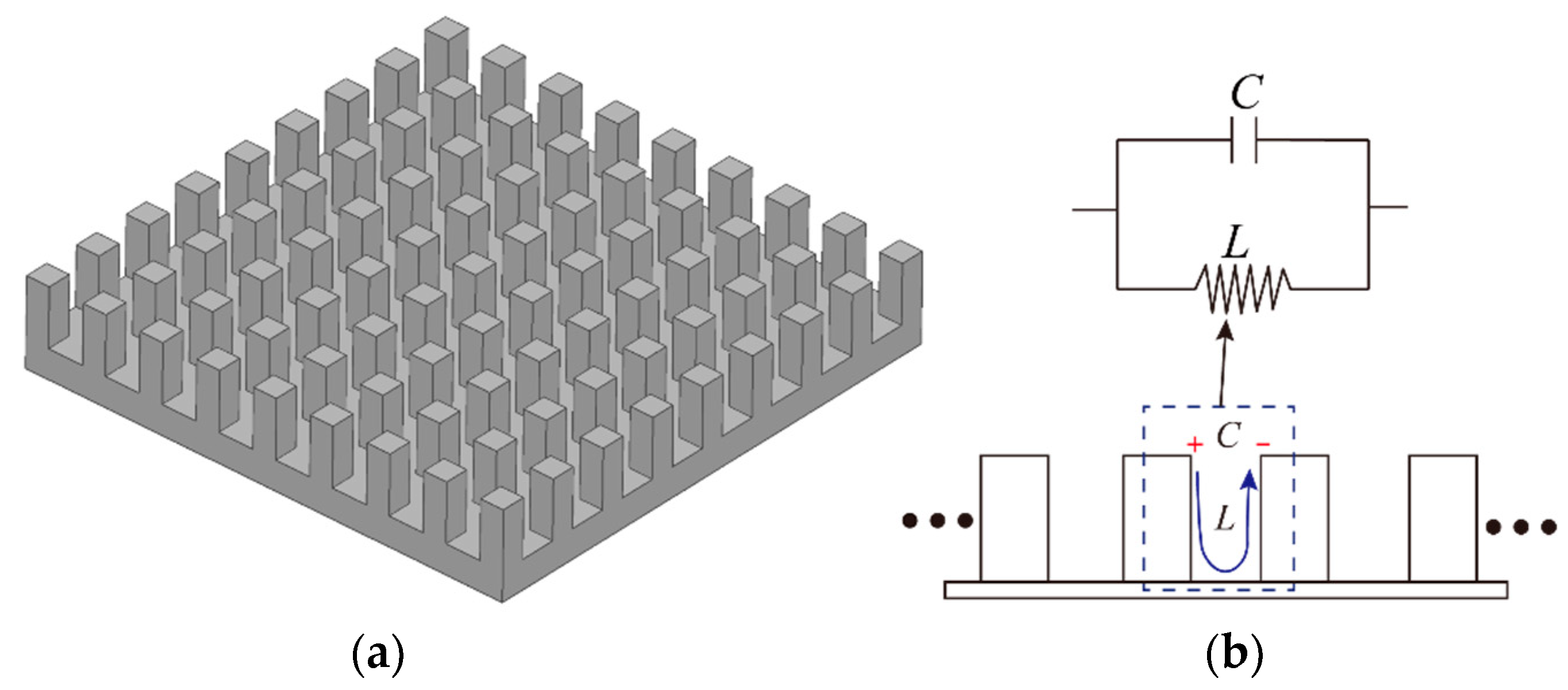
As mentioned in the introduction, the microstrip-based feeding network inevitably generates undesirable radiation due to its semi-open structure. In this sub-section, the principle and design process of using AMC to suppress the undesirable radiation will be elaborated upon. A new type of high-impedance electromagnetic (EM) surface is developed in [28]. The typical geometry is mushroom-like structures arranged in a two-dimensional lattice. In this design, we use a bed of nails formed by pins distributed in a two-dimensional lattice to achieve a high-impedance EM surface. Figure 7a shows the geometry of the bed of nails. Since the size and periodicity of the unit cell are much smaller than the operating wavelength, a simplified lumped circuit model can be used to describe the EM properties of the bed of nails. Figure 7b shows the equivalent lumped circuit model. It can be seen as a parallel resonant circuit, consisting of capacitance and inductance. The surface impedance can be expressed as:
Z = j ω L 1 ω 2 L C
The impedance is infinite near the resonant frequency ω 0 . In the frequency range where the surface impedance is very high, the tangential magnetic field is small and the image currents are in-phase [28]. Based on these properties, the high-impedance surface can be regarded as a kind of AMC:
ω 0 = 1 L C
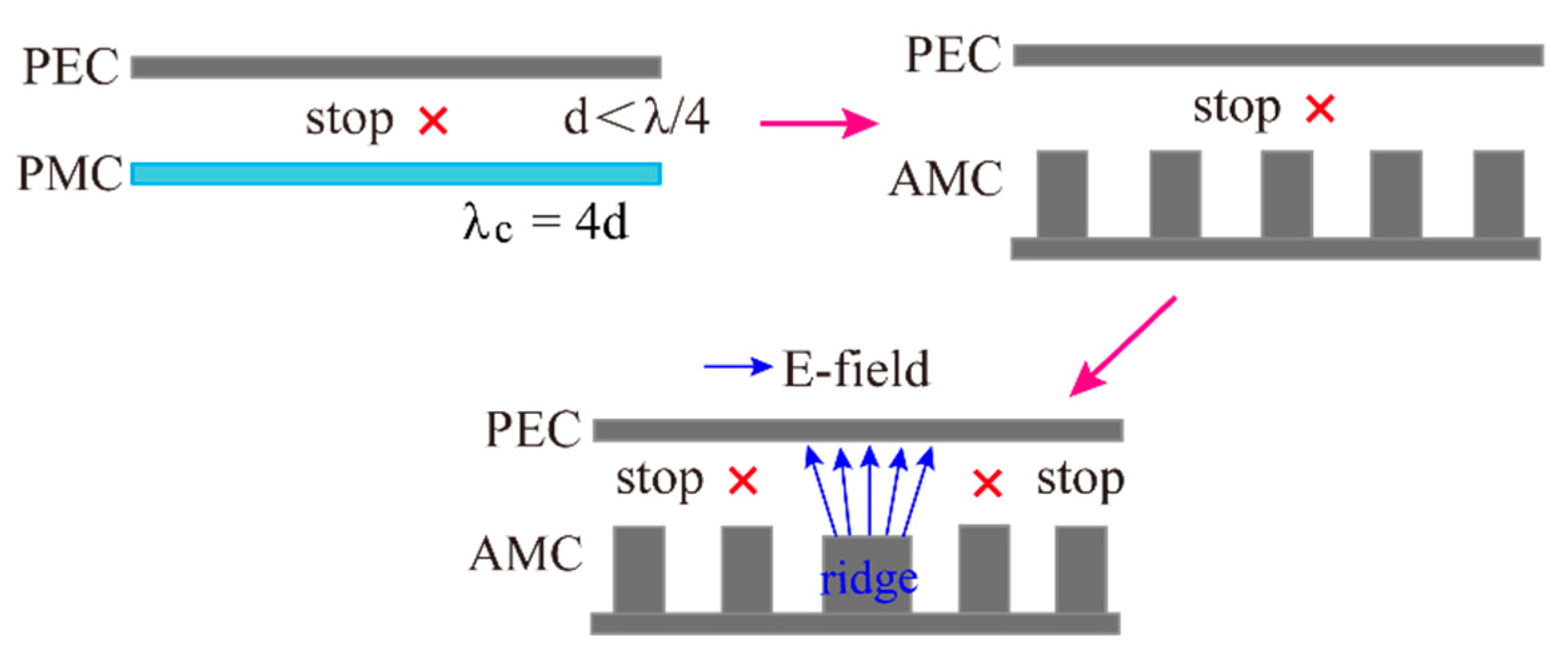
Based on the theory of soft and hard surfaces [29], and some related research [30,31,32], a new metamaterial-based ridge gap waveguide technology is proposed in [33]. Figure 8 plotted the evolution process of the ridge gap waveguide. A TEM wave cannot propagate between a perfect electric conductor (PEC) and perfect magnetic conductor (PMC) due to the limitation of boundary conditions. When the distance between the PEC and PMC is smaller than a quarter wavelength, no waves can propagate in the gap (i.e., all modes are below cut-off [34]). This is similar to the cut-off characteristic of a rectangular waveguide. Thus, a frequency stopband can be created. As we all know, the PMC does not exist in nature. The bed of nails with a high surface impedance (regarded as AMC) is used to constitute an approximate PMC surface. If a metal ridge or metal strip is embedded in the PMC, the EM wave is bound to follow the ridge, and the electric fields are located between the top of the ridge and PEC, like a microstrip line located over a metal ground. As a result, in a frequency stopband, a local quasi-TEM mode electromagnetic wave can propagate between the ridge and PEC, while wave propagation at the sides of the ridge is prohibited.
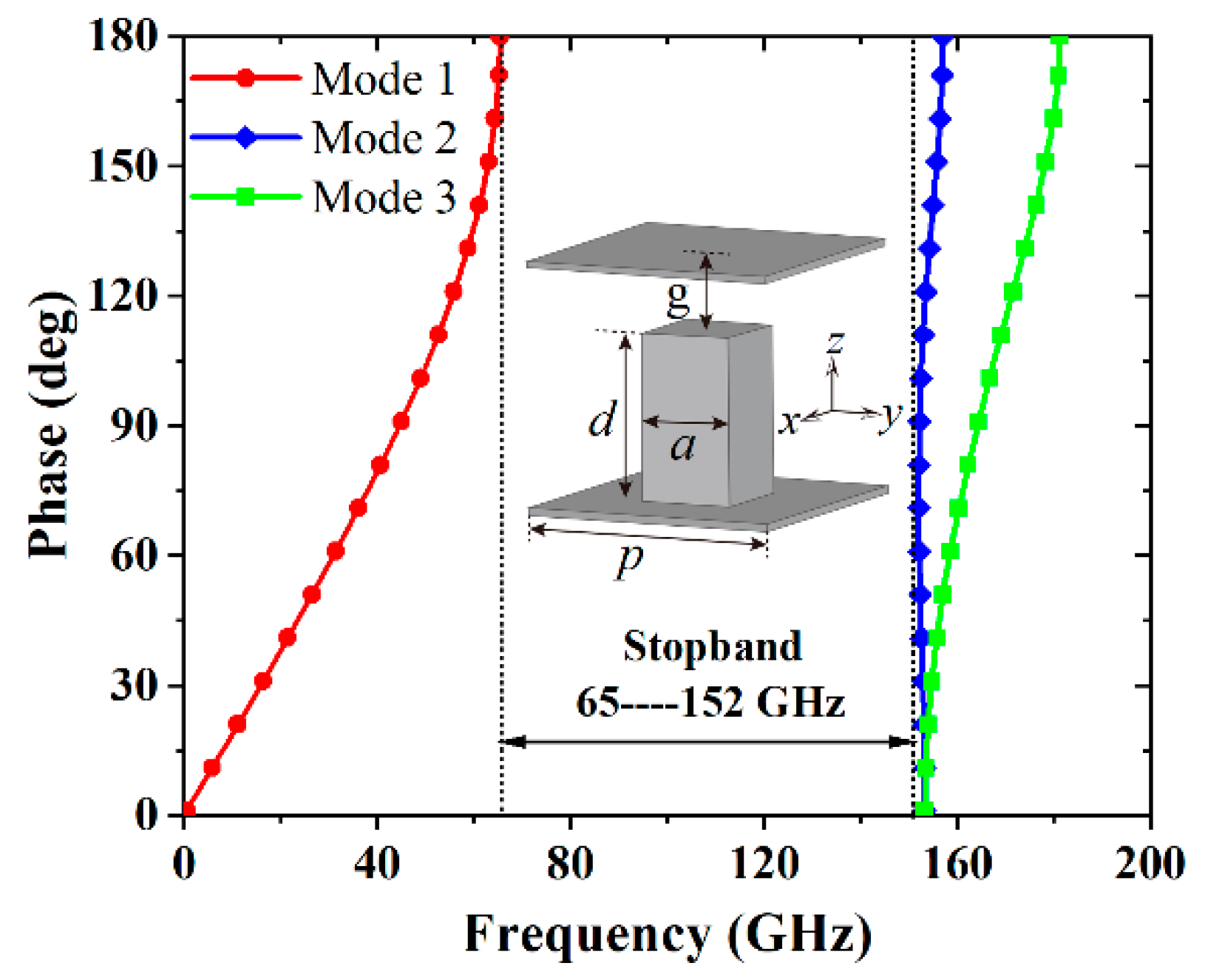
Inspired by the concept of a gap waveguide (GW), we utilize the stopband features on both sides of the metal ridge to shield the parasitic radiation from a microstrip-based feeding network. To do this, a unit cell of GW needs to be designed. The EM stopband can be observed by the dispersion curves of the modes. Figure 9 shows the dispersion diagram of the unit cell. The dispersion curve is calculated by the Eigenmode solver of the CST studio. A stopband from 65 to 152 GHz is obtained by tuning the dimensions of the pin and the gap. To further understand the characteristics of the unit cell, the effect of several parameters on the stopband was studied. The influence of the pin height on the stopband is given in Figure 10a. As the high d increases, the stopband moves towards the lower frequency band. The effect of gap g is then studied. As shown in Figure 10b, the working frequency band of mode 1 moves towards a higher frequency with the increase of g , while mode 2 exhibits the opposite variation. Accordingly, the stopband bandwidth is significantly reduced as g increases. Figure 10c shows the effect of different intervals between pins on the stopband. The interval p has a significant effect on mode 2. As p increases, the stopband moves slightly towards the lower band and the stopband bandwidth decreases. Figure 10d shows the influence of the pin width a on the stopband. It can be found that the stopband is only slightly affected.

2.4. The Design and Analysis of the Proposed Low-SLL Planar Array

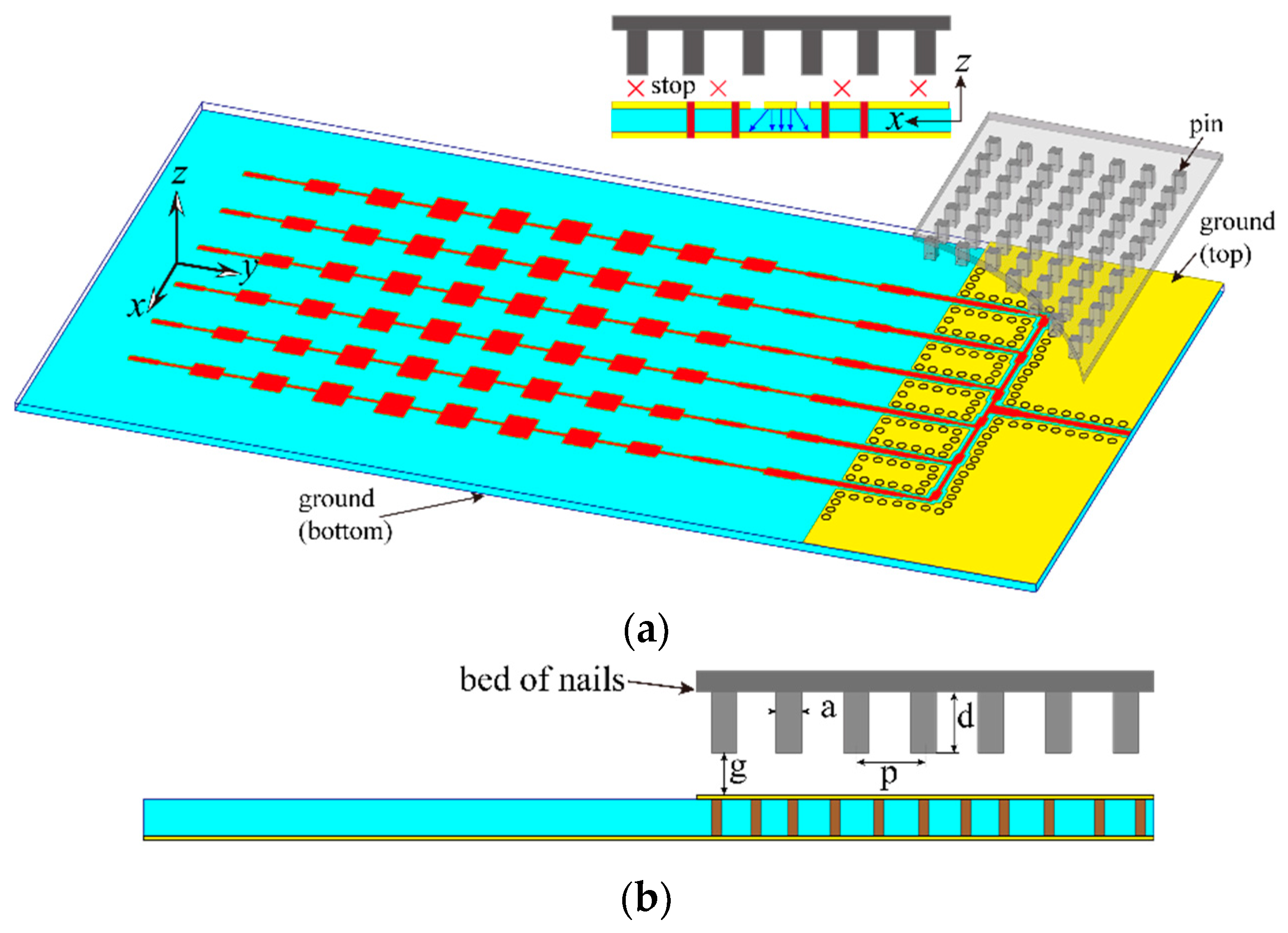
Figure 11 shows the overall configuration of the proposed low-SLL planar array. The planar array consists of the optimized series-fed sub-array and a 1-to-6 series feeding network. Due to the semi-open structure of GCPW, the parasitic radiation from the feeding networking will deteriorate the SLL of the radiation pattern. It is necessary to suppress parasitic radiation to keep a good radiation performance of the planar array. A bed of nails as an AMC is designed and placed above the feeding networking. As illustrated by the above theory, a stopband will be created in the gap between the bed of nails and the top ground of the feeding network, while the quasi-TEM wave can still propagate between the signal line of GCPW and the ground on bottom. This is similar to an inverted microstrip gap waveguide (IMGP) structure [35]. Meanwhile, the parallel plate modes do not appear due to the EM stopband, which enables the array to maintain its original performance. The feeding network will not be able to radiate EM waves into outer space. Therefore, the parasitic radiation of the feeding network can be suppressed in the operating frequency band.
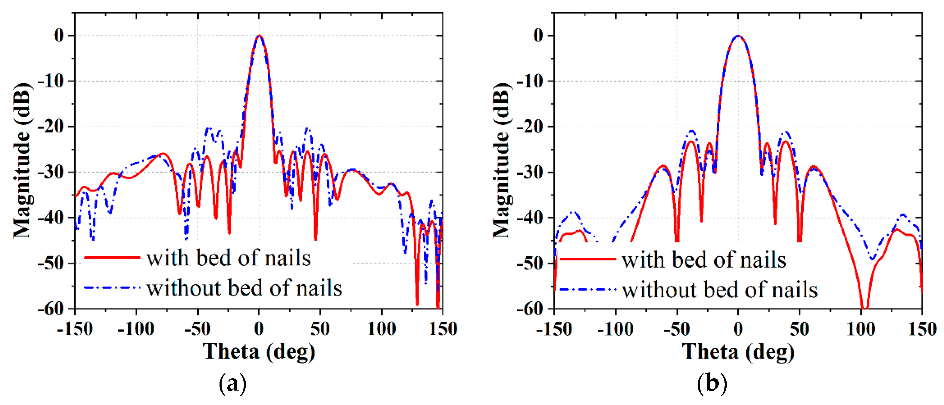
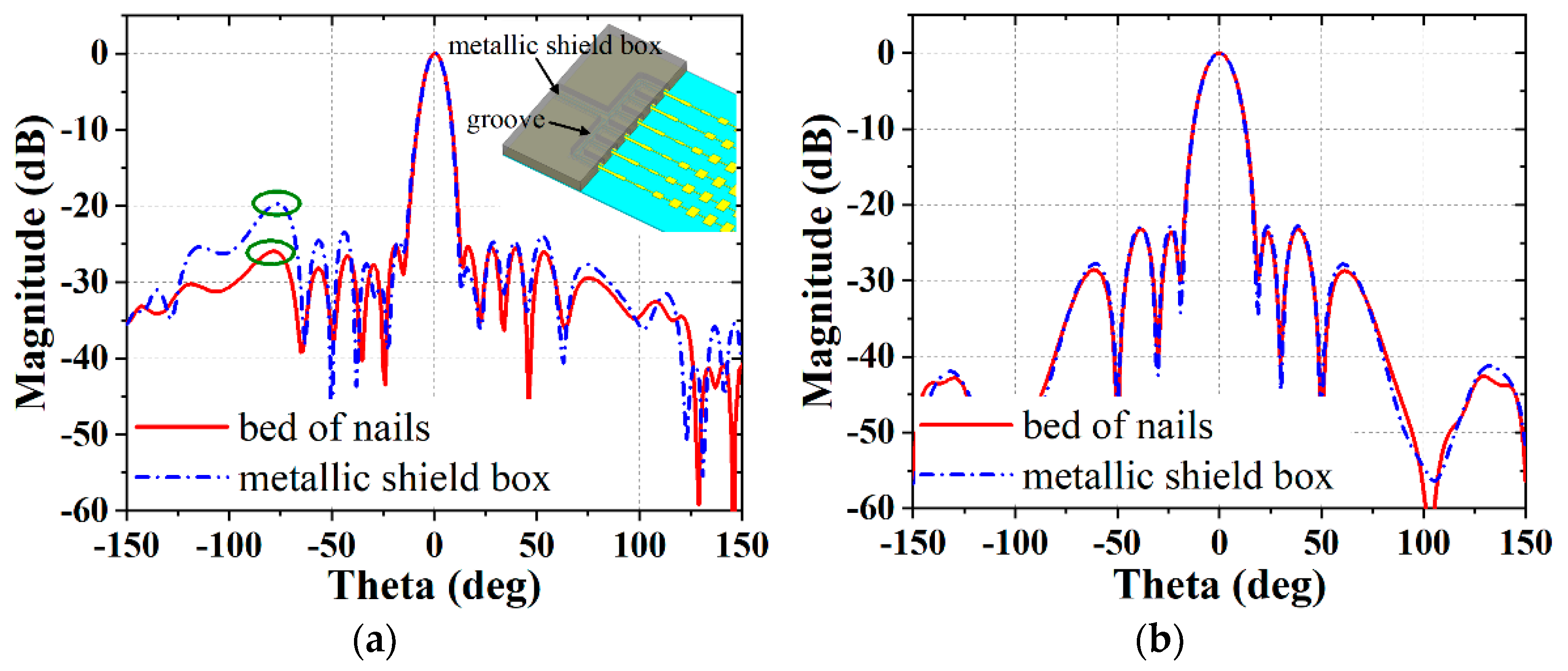
To further understand this design, the magnitude of the electric field with and without the bed of nails in the plane above the feeding network was plotted in Figure 12. When there is no bed of nails, the electric field above the feeding network is more cluttered and has many speckles with strong energy. Although the radiated energy is much weaker than the main beam of the array, it is comparable to the energy of the sidelobes. It is foreseeable that they will interfere with the radiation performance of the array, especially the sidelobes. It can be seen from Figure 12b that when the bed of nails is loaded, the strong electric field only appears above the signal line, while the amplitude of the electric field in other regions is almost zero due to the existence of the electromagnetic stopband. Thus, the feeding network will not produce any EM leakage. In addition, any parallel plate modes that interfere with the array performance do not exist in the gap. Figure 13 shows the simulated radiation patterns of the proposed low-SLL array with and without the bed of nails at 79 GHz. The array without a bed of nails has an SLL of −20 and −21 dB in the E-plane and H-plane, respectively. By loading a bed of nails as an AMC, the SLLs of the array are reduced by 5 dB and 2 dB in the E-plane and H-plane, respectively. This verifies the correctness of the design. Figure 14 shows the comparison of the radiation pattern between the proposed SLL array and the array with the common package of a metal box. It can be found that the radiation pattern of the array with the metal-shielded box has a relatively high SLL (−20 dB) at a negative E-plane angle due to the influence of the high-order cavity resonance mode and metallic sidewall.

3. Results and Discussion

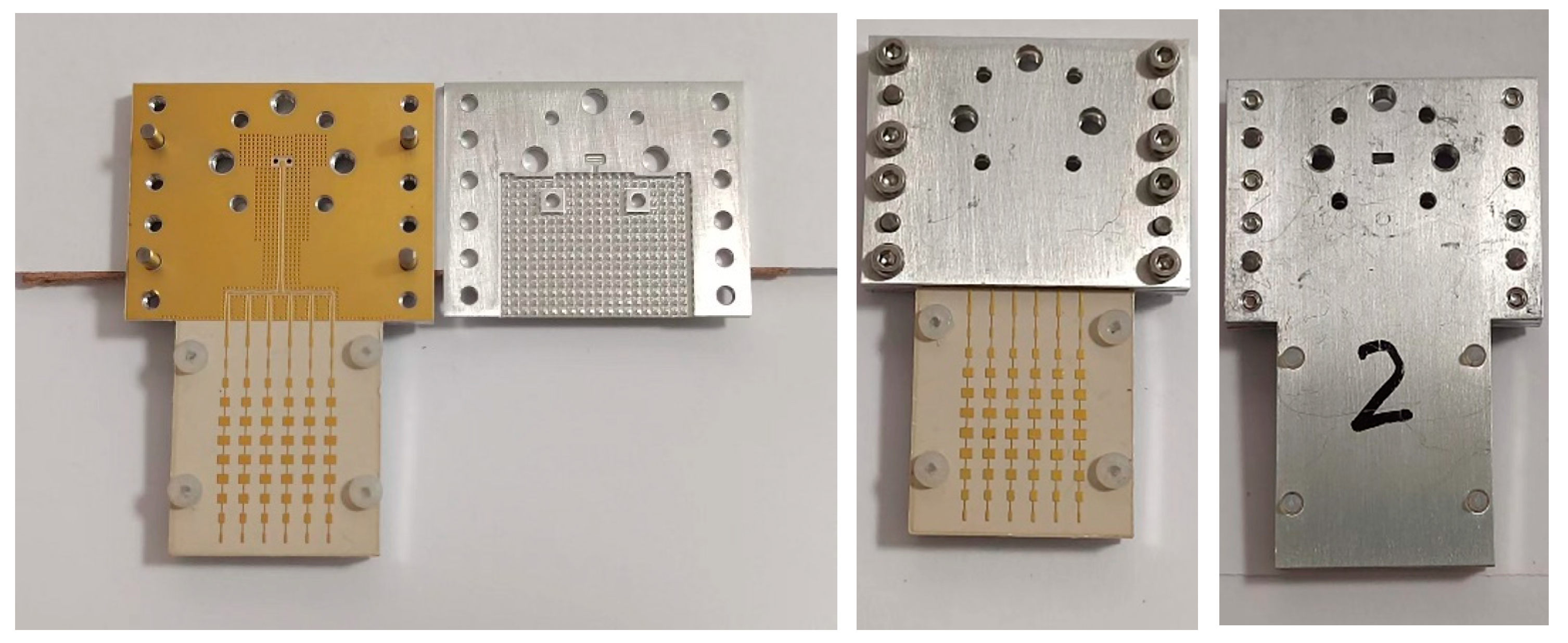
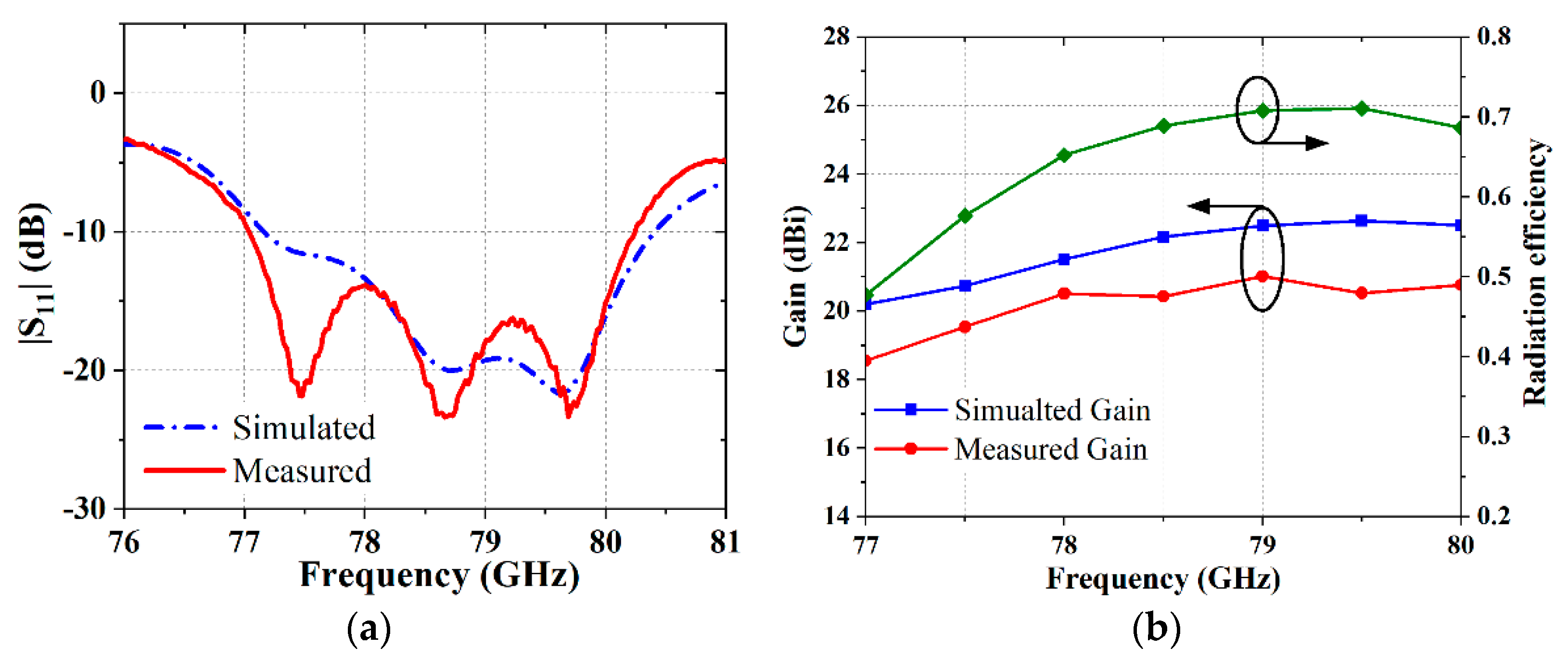
To measure the designed planar array, a microstrip line to WR-10 waveguide transition is designed and achieves good performance in the frequency band of interest. Then, a prototype of the proposed SLL patch array was fabricated. Figure 15 shows the photograph of a fabricated array prototype. Agilent Vector Network analyzer N5245A and WR-10 mm-wave extenders are employed to measure the reflection coefficient. The measured and simulated reflection coefficients are plotted in Figure 16a. The measured result shows that the frequency range of | S 11 | < 10   dB is 77 to 80.2 GHz. There is a slight discrepancy between the measured and simulated reflection coefficients. The reason can be attributed to manufacturing and assembly tolerances of the transition structure. Given the existence of a quarter-wavelength back-short, small manufacturing errors in the transition will result in a discernible difference in terms of the reflection coefficient.
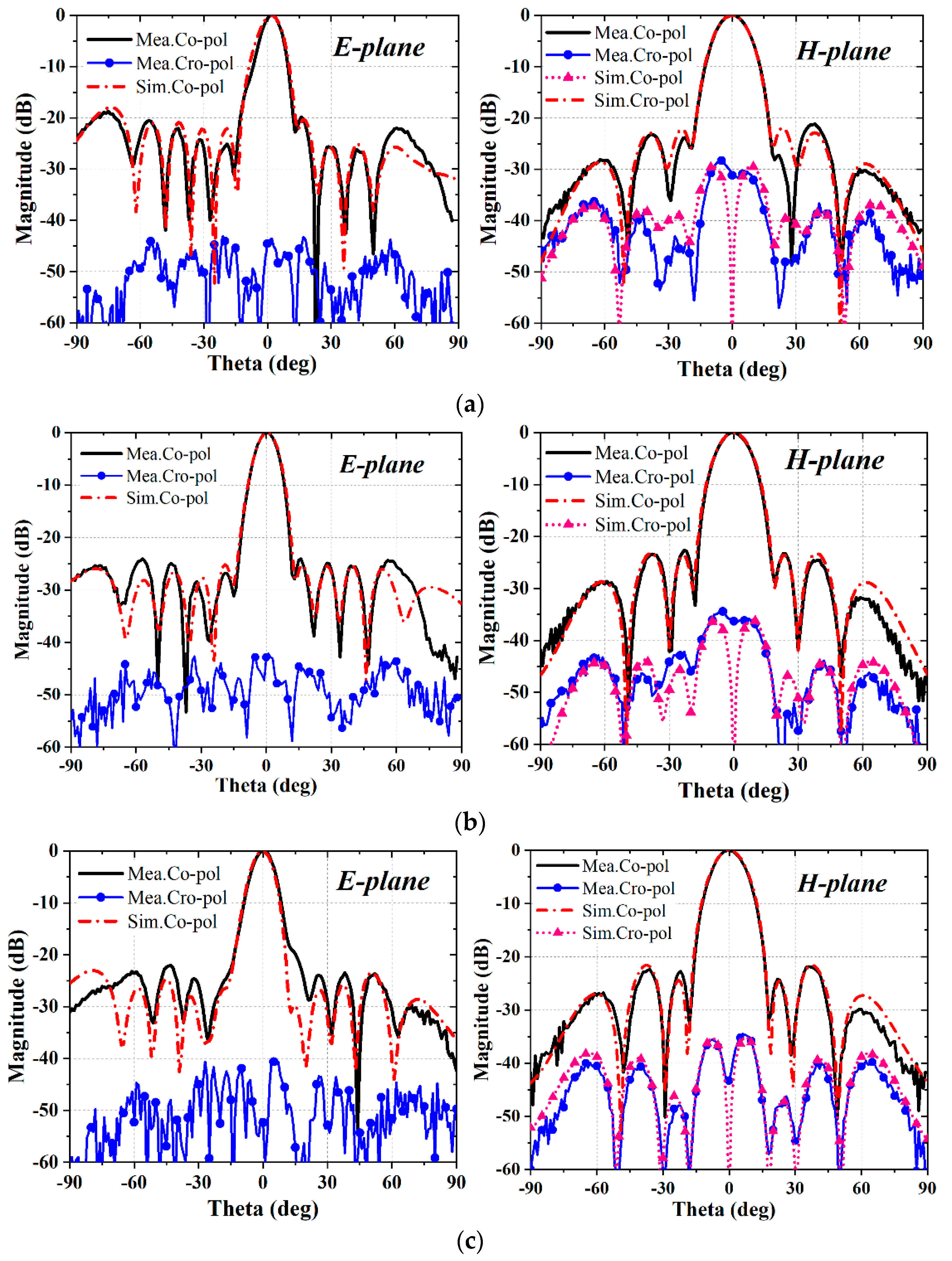
Moreover, the gains and radiation patterns are measured in an anechoic chamber with a far-field test system. Figure 16b shows the measured and simulated gain in the operating band. The measured peak gains are 20.5 dBi at 78 GHz, 21 dBi at 79 GHz, and 20.76 dBi at 80 GHz, respectively. The measured gains are, on average, 1.5 dB lower than the simulated ones. One reason for this comes from the uncertain dielectric loss tangent. This is because the nominal loss tangent of RO3003 is 0.0013 at 10 GHz, but the design experience shows that the loss tangent of the substrate increases with the operating frequency. Therefore, the actual dielectric loss is higher than the nominal value. Another reason may come from the insertion loss of the microstrip line to the waveguide transition. Usually, the experimental insertion loss of the transition is higher than the simulated insertion loss due to the material loss (including dielectric loss, conductor loss, and connection loss). Since the directivity cannot be measured in our far-field chamber, only the simulated radiation efficiency is given in Figure 16b. It can be seen that the radiation efficiency is higher than 70% at 79 GHz. Figure 17 shows the simulated and measured radiation in the E-plane and H-plane at 78 GHz, 79 GHz, and 80 GHz, which indicates a good agreement between these two results. The measured SLLs of the E-plane are −20 dB, −24 dB, and −22 dB at 78, 79, and 80 GHz, respectively. The measured SLLs of the H-plane are −21 dB, −23 dB, −22 dB at 78, 79, and 80 GHz, respectively. All of these values are slightly higher than the simulated ones, which are mainly caused by the multipath reflection from the metallic bracket in the anechoic chamber.

4. Conclusions

A low-SLL planar array based on linear series-fed patch sub-arrays has been presented in this work. The technical contributions of this work are twofold. On the one hand, a hybrid HFSS-Matlab optimization method is constructed to easily optimize a series-fed sub-array in terms of impedance matching and SLL. The complete design framework of the HFSS-Matlab joint optimizing platform is given. Owing to the accurate results provided by HFSS, the series-fed patch sub-array achieves an SLL of −25 dB in the E-plane at 79 GHz and obtains a good impedance matching from 78 to 80 GHz. Combining a 1-to-6 GCPW distribution network and the optimized series-fed patch array, a high-gain planar array is designed. On the other hand, we propose a simple and effective method for loading the AMC to suppress unwanted radiation from the microstrip-based feeding network. A bed of nails is designed and acts as an AMC. It has the advantages of being low cost and easily fabricated. There is no perfect electrical contact between the AMC structure and feeding network, which greatly facilitates assembly and enhances its practicality. Meanwhile, owing to the EM stopband between the bed of nails and metal ground, the parallel plate modes that might exist in the package of a common metal box do not appear. For verification, the proposed low-SLL planar array is designed, fabricated, and measured. The measured results show that the array has good impedance matching in the designed band from 78 to 80 GHz and a stable radiation performance. Meanwhile, the measured SLLs at 79 GHz are −24 dB and −23 dB in the E-plane and H-plane, which is in good agreement with the simulated results. With the metrics of low cost, low SLL, stable radiation, and ease of integration, the proposed low-SLL planar array is promising for 79-GHz automobile radar applications.

Author Contributions

Conceptualization, Q.T. and K.F.; data curation, Q.T.; formal analysis, Q.T.; methodology, Q.T.; software, Q.T.; validation, K.F., W.Y. and G.L.; investigation, Q.T.; resources, K.F. and G.L.; writing—original draft preparation, Q.T.; writing—review and editing, K.F., W.Y. and G.L.; visualization, Q.T.; supervision, K.F. and G.L.; project administration, K.F.; funding acquisition, K.F. and G.L. All authors have read and agreed to the published version of the manuscript.

Funding

This research was funded by the National Natural Science Foundation of China under Grant 61801156, and Grant 62125105.

Data Availability Statement

Not applicable.

Acknowledgments

The authors would like to thank W. Sun for their assistance in the measurement.

Conflicts of Interest

The authors declare that they have no conflict of interest in the publication of this manuscript.

References

  1. Ku, B.H.; Schmalenberg, P.; Inac, O.; Gurbuz, O.D.; Lee, J.S.; Shiozaki, K.J.; Rebeiz, G.M. A 77–81-GHz 16-Element Phased-Array Receiver With ±50° Beam Scanning for Advance Automotive Radars. IEEE Trans. Microw. Theory Tech. 2014, 62, 2823–2832. [Google Scholar] [CrossRef]
  2. Ahmad, W.A.; Kucharski, M.; Ergintav, A.; Ng, H.J.; Kissinger, D.A. Planar Differential Wide Fan-Beam Antenna Array Architecture: Modular high-gain array for 79-GHz multiple-input, multiple-output radar applications. IEEE Antennas Propag. Mag. 2021, 63, 21–23. [Google Scholar] [CrossRef]
  3. Engels, F.; Heidenreich, P.; Zoubir, A.M.; Jondral, F.K.; Wintermantel, M. Advances in Automotive Radar: A framework on computationally efficient high-resolution frequency estimation. IEEE Signal Process. Mag. 2017, 34, 36–46. [Google Scholar] [CrossRef]
  4. Menzel, M.; Moebius, A. Antenna Concepts for Millimeter-Wave Automotive Radar Sensors. Proc. IEEE 2012, 100, 2372–2379. [Google Scholar] [CrossRef]
  5. Hasch, J.; Topak, E.; Schnabel, R.; Zwick, T.; Weigel, R.; Waldschmidt, C. Millimeter-Wave Technology for Automotive Radar Sensors in the 77 GHz Frequency Band. IEEE Trans. Microw. Theory Tech. 2012, 60, 845–860. [Google Scholar] [CrossRef]
  6. Harter, M.; Hildebrandt, J.; Ziroff, A.; Zwick, T. Self-Calibration of a 3-D-Digital Beamforming Radar System for Automotive Applications with Installation Behind Automotive Covers. IEEE Trans. Microw. Theory Tech. 2016, 64, 2994–3000. [Google Scholar] [CrossRef]
  7. Pimentel, J.R. Data heterogeneity, characterization, and integration in the context of autonomous vehicles. In Proceedings of the IECON 2017—43rd Annual Conference of the IEEE Industrial Electronics Society, Beijing, China, 29 October–1 November 2017; pp. 4571–4576. [Google Scholar]
  8. Yin, J.; Wu, Q.; Yu, C.; Wang, H.; Hong, W. Low-Sidelobe-Level Series-Fed Microstrip Antenna Array of Unequal Interelement Spacing. IEEE Antennas Wirel. Propag. Lett. 2017, 16, 1695–1698. [Google Scholar] [CrossRef]
  9. Kang, Y.; Noh, E.; Kim, K. Design of Traveling-Wave Series-Fed Microstrip Array with a Low Sidelobe Level. IEEE Antennas Wirel. Propag. Lett. 2020, 19, 1395–1399. [Google Scholar] [CrossRef]
  10. Chopra, R.; Kumar, G. Series-Fed Binomial Microstrip Arrays for Extremely Low Sidelobe Level. IEEE Trans. Antennas Propag. 2019, 67, 4275–4279. [Google Scholar] [CrossRef]
  11. Khalili, H.; Mohammadpour-Aghdam, K.; Alamdar, S.; Mohammad-Taheri, M. Low-Cost Series-Fed Microstrip Antenna Arrays with Extremely Low Sidelobe Levels. IEEE Trans. Antennas Propag. 2018, 66, 4606–4612. [Google Scholar] [CrossRef]
  12. Arnieri, A.; Greco, F.; Boccia, L.; Amendola, G. A Reduced Size Planar Grid Array Antenna for Automotive Radar Sensors. IEEE Antennas Wirel. Propag. Lett. 2018, 17, 2389–2393. [Google Scholar] [CrossRef]
  13. Alsath, M.G.N.; Lawrance, L.; Kanagasabai, M. Bandwidth-Enhanced Grid Array Antenna for UWB Automotive Radar Sensors. IEEE Trans. Antennas Propag. 2015, 63, 5215–5219. [Google Scholar] [CrossRef]
  14. Khan, O.; Meyer, J.; Baur, K.; Waldschmidt, C. Hybrid Thin Film Antenna for Automotive Radar at 79 GHz. IEEE Trans. Antennas Propag. 2017, 65, 5076–5085. [Google Scholar] [CrossRef]
  15. Zhang, L.; Zhang, W.; Zhang, Y.P. Microstrip Grid and Comb Array Antennas. IEEE Trans. Antennas Propag. 2011, 59, 4077–4084. [Google Scholar] [CrossRef]
  16. Mosalanejad, M.; Ocket, I.; Soens, C.; Vandenbosch, G.A.E. Multilayer Compact Grid Antenna Array for 79 GHz Automotive Radar Applications. IEEE Antennas Wirel. Propag. Lett. 2018, 17, 1677–1681. [Google Scholar] [CrossRef]
  17. Mosalanejad, M.; Ocket, I.; Soens, C.; Vandenbosch, G.A.E. Wideband Compact Comb-Line Antenna Array for 79 GHz Automotive Radar Applications. IEEE Antennas Wirel. Propag. Lett. 2018, 17, 1580–1583. [Google Scholar] [CrossRef]
  18. Yoo, S.; Milyakh, Y.; Kim, H.; Hong, C.; Choo, H. Patch Array Antenna Using a Dual Coupled Feeding Structure for 79 GHz Automotive Radar Applications. IEEE Antennas Wirel. Propag. Lett. 2020, 19, 676–679. [Google Scholar] [CrossRef]
  19. Yu, C.A.; Jin, H.Y.; Cao, Y.; Su, G.R.; Che, W.Q.; Chin, K.S. 24 GHz Horizontally Polarized Automotive Antenna Arrays With Wide Fan Beam and High Gain. IEEE Trans. Antennas Propag. 2019, 67, 892–904. [Google Scholar] [CrossRef]
  20. Yang, X.Y.; Liu, X.F. Design of a Wide-Beam Microstrip Array Antenna for Automotive Radar Application. IEEE Access 2021, 9, 142340–142347. [Google Scholar] [CrossRef]
  21. Xu, J.; Hong, W.; Zhang, H.; Wang, G.L.; Yu, Y.R.; Jiang, Z.H. An Array Antenna for Both Long- and Medium-Range 77 GHz Automotive Radar Applications. IEEE Trans. Antennas Propag. 2017, 65, 7207–7216. [Google Scholar] [CrossRef]
  22. Xu, J.F.; Chen, Z.N.; Qing, X.M. CPW Center-Fed Single-Layer SIW Slot Antenna Array for Automotive Radars. IEEE Trans. Antennas Propag. 2014, 62, 4528–4536. [Google Scholar] [CrossRef]
  23. Shin, D.H.; Kim, K.B.; Kim, J.G.; Park, S.O. Design of Null-Filling Antenna for Automotive Radar Using the Genetic Algorithm. IEEE Antennas Wirel. Propag. Lett. 2014, 13, 738–741. [Google Scholar] [CrossRef]
  24. Chen, R.S.; Zhu, L.; Wong, S.W.; Yu, X.Z.; Li, Y.; Zhang, L.; He, Y.J. Low-Sidelobe Cavity-Backed Slot Antenna Array With Simplified Feeding Structure for Vehicular Communications. IEEE Trans. Veh. Technol. 2021, 70, 3652–3660. [Google Scholar] [CrossRef]
  25. Qin, L.T.; Lu, Y.L.; You, Q.C.; Wang, Y.; Huang, J.F.; Gardner, P. Millimeter-Wave Slotted Waveguide Array With Unequal Beamwidths and Low Sidelobe Levels for Vehicle Radars and Communications. IEEE Trans. Veh. Technol. 2018, 70, 10574–10582. [Google Scholar] [CrossRef]
  26. Yu, Y.R.; Hong, W.; Zhang, H.; Xu, J.; Jiang, Z.H. Optimization and Implementation of SIW Slot Array for Both Medium- and Long-Range 77 GHz Automotive Radar Application. IEEE Trans. Antennas Propag. 2018, 66, 3769–3774. [Google Scholar] [CrossRef]
  27. Tan, Q.Q.; Chen, K.; Fan, K.K.; Luo, G.Q. A Low-sidelobe Series-fed Microstrip Patch Antenna Array for 77 GHz Automotive Radar Applications. In Proceedings of the 2020 Cross Strait Radio Science & Wireless Technology Conference (CSRSWTC), Fuzhou, China, 3–16 December 2020; pp. 1–3. [Google Scholar]
  28. Sievenpiper, D.; Zhang, L.J.; Broas, R.F.J.; Alexopolous, N.G.; Yablonovitch, E. High-impedance electromagnetic surfaces with a forbidden frequency band. IEEE Trans. Microw. Theory Tech. 1999, 47, 2059–2074. [Google Scholar] [CrossRef] [Green Version]
  29. Kildal, P.S. Artificially soft and hard surfaces in electromagnetics. IEEE Trans. Antennas Propag. 1990, 38, 1537–1544. [Google Scholar] [CrossRef]
  30. Valero-Nogueira, A.; Alfonso, E.; Herranz, J.I.; Baquero, M. Planar slot-array antenna fed by an oversized quasi-TEM waveguide. Microw. Opt. Technol. Lett. 2007, 49, 1875–1877. [Google Scholar] [CrossRef]
  31. Alfonso, E.; Kildal, P.S.; Valero, A.; Herranz, J.H. Study of local quasi-TEM wave in oversize waveguide with one hard wall for killing higher order global modes. In Proceedings of the 2008 IEEE Antennas and Propagation Society International Symposium, San Diego, CA, USA, 5–11 July 2008; pp. 1–4. [Google Scholar]
  32. Padilla de la Torre, P.; Fernández, J.M.; Sierra-Castañer, M. Characterization of artificial magnetic conductor strips for parallel plate planar antennas. Microw. Opt. Technol. Lett. 2008, 50, 498–504. [Google Scholar] [CrossRef] [Green Version]
  33. Kildal, P.S.; Alfonso, E.; Valero-Nogueira, A.; Raji-Iglesias, E. Local metamaterial-based waveguides in gaps between parallel metal plates. IEEE Antennas Wirel. Propag. Lett. 2009, 8, 84–87. [Google Scholar] [CrossRef]
  34. Alfonso, E.; Kildal, P.S.P.; Valero-Nogueira, A.; Herranz, J.I. Numerical analysis of a metamaterial-based ridge gap waveguide with a bed of nails as parallel-plate mode killer. In Proceedings of the 2009 3rd European Conference on Antennas and Propagation, Berlin, Germany, 23–27 March 2009; pp. 23–27. [Google Scholar]
  35. Liu, J.L.; Yang, J.; Zaman, A.U. Analytical Solutions to Characteristic Impedance and Losses of Inverted Microstrip Gap Waveguide Based on Variational Method. IEEE Trans. Antennas Propag. 2018, 66, 7049–7057. [Google Scholar] [CrossRef] [Green Version]
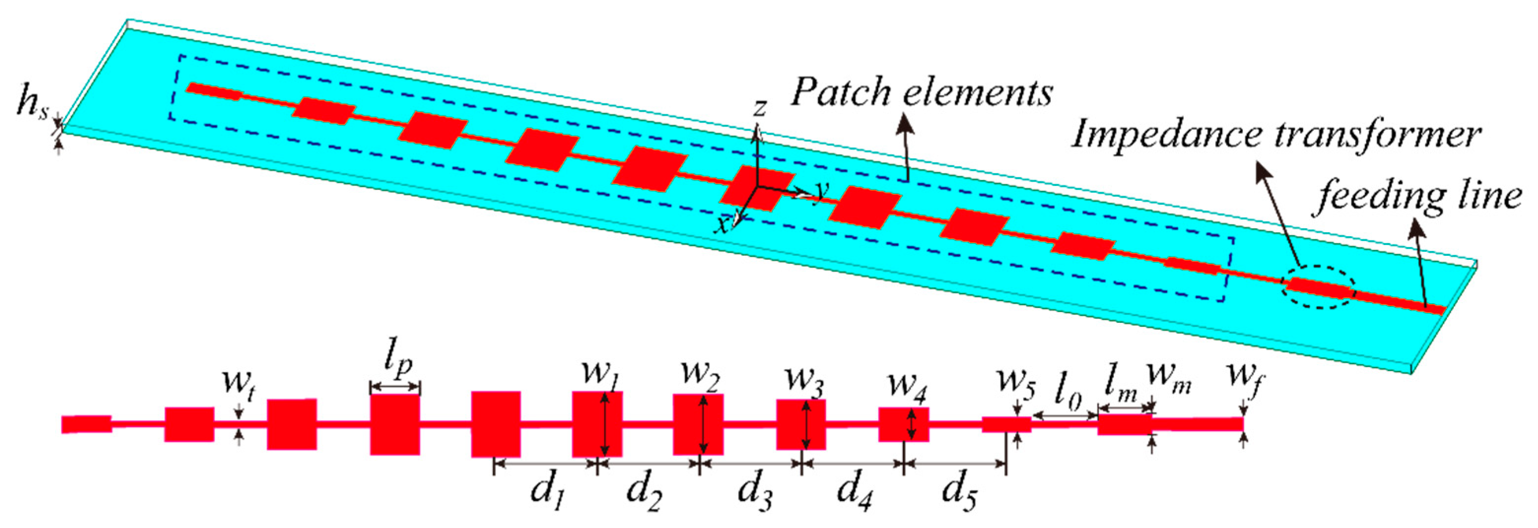
Figure 1. The geometry of the low SLL, linear series-fed patches sub-array.
Remotesensing 14 03597 g001
Figure 2. The framework of HFSS-MATLAB joint optimizing platform.
Remotesensing 14 03597 g002
Figure 3. Simulated results of the series−fed patch array. (a) Reflection coefficient and gain. (b) Pattern at 78 GHz. (c) Pattern at 79 GHz. (d) Pattern at 80 GHz.
Remotesensing 14 03597 g003
Figure 4. The geometry of the designed series feeding network. (The impedance of the input and outputs are 50 Ω. The p denotes power.).
Remotesensing 14 03597 g004
Figure 5. Three types of structures required to design the series feeding network and their corresponding equivalent circuit models.
Remotesensing 14 03597 g005
Figure 6. The simulated results of the feeding network. (a) S−parameters. (b) Output phases.
Remotesensing 14 03597 g006
Figure 7. The high surface impedance can be formed by square metal pins in two−dimensional, a bed of nails. (a) The geometry of the bed of nails. (b) Equivalent lumped circuit model.
Remotesensing 14 03597 g007
Figure 8. The evolution process of the ridge gap waveguide.
Remotesensing 14 03597 g008
Figure 9. The geometry of the unit cell and its dispersion diagram (g = 0.2 mm, d = 0.7 mm, a = 0.4 mm, p = 1.1 mm).
Remotesensing 14 03597 g009
Figure 10. The effect of the unit cell dimensions on the stopband. (a) high d . (b) gap g . (c) interval p . (d) pin width a .
Remotesensing 14 03597 g010
Figure 11. The configuration of the proposed low-SLL planar array. (a) 3-D view. (b) Side view.
Remotesensing 14 03597 g011
Figure 12. The full-wave extracted magnitude of the electric field in a plane above the GCPW feeding network. (a) Without the bed of nails. (b) With the bed of nails.
Remotesensing 14 03597 g012
Figure 13. The radiation pattern with and without the bed of nails. (a) E−plane. (b) H−plane.
Remotesensing 14 03597 g013
Figure 14. The radiation pattern of the proposed array and the radiation pattern of the planar array with the common package of a metal box. (a) E−plane. (b) H−plane.
Remotesensing 14 03597 g014
Figure 15. A fabricated prototype of the proposed low-SLL planar array.
Remotesensing 14 03597 g015
Figure 16. Experimental and simulated data. (a) |S11| (b) Gain and radiation efficiency.
Remotesensing 14 03597 g016
Figure 17. The simulated radiation patterns of the proposed low SLL planar array at (a) 78 GHz, (b) 79 GHz, and (c) 80 GHz.
Remotesensing 14 03597 g017
Table 1. The dimensions of the optimized series-fed patch antenna array. (Unit: mm).
w1w2w3w4w5wmwfd1
0.320.721.081.31.410.440.32.19
d2d3d4d5lpl0lmwt
2.192.232.222.231.061.491.150.12
Publisher’s Note: MDPI stays neutral with regard to jurisdictional claims in published maps and institutional affiliations.