Article

Robust Extraction of 3D Line Segment Features from Unorganized Building Point Clouds

1
Engineering Research Center of Environmental Laser Remote Sensing Technology and Application of Henan Province, Nanyang Normal University, Wolong Road No. 1638, Nanyang 473061, China
2
School of Geodesy and Geomatics, Wuhan University, Wuhan 430079, China
3
School of Mathematics and Computer Science, Nanchang University, Nanchang 330031, China
*
Author to whom correspondence should be addressed.
Remote Sens. 2022, 14(14), 3279; https://doi.org/10.3390/rs14143279
Submission received: 8 June 2022 / Revised: 30 June 2022 / Accepted: 5 July 2022 / Published: 7 July 2022

Abstract

:
As one of the most common features, 3D line segments provide visual information in scene surfaces and play an important role in many applications. However, due to the huge, unstructured, and non-uniform characteristics of building point clouds, 3D line segment extraction is a complicated task. This paper presents a novel method for extraction of 3D line segment features from an unorganized building point cloud. Given the input point cloud, three steps were performed to extract 3D line segment features. Firstly, we performed data pre-processing, including subsampling, filtering and projection. Secondly, a projection-based method was proposed to divide the input point cloud into vertical and horizontal planes. Finally, for each 3D plane, all points belonging to it were projected onto the fitting plane, and the α-shape algorithm was exploited to extract the boundary points of each plane. The 3D line segment structures were extracted from the boundary points, followed by a 3D line segment merging procedure. Corresponding experiments demonstrate that the proposed method works well in both high-quality TLS and low-quality RGB-D point clouds. Moreover, the robustness in the presence of a high degree of noise is also demonstrated. A comparison with state-of-the-art techniques demonstrates that our method is considerably faster and scales significantly better than previous ones. To further verify the effectiveness of the line segments extracted by the proposed method, we also present a line-based registration framework, which employs the extracted 2D-projected line segments for coarse registration of building point clouds.

1. Introduction

In recent years, benefiting from the advance in sensor technology, light detection and ranging (LiDAR) technology has been rapidly developed. The increasing prevalence of 3D laser scanning equipment has resulted in a dramatic explosion in the availability of 3D point cloud data, and point clouds containing tens of millions of samples are now commonplace. However, due to the unstructured, irregular, and non-uniform characteristics of raw point cloud data, there is an ever-growing demand for concise and meaningful abstractions of point cloud data. As one of the most important features for human perception, 3D line segment structures are widely used and play an important role in many areas, such as building outline extraction [1], building model reconstruction [2,3], road extraction [4], registration [5], localization [6], calibration [7], and more. Over the past few decades, detecting line segments from 2D images has been well-studied [8,9,10,11,12], while the works on 3D line segment extraction are still insufficient. Moreover, unlike 2D images whose pixels are closely related to their neighboring pixels, unorganized point clouds lack connectivity information. It is difficult to detect 3D line segments in unstructured, huge, and inhomogeneous point clouds, and many previous approaches failed when faced with fast and accurate 3D line segment extraction from large-scale building point clouds.
A primary reason is that the definition of “line segment” is difficult to formalize with various rules because scenes in the real world are very diverse, and a perceptible line segment is actually relevant to complicated factors, such as sudden changes in curvature or color, sharp edge, plane intersection, etc. As pointed out in [13], most 3D line segment extraction methods consist of two main steps: (1) convert the input point cloud into images first, and then apply the line segment detector to extract 2D line segments on the images; (2) backproject these 2D line segments to the original coordinate system to obtain the final 3D line segments. However, these methods have high requirements on image quality and are very sensitive to noise. In this paper, we neither perform line segment extraction directly on the original point cloud nor consider strategies based on projection and back-projection. Instead, considering that line segments are closely related to planes, we propose a novel method for extraction of 3D line segment features from building point clouds based on planar features. The key idea of our method consists of three phases.
First, given the input point cloud, data pre-processing including subsampling, filtering, and projection is performed. Second, a projection-based method is proposed to divide the input point cloud into vertical and horizontal planes, which mainly includes three steps: collinear point detection, clustering, and interior point extraction. Finally, for each 3D plane, a robust plane fitting method is adopted to estimate its corresponding equation. Subsequently, the improved α-shape algorithm is exploited to extract boundary points of each plane. The 3D line segment structures are extracted from the boundary points.

1.1. Related Work

Three-dimensional line segment extraction is a long-standing, yet active topic. In the past decades, numerous methods have been developed by researchers from different fields, the most important of which can be broadly classified into four categories: point feature-based, multi-view image-based, plane feature-based, and deep learning-based methods.
Point feature-based methods: The point feature-based methods usually detect boundary or contour points first, and then use fitting methods such as least squares to extract line segments. Various kinds of features such as the Gauss Map [14], the curvature variation [15], the normal difference [16], and the features based on eigenvalue decomposition [17] have been proposed for boundary or contour point recognition. In [14], given an unorganized point cloud, Gaussian graph clustering was first computed to eliminate points that are unlikely to belong to edges, and in the second stage, a more precise iterative selection of the remaining feature points was performed to improve reliability and robustness in the presence of obtuse and acute angles. In [15], sharp edge features were detected by analyzing the eigenvalues of the covariance matrix defined by each point’s k-nearest neighbors, then the qualitative and quantitative evaluations were evaluated using several dihedral angles and well-known examples of unorganized point clouds. In [16], a novel multi-scale operator named the difference of normal (DoN) for unorganized 3D point clouds was introduced. The normal of each point was calculated in different scales, and only those with higher normal difference were selected as boundary points. Hackel et al. [17] predicted the contour score for each individual point with a binary classifier by using a set of features extracted from the point’s neighborhood. The contour scores serve as a basis to construct an overcomplete graph of candidate contours. Jarvis [18] improved the convex hull formation algorithm to allow some concavities in the extracted shape. Zhang et al. [19] proposed the 3D guided multi-conditional GAN (3D-GMcGAN) to extract contour points of outdoor scene data consistent with visual perception. In their solution, first, a parametric space-based framework is proposed via a novel similarity measurement of two parametric models. Second, a guided learning framework is designed to assist finding the target contour distribution via an initial guidance. Chen and Yu [20] presented a novel method for the generation and regularization of feature lines, which consists of two main steps: extraction of the outline points according to the property of vector distribution and cluster, feature points are sorted according to the vector deflection angle and distance, and they are fitted using an improved curve fitting method. The biggest drawback of these methods based on point features lies on the feature point itself, which is sensitive to noise interference.
Multi-view image-based methods: Another important way to perform 3D structure detection is multi-view stereo. Multi-view stereo obtains multiple images of the target object from different perspectives, and then uses mathematical reasoning and other means to reconstruct the scene. Taylor et al. [21] reconstructed the 3D line segments of a target object from multiple images captured by a moving camera under perspective projection. Recovery is formulated by minimizing the total squared image distance between measured segments and the projection of the reconstructed infinite lines with respect to structural and motion parameters. Martinec et al. [22] recovered 3D line segment structure in multi-view images by decomposing a matrix containing line correspondences. This scheme does not use the point correspondence so as to achieve a better reconstruction effect. In [23], 3D line segments that represented the underlying geometrical characteristic of 3D objects in the area to be detected were reconstructed by evaluating the conditions determined by connectivity constraints and depth information. In the approach proposed by Lin et al. [24], 3D line segments were extracted by combining shaded images and point clouds, which were capable of accurately extracting plane intersection line segments from large-scale raw scan points. In early research, 3D scanning equipment was expensive and difficult to obtain; thus, 3D models were often obtained by this manner. The multi-view image-based methods are more suitable for data collected from a single perspective. However, it is powerless to process the data collected by multiple stations. For example, the scene of the indoor building point cloud collected by the backpack-type 3D laser scanner is relatively complex. If it is multi-view projected, the line segment information in the images will cover and overlap each other, resulting in the failure of these algorithms.
Plane feature-based methods: The third class of techniques used to identify 3D line segments in point clouds is based on plane features. The plane structure is often accompanied by the 3D line segment structure. Therefore, it is a feasible method to extract the plane structure first, and then perform the line segment extraction on this basis. In [25], unlike traditional methods which usually extract contour points first and then link them to fit for 3D line segments, 3D line segments were detected based on point cloud segmentation, 3D-2D projection and 2D-3D re-projection. Lin et al. [1] presented a new processing flow to reconstruct line segments from a large-scale point cloud scenario. The key was to segment the input point clouds into a collection of facets efficiently. Particularly, the concept “number of false alarms” was introduced into 3D point cloud context to filter the false positive line segment detections. Sampath et al. [26] presented a framework for the reconstruction of polyhedral building roofs collected from airborne laser point cloud scanning equipment. Three-dimensional line segments at the intersection of the roofs are first extracted, then these structures were used for the reconstruction of polyhedral building roofs. In [7], 3D line segments were extracted via plane intersection. The proposed method recovered line structures in the scenarios to precisely determine the rigid transform. The common drawback of these methods is that it is not easy to determine the endpoints of the extracted line segments. Moreover, the plane-based methods are more suitable for large planes and less sensitive for small planes.
Deep learning-based methods: In recent years, with the continuous breakthrough of basic science and the upgrade of computer software and hardware, various deep learning methods have emerged and are applied to different fields, which has greatly changed the traditional way of life and production. Deep learning has demonstrated extraordinary performance and achieved notable success in 2D image processing [27,28,29]. However, due to the high redundancy, uneven density distribution, nonlinear error, and large amount of data of point clouds, it is still difficult to perform convolution operations on unstructured point cloud data directly. Hackel et al. [17] proposed a learning-based contour point extraction method for building a point cloud, where each point is first predicted with a classifier. Then, the optimal set of contour points is selected by solving high-order MRFs. PointNet [30] opened a deep learning framework that performs directly on unstructured point clouds. PointNet++ [31] extended PointNet for local region computation by applying PointNet hierarchically in local regions, and many state-of-the-art methods have been developed since then [32]. Inspired by recent point cloud learning networks, Yu et al. [33] first proposed the method of contour point extraction based on deep learning theory. The proposed framework was specially designed to manipulate points grouped in local patch sets, and trained to learn consolidated points. Zhang et al. [19] proposed the 3D guided multi-conditional GAN (3D-GMcGAN) to extract contour points of outdoor scene data consistent with visual perception. Subjected to limited samples, the method based on deep learning for linear structure extraction can only extract the contour lines consistent with the marked samples. However, real-world scenes are very complex, and limited manually labeled samples are not enough to identify diverse contour or edge points.
As discussed above, the drawback of the point feature-based methods is that the extracted feature points are sensitive to noise, which easily leads to omission or misidentification. The method based on multi-view images is easily affected by the image quality, and is more suitable for point cloud data in a simple scene collected from a single view angle. The disadvantage of the plane-based methods is that it is more suitable for processing larger planes, while is less effective for small planes. Deep learning-based methods are highly dependent on labeled samples. Since this paper is mainly for 3D line segment information extraction of artificial buildings, and these artificial buildings contain many large facades and horizontal planes, it is reasonable to adopt the plane-based method. However, plane segmentation is not a simple task, as the point clouds are unstructured and often massive. Numerous previous techniques are computationally expensive and do not scale well with the size of the datasets [34]. In order to overcome some defects of traditional plane segmentation algorithms, such as low efficiency, over-segmentation, under-segmentation, uncertainty, etc., a new plane segmentation framework for building point cloud is proposed. Subsequently, 3D line segments are extracted based on these planes, followed by a 3D line segment merging procedure.

1.2. Contribution

The main contributions of our work are summarized as follows:
(1)
A 3D line segment extraction method for building point clouds is proposed, which is conceptually simple and easy to implement. The proposed method only uses the original point cloud, and does not require the images or reconstructed models;
(2)
The multiple constraints in the algorithm filter out a lot of irrelevant debris, which means that the proposed method can restore detailed information more accurately, and greatly reduces the misidentification of 3D line segments;
(3)
The proposed method transforms the problem of structure line detection in 3D space into 2D space, and most operations are mainly carried out in 2D space, hence the algorithm proposed in this paper is very efficient;
(4)
The 3D line segment extraction method can be flexibly combined with other plane segmentation methods. The method can simultaneously detect 2D and 3D line segments without changing the model structure;
(5)
The proposed method works well in both high-quality TLS and low-quality RGB-D point clouds, and is robust to noise.
The rest of this paper is organized as follows: detailed algorithms of the proposed method are presented in Section 2. In Section 3, the experiments are described, experimental results are demonstrated, performance comparison is performed, and discussions are provided. Finally, conclusions and recommendations are provided in Section 4.

2. Materials and Methods

To overcome some of the above-listed deficits, a new 3D line segment extraction method is proposed, which is conceptually simple and easy to implement. The proposed method consists of three phases, including data pre-processing, plane segmentation and 3D line segment extraction (see Figure 1). Considering that man-fabricated buildings contain a large number of facades and horizontal planes, the projections of these planes in specific directions are densely distributed linearly. Therefore, once we obtain the exact positions of the projected line segments, the spatial geometric equations of the corresponding planes are also determined, and the plane interior points can be easily extracted using these equations. However, for the large-scale point clouds, which are acquired by the current variety of LiDAR systems, they also bring a great challenge in data processing. To improve operational efficiency, appropriate data cropping and subsampling are necessary. In the first phase, provided the input point cloud, we perform data pre-processing including subsampling, filtering, and projection. In the second phase, a projection-based method is proposed to divide the input point cloud into vertical and horizontal planes, which mainly includes three steps: collinear point detection, clustering, and interior point extraction. Finally, for each 3D plane, a robust plane fitting method based on Principal Component Analysis (PCA) is adopted to estimate its corresponding equation. Subsequently, the improved α-shape algorithm is exploited to extract boundary points of each plane. The 3D line segment structures are extracted from the boundary points, followed by a 3D line segment merging procedure.

2.1. Data Pre-Processing

Considering that the building point clouds contain a large number of plane structures, especially the vertical and horizontal planes, the paper proposes a projection-based plane segmentation method. Based on the fact that the projection of the facade on the X-Y plane and the projection of the horizontal plane on the X-Z plane are linearly distributed, we first performed the following data pre-processing steps before 3D structure line extraction (see Figure 2).
Subsampling: Building point clouds are usually very dense and massive, and operating directly on the raw data is not only time-consuming but may also lead to computational failures. Therefore, proper subsampling is necessary because it does not affect the linear distribution of plane projections in the building, and the computational efficiency is greatly improved due to the reduction in the amount of data. Porig is the input point cloud, a subsampling threshold ε 1 is set as the min distance between two points, and then Porig is uniformly subsampled to ensure that the distance between any two points is not less than ε 1 . The subsampled point cloud is represented as Psub. As shown in Figure 3, although the number of points in the original point cloud was drastically reduced from 27,484,853 to 44,541, the part of the facade projected to the ground is still densely linearly distributed and the average point distance is 0.018 m.
Filtering: As shown in Figure 3, the horizontal plane projected to the X-Y plane presents a scattered distribution, which is undoubtedly not conducive to the subsequent line segment extraction. Therefore, it is necessary to remove the horizontal plane before the elevation extraction. Here, we propose a statistical-based plane removal method. As shown in Figure 4, we propose a statistical-based plane removal method. As shown in Figure 4, taking a real indoor scene as an example, the sampled indoor point cloud contains four main horizontal planes. According to a certain step size (e.g., 0.05 m), the distribution histogram of Psub along the Z direction is calculated. It can be seen that the histogram contains four main peaks corresponding to floor, bed, and secondary ceiling, in the Z direction (see Figure 5). To take advantage of this remarkable feature, the main horizontal plane can be roughly removed by eliminating points within a certain range of the peaks. The filtered point cloud is denoted as Pfilt.
Projection: Next, Pfilt is projected onto the X-Y plane via the following equation:
ax + by + cz + d = 0
where a = b = d = 0, and c = 1. The output point cloud after pre-processing is denoted as Pproj.

2.2. Plane Segmentation

Collinear point detection: The shadows of walls and other vertical planes in Pproj are distributed in dense linear patterns. Next, line segments need to be extracted from Pproj. Although Pproj is a 2D point cloud data (Z coordinate equal to 0), it is still regarded as a 3D point cloud during the line segment extraction process. Once the line segments are accurately detected, the corresponding vertical plane positions are also determined. In practice, the Random Sample Consensus (RANSAC) algorithm [35] is particularly effective for line detection in the following two aspects: (1) It is easily extensible and straightforward to implement. (2) It can robustly deal with point clouds containing a lot of noise. Although Pproj is a 2D dataset (the z coordinate of each point is 0), in the line segment detection algorithm, it is considered as a 3D point cloud data.
As shown in Figure 6, RANSAC performs line detection iteratively by randomly choosing two points A (xa, ya, za) and B (xb, yb, zb) (since at least two points are required to determine a line). The line L defined by A (xa, ya, za) and B (xb, yb, zb) can be expressed as:
x x a x b x a = y y a y b y a = z z a z b z a = t
Suppose that there is a plane ψ c passing through point P (xp, yp, zp) and taking the direction A B as its normal vector. C (xc, yc, zc) is the intersection of ψ c and L. Then each coordinate value of point C (xc, yc, zc) can be calculated as follows:
x c = x b x a × t + x a y c = y b y a × t + y a z c = z b z a × t + z a
Based on the fact that CPAB, t can be expressed as:
  t = x p x a x b x a + y p y a y b y a + z p z a z b z a x b x a 2 + y b y a 2 + z b z a 2
The distance dpc between P (xp, yp, zp) and C (xc, yc, zc) is calculated as:
d p c = x p x c 2 + y p y c 2 + z p z c 2
A distance threshold ε 2 is set as the maximum offset of a line when performing the RANSAC algorithm, and ε 2 is usually associated with the average point distance daver of Pproj. For each point qi in Pproj, a neighborhood search is performed to find its neighboring points (denoted as qi1, qi2,…, qik). Daver is calculated as:
d a v e r = 1 N i = 1 N d a v e r i d a v e r i = 1 k j = 1 k q i q i j
where N is the point number of Pproj. For efficiency, k is usually set to 2 based on previous experiences.
Then the number of points lie on the line defined by A (xa, ya, za) and B (xb, yb, zb) is counted. The maximum number of iterations for detecting a line is set to ε 3 . After a given number of trials, a set of collinear points Pcol with a maximal score is extracted. However, as shown in Figure 7a, the RANSAC algorithm cannot be used directly in our application. The first reason is that some spurious lines were generated due to the random nature of RANSAC. Second, RANSAC can only distinguish those collinear points. When facing with points that are collinear but not continuous, it becomes powerless. Third, it is difficult to ascertain the appropriate convergence conditions.
Clustering: To overcome some of the deficits listed above, an adjusted Euclidean clustering method is adopted to split Pcol into separated segments (if necessary). A distance threshold ε 4 is defined as the farthest distance to determine whether two adjacent points lie on the same line segments. Suppose that there are two subsets PI and PJ in Pcol, and PIPJ = Ø. The two subsets are considered to belong to different line segments via the following condition:
min p i P I , p j P J p i p j > ε 4
The detailed clustering process is as follows:
(1)
The kd-tree structure is used to manage Pcol. An empty cluster list E and a pending queue Q are established. Then each point in Pcol is added into Q;
(2)
For each point Qi in Q, a neighborhood search is performed on it and the searched points are stored in Qik. For each point in Qik, the distance dik between it and Qi is calculated. If dik   ε 4 , the corresponding point will be stored in E along with Qi;
(3)
The distances between all the clusters in E are calculated according to Equation (6), and the clusters that are less than ε 4 apart from each other are merged. The merging process iterates until all the distances between clusters are greater than ε 4 ;
(4)
If the clustering results are not empty, the results are stored in Pseg. For each subset Psegi in Pseg, its length Lsegi and point number Nsegi are calculated. A threshold ε 5 is set as the minimum number of points per meter. A threshold ε 6 is set as the shortest distance of a qualified line segment. If Nsegi/Lsegi ε 5 and Lsegi ε 6 , Psegi is stored as a qualified line segment. Then all qualified line segments in Pseg are removed from Pproj;
(5)
The remaining points are invoked as input data, and the next cycle is continued. The iteration ceases when the qualified clustering results are null for five consecutive times. On the other hand, to make the program converge as quickly as possible, when the remaining points are less than a specified percentage (e.g., 5%) of the input data Pproj, the iteration is also forced to end. The extracted qualified line segments are stored in Pqual (see Figure 7b).
Interior point extraction: For each qualified line segment Pquali in Pqual, the endpoint coordinates are obtained as E (xs, ys, 0) and F (xe, ye, 0). The spatial geometric equation of the corresponding elevation ψ v can be expressed as:
x i x e x s y e y s × y i + x e × y s x s × y e y e y s = 0  
The distance d i v between a spatial point and the façade ψ v defined by Equation (8) is calculated as:
d i v = y e y s × x i x e x s × y i + x e × y s x s × y e y e y s 2 + x e x s 2
For each point in Porig, the distance div from it to ψ v is calculated according to Equation (8). If div ε 2 , the corresponding point is stored as a coplanar point. To obtain more precise plane segmentation results, another two planes, ψ s and ψ e , are designed which both use direction E F as their normal vector and pass through the endpoint coordinates E (xs, ys, 0) and F (xe, ye, 0), respectively. The two equations of ψ s and ψ e are defined as:
x e x s x i x s + y e y s y i y s = 0 x e x s x i x e + y e y s y i y e = 0
For each point in the coplanar points Pcop, the distance values from dis and die to ψ s and ψ e are calculated, respectively. If dis + die > dse, the corresponding point is removed from the coplanar points. Note that dse denotes the distance between ψ s and ψ e . The coplanar points after preliminary filtering are denoted as Pfilt. To avoid accidentally extracting points on the ground and ceiling, calculating the minimum value Zmin and the maximum value Zmax of Porig in the Z-axis direction is necessary, and points whose z coordinates are greater than Zmax ε 2 or less than Zmin + ε 2 are excluded from Pfilt. Pvert is the final filtered coplanar points, and Pvert is output as a vertical plane. All qualified line segments are used to extract their corresponding vertical planes (see Figure 8a). For efficiency, all points in the vertical planes are removed from Porig. Prem is the remaining points (see Figure 8b). As shown in Figure 8b, the remaining points are mainly composed of some horizontal planes such as floor, ceiling, etc. Similar to the steps above, after pre-processing, Prem is used to extract the horizontal plane Phor (see Figure 8c). Note that Prem is projected onto the X-Z plane. Finally, the extracted planes are merged (see Figure 8d).

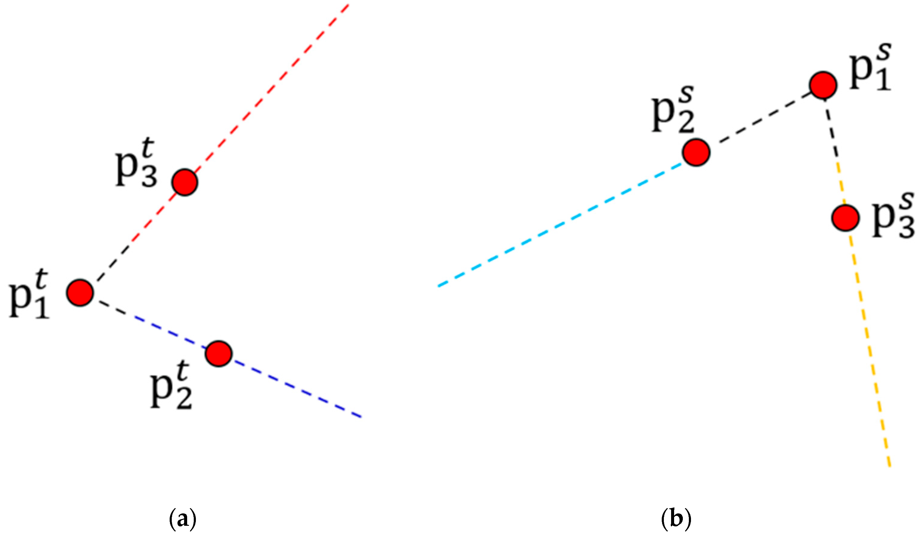
2.3. Three-Dimensional Line Segment Extraction

After plane segmentation, the α -shape algorithm is exploited to extract boundary points of each plane. In general, it is a method of abstracting the edges of discrete point sets. If that there is a finite set of discrete points S, the principle can be imagined as a circle with a radius of ε 7 rolling outside the point set S. The circle passes through any two points in S, if there are no other points in this circle, the two points are considered to be boundary points [36]. The boundary points are extracted by iteratively detecting such circles. However, as shown in Figure 9a, the surface of the input data contains a lot of noise, such as a wall with a certain thickness. No matter how the parameters are adjusted, the α -shape algorithm cannot extract the boundary points of the point cloud data. The purpose is to reliably extract 3D line segments for indoor point clouds, even under adverse conditions such as heavy noise; therefore, before boundary point extraction, it is necessary to process the data to make it suitable for the α-shape algorithm. A robust plane fitting method based on Principal Component Analysis (PCA) is adopted.
Plane position determination:Pplane is one of the above extraction planes. The spatial plane equation of points in Pplane is:
A x + B y + C z + D = 0
where A, B, and C are normal vectors of the plane and satisfy A 2 + B 2 + C 2 = 1 .
The distance di from a point pi on Pplane to the plane defined by Equation (11) can be expressed as:
d i = A x i + B y i + C z i + D  
where xi, yi, and zi are coordinate values of point pi.
To obtain the best fitting plane, the objective function F0 should meet the following conditions:
F 0 = m i n i = 1 N A x i + B y i + C z i + D 2
Using the Lagrange multiplier method to solve the minimum value of the objective function F0, the following functions are first composed:
F = i = 1 N A x i + B y i + C z i + D 2 λ A 2 + B 2 + C 2 + 1
where λ is the undetermined value.
Taking the partial derivative of Equation (14) with respect to D and making the derivative result 0, the following relationship can be obtained:
F D = 2 i = 1 N A x i + B y i + C z i + D = 0
Then the following relationship can be further obtained:
D = A x ¯ + B y ¯ + C z ¯
where x ¯ = 1 N i = 1 N A x i , y ¯ = 1 N i = 1 N A y i , z ¯ = 1 N i = 1 N A z i .
Equation (12) can be rewritten as follows:
d i = A x i x ¯ + B y i y ¯ + C z i z ¯
Using Equation (14) to calculate the partial derivatives of A, B, and C, respectively, the following relationship can be obtained:
i = 1 N Δ x i Δ x i i = 1 N Δ x i Δ y i i = 1 N Δ x i Δ z i i = 1 N Δ x i Δ y i i = 1 N Δ y i Δ y i i = 1 N Δ y i Δ z i i = 1 N Δ x i Δ z i i = 1 N Δ y i Δ z i i = 1 N Δ z i Δ z i A B C = λ A B C
where Δ x i = x i x ¯ , Δ y i = y i y ¯ , Δ z i = z i z ¯ .
The covariance matrix M 3 × 3 is constructed as follows:
M 3 × 3 = i = 1 N Δ x i Δ x i i = 1 N Δ x i Δ y i i = 1 N Δ x i Δ z i i = 1 N Δ x i Δ y i i = 1 N Δ y i Δ y i i = 1 N Δ y i Δ z i i = 1 N Δ x i Δ z i i = 1 N Δ y i Δ z i i = 1 N Δ z i Δ z i
The covariance matrix M 3 × 3 is always symmetric positive semi-definite [37]. Based on this characteristic, e 1 , e 2 , and e 3 are the three eigenvectors of M 3 × 3 , respectively. Λ 1     λ 2     λ 3 are the three eigenvalues of M 3 × 3 . M 3 × 3 can be decomposed as follow:
M 3 × 3 = e 1 e 2 e 3   λ 1 0 0 0 λ 2 0 0 0 λ 3   e 1 e 2 e 3
In practice, e 3 = ( α , β , γ ) is often used as the normal of Pplanei. However, the eigenvalue method directly uses all points in Pplane for plane fitting, in which the fitting parameters obtained are not optimal. To obtain more accurate fitting parameters, first, for each point in Pplanei the distance djp to the plane defined by e 3 and p ¯ is calculated, and the standard deviation σ is computed as:
σ = 1 k j = 1 k ( d j p d ¯ ) 2 d ¯ = 1 k j = 1 k d j p
If djp > 2   σ , the corresponding points are removed from Pplane, and the remaining points are used to recalculate the value of e 3 and p ¯ . For efficiency, the number of iterations is set to ε 8 empirically. After ε 8 iterations, the exact values of plane normal vectors A, B, and C are obtained, and then the value of D is obtained by using Equation (16).
As the accurate fitting parameters for each plane are obtained, the equation is provided by:
x r y r z r = 1 A 2 + B 2 + C 2   B 2 + C 2 A B A C A D A B A 2 + C 2 B C B D A C B C A 2 + B 2 C D x n y n z n 1
Contour point extraction: As shown in Figure 9b, after projection, a plane point cloud with random noise becomes very flat. Next, the α-shape algorithm is used to extract boundary points Pedge of each plane (see Figure 10b). Since the average point distance of each plane is not always the same or even very different, ε 7 is associated with the average point distance of S to achieve a good edge extraction effect.
After projecting the plane onto itself, the α-shape algorithm is used to extract boundary points Pedge of each plane (see Figure 10b). Since the average point distance of each plane is not always the same or even very different, ε 7 is associated with the average point distance of S to achieve a good edge extraction effect. A distance threshold ε 9 is set as the maximum offset of a line when performing RANSAC. The parameters remain unchanged except that ε 2 is replaced by ε 9 .
Line segment extraction: Then the line segment detection method described above is used to extract 3D line segments in Pedge (see Figure 10c). As shown in Figure 11a, the extracted 3D line segments may contain line segments that are close to each other. To make the extraction results more concise, the 3D line segment merging procedure is proposed. First, the extracted 3D line segments are sorted in descending order according to their lengths. For each sorted segment, the angle θ i j between it and another line segment is calculated. V i and V j are the normal vectors of the two 3D line segments to be compared (the normal vector of each line segment is estimated by RANSAC in advance), and θ i j is calculated as:
θ i j = a c o s V i × V j V i V j
If θ i j   < 5° or θ i j   > 175°, the two segments are considered to be approximately parallel. Note that 5° is an empirical value for judging parallel lines. Once the parallelism of two 3D line segments is checked, the corresponding pair will be marked and will not be compared repeatedly.
Second, for each parallel pair, the orthographic distances from the two endpoints of the longer line segment to the other one is calculated. If both distance values are less than 0.05 m, the two segments are considered to be approximately collinear. Note that 0.05 m is an empirical value for judging collinear lines.
Finally, the endpoints of the two 3D line segments are checked to ascertain whether there is overlapping part. The collinear segments with overlapping are considered to be merged. If a line segment is shorter than the other, only the longer one is retained. The rest is output as the final 3D line segment extraction result (see Figure 11b).

3. Experiments and Analysis

Considering that the plane segmentation involved in this paper are mainly horizontal planes and elevations, in order to evaluate the performance of the proposed method we first test it on four indoor scenes. Outdoor scenes and other buildings with sloped faces will be discussed in subsequent subsections. As shown in Figure 12, scene 1 is a stair entrance, and scene 2 is a corridor, both of which were obtained at the School of Surveying and Mapping, Wuhan University, using the terrestrial laser scanner Faro Focus 150. The two scenes are relatively representative, including indoor structures in most occasions, such as floors, walls, doors, windows, ceilings, stairs, handrails, corners, etc., as well as some sundries such as flower pots, trash cans, etc. Scene 3 is collected from the laboratory on the first floor of Wuhan Haida Digital Cloud Co., Ltd. (Wuhan, China). The instrument used is the HS500i terrestrial 3D laser scanner developed by the company. It should be pointed out that the scanning accuracy of this scanner is poor. The surface of the collected point cloud data has a lot of random noise, and the quality is not as good as the first two scenes. This scene can be used to verify the performance of the proposed algorithm in 3D line segment extraction with noise interference. Scene 4 is selected from a recreation room in Stanford.
Large 3D Indoor Spatial Dataset (S3DIS): The Large 3D Indoor Spatial Dataset (S3DIS) is created by scanning271 rooms in six areas with a Matterport camera to generate reconstructed 3D texture meshes and RGB-D images. All the algorithms in this paper are implemented using C++ and Point Cloud Library 1.12.1, executed on a PC with Intel Core i5-830H 2.3GHz CPU and 8GB RAM, and the operating system is Windows 10.

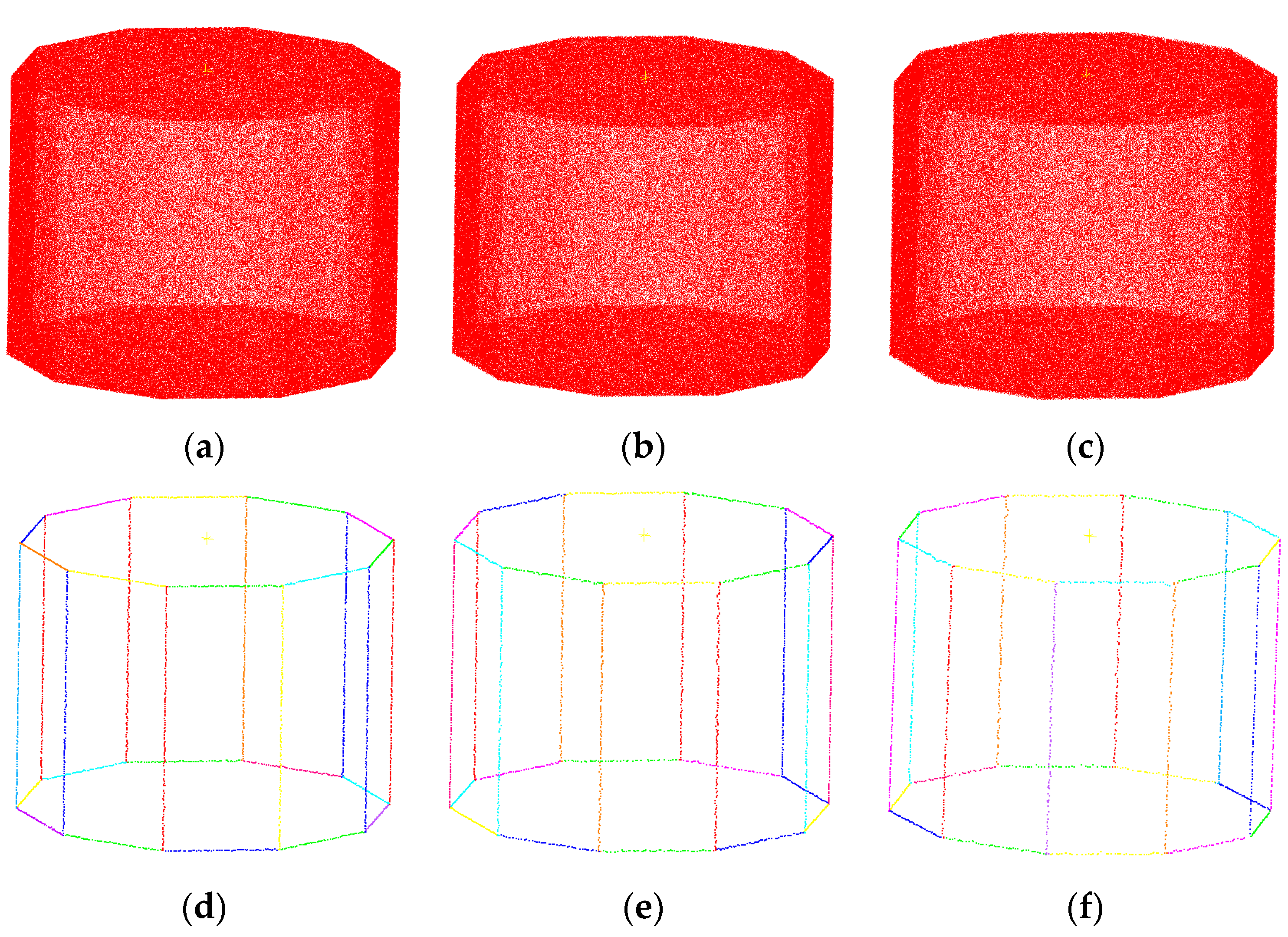
3.1. Parameters Setting

As we can see from above sections, there are generally two categories of parameters in our algorithm: number-related and distance-related. Specifically, nine parameters are involved in this paper. However, most of them are highly correlated or do not require major adjustments. Below, we provide guidelines regarding how to select these thresholds.
The subsampling threshold ε 1 represents the minimum threshold between two points, that is, after a point cloud undergoes subsampling, the distance between any two points within it is not less than ε 1 . Generally, ε 1 cannot be determined by a fixed value; rather, it depends on the scale of the original point cloud data and the noise level. For point cloud with a relatively large height span range (e.g., greater than 5 m), such as scene 1, ε 1 is set to 0.1 m; while for point clouds with a relatively small height span range (e.g., less than 5 m) such as scene 2, scene 3, and scene 4, ε 1 is set to 0.05 m. ε 2 denotes the distance threshold to determine whether a point lies on a straight line, and ε 2 is usually associated with the average point distance daver of Pproj. Here, we estimate ε 2 through statistical analysis, i.e., ε 2 is set to five times the average point distance daver of Pproj. This value works well on a broad spectrum of datasets. ε 3 is the number of iterations when performing RANSAC, which is usually set to 100. ε 4 is defined as the farthest distance to determine whether two adjacent points lie on the same line segment. For the sake of convenience, we simply set it to be four times ε 2 . ε 5 is set as the minimum number of points per meter, and ε 5 = 30 works for most scenes. ε 6 is set as the shortest distance of a qualified line segment. ε 6 = 0.2 m is an appropriate value depending on numerical experimentation.   ε 7 denotes the radius value when performing edge point extraction, and ε 7 is set to 0.5 times ε 4 . As to the remaining parameters, ε 8 is set to 5, and ε 9 is set to 10 times the average point spacing of Pedge. It is worth mentioning that fine-tuning these parameters for different types of point clouds can lead to better results.

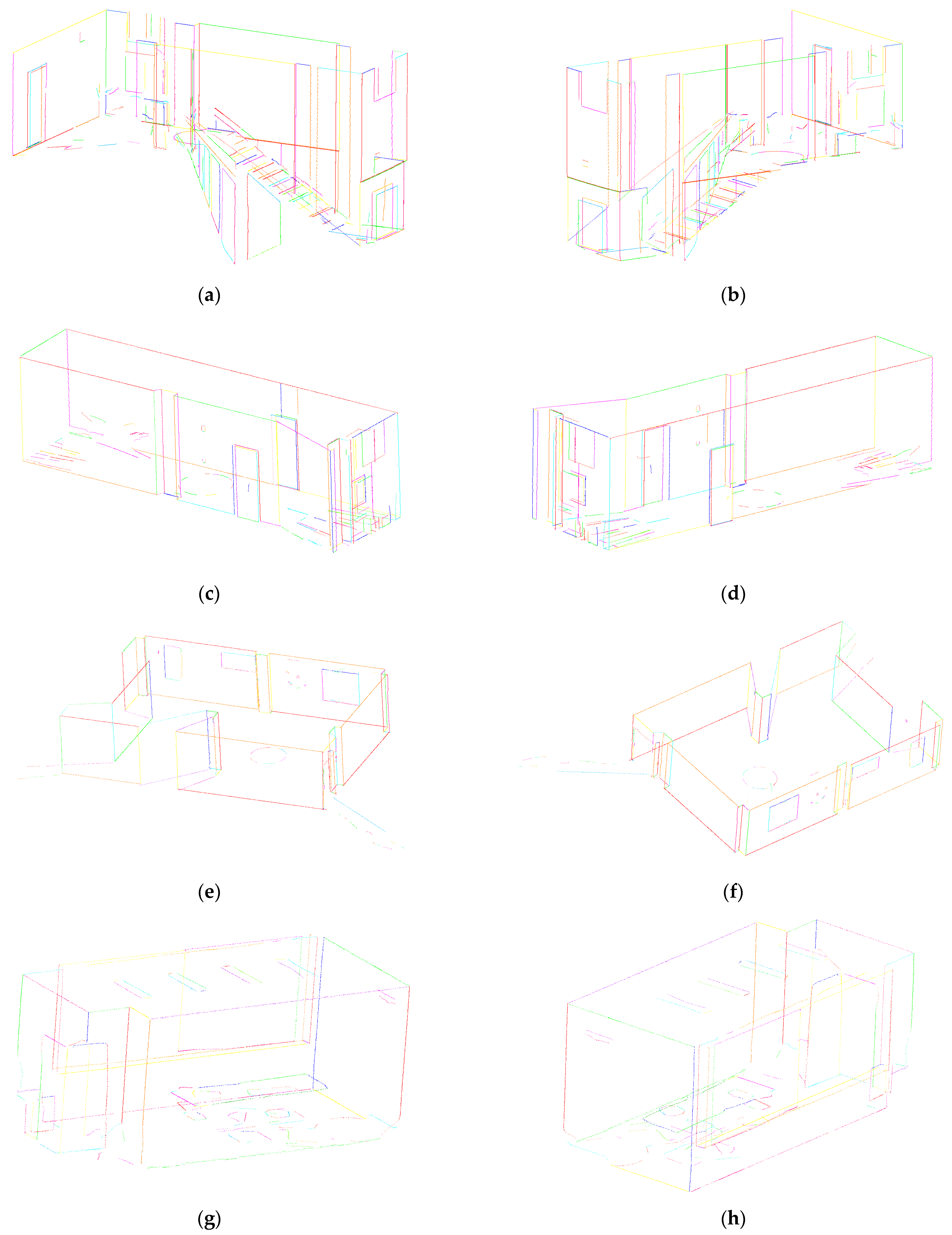
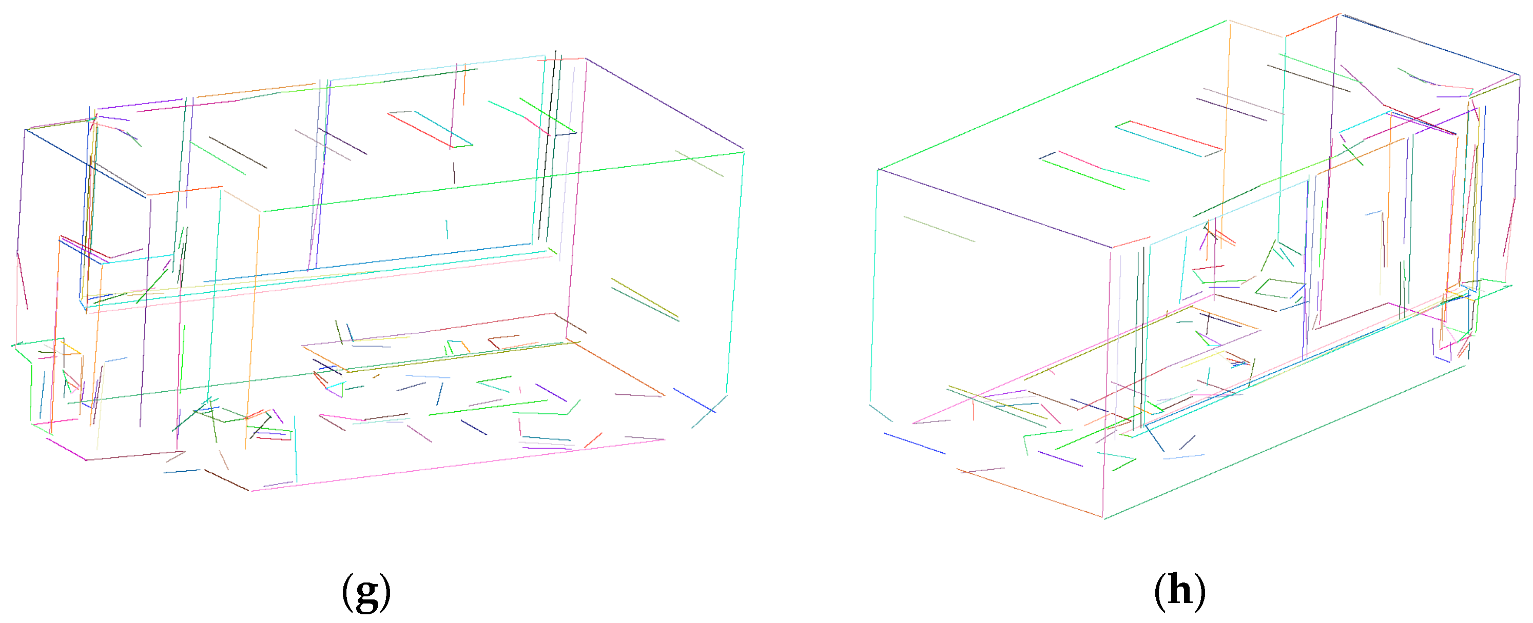
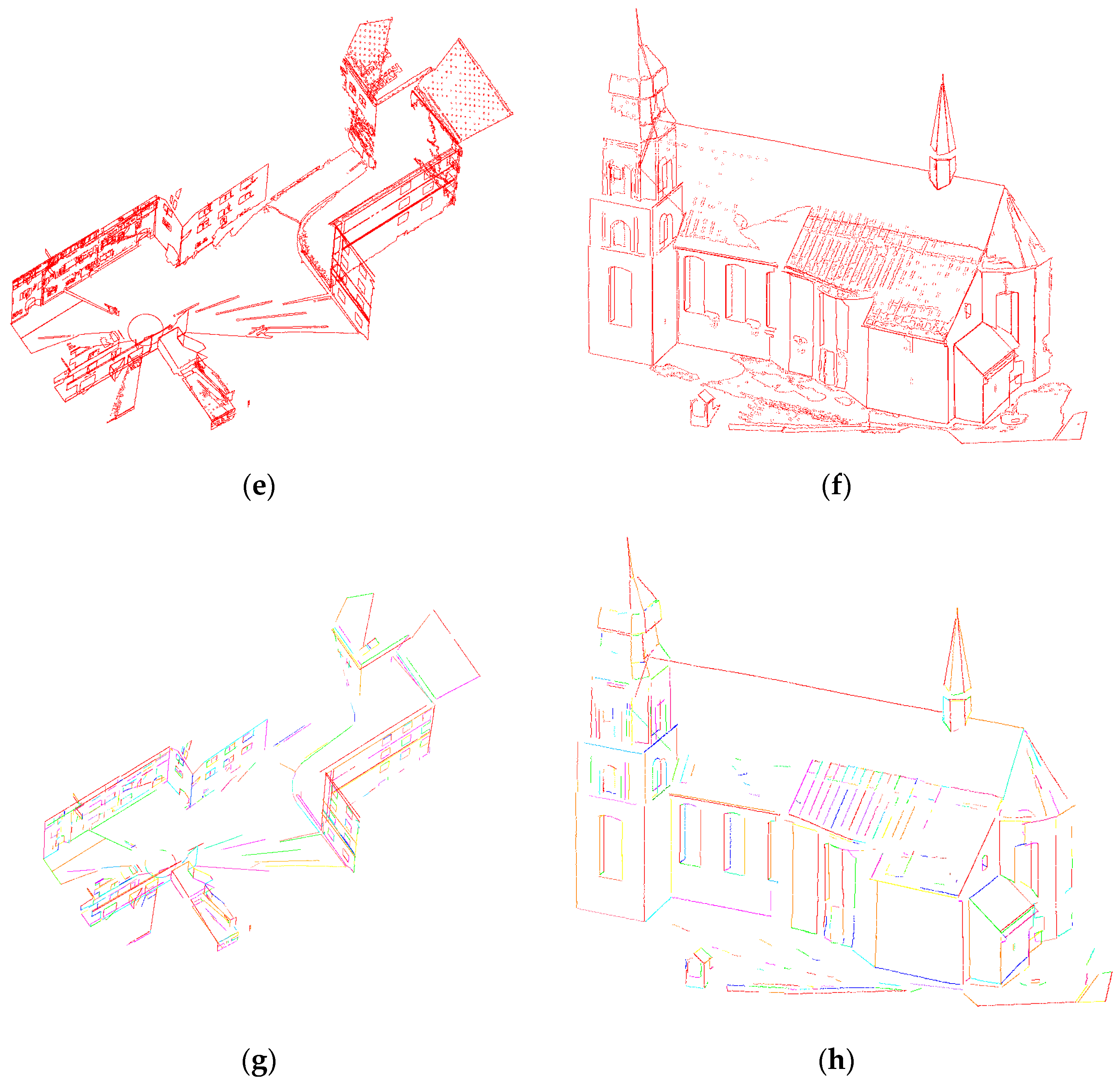
3.2. Three-Dimensional Line Segment Extraction Effect Evaluation

Considering that the plane segmentation involved in this paper are mainly horizontal planes and elevations, in order to evaluate the performance of the proposed method we first test the building point clouds of four indoor scenes. Outdoor scenes and other buildings with sloped faces are be discussed in subsequent subsections. As shown in Figure 12, scene 1 is a stair entrance, and scene 2 is a corridor, both of which were obtained at the School of Surveying and Mapping, Wuhan University, using the terrestrial laser scanner Faro Focus 150. The two scenes are relatively representative, including indoor structures in most occasions, such as floors, walls, doors, windows, ceilings, stairs, handrails, corners, etc., as well as some sundries such as flower pots, trash cans, etc. Scene 3 is collected from the laboratory on the first floor of Wuhan Haida Digital Cloud Co., Ltd. The instrument used is the HS500i terrestrial 3D laser scanner developed by the company. It should be noted that the scanning accuracy of this scanner is poor. The surface of the collected point cloud data has a lot of random noise, and the quality is not as good as the first two scenes. This scene can be used to verify the performance of the proposed algorithm in 3D line segment extraction with noise interference. Scene 4 is selected from a recreation room in the Stanford Large 3D Indoor Spatial Dataset (S3DIS). The dataset is created by scanning271 rooms in six areas with a Matterport camera to generate reconstructed 3D texture meshes and RGB-D images.
Figure 13 shows the 3D line segment structures extracted by the proposed method. In order to display more detailed information, each scene is displayed from two different angles. It can be seen that both large frames (such as floors, ceilings and walls, etc.) and details (such as doors, windows, and stairs, etc.) are recovered well, and the connections between line segments are also well-matched. The multiple constraints in the algorithm filter out a lot of irrelevant debris, so that a clear and concise extraction result can be obtained. The extracted 3D line segments are consistent with the actual contours of the experimental point cloud. As shown in Figure 13g,h, since the original input data are relatively sparse, the distances between points in the extracted line segments are relatively large. If necessary, it can be interpolated based on cubic B-spline curves. In order to preserve the authenticity of the original data as much as possible, this paper does not fit or connect the extracted line segments, thus resulting in the appearance of some “curve segments”. Table 1 shows the calculation results of the method in this paper on each dataset. The results show that the method successfully extracts the main 3D line segments within an acceptable time, and the data volume of the four original point clouds is compressed to 0.00753, 0.00304, 0.00518, and 0.01027 times the original, respectively. Although the original point cloud is greatly compressed, the basic frame and detailed information of the scenes is well-preserved, which is undoubtedly beneficial for subsequent applications such as registration, localization, object recognition, etc.
In order to further verify the accuracy of the 3D line segment extraction of the method in this paper, the accuracy of partially representative walls, doors, windows, and quadrangular prism structures of the four scenes is evaluated, respectively. The accuracy evaluation index is adopted here, that is, the accuracy is equal to the extracted area divided by the measured area. As shown in Table 2, after comparing the results obtained by the proposed algorithm with the measured data, it can be found that the extraction accuracy for the side lengths of structures such as doors, windows, and large walls is basically controlled within 5 cm. The overall accuracy of the results is basically controlled above 96%, which proves that the proposed algorithm is reliable in precision control.
In order to further verify the performance of the method proposed in this paper, it is compared with the recent work of Lu et al. [25]. The comparison results are shown in Table 1, and Figure 13 and Figure 14. As can be seen in Figure 13 and Figure 14, our detection results are at least as good as the method of Lu et al. [25], both of which are able to extract the main frame of a building. Since the first three scenes are all collected by terrestrial 3D laser scanners, the point cloud density distribution is not uniform, while the method by Lu et al. [25] uses region growing and region merging to segment the point clouds into 3D planes. These planes are then projected into corresponding 2D images, and the line segments are extracted from the images and backprojected to the planes. Image-based methods are sensitive to noise and cannot adapt well to uneven distribution of point cloud density. As can be seen from Figure 14, the method of Lu et al. [25] extracts some pseudo-line segments that do not exist, and the extracted 3D line segments are relatively cluttered with large gaps between adjacent line segments. In contrast, the method proposed in this paper can better restore 3D detail information and avoid many misidentification phenomena. As shown in Table 1, the method proposed in this paper is more efficient than the method of Lu et al. [25]. This is because the projection-based plane segmentation strategy mainly processes the point cloud in 2D space, which can quickly and accurately obtain the positions of the elevation and the horizontal planes, so as to realize the rapid segmentation of the planes. In contrast, the method of Lu et al. [25] requires time-consuming operations such as normal vector estimation, region growth, region merging, etc. The efficiency is not as high as that of the algorithm in this paper. Furthermore, the method by Lu et al. [25] extracts more planes and lines than our method because it uses an over-segmentation strategy to over-segment the point cloud into many facets.
To demonstrate the effect of contour point extraction, the proposed method is compared with Bazazian et al. [15], Ioannou et al. [16] and methods based on Statistical Outlier Removal (SOR) filtering in PCL [38], respectively. As shown in Figure 15a,e,i,m, the contour points extracted by the proposed method are clear and complete, consistent with the basic frame of the building. As shown in Figure 15b,f,j,n, Bazazian et al. [15] detected sharpness by analyzing the eigenvalues of the covariance matrix defined by the k-nearest neighbors of each point edge features. This method has better detection effect for areas with large curvature changes such as plane intersections, but cannot detect the edges of individual planes (see Figure 15b,f). This type of eigenvalue-based method is particularly sensitive to noise. As mentioned above, the point cloud quality of scene 3 is not as good as the other three, and the surface is filled with a lot of random noise, so many points on the plane are detected by mistake (see Figure 15g). As shown in Figure 15c,g,k,o, Ioannou et al. [16] calculated the normal vector of each point at different scales, and those points whose normal vector differences are greater than the set threshold are regarded as contour points. Similar to the method based on eigenvalues, this method is highly recognizable for sharp edge points, and also cannot detect edge points of a single plane (see Figure 15c,g). However, the robustness of the method proposed by Ioannou et al. [16] is better than that based on eigenvalues. As shown in Figure 15k, although the surface of the point cloud contains a lot of random noise and the density distribution is uneven, the main contour points are still accurately extracted. In short, the method based on normal differentiation can extract the rough outline of the target object, but the extraction effect is not as fine as the method in this paper. As shown in Figure 15d,h,l,p, the method based on SOR filtering has great limitations, the requirements for the quality of point cloud data are high, and the threshold parameters are not easy to accurately estimate. Table 3 shows the calculation results of the four methods for the four scenarios. It can be seen that the method in this paper has high efficiency and high data compression ratio, and is suitable for fast and fine contour point extraction in large-scale high-density building scenes.
In order to test the performance of this method in outdoor scenes, we selected Birdfountain and Bildstein from the large-scale point cloud dataset Semantic3D for experiments. Before the test, the original point clouds were appropriately cropped to filter out irrelevant content. It should be noted that the Semantic3D dataset uses terrestrial laser scanners to scan scenes such as churches, streets, railway tracks, squares, villages, football fields, and castles, and semantically label over 4 billion points. As shown in Figure 16a,b, the scene Birdfountain is taken from a street, including the street façade, sloping roofs, ground, trees, and a large number of outliers. The scene Bildstein is a Church building with numerous closely spaced facades, sloping roofs, and some arcuate structures. The plane segmentation algorithm provided in this paper is only suitable for elevation and horizontal planes. The advantages are high efficiency, good robustness, and quick processing of large-scale and high-density scene point clouds. Therefore, the proposed method is used to extract the elevation and horizontal planes, and then the improved RANSAC algorithm proposed by Chum et al. [35] is used to detect the inclined plane and some smaller planes within the remaining point cloud (see Figure 16c,d). Then the contour points are identified (see Figure 16e,f) and the 3D line segments are extracted (see Figure 16g,h). Table 4 shows the calculation results of the two outdoor scene data. It can be seen that the method in this paper can efficiently perform plane segmentation, contour point extraction and 3D line segment extraction. While retaining the main structure of the building, the data are greatly compressed.
In order to test the performance of the method proposed in this paper under different noise levels, as shown in Figure 17, a model named 101-prism in the public dataset Digital Shape Repository was selected for testing. The size of the model is 20.00 m × 19.02 m × 15.00 m, 475,250 points were uniformly sampled from this model, and 0.01 m, 0.03 m, and 0.05 m of Gaussian noise were added, respectively. It can be seen from the extraction effect that the method in this paper has good robustness and can accurately extract the 3D line segment structure under heavy noise.

3.3. Application

The 3D line segment extraction method proposed in this paper can be applied to the coarse registration of point clouds. Although terrestrial laser scanners can obtain fine 3D information on the surface of objects, the point cloud data collected from a single perspective is not enough to cover the entire scene. Therefore, it is necessary to register the point clouds collected from multiple perspectives to the same coordinate system. The process includes two steps: coarse registration and fine registration. Fine registration usually adopts the iterative nearest point (ICP) algorithm [39] or its variants [40,41]. At present, there are a large number of coarse point cloud registration methods [42,43,44], these methods calculate transformation parameters by extracting different geometric features (point, line, plane, and specific object). In general, point-based approaches are more general because they are applicable to a variety of scenarios. The methods based on lines or planes are more robust to noise and point density variation. For scenes with man-fabricated objects, extracting line/surface features for point cloud registration is a good choice due to the large number of line and surface features in the scenes. However, most existing line-based or plane-based methods use 3D lines/3D planes for point cloud registration, which means that these methods process point cloud data in 3D space. Considering that it is time-consuming to extract 3D lines/3D planes, 2D-projected line segments are used here for coarse registration of point clouds.
Assume that the point cloud to be registered is Ps and the target point cloud is Pt, the purpose of registration is to convert Ps to the coordinate system where Pt is located. Considering the leveling operation is carried out when Ps and Pt are collected by terrestrial laser scanner, the coordinate transformation mainly involves rotation and translation in X-Y plane and translation along Z axis. The intersection of planes often exists in the point cloud of buildings, and the projections of these planes on the X-Y plane are distributed as intersecting line segments. This paper fully describes the algorithm of how to extract 2D-projected line segments, and does not repeat them here.
After the projection line segments of Ps and Pt on the X-Y plane are extracted, the corresponding line segment pairs are identified (there may be more than one pairs). Although these line segment pairs have different points and may not intersect (affected by occlusion and parameter settings), their relative relationship remains unchanged, and the parameter settings among different stations are consistent, so there is no point cloud scaling phenomenon. Based on these characteristics, 2D-projected line segments can be used for registration on the X-Y plane.
Suppose the point of intersection of two intersecting lines is pinters (c1, c2), and a virtual point on the line with a length r from the intersection is p (x, y), then the following relationship can be obtained:
y = a 1 x + b 1 x c 1 2 + y c 2 2 = r 2
where a1 and b1 are the parameters in the rectangular coordinate system.
Substituting the first term in Equation (24) into the second term, the value of x can be obtained as:
x = B ± B 2 4 A C 2 A
where
A = 1 + a 1 2 B = 2 a 1 b 1 a 1 c 2 c 1 C = b 1 c 2 2 + c 1 2 r 2
It can be seen that there are two values of x and two corresponding values of y. In fact, we only need the point on the side of the point cloud segment. To solve this problem, the centroid pcent of two intersecting line segments is first calculated, and then the distance d1 and d2 between these two virtual points and pcent are calculated. The virtual point with the closest distance is the desired one.
As shown in Figure 18, one intersection point can be used to calculate two additional virtual points, and the rotation and translation parameters of the X-Y plane can be established from these three pairs of homonymic points. There may be multiple line segment pairs, that is, there may be multiple pairs of homonymy points (more than three pairs). In order to solve the coordinate transformation in the presence of multiple pairs of homonymy points, pit and pis are the homonymy point sets of Pt and Ps, respectively, the rotation matrix is R, and the translation vector is T. The following relationship can be obtained:
p i t = R p i s + T
The centroids of pit and pis is pcentt and pcenss respectively, then we have:
p i t = p i t p c e n t t p i s = p i s p c e n t s
Considering the influence of error, the method of reducing error function is adopted to solve the transformation parameters. The total error equation during coordinate transformation can be expressed as:
Δ = i = 1 n p i t p i s R + T 2    
where n is the number of homonymic point pairs.
The total error equation after centralization can be expressed as:
Δ = i = 1 n p i t R p i s 2
when the value of ∆ is minimum, the desired rotation matrix R and shift vector T can be obtained, and appropriate transformation of ∆ is performed:
Δ = i = 1 n p i s T p i s + p i t T p i t 2 p i s T R p i t  
Therefore, finding the minimum of ∆ is equivalent to finding the maximum value of ∆’, and ∆’ is:
Δ = i = 1 n p i s T R p i t = T r a c e R i = 1 n p i s T p i t = T r a c e R H
where
H = i = 1 n p i s T p i t
By performing singular value decomposition on H, the following relationship can be obtained:
U V = S V D H    
Then the rotation matrix R can be expressed as:
R = V U T  
After calculating the value of rotation matrix R, the translation vector T can be obtained from Equation (26):
T = p i t R p i s    
The transformation matrix A between the two coordinate systems is:
A = R T 0 1    
Next, the translation of Ps and Pt along the Z-axis direction ∆Z is calculated. A simple way is to calculate the average elevation h1 and h2 of the flat ground of Ps and Pt. The translation can be regarded as the difference between h1 and h2.
As shown in Figure 19, the Faro Focuss 150 laser scanner was used to collect point clouds from two different perspectives in the library square of the Faculty of Information Science, Wuhan University. The scanner was set up on a flat cement floor in front of the library, and the point number of the two sites were 15,906,154 and 15,782,158, respectively. As shown in Figure 20, Area1 and Area2 are selected corresponding to the two sites, of which the red part is Area1 and the blue part is Area2. The purpose of registration is to unify Area2 to Area1 coordinate system. Area1 and Area2 are subsampled and projected to the X-Y plane, the subsampling parameter is set to 0.03 m, the 2D projected point cloud line segment is extracted (Figure 21), and five pairs of intersection points are found. Two pairs of homonymous points can be added to each pair of intersection points, so that the pairs of homonymous points are 15 in total, where r is set to 1 m. The coordinate transformation matrix calculated from the 15 pairs of homonymous points is as follows:
R T = 0.894 0.448 6.351 0.448 0.894 8.962 0 0 1      
where Equation (36) transforms the coordinates of Ps so that it is aligned with Pt on the X-Y plane. As shown in Figure 22 and Figure 23a, after coordinate transformation, point clouds are well-aligned on the X-Y plane.
However, as shown in Figure 23b, the two registered point clouds still have elevation deviation in the Z direction. It is known that the average ground elevation near the scanner of Pt and Ps is −175.084 m and −180.901 m, respectively. The final registration result can be obtained by shifting Ps upward by 5.817 m (see Figure 24).
Table 5 shows the coordinate deviations of 15 homonymous points after registration. The maximum deviation in the X direction is less than 3 mm, the maximum deviation in the Y direction is less than 2.5 mm, and the maximum displacement deviation is less than 3.5 mm.

4. Conclusions

In this paper, we presented an efficient 3D line segment extraction method for building point clouds. The raw point clouds are first segmented into vertical and horizontal planes via a projection-based plane segmentation method. Since most operations are performed in 2D space and no normal estimation is required, the proposed plane segmentation method is very efficient compared with traditional segmentation algorithms such as Region Growing and RANSAC. Then these extracted planes are projected onto their corresponding precisely fitted planes. The boundary points of the flat planes are abstracted by an adaptive α-shape algorithm. Finally, the proposed 3D line segment detection method based on RANSAC and Euclidean clustering is employed to abstract 3D line segments. Compared with other line detection technologies such as Hough transform and CannyLines, the proposed method can accurately extract both 2D and 3D line segments without model adjustment. The experiments were performed on the raw point clouds of complex real-world scenes acquired by terrestrial laser scanner devices and structured-light sensors. An image-based 3D line segment detection algorithm is compared with the proposed method. The comparison results show that the proposed method can restore the details better and recover the structural line segments more concisely. The comparative experiments on boundary point extraction show that the method is superior to the point-based method. The performance of extracting 3D line structures from synthetic point clouds with different levels of Gaussian noise shows that the proposed method is robust to the presence of noise. Moreover, the proposed framework produces minimal outliers and pseudo-lines, as suggested by comparisons with the state-of-the art approaches. In addition, the proposed method can be further optimized by a parallel processing technique. We believe that our 3D line segment extraction method can be applied to many fields. As an example, we employ the extracted 2D-projected line segments on solving the building point cloud registration problem. The proposed line-based registration method is reliable and efficient, especially suitable for the man-fabricated structures, which contains a large number of line and plane features.

Author Contributions

P.T. designed the method and wrote this paper. X.H. performed the experiments and analyzed the experiment results. W.T. and M.Z. checked and revised this paper. All authors have read and agreed to the published version of the manuscript.

Funding

This work was supported by the National Natural Science Foundation of China under Grant 41674005, Grant 41374011, and Grant 41501502.

Data Availability Statement

The data presented in this study are available on request from the corresponding author.

Acknowledgments

The authors want to thank the Large-Scale Point Cloud Classification Benchmark for making their dataset available online.

Conflicts of Interest

The authors declare no conflict of interest.

References

  1. Lin, Y.; Wang, C.; Chen, B.; Zai, D.; Li, J. Facet segmentation-based line segment extraction for large-scale point clouds. IEEE Trans. Geosci. Remote Sens. 2017, 55, 4839–4854. [Google Scholar] [CrossRef]
  2. Partovi, T.; Fraundorfer, F.; Bahmanyar, R.; Huang, H.; Reinartz, P. Remote sensing automatic 3-d building model reconstruction from very high-resolution stereo satellite imagery. Remote Sens. 2019, 11, 1660. [Google Scholar] [CrossRef] [Green Version]
  3. Pepe, M.; Costantino, D.; Alfio, V.S.; Vozza, G.; Cartellino, E. A novel method based on deep learning, GIS and geomatics software for building a 3d city model from VHR satellite stereo Imagery. ISPRS Int. J. Geo-Inf. 2021, 10, 697. [Google Scholar] [CrossRef]
  4. Yang, B.; Fang, L.; Li, J. Semi-automated extraction and delineation of 3D roads of street scene from mobile laser scanning point clouds. ISPRS J. Photogramm. Remote Sens. 2013, 79, 80–93. [Google Scholar] [CrossRef]
  5. Habib, A.; Ghanma, M.; Morgan, M.; Al-Ruzouq, R. Photogrammetric and LiDAR data registration using linear features. Photogram. Eng. Remote Sens. 2005, 71, 699–707. [Google Scholar] [CrossRef]
  6. Balali, V.; Jahangiri, A.; Machiani, S.G. Multi-class us traffic signs 3d recognition and localization via image-based point cloud model using color candidate extraction and texture-based recognition. Adv. Eng. Inform. 2017, 32, 263–274. [Google Scholar] [CrossRef]
  7. Moghadam, P.; Bosse, M.; Zlot, R. Line-based extrinsic calibration of range and image sensors. In Proceedings of the IEEE International Conference on Robotics and Automation, Karlsruhe, Germany, 6–10 May 2013; pp. 4–11. [Google Scholar]
  8. Gioi, R.G.; Jakubowicz, J.; Morel, J.M.; Randall, G. LSD: A fast line segment detector with a false detection control. IEEE Trans. Pattern Anal. Mach. Intell. 2010, 32, 722–732. [Google Scholar] [CrossRef]
  9. Almazan, E.J.; Tal, R.; Qian, Y.; Elder, J.H. MCMLSD: A Dynamic Programming Approach to Line Segment Detection. In Proceedings of the IEEE Conference on Computer Vision and Pattern Recognition (CVPR), Honolulu, HI, USA, 21–26 July 2017; pp. 5854–5862. [Google Scholar]
  10. Fernandes, L.A.F.; Oliveira, M.M. Real-time line detection through an improved Hough transform voting scheme. Pattern Recognit. 2008, 41, 299–314. [Google Scholar] [CrossRef]
  11. Song, B.; Li, X. Power line detection from optical images. Neurocomputing 2014, 129, 350–361. [Google Scholar] [CrossRef]
  12. Akinlar, C.; Topal, C. Edlines: A real-time line segment detector with a false detection control. Pattern Recognit. Lett. 2011, 32, 1633–1642. [Google Scholar] [CrossRef]
  13. Heijden, F.V.D. Edge and line feature extraction based on covariance models. IEEE Trans. Pattern Anal. Mach. Intell. 1995, 17, 16–33. [Google Scholar] [CrossRef] [Green Version]
  14. Christopher, W.; Hahmann, S.; Hagen, H. Sharp feature detection in point clouds. In Proceedings of the 2010 Shape Modeling International Conference, Washington, DC, USA, 21–23 June 2010; pp. 175–186. [Google Scholar]
  15. Bazazian, D.; Casas, J.R.; Ruiz-Hidalgo, J. Fast and robust edge extraction in unorganized point clouds. In Proceedings of the 2015 International Conference on Digital Image Computing: Techniques and Applications (DICTA), New York, NY, USA, 23–25 November 2015; pp. 1–8. [Google Scholar]
  16. Ioannou, Y.; Taati, B.; Harrap, R.; Greenspan, M. Difference of normals as a multi-scale operator in unorganized point clouds. In Proceedings of the 2nd International Conference on 3D Imaging, Modeling, Processing, Visualization and Transmission (3DIMPVT), Zurich, Switzerland, 13–15 October 2012; pp. 501–508. [Google Scholar]
  17. Hackel, T.; Wegner, J.D.; Schindler, K. Contour Detection in Unstructured 3D Point Clouds. In Proceedings of the 2016 IEEE Conference on Computer Vision and Pattern Recognition (CVPR), Las Vegas, NV, USA, 27–30 June 2016; pp. 1610–1618. [Google Scholar]
  18. Jarvis, R.A. Computing the shape hull of points in the plane. In Proceedings of the Computer Society Conference on Pattern Recognition and Image Processing, New York, NY, USA, 6–8 June 1977; pp. 231–241. [Google Scholar]
  19. Zhang, W.N.; Chen, L.W.; Xiong, Z.Y.; Zang, Y.; Li, J.; Zhao, L. Large-scale point cloud contour extraction via 3d guided multi-conditional generative adversarial network. ISPRS J. Photogramm. Remote Sens. 2020, 164, 97–105. [Google Scholar] [CrossRef]
  20. Chen, X.J.; Yu, K.G. Feature line generation and regularization from point clouds. IEEE Trans. Geosci. Remote Sens. 2019, 57, 9779–9790. [Google Scholar] [CrossRef]
  21. Taylor, C.J.; Kriegman, D.J. Structure and motion from line segments in multiple images. IEEE Trans. Pattern Anal. Mach. Intell. 1995, 17, 1021–1032. [Google Scholar] [CrossRef]
  22. Martinec, D.; Pajdla, T. Line reconstruction from many perspective images by factorization. In Proceedings of the Conference on Computer Vision and Pattern Recognition, Madison, WI, USA, 16–22 June 2003; pp. 497–502. [Google Scholar]
  23. Jain, A.; Kurz, C.; Thormahlen, T.; Seidel, H.P. Exploiting global connectivity constraints for reconstruction of 3D line segments from images. In Proceedings of the Twenty-Third IEEE Conference on Computer Vision and Pattern Recognition (CVPR), San Francisco, CA, USA, 13–18 June 2010; pp. 1586–1593. [Google Scholar]
  24. Lin, Y.; Wang, C.; Cheng, J.; Chen, B.; Jia, F.; Chen, Z.; Li, J. Line segment extraction for large scale unorganized point clouds. ISPRS J. Photogramm. Remote Sens. 2015, 102, 172–183. [Google Scholar] [CrossRef]
  25. Lu, X.; Liu, Y.; Li, K. Fast 3D line segment detection from unorganized point cloud. arXiv 2019, arXiv:1901.02532. [Google Scholar]
  26. Sampath, A.; Shan, J. Segmentation and reconstruction of polyhedral building roofs from aerial lidar point clouds. IEEE Trans. Geosci. Remote Sens. 2010, 48, 1554–1567. [Google Scholar] [CrossRef]
  27. Long, J.; Shelhamer, E.; Darrell, T. Fully convolutional networks for semantic segmentation. IEEE Trans. Pattern Anal. Mach. Intell. 2017, 39, 640–651. [Google Scholar]
  28. Saito, S.; Li, T.; Li, H. Real-time facial segmentation and performance capture from RGB input. In Proceedings of the European Conference on Computer Vision, Amsterdam, The Netherlands, 11–14 October 2016; pp. 244–261. [Google Scholar]
  29. He, K.; Zhang, X.; Ren, S.; Sun, J. Deep Residual Learning for Image Recognition. arXiv 2015, arXiv:1512.03385. [Google Scholar]
  30. Charles, R.Q.; Su, H.; Kaichun, M.; Guibas, L.J. PointNet: Deep learning on point sets for 3D classification and segmentation. In Proceedings of the IEEE Conference Computer Vision and Pattern Recognition (CVPR), Honolulu, HI, USA, 21–26 July 2017; pp. 652–660. [Google Scholar]
  31. Qi, C.R.; Yi, L.; Su, H.; Guibas, L.J. PointNet++: Deep hierarchical feature learning on point sets in a metric space. Adv. Neural Inf. Process. Syst. 2017, 5099–5108. Available online: https://arxiv.org/abs/1706.02413 (accessed on 3 July 2021).
  32. Zhao, B.; Hua, X.; Yu, K.; Xuan, W.; Tao, W. Indoor point cloud segmentation using iterative gaussian mapping and improved model fitting. IEEE Trans. Geosci. Remote Sens. 2020, 58, 1–18. [Google Scholar] [CrossRef]
  33. Yu, L.; Li, X.; Fu, C.; Cohen-Or, D. Ec-net: An edge-aware point set consolidation network. arXiv 2018, arXiv:1807.06010. [Google Scholar]
  34. Limberger, F.A.; Oliveira, M.M. Real-time detection of planar regions in unorganized point clouds. Pattern Recognit. 2015, 48, 2043–2053. [Google Scholar] [CrossRef] [Green Version]
  35. Chum, O.; Matas, J. Matching with prosac progressive sample consensus. In Proceedings of the 2005 IEEE Computer Society Conference on Computer Vision and Pattern Recognition, Washington, DC, USA, 20–25 July 2005; pp. 220–226. [Google Scholar]
  36. Ma, W.; Li, Q. An improved ball pivot algorithm-based ground filtering mechanism for lidar data. Remote Sens. 2019, 11, 1179. [Google Scholar] [CrossRef] [Green Version]
  37. Dong, Z.; Yang, B.; Hu, P.; Scherer, S. An efficient global energy optimization approach for robust 3D plane segmentation of point clouds. ISPRS J. Photogramm. Remote Sens. 2018, 137, 112–133. [Google Scholar] [CrossRef]
  38. Rusu, R.B.; Cousins, S. 3D is here: Point cloud library (PCL). In Proceedings of the 2011 IEEE International Conference on Robotics and Automation, Shanghai, China, 23–27 May 2011; pp. 1–4. [Google Scholar]
  39. Besl, P.J.; McKay, D.N. A method for registration of 3-D shapes. IEEE Trans. Pattern Anal. Mach. Intell. 1992, 14, 239–256. [Google Scholar] [CrossRef]
  40. Tao, W.; Hua, X.; Yu, K.; He, X.; Chen, X. An improved point-to-plane registration method for terrestrial laser scanning data. IEEE Access. 2018, 6, 48062–48073. [Google Scholar] [CrossRef]
  41. Li, W.; Song, P. A modified ICP algorithm based on dynamic adjustment factor for registration of point cloud and CAD model. Pattern Recognit. Lett. 2015, 65, 88–94. [Google Scholar] [CrossRef]
  42. Rusu, R.B.; Blodow, N.; Beetz, M. Fast Point Feature Histograms (FPFH) for 3D registration. In Proceedings of the 2009 IEEE International Conference on Robotics and Automation, Kobe, Japan, 12–17 May 2009. [Google Scholar]
  43. Tao, W.; Hua, X.; Wang, R.; Xu, D. Quintuple local coordinate images for local shape description. Photogramm. Eng. Remote Sens. 2020, 86, 121–132. [Google Scholar] [CrossRef]
  44. Yang, J.; Xiao, Y.; Cao, Z. Aligning 2.5D scene fragments with distinctive local geometric features and voting-based correspondences. IEEE Trans. Circuits Syst. Video Technol. 2019, 29, 714–729. [Google Scholar] [CrossRef]
Figure 1. Overall flow of the proposed 3D line segment feature extraction method.
Remotesensing 14 03279 g001
Figure 2. A demonstration of the raw data pre-processing flow. Point cloud is colored in the Z-axis direction.
Remotesensing 14 03279 g002
Figure 3. Comparison of the original point cloud and the subsampled point cloud projected to the X-Y plane. (a) Projection of the original point cloud. (b) Projection of point cloud after subsampling.
Remotesensing 14 03279 g003
Figure 4. Front view of an indoor point cloud.
Remotesensing 14 03279 g004
Figure 5. A demonstration of the histogram distribution in Z direction.
Remotesensing 14 03279 g005
Figure 6. A demonstration of RANSAC for space line detection.
Remotesensing 14 03279 g006
Figure 7. Comparison of line segment detection effects of two methods. Different colors represent different line segments. (a) Line segments detected by the RANSAC algorithm. (b) Line detected by the proposed algorithm.
Remotesensing 14 03279 g007
Figure 8. A demonstration of the plane segmentation process. (a) Facade segmentation result. (b) The remaining points. (c) Horizontal plane segmentation result. (d) The final result of plane segmentation.
Remotesensing 14 03279 g008aRemotesensing 14 03279 g008b
Figure 9. Comparison of the original planar point cloud and the projected point cloud. (a) The original planar point cloud. (b) The projected planar point cloud.
Remotesensing 14 03279 g009
Figure 10. A demonstration of extracting 3D line segment from planar point cloud. (a) Planar point cloud. (b) Extracted contour points. (c) Extracted 3D line segments.
Remotesensing 14 03279 g010
Figure 11. Comparison of 3D line segments before and after merging. (a) Before merging. (b) After merging.
Remotesensing 14 03279 g011
Figure 12. Raw point cloud data. (a) Staircase. (b) Corridor. (c) Laboratory. (d) Lounge.
Remotesensing 14 03279 g012
Figure 13. Three-dimensional line segments extracted by the proposed method. Each scene is shown from two angles. (a,b) Staircase. (c,d) Corridor. (e,f) Laboratory. (g,h) Lounge.
Remotesensing 14 03279 g013
Figure 14. Three-dimensional line segments extracted by the method of Lu et al. [25]. Each scene is shown from two angles. (a,b) Staircase. (c,d) Corridor. (e,f) Laboratory. (g,h) Lounge.
Remotesensing 14 03279 g014aRemotesensing 14 03279 g014b
Figure 15. Comparison of contour point extraction effects of different methods. Among them, (a,e,i,m) are the contour points extracted based on the proposed method; (b,f,j,n) are the contour points extracted by the method proposed by Bazazian et al. [15]; (c,g,k,o) are the contour points extracted by the method proposed by Ioannou et al. [16]; (d,h,l,p) are the contour points extracted based on Statistical Outlier Removal filter.
Remotesensing 14 03279 g015aRemotesensing 14 03279 g015bRemotesensing 14 03279 g015c
Figure 16. Effects of two outdoor scenes on plane segmentation, contour point extraction and 3D line segment extraction. The first column corresponds to Birdfountain and the second column corresponds to Bildstein. (a,b) are the input outdoor scenes. (c,d) are the plane segmentation results. (e,f) are the extracted contour points. (g,h) are the extracted 3D line segments.
Remotesensing 14 03279 g016aRemotesensing 14 03279 g016b
Figure 17. Three-dimensional line extraction effect under gaussian noise interference, from left to right are 0.01 m, 0.03 m, and 0.05 m Gaussian noise, respectively. (a,b,c) Input point clouds with Gaussian noise. (d,e,f) Extracted line segments.
Remotesensing 14 03279 g017
Figure 18. Point cloud registration diagram based on 2D line segment. (a) Target point cloud segment. (b) Point cloud line segments to be registered.
Remotesensing 14 03279 g018
Figure 19. The target point cloud and the point cloud to be registered; the front is the point cloud to be registered, and the back is the target point cloud.
Remotesensing 14 03279 g019
Figure 20. Target areas. The red part is Area1 and the blue part is Area2.
Remotesensing 14 03279 g020
Figure 21. Line segments that can be matched; 1, 2, 3, 4, and 5 correspond to a, b, c, d, and e.
Remotesensing 14 03279 g021
Figure 22. Two-dimensional projection line segments after registration on the X-Y plane.
Remotesensing 14 03279 g022
Figure 23. The registered point cloud on the X-Y plane. (a) Top view. (b) Front view.
Remotesensing 14 03279 g023
Figure 24. The final registration results. Red part is the target point cloud, and blue part is the point cloud to be matched.
Remotesensing 14 03279 g024
Table 1. Calculation results for four indoor scenes.
NamePoint NumberMethodNumber of Extracted PlanesNumber of Extracted LinesNumber of Extracted PointsRunning Time (s)
Staircase7,960,776Proposed4220359,925418.37
Lu et al. [25]4889971,204,472874.19
Corridor5,497,221Proposed2015516,696185.89
Lu et al. [25]191656711,345539.40
Laboratory2,154,851Proposed2316811,176156.45
Lu et al. [25]282503346,814298.22
Lounge1,022,584Proposed1614910,50357.07
Lu et al. [25]85200194,370101.78
Table 2. Dimensional calculation results of partially major structures in four indoor scenes.
NameReference SizeExtracted SizeResults
Width × HeightArea (m2)Width × HeightArea (m2)DifferenceAccuracy (%)
(m × m)(m × m)(m2)
StaircaseWall_15.056 × 2.75913.94955.055 × 2.75213.91140.038199.73
Wall_20.285 × 2.6660.75980.282 × 2.6580.74960.010298.66
Window_11.106 × 1.2801.41571.085 × 1.2531.35950.056296.03
Window_21.180 × 0.9051.06791.177 × 0.8841.04050.027497.43
Door0.752 × 1.9801.48900.767 × 1.9931.52860.030697.34
CorridorWall10.600 × 2.97631.545610.597 × 2.95731.33530.210399.33
Door0.801 × 1.9971.59960.786 × 1.9921.56570.033997.88
Window0.964 × 0.9760.94080.995 × 0.9620.95720.016498.20
LaboratoryWall_14.396 × 2.83612.46714.411 × 2.80012.35080.116399.07
Wall_26.941 × 2.84319.73326.934 × 2.81619.52610.207198.95
Quadrangular0.586 × 2.8501.51120.523 × 2.8161.47280.038497.46
Window_11.698 × 1.5042.55381.714 × 1.4782.53330.020599.20
Window_21.620 × 0.7661.24091.595 × 0.7481.19310.047896.22
Door1.593 × 2.1573.4261.583 × 2.1173.35120.07597.82
LoungeWall5.762 × 3.07517.71825.770 × 3.02617.46000.258298.54
Window_12.736 × 2.0535.61702.748 × 2.0285.57290.044199.21
Window_22.708 × 2.0865.64892.799 × 2.1145.91710.268295.25
Door0.869 × 2.1681.88400.897 × 2.1211.90250.018599.02
Table 3. Contour point extraction results of four indoor scenes by different methods.
NamePoint NumberMethodNumber of Contour PointsRunning Time (s)
Staircase7,960,776Proposed100,330333.80
Bazazian et al. [15]117,257474.66
Ioannou et al. [16]37,1514173.42
SOR filter54,1031593.49
Corridor5,497,221Proposed32,043153.82
Bazazian et al. [15]65,417325.47
Ioannou et al. [16]24,3472854.33
SOR filter56,3111096.31
Laboratory2,154,851Proposed16,962144.15
Bazazian et al. [15]320,971207.22
Ioannou et al. [16]63,3701143.68
SOR filter192,615402.50
Lounge1,022,584Proposed18,93344.82
Bazazian et al. [15]57,97959.75
Ioannou et al. [16]14,058300.01
SOR filter883,627205.94
Table 4. Computational results for two outdoor scenes.
NamePoint NumberNumber of
Extracted Planes
Number of
Extracted Line Segments
Number of
Extracted Contour Points
Point Number of Extracted LinesRunning Time (s)
Birdfountain14,579,08921266794,27146,498543.88
Bildstein2,329,4056748943,01925,953195.56
Table 5. The coordinate deviations of 15 homonymous points after registration.
Number of PairsPoint NumberReference ValueCalculated Valuedx (mm)dy (mm)Displacement (mm)
X(m)Y(m)X(m)Y(m)
Pair112.533132.13162.533832.1310.7−0.60.9
21.752632.75671.753332.75610.7−0.60.9
33.1610632.90993.162132.90931.0−0.61.2
Pair243.083832.81413.084432.81290.6−1.21.3
52.455832.03592.456232.03490.4−11.1
63.858932.18243.8632.18171.1−0.71.3
Pair373.621627.60533.619227.6071−2.41.83.0
82.839928.22892.837128.2301−2.81.23.1
94.237928.39284.237728.3926−0.2−0.20.3
Pair41018.008916.000618.007216.0029−1.72.32.9
1118.79615.383818.79415.3856−21.82.7
1218.628216.785718.626616.7879−1.62.22.72
Pair51322.592515.928822.595115.9272.6−1.83.2
1423.367715.297123.3715.29512.3−23.1
1523.23116.698523.232316.69781.3−0.71.5
Publisher’s Note: MDPI stays neutral with regard to jurisdictional claims in published maps and institutional affiliations.

