Abstract
Very-high-resolution (VHR) bi-temporal images change detection (CD) is a basic remote sensing images (RSIs) processing task. Recently, deep convolutional neural networks (DCNNs) have shown great feature representation abilities in computer vision tasks and have achieved remarkable breakthroughs in automatic CD. However, a great majority of the existing fusion-based CD methods pay no attention to the definition of CD, so they can only detect one-way changes. Therefore, we propose a new temporal reliable change detection (TRCD) algorithm to solve this drawback of fusion-based methods. Specifically, a potential and effective algorithm is proposed for learning temporal-reliable features for CD, which is achieved by designing a novel objective function. Unlike the traditional CD objective function, we impose a regular term in the objective function, which aims to enforce the extracted features before and after exchanging sequences of bi-temporal images that are similar to each other. In addition, our backbone architecture is designed based on a high-resolution network. The captured features are semantically richer and more spatially precise, which can improve the performance for small region changes. Comprehensive experimental results on two public datasets demonstrate that the proposed method is more advanced than other state-of-the-art (SOTA) methods, and our proposed objective function shows great potential.
1. Introduction
The central theme of change detection is recognizing differences in the state of a phenomenon via contrast at the same position at different times [1]. Remote sensing platforms and sensors have seen rapid development in recent years. Continuous and repeated remote sensing observations of land surface have been realized. Lots of high-resolution RSI data have been accumulated, which record land surface changes in detail. The availability of massive very-high-resolution RSI has also promoted the development of RSI analysis, especially CD. As a major focus of RSI analysis and an essential approach for monitoring land surface changes, CD has been widely used in many remote sensing applications, including land cover survey [2], urban planning [3], natural disaster assessment [4], and ecosystem monitoring [5].
Since the 1970s, domestic and foreign research scholars have been conducting various studies of CD based on RSI. A method based on image difference was proposed to detect changes in a coastal zone in [6], which opened the era of remote sensing change detection. After more than 40 years of development, many CD algorithms have been published. The current algorithms can be grouped into four categories with different strategies, including image algebra methods [6,7,8,9], classification methods [10,11,12], image transformation methods [13,14,15], and deep-learning-based methods [16,17,18,19,20,21,22,23,24,25,26,27,28].
Image algebra methods require strict preprocessing of dual-temporal remote sensing images, including geometric registration and radiometric normalization. The corresponding bands are processed by simple algebraic calculation methods, such image difference [6] and image ratio [7], to acquire the difference map. Then, the difference image is segmented by the threshold to obtain the binary map. Such algorithms are characterized by simplicity and interpretability, but they can only display changed and unchanged information without changing category. Change vector analysis (CVA) solves this problem very well. CVA is a multivariate method that accepts n spectral features, transformers, or bands as input from each scene pair [8]. The difference image generated by CVA contains the multispectral change direction and magnitude [9]. The change vector direction is used to determine the category of changes. The change magnitude represents the intensity of the changes, which is the basis for distinguishing whether the pixel is changed or unchanged.
Classification methods mostly adopt post-classification techniques [10]. The remote sensing images are first classified separately to obtain their classification results. The classification results are compared according to the corresponding positions. Finally, the change map with change category is generated. However, the accuracy of the change detection relies on the two individual classifications, which will result in cumulative error in the image classification of individual pieces of data [9].
Image transformation methods map the raw data into a separable high-dimensional space, which can weaken the activation level of the unchanged features and strengthen the activation level of the changed features. In [13], eigenvector space is generated by principal component analysis (PCA) on difference image blocks, and feature vectors are obtained by projecting a patch of data around each pixel onto the space. Then, the generated vectors are divided into two clusters using the k-means algorithm. Finally, the algorithm classifies every pixel according to the minimum Euclidean distance to each cluster to obtain the binary change map.
Traditional CD methods tend to generate difference map and use threshold segmentation [8] or clustering [13] to determine the change map based on the difference map. Due to the method of generating a difference map in traditional methods being simple and less robust, deep learning algorithms and traditional methods are integrated in [29,30]. A deep change vector analysis (DCVA) framework was proposed in [29], which is an unsupervised and context-sensitive method. This method combines convolution neural networks and CVA [9] for CD in multi-temporal RSI. In [30], an unsupervised approach was proposed. This method integrates neural networks and slow feature analysis (SFA) [31] for CD in multi-temporal RSI.
Deep-learning-based methods completely integrate the generation and discrimination of the difference map within a neural network framework to produce the change map coherently, which achieves an end-to-end training pattern. Since the proposal of AlexNet [32], DCNNs have shown strong feature representation power in computer vision and developed rapidly. VGGNet [33] was proposed to increase the depth of the network by using a smaller 3 × 3 convolution kernel. Subsequently, InceptionNets [34,35,36] were proposed to strengthen multi-scale ability by using convolutional layers with different kernel sizes. The training difficulty increases as the network become deeper, so an additional module was proposed in ResNet [37]. As the backbone network becomes more and more advanced, the extracted features also become more and more representative.
In recent years, the fully convolutional network [38], designed for semantic segmentation, has been applied to achieve CD in RSI. In contrast with traditional methods, which require manually designed features, the features captured by deep learning methods always contain richer semantic information and more robust information. Compared to the aforementioned three types of methods, deep-learning-based methods can often achieve more promising results. According to the treatment approach of bi-temporal images or features, the deep learning algorithms can be divided into three categories: image-fused methods [17,18,19,20,21], feature-fused methods [16,17,23], and metric-based methods [22,24,25,26,27,28].
The image-fused methods concatenate a prechanged image and postchanged image as an input with six channels before feeding into our network. In [17], an image-fused and fully convolutional architecture (FC-EF) is proposed. The architecture is modified from U-Net [39], which is a model for biomedical image segmentation. In FC-EF, the prechanged image and postchanged image are concatenated directly on the channels dimension and sent into the model to generate a change map. Similarly, a model with deep supervision and multiple outputs is proposed in [18]. The backbone of the network is based on UNet++ [40], which is an improved U-Net architecture.
The feature-fused methods capture the features of the raw images separately using a Siamese network, fuse the two branches at the end of the encoder phase, and generate the change map using the decoder. In [17], two feature-fused Siamese architectures are presented for the first time, namely FC-Siam-conc and FC-Siam-diff. In [16], the proposed network addresses the problems of low representativeness of raw image features and heterogeneous feature fusion.
The metric-based methods introduce the Siamese encoder to capture the features of the raw images separately and directly compute the distances between each pair of the feature, while the image-fused and feature-fused methods need to fuse the raw images or captured features. These approaches are commonly based on metrics, such as L1 or L2 distance. In the training process, the objective function aims to enlarge the distance of pixel pairs that are changed and reduce the distance of pixel pairs that are unchanged. Contrastive loss [41] and triplet loss [28] are introduced in these methods. Compared to contrastive loss, triplet loss can exploit more spatial relationships among pixels. In [24], a fully convolutional and dual attentive Siamese (DAS) network is presented, which introduces the dual attention mechanism [42] and proposes an improved contrastive loss named WDMC. In addition, a high-resolution and dynamic multiscale triplet network (HRTNet) is proposed in [25]. The HRTNet adopts the high-resolution network (HRNet) as the backbone. The Euclidean distance is measured as the distances between the extracted features generated by dynamic inception module (DIM).
However, a majority of change detection networks [16,17,18,19,20,21] are modified from image semantic segmentation models [38,39,40,43], which was also pointed out in [16,25]. There still exist some crucial issues with modifying these networks for change detection. We empirically summarize that most of the existing fusion-based methods for CD in bi-temporal RSI have two problems and limitations: (1) the performance is extremely sensitive to the sequence of bi-temporal images, and the robustness is extremely poor in terms of different sequences of bi-temporal images. In change point detection tasks, whether it is a multivariate time series [44] or high-dimensional time series [45], the time series usually contains complex correlations. The sequences of bi-temporal images are equally critical in CD tasks, and there is a certain correlation. For example, two sequences of bi-temporal RSI exist, the sequence of image t1 to image t2 and image t2 to image t1. Suppose we superimpose image t1 on image t2 and send it into the model for training. In the same way, image t1 is also superimposed on image t2 for testing, and the model will perform well. Once we superimpose image t2 on image t1 to feed into the model for testing, which is equivalent to changing the bi-temporal image sequence from image t1 to image t2 into image t2 to image t1, the performance of the model is very poor. However, according to the definition of CD in [1], time should be irrelevant in detecting the difference between the two images in a CD task. For example, the detection result from image t1 to image t2 is changed or unchanged, and the detection result from image t2 to image t1 should also be changed or unchanged correspondingly. It is necessary to remember that the reason for this limitation is the sequence of image concatenation in image-fused methods or the sequence of feature fusion in feature-fused methods. The model only learns the changes from image t1 to image t2 or feature A to feature B and does not realize that the changes are relative. The change detection results should not be related to the sequence of image t1 and image t2. (2) Changes in small targets are easily missed in the change map. A large number of the proposed CD network architectures are based on encoder-decoder [43]. For instance, the three models proposed in [39] are based on the U-Net. Specifically, the models are based on UNet++ [40], including UNet++MSOF [18], DifUNet++ [20], SNUNet-CD [23], and DCFFNet [21]. The change detection network receives bi-temporal images and generates a binary map. The spatial resolution of the binary map is the same as the input images. In the architecture of encoder-decoder, networks first learn low-resolution representations and subsequently recover high-resolution representations. Due to downsampling, a part of the high-resolution spatial information will be lost gradually. Thereby, the features of small changes will be missed. The lost high-resolution spatial features are compensated by skip connections, but these methods are sophisticated and ineffective. Therefore, the changes in small regions are missed in the prediction change map. This also one of the bottlenecks that urgently needs to be overcome to improve CD performance.
The first limitation in feature-fused and image-fused methods is that they need to fuse features or directly concatenate the raw images, which are still the mainstream methods. The robustness of these methods with fusion operation is extremely poor in terms of the different sequences of bi-temporal images. We can distinguish these methods from the previous methods, including CVA, DCVA, DSFA, and metric-based methods, according to whether the raw bi-temporal images or their features are fused. The second problem appears in almost all CD methods. To solve the aforementioned limitation, we design a new objective function that is inspired by the solution of rotation invariance in [46] to learn a temporal-reliable feature and propose an effective network that is inspired by [47] to solve the lack of small changes for CD in high-resolution bi-temporal RSI. The difference from the training of traditional change detection models, which only optimize the classification error of each pixel, is that the proposed model is trained by optimizing a novel objective function via forcing a regular term on the training loss. The regular term aims to enforce the bi-temporal images before and after exchanging the sequence to share similar features to realize temporal reliability. As depicted in Figure 1, input1 and input2 are the results before and after exchanging the sequence of bi-temporal images, and output1 and output2 are the features extracted by our model. The goal of the regular term is to enable the same backbone network to capture the same difference information when the input is input1 and input2. The extracted features are called temporal-reliable features in our paper. Recently, a high-resolution network (HRNet) was presented in [47]. We propose an effective network based on HRNet by repeatedly exchanging information across different resolutions, which benefits the extraction of semantically richer and more spatially precise information. Numerous experimental results show that our network can dramatically optimize the detection outcome of small target changes, such as car, shed, and narrow path. In addition, our proposed model can increase the robustness of the sequence of bi-temporal images, which is unattainable in other deep-learning-based models that commonly contain image concatenation or feature fusion of bi-temporal images. In summary, the major innovations and contributions of our work can be summarized as follows:
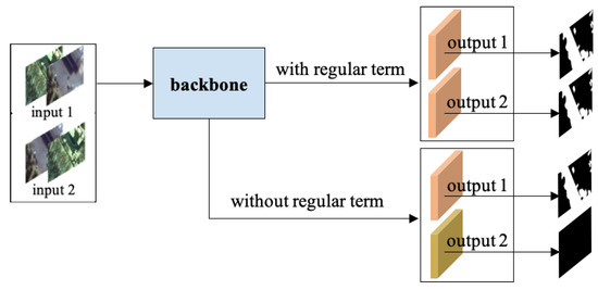
Figure 1.
The principle of the regular term in the objective function.The red blocks are temporal-reliable features. The yellow blocks are not robust features and need to be corrected by the regular term in the objective function.
- (1)
- We first point out a serious problem with the definition of change detection, which exists in early-fusion and late-fusion methods, and propose a novel objective function that brilliantly solves the problem and greatly improves the robustness of these two types of methods;
- (2)
- Due to the importance of spatial information in RSI CD tasks and the defect of partial high-resolution information loss due to the encoder-decoder structure, we design an improved HRNet that solves the difficulty of small target CD to a certain extent;
- (3)
- On two challenging public datasets, we demonstrate the potential of our algorithm through comprehensive experiments and comparisons.
The rest of our work is presented as follows. Section 2 briefly introduces the architecture of HRNet and illustrates the framework of TRCD and a novel objective function for the optimization of the network. Section 3 presents comparative experiments on two public datasets for CD in high-resolution RSI. A discussion of the details and hyper-parameters in the experiment is provided in Section 4. Finally, Section 5 concludes this work and looks to our future work.
2. Methods
2.1. Architectures of HRNet
DCNN has enabled remarkable breakthroughs in various tasks [32,38,48,49]. Most deep neural models map inputs to low-spatial-resolution and high-dimensional representations. The representations are processed differently according to different tasks. For instance, image classification tasks can directly use low-resolution representations for classification, while semantic segmentation tasks need to restore low-resolution representations to high-resolution representations and then classify pixels. For computer vision tasks requiring high-resolution representations, there will inevitably be information loss when encoding inputs and restoring to high-resolution representations. It is hard to achieve higher performance. Recently, HRNet was proposed to solve position-sensitive vision problems in [47]. Unlike traditional convolutional neural networks, HRNet maintains high-resolution features throughout the model. The overall design of HRNet is presented in Figure 2. The resolution of the top branch is the same as the input image. Each time a new branch is added, the spatial resolution representations of the new branch are one-half that of the previous branch, and the number of channels is twice that of the previous branch. Assuming that the input image resolution is 256 × 256, the features of the first, second, third, and last branch contain 48, 96, 192, and 384 channels with 256 × 256, 128 × 128, 64 × 64, and 32 × 32 spatial resolution, respectively. In addition, the feature representations can be exchanged across different resolutions by a tensor fusion module, as depicted in Figure 3. The process of tensor fusion from low resolution to high resolution is illustrated in Figure 3a. The convolution kernel of size 1 × 1 and stride of 1 is applied first on low-resolution representations to ensure that the number of channels is the same as the high-resolution representation. Then, the bilinear interpolation algorithm is adopted for upsampling. The process of tensor fusion from high resolution to low resolution is illustrated in Figure 3c. The convolution kernel of size 3 × 3 and stride of 2 is used once or twice to reduce the spatial resolution. After obtaining the same spatial resolution representations, the features are fused via element-wise summation. The upsampling and downsampling operations in Figure 3b are the same as those in Figure 3a,c. The fundamental processes involved in the network can be seen in Figure 4. The upsampling is implemented by an interpolation algorithm [50], and downsampling is achieved by Convolution 2D [51]. The tensor fusion is illustrated in Figure 4c, where and refer to the value of tensor. When the weights are equal to 1, it means the approach of element-wise summation. In addition, can be a learnable parameter by concatenating two feature tensors and combining a convolution with the size of 1 × 1. More details of the HRNet can be found in [47].
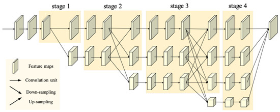
Figure 2.
Illustration of HRNet. This network is composed of four stages.
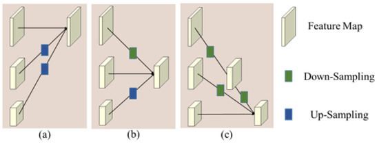
Figure 3.
Tensor fusion module information exchange across different resolutions: (a) illustrates the fusion of high resolution, (b) illustrates the fusion of medium resolution, and (c) illustrates the fusion of low resolution. The downsampling is implemented by 3 × 3 convolution, the stride of which is 2. The upsampling is implemented by bilinear interpolation.

Figure 4.
The fundamental processes involved in the network: (a) diagram of upsampling, (b) diagram of downsampling, and (c) diagram of tensor fusion.
2.2. TRCD
In the next section, we describe our model in detail. Our model aims to determine whether the pixel is changed or unchanged according to the bi-temporal images. We first describe the architecture of TRCD. Subsequently, we present the novel objective function to solve problems affected by the sequence of the raw images in image-fused and feature-fused methods.
2.2.1. Network Architecture
Our framework receives a raw image pair and produces a binary change map, which is an end-to-end architecture. In HRNet, the information interaction between features of different resolutions is only carried out in different stages. In our improved backbone network, features of different resolutions will perform multiple information interactions in the same stage. It is worth emphasizing that our improved network architecture benefits the extraction of semantically richer and more spatially precise information. The network architecture is illustrated in Figure 5. Image t1 and Image t2 are concatenated on the channel dimension as the input with six channels. There are two different sequences for bi-temporal images: input1 and input2. Input1 and input2 will be sent to the network for feature extraction. The extracted features are output1 and output2, correspondingly. If the regular term is not included in the objective function, the extracted features are different in the case where the input is input1 and input2. As depicted in Figure 5, the red and yellow blocks represent different features. The regular term aims to force the model to capture the same features regardless of whether the input is input1 or input2. The two same blocks of red color represent the same features in Figure 5. Only output1 is used to calculate the classification loss, and the distance between output1 and output2 will be calculated as the regularization loss. In order to reduce the missing of small target changes, the highest resolution of features in the backbone network is always maintained at the same resolution as the raw bi-temporal images. There are a total of four stages in the backbone network. The basic block module depicted in Figure 6a is used in the last three stages. The bottleneck module depicted in Figure 6b is used in the first stage. Stage n contains n branches with different spatial resolutions and channel numbers. As the spatial resolution becomes half of the previous one, the number of feature channels is doubled. In our paper, features with the 256 × 256, 128 × 128, 64 × 64, and 32 × 32 spatial resolution have 48, 96, 192, and 384 channels, respectively. The number of exchanges of information across different resolutions in stage 2, stage 3, and stage 4 is set to 1, 4, and 3, respectively. The outputs of stage 4 contain features with different spatial resolutions. The bilinear interpolation algorithm is utilized to improve the resolution of low-resolution representations into high-resolution representations following a convolution unit. A 1 × 1 convolution unit acts on the concatenated features to obtain the probability map. Finally, we get the binary change map by a fixed threshold, which is set to 0.5 in our paper.

Figure 5.
Framework of the proposed TRCD. Input1 and input2 are combinations of bi-temporal images at different sequences. Features of different spatial resolutions will perform multiple information interactions in the same stage. The classification loss is calculated between output1 and the change map. The regularization loss is calculated between output1 and output2.
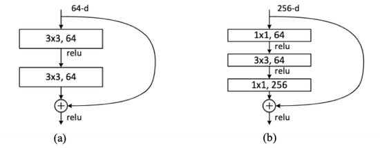
Figure 6.
The residual function in our network: (a) basic block module, (b) bottleneck module.
2.2.2. Objective Function
To a large extent, the essence of deep learning is to utilize the objective function to update and optimize the weight parameters in the network. If the network determines the upper limit of performance, we can state that the objective function is meant to supervise the model so that it can evolve to approach the upper limit. The objective function of a deep neural network usually includes two items: data loss and regular term. The data loss represents the average loss of each sample, which is used to quantify the closeness of prediction and truth. The regular term directly imposes constraints on the parameters to meet certain requirements and is usually used to avoid model overfitting. In our paper, our objective function consists of three parts, namely binary cross entropy (bce) term, dice term, and regular term. The minimization of the objective function under constrained conditions is the loss function. In summary, the objective function is defined as follows:
where the , , and stand for loss of binary cross-entropy, dice, and regularization constraint, respectively; and stand for the height and width of the raw image; and is the value of truth located at of the change map, as seen in Figure 5; a equal to 1 means a changed pixel pair at , while equal to 0 means an unchanged pixel pair at ; stands for the prediction value located at in the probability map under one sequence of bi-temporal images; stands for the prediction value located at in the probability map under another sequence of bi-temporal images; and the hyper parameter aims to balance the loss and regularization constraint. The loss function is defined as follows:
2.2.3. Binary Cross-Entropy Loss
CD in bi-temporal images is essentially a classification task. We aim to perform binary classification on pixels. Therefore, the bce loss is introduced in this work. The formula of bce is as follows:
where stands for the ground truth, and stands for the probability map. The value of is 0 or 1, the value range of is 0–1. is the classification loss with equal to 1, and is the classification loss with equal to 0.
2.2.4. Dice Loss
The unbalanced data issue has always existed in CD tasks. In other word, the changed pixels are far fewer than unchanged pixels. As a result, the model’s predictions are strongly biased toward unchanged pixels, and the recall rate is low because of the missing part of the changes pixels. An objective function designed for medical image segmentation is proposed in [52] to alleviate the issue of category imbalance. The dice coefficient is applied to quantify the similarity of two images. The dice coefficient between two binary images can be formulated as follows:
The value of is between 0 and 1, and we aim to maximize the . The dice loss can be written as follows:
2.2.5. Regular Term
In order to extract similar features under different sequences of bi-temporal images, we design a regular term to restrict the features captured under opposite temporal sequences. The definition of the regularization constraint term is as follows:
As depicted in Formula (6), the regular term uses the norm and aims to force the features under different sequences to be similar. The smaller the regular term, the more similar the extracted features; thereby, the extracted features are temporal reliable. The value range of both and is 0–1.
3. Results
3.1. Datasets
Comprehensive experiments and comparisons were implemented on two public high-resolution image change detection datasets to demonstrate the advance of our proposed model. The first dataset (CDD) was obtained from Google Earth and released in [53] after processing. The original data contains 11 pairs of images (0.03–0.1 m/pixel) from different seasons. Seven pairs of images have a resolution of 4725 × 2700 and are used for manually generating labels. Four pairs of images have a resolution of 1900 × 1000 and are used for manually adding changed objects. The original images are cropped to 256 × 256 pixels and rotated randomly. As depicted in the left of Figure 7, the dataset contains a large number of pseudo-changes caused by seasonal differences and small region changes, such as cars. The publicly released CDD dataset is preprocessed and contains 10,000 pairs of images for training, 3000 pairs of images for validating, and 3000 pairs of images for testing. The CDD dataset can be downloaded at: https://drive.google.com/file/d/1GX656JqqOyBi_Ef0w65kDGVto-nHrNs9 (accessed on 8 May 2022).
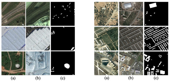
Figure 7.
The left images are selected from the CDD dataset, and the changes are man-made. The right images are selected from the LEVIR-CD dataset, and most changes are caused by the addition of new buildings: (a) prechange, (b) postchange, and (c) ground truth.
The second dataset (LEVIR-CD) was obtained from Google Earth and released in [22]. The dataset has 637 pairs of images with a resolution of 1024 × 1024 pixels (0.5 m/pixel). The changes in the LEVIR-CD dataset include a variety of buildings. As depicted in the right of Figure 7, changes in buildings include villa residences, large warehouses, and so on. It is necessary to emphasize that many changes are caused by the addition of increasing buildings. The dataset is randomly split into three parts: 445 pairs of images for training, 64 pairs of images for validating, and 128 pairs of images for testing. The LEVIR-CD is available for public access at: https://www.google.com/permissions/geoguidelines (accessed on 8 May 2022).
In order to reduce GPU memory usage, we crop the original training sets to a size of 256 × 256 without overleap. For the CDD dataset, we obtain 10,000 pairs of images for training with a size of 256 × 256, 3000 pairs of images for validating, and 3000 pairs of images for testing with a size of 256 × 256. For the LEVIR-CD dataset, we obtain 7120 pairs of images for training with a size of 256 × 256, 1024 pairs of images for validating, and 2048 pairs of images for testing with a size of 256 × 256. The division of the dataset is fixed when the dataset is released to the public. The pretrained weights in [47] are used as the initialization weights of our model. Therefore, our experiments are stable and reproducible.
3.2. Evaluation Metrics
To analyze the validity of our proposed model, four evaluation indexes are introduced: total accuracy (OA), precision (P), recall (R), and F1. Total accuracy is the rate of correctly classified samples compared to all samples and is a frequently used classification metric. However, due to the particularity of change detection, the sample categories are not balanced, so we introduced P, R, and F1. P indicates the rate of true positive (TP) pixels among the positive pixels judged by the classifier. R indicates the rate of positive pixels that have been correctly classified among the total positive pixels. P and R are opposite indicators. The F1 score comprehensively considers P and R. The definitions of the four indexes are as follows:
where denotes the number of true positive pixels, denotes the number of true negative pixels, denotes the number of false positive pixels, and denotes the number of false negative pixels.
3.3. Implements Details
The project code is implemented on the PyTorch framework. Our network and benchmark models are trained using the Adam optimizer. The initial learning rate is set to 1 and multiplied by 0.9 every five epochs. The setting of the learning rate is related to batch size and is dynamically adjusted. The batch size and initial learning rate are scaled in the same proportion in our experiments. Our optimal model is trained on NVIDIA GeForce GTX 3090 × 2 for 100 epochs. The best weights are updated when a higher F1 in the validation dataset is achieved.
3.4. Result Comparison
Our presented algorithm is compared with the other advanced methods on two public datasets. For quantitative assessment, we present the precision, recall, F1, and OA.
3.4.1. On CDD Dataset
The results without L2 regularization in the objective function are shown in Table 1 to analyze the performance of our design framework. Our model gets the best F1 and OA, which can represent the overall performance. The value of precision exceeds all methods except IFN, whose precision is highest but whose recall is relatively low. For comprehensive comparisons, the different prediction change maps and attention maps are displayed in Figure 8. Our algorithm is significantly advanced compared to other SOTA algorithms for change detection of small targets and edges. The explanation for the satisfying detection of object edges and small targets is that our designed framework can extract finer features. The information interaction between features with different spatial resolutions enhances the discriminative ability of features. In addition, to verify the potential of our new objective function, the test dataset is doubled by exchanging the sequence of bi-temporal images. Specifically, the original test dataset contains 3000 pairs of bi-temporal images, and the expanded test set, by exchanging the sequence of bi-temporal images, contains 6000 pairs of images. As shown in Table 2, our proposed objective function has great potential to improve the poor robustness of different temporal sequences among the fusion-based methods. The highest precision, recall, F1, and OA are achieved by our method, and its performance is much better than other methods. The benchmark methods compared are all fusion-based. The temporal relationship between them is not considered during image or feature fusion, resulting in an ideal change map obtained under only one of the temporal sequences. After adding a regular term to the objective function in our method, temporal-reliable features can be obtained. Thus, the bi-temporal images of different sequences can obtain similar feature outputs in our model. For systematic comparisons, the different prediction change maps and attention maps are displayed in Figure 9. An image pair is tested twice, before and after exchanging the bi-temporal sequence. The other fusion-based methods are extremely sensitive to the bi-temporal sequence, while our method is robust. As depicted in Figure 9, our proposed method can obtain similar change maps for the raw bi-temporal images with different sequences. In addition, the attention map indicates that the confidence of the CD results is very high.

Table 1.
Evaluation results of TRCD and other advanced algorithms on CDD with 3000 pairs of images.
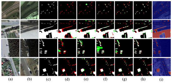
Figure 8.
Qualitative comparison in terms of the detected changes from image t1 to image t2 on the CDD dataset. TP is shown in white, TN is shown in black, FP is shown in green, and FN is shown in red: (a) prechange, (b) postchange, (c) ground truth, (d) FC-siam-conc, (e) UNet++MSOF, (f) IFN, (g) DASNet, (h) our proposed model, and (i) attention map.

Table 2.
Evaluation results of TRCD and other advanced algorithms on CDD with 6000 pairs of images.
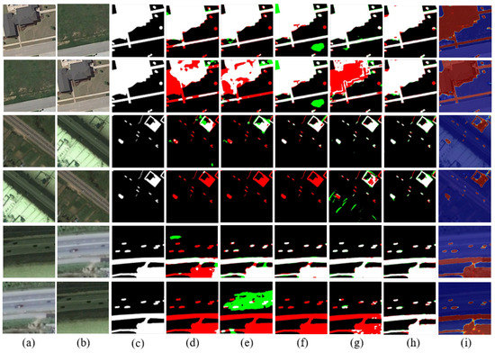
Figure 9.
Qualitative comparison including the detected changes from image t1 to image t2 and changes from image t2 to image t1 on the CDD dataset. The odd and even rows represent the detection results from image t1 to image t2 and results from image t2 to t1, respectively. TP is shown in white, TN is shown in black, FP is shown in green, and FN is shown in red: (a) prechange, (b) postchange, (c) ground truth, (d) FC-siam-diff, (e) UNet++MSOF, (f) IFN, (g) DCFF-Net, (h) our proposed model, and (i) attention map.
Therefore, the method we proposed is effective in solving the problem that exists in fusion-based methods.
3.4.2. On LEVIR-CD Dataset
The performance of our proposed network framework, which is trained without L2 regularization, is shown in Table 3. As depicted, the highest P, F1, and OA are achieved by our proposed method, especially the precision, which is much higher than other advanced algorithms. The visualizations of predicted binary maps are depicted in Figure 10. Similar to the approach to the CDD dataset, we expand the images from 2048 pairs into 4096 pairs by exchanging the bi-temporal sequence. As listed in Table 4, the results on the test set with 4096 pairs of images are displayed to show the potential of our designed objective function. As shown, our model achieves the highest R, F1, and OA. The visualization results of fusion-based methods and our method are depicted in Figure 11. The changes from images t1 to images t2 on LEVIR-CD are mainly increased buildings. Therefore, if we exchange the sequence of the raw images, it is equivalent to letting the model detect the disappearance of buildings. At this time, other fusion-based methods almost fail, while our method displays strong robustness. It is worth emphasizing that the main contributor for obtaining almost the same change map for bi-temporal images of different temporal sequences is the regular term in the objective function, which makes it so that the model will learn the ability to extract temporal-reliable features during the iterative update process. Note that the effect of FC-sima-diff is relatively better than other benchmark methods due to the absolute value of features being stacked in the decoder stage.

Table 3.
Evaluation results of TRCD and other advanced algorithms on LEVIR-CD with 2048 pairs of images.
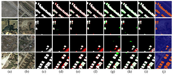
Figure 10.
Qualitative comparison in terms of the detected changes from image t1 to image t2 on the LEVIR-CD dataset. TP is shown in white, TN is shown in black, FP is shown in green, and FN is shown in red: (a) prechange, (b) postchange, (c) ground truth, (d) FC-siam-diff, (e) UNet++MSOF, (f) IFN, (g) DASNet, (h) STANet, (i) our proposed model, and (j) attention map.

Table 4.
Evaluation results of TRCD and other advanced algorithms on LEVIR-CD with 4096 pairs of images.
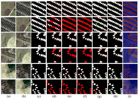
Figure 11.
Qualitative comparison including the detected changes from image t1 to image t2 and changes from image t2 to image t1 on the LEVIR-CD dataset. The odd and even rows represent the detection results from image t1 to image t2 and results from image t2 to t1, respectively. TP is shown in white, TN is shown in black, FP is shown in green, and FN is shown in red: (a) prechange, (b) postchange, (c) ground truth, (d) FC-siam-diff, (e) UNet++MSOF, (f) IFN, (g) DCFF-Net, (h) our prosed model, and (i) attention map.
4. Discussion
4.1. Effect of the Weight
The objective function aims to optimize the weight parameters in our model and is critical in our proposed method. In particular, the weight of the regularization loss and classification loss is balanced by parameter . The value of parameter indicates the strength of forcing the model to extract features that are as similar as possible under the different sequences of prechanged image and postchanged image. The larger the parameter , the closer the features extracted under different sequences of bi-temporal images. As listed in Table 5 and Table 6, a group of including 0.5, 1.0, 1.5, and 2.0 is implemented on the CDD dataset, and the other group of including 1.0, 25.0, 50.0, 75.0, and 100.0 is implemented on the LEVIR-CD dataset. It is necessary to emphasize that the CDD dataset contains both increased and decreased changes, while LEVIR-CD mainly contains increased buildings in terms of the sequence of image t1 to image t2. Therefore, we have two sets of hyper parameters , and the values of the two sets of parameters are quite different. Specifically, the value of parameter on the LEVIR-CD dataset is larger, which represents the model needing to pay more attention to enforce the features extracted under different sequences of similar bi-temporal images.

Table 5.
Quantitative results of the effect of on CDD with 6000 pairs images.

Table 6.
Quantitative results of the effect of on LEVIR-CD with 4096 pairs images.
4.2. Ablation Experiments
In this subsection, ablation experiments are conducted to reveal the effect of our designed objective function and backbone network.
4.2.1. With and without L2
To verify the potential of our designed objective function, we first conduct experiments whose objective function does not contain the regular term on the CDD and LEVIR-CD datasets. The objective function in the second group of experiments contains the regular term. The experiment results shown in Table 7 are obtained with 6000 pairs of test images from the CDD dataset. The quantitative results shown in Table 8 are obtained with 4096 pairs of test images from the LEVIR-CD dataset. The objective function we proposed shows great potential to solve the problem of poor robustness based on fusion-based change detection methods.

Table 7.
Quantitative results of proposed objective function on CDD with 6000 pairs of images.

Table 8.
Quantitative results of proposed objective function on LEVIR-CD with 4096 pairs of images.
4.2.2. Backbone
There are a total of four stages in HRNet, and multi-resolution fusions are conducted between different branches at each stage. The representation ability of features can be enhanced by multi-resolution fusions. Spatial information is relatively rich in high-resolution features, and semantic information is more abundant in low-resolution features.. For the purpose of further enhancing the features interaction between different resolutions, we improved HRNet. Unlike HRNet, which only performs multi-resolution fusion on branches between different stages, TRCD also performs multi-resolution fusion in multiple units of the same stage. It is beneficial to capture the richer semantic features and more precise spatial features. To quantify the improvement of our backbone, we conduct a group of experiments on two public datasets. As shown in Table 9 and Table 10, the improved backbone has increased by 0.34% on the first dataset and increased by 0.26% on the second dataset in terms of F1.

Table 9.
Quantitative results of improved framework on CDD with 3000 pairs of images.

Table 10.
Quantitative results of improved framework on LEVIR-CD with 2048 pairs of images.
5. Conclusions
In this work, we summarize the existing methods and identify the serious limitations in image-fused methods and feature-fused methods. To overcome the poor robustness of different temporal and insufficient spatial information, we propose a temporal-reliable method for CD in RSI. Specifically, we propose a novel objective function to guide the model to learn temporal-reliable features for change detection. Our proposed objective function uses the bi-temporal images before and after exchanging the sequence to share the similar features to realize temporal reliability. Therefore, compared to fusion-based methods, the change maps generated by our method are hardly affected by the sequence of bi-temporal images. Our proposed method solves the robustness problem of fusion-based methods. In addition, we improve the HRNet for change detection to alleviate the challenge that small changes are difficult to detect. The designed framework is experimented on with two public high-resolution image datasets. Both experiment results show its potential and effectiveness for CD.
Future works will focus on fusing global contextual information with the local information extracted by a convolutional neural network.
Author Contributions
Conceptualization, F.P.; methodology, F.P.; formal analysis, F.P.; writing—original draft, F.P.; writing—review and editing, Z.W. (Zebin Wu), X.J., Q.L. and Y.X.; supervision, Z.W. ( Zhihui Wei), Z.W. (Zebin Wu) and Y.X.; funding acquisition, Z.W. (Zebin Wu) and Y.X. All authors have read and agreed to the published version of the manuscript.
Funding
This work was supported in part by the National Natural Science Foundation of China (62071233, 61971223, 61976117), the Jiangsu Provincial Natural Science Foundation of China (BK20211570, BK20180018, BK20191409), the Fundamental Research Funds for the Central Universities (30917015104, 30919011103, 30919011402, 30921011209) , in part by the Key Projects of University Natural Science Fund of Jiangsu Province under Grant 19KJA360001, and in part by the Qinglan Project of Jiangsu Universities under Grant D202062032.
Data Availability Statement
Not applicable.
Conflicts of Interest
The authors declare no conflict of interest. The funders had no role in the design of the study; in the collection, analyses, or interpretation of data; in the writing of the manuscript, or in the decision to publish the results.
References
- Singh, A. Review article digital change detection techniques using remotely-sensed data. Int. J. Remote Sens. 1989, 10, 989–1003. [Google Scholar] [CrossRef] [Green Version]
- Zhu, Z.; Woodcock, C.E. Continuous change detection and classification of land cover using all available Landsat data. Remote Sens. Environ. 2014, 144, 152–171. [Google Scholar] [CrossRef] [Green Version]
- Liu, X.; Lathrop, R., Jr. Urban change detection based on an artificial neural network. Int. J. Remote Sens. 2002, 23, 2513–2518. [Google Scholar] [CrossRef]
- Stramondo, S.; Bignami, C.; Chini, M.; Pierdicca, N.; Tertulliani, A. Satellite radar and optical remote sensing for earthquake damage detection: Results from different case studies. Int. J. Remote Sens. 2006, 27, 4433–4447. [Google Scholar] [CrossRef]
- Coppin, P.; Jonckheere, I.; Nackaerts, K.; Muys, B.; Lambin, E. Review ArticleDigital change detection methods in ecosystem monitoring: A review. Int. J. Remote Sens. 2004, 25, 1565–1596. [Google Scholar] [CrossRef]
- Weismiller, R.; Kristof, S.; Scholz, D.; Anuta, P.; Momin, S. Change detection in coastal zone environments. Photogramm. Eng. Remote Sens. 1977, 43, 1533–1539. [Google Scholar]
- Howarth, P.J.; Wickware, G.M. Procedures for change detection using Landsat digital data. Int. J. Remote Sens. 1981, 2, 277–291. [Google Scholar] [CrossRef]
- Johnson, R.D.; Kasischke, E. Change vector analysis: A technique for the multispectral monitoring of land cover and condition. Int. J. Remote Sens. 1998, 19, 411–426. [Google Scholar] [CrossRef]
- Chen, J.; Gong, P.; He, C.; Pu, R.; Shi, P. Land-use/land-cover change detection using improved change-vector analysis. Photogramm. Eng. Remote Sens. 2003, 69, 369–379. [Google Scholar] [CrossRef] [Green Version]
- Serra, P.; Pons, X.; Sauri, D. Post-classification change detection with data from different sensors: Some accuracy considerations. Int. J. Remote Sens. 2003, 24, 3311–3340. [Google Scholar] [CrossRef]
- Wu, C.; Du, B.; Cui, X.; Zhang, L. A post-classification change detection method based on iterative slow feature analysis and Bayesian soft fusion. Remote Sens. Environ. 2017, 199, 241–255. [Google Scholar] [CrossRef]
- Wan, L.; Xiang, Y.; You, H. A post-classification comparison method for SAR and optical images change detection. IEEE Geosci. Remote Sens. Lett. 2019, 16, 1026–1030. [Google Scholar] [CrossRef]
- Celik, T. Unsupervised change detection in satellite images using principal component analysis and k-means clustering. IEEE Geosci. Remote Sens. Lett. 2009, 6, 772–776. [Google Scholar] [CrossRef]
- Liu, Z.; Li, G.; Mercier, G.; He, Y.; Pan, Q. Change detection in heterogenous remote sensing images via homogeneous pixel transformation. IEEE Trans. Image Process. 2017, 27, 1822–1834. [Google Scholar] [CrossRef]
- Zhang, P.; Gong, M.; Su, L.; Liu, J.; Li, Z. Change detection based on deep feature representation and mapping transformation for multi-spatial-resolution remote sensing images. ISPRS J. Photogramm. Remote Sens. 2016, 116, 24–41. [Google Scholar] [CrossRef]
- Zhang, C.; Yue, P.; Tapete, D.; Jiang, L.; Shangguan, B.; Huang, L.; Liu, G. A deeply supervised image fusion network for change detection in high resolution bi-temporal remote sensing images. ISPRS J. Photogramm. Remote Sens. 2020, 166, 183–200. [Google Scholar] [CrossRef]
- Daudt, R.C.; Le Saux, B.; Boulch, A. Fully convolutional siamese networks for change detection. In Proceedings of the 2018 25th IEEE International Conference on Image Processing (ICIP), Athens, Greece, 7–10 October 2018; pp. 4063–4067. [Google Scholar]
- Peng, D.; Zhang, Y.; Guan, H. End-to-end change detection for high resolution satellite images using improved UNet++. Remote Sens. 2019, 11, 1382. [Google Scholar] [CrossRef] [Green Version]
- Alcantarilla, P.F.; Stent, S.; Ros, G.; Arroyo, R.; Gherardi, R. Street-view change detection with deconvolutional networks. Auton. Robot. 2018, 42, 1301–1322. [Google Scholar] [CrossRef]
- Zhang, X.; Yue, Y.; Gao, W.; Yun, S.; Su, Q.; Yin, H.; Zhang, Y. DifUnet++: A satellite images change detection network based on UNet++ and differential pyramid. IEEE Geosci. Remote Sens. Lett. 2021, 19, 8006605. [Google Scholar] [CrossRef]
- Pan, F.; Wu, Z.; Liu, Q.; Xu, Y.; Wei, Z. DCFF-Net: A Densely Connected Feature Fusion Network for Change Detection in High-Resolution Remote Sensing Images. IEEE J. Sel. Top. Appl. Earth Obs. Remote Sens. 2021, 14, 11974–11985. [Google Scholar] [CrossRef]
- Chen, H.; Shi, Z. A spatial-temporal attention-based method and a new dataset for remote sensing image change detection. Remote Sens. 2020, 12, 1662. [Google Scholar] [CrossRef]
- Fang, S.; Li, K.; Shao, J.; Li, Z. SNUNet-CD: A densely connected siamese network for change detection of VHR images. IEEE Geosci. Remote Sens. Lett. 2021, 19, 8007805. [Google Scholar] [CrossRef]
- Chen, J.; Yuan, Z.; Peng, J.; Chen, L.; Huang, H.; Zhu, J.; Liu, Y.; Li, H. DASNet: Dual attentive fully convolutional siamese networks for change detection in high-resolution satellite images. IEEE J. Sel. Top. Appl. Earth Obs. Remote Sens. 2020, 14, 1194–1206. [Google Scholar] [CrossRef]
- Hou, X.; Bai, Y.; Li, Y.; Shang, C.; Shen, Q. High-resolution triplet network with dynamic multiscale feature for change detection on satellite images. ISPRS J. Photogramm. Remote Sens. 2021, 177, 103–115. [Google Scholar] [CrossRef]
- Liu, J.; Gong, M.; Qin, K.; Zhang, P. A deep convolutional coupling network for change detection based on heterogeneous optical and radar images. IEEE Trans. Neural Netw. Learn. Syst. 2016, 29, 545–559. [Google Scholar] [CrossRef] [PubMed]
- Zhan, Y.; Fu, K.; Yan, M.; Sun, X.; Wang, H.; Qiu, X. Change detection based on deep siamese convolutional network for optical aerial images. IEEE Geosci. Remote Sens. Lett. 2017, 14, 1845–1849. [Google Scholar] [CrossRef]
- Zhang, M.; Xu, G.; Chen, K.; Yan, M.; Sun, X. Triplet-based semantic relation learning for aerial remote sensing image change detection. IEEE Geosci. Remote Sens. Lett. 2018, 16, 266–270. [Google Scholar] [CrossRef]
- Saha, S.; Bovolo, F.; Bruzzone, L. Unsupervised deep change vector analysis for multiple-change detection in VHR images. IEEE Trans. Geosci. Remote Sens. 2019, 57, 3677–3693. [Google Scholar] [CrossRef]
- Du, B.; Ru, L.; Wu, C.; Zhang, L. Unsupervised deep slow feature analysis for change detection in multi-temporal remote sensing images. IEEE Trans. Geosci. Remote Sens. 2019, 57, 9976–9992. [Google Scholar] [CrossRef] [Green Version]
- Wu, C.; Du, B.; Zhang, L. Slow feature analysis for change detection in multispectral imagery. IEEE Trans. Geosci. Remote Sens. 2013, 52, 2858–2874. [Google Scholar] [CrossRef]
- Krizhevsky, A.; Sutskever, I.; Hinton, G.E. Imagenet classification with deep convolutional neural networks. Adv. Neural Inf. Process. Syst. 2012, 25. [Google Scholar] [CrossRef]
- Simonyan, K.; Zisserman, A. Very deep convolutional networks for large-scale image recognition. arXiv 2014, arXiv:1409.1556. [Google Scholar]
- Szegedy, C.; Ioffe, S.; Vanhoucke, V.; Alemi, A.A. Inception-v4, inception-resnet and the impact of residual connections on learning. In Proceedings of the Thirty-First AAAI Conference on Artificial Intelligence, San Francisco, CA, USA, 4–9 February 2017. [Google Scholar]
- Szegedy, C.; Liu, W.; Jia, Y.; Sermanet, P.; Reed, S.; Anguelov, D.; Erhan, D.; Vanhoucke, V.; Rabinovich, A. Going deeper with convolutions. In Proceedings of the IEEE Conference on Computer Vision and Pattern Recognition, Boston, MA, USA, 7–12 June 2015; pp. 1–9. [Google Scholar]
- Szegedy, C.; Vanhoucke, V.; Ioffe, S.; Shlens, J.; Wojna, Z. Rethinking the inception architecture for computer vision. In Proceedings of the IEEE Conference on Computer Vision and Pattern Recognition, Las Vegas, NV, USA, 27–30 June 2016; pp. 2818–2826. [Google Scholar]
- He, K.; Zhang, X.; Ren, S.; Sun, J. Deep residual learning for image recognition. In Proceedings of the IEEE Conference on Computer Vision and Pattern Recognition, Las Vegas, NV, USA, 27–30 June 2016; pp. 770–778. [Google Scholar]
- Long, J.; Shelhamer, E.; Darrell, T. Fully convolutional networks for semantic segmentation. In Proceedings of the IEEE Conference on Computer Vision and Pattern Recognition, Boston, MA, USA, 7–12 June 2015; pp. 3431–3440. [Google Scholar]
- Ronneberger, O.; Fischer, P.; Brox, T. U-net: Convolutional networks for biomedical image segmentation. In Proceedings of the International Conference on Medical Image Computing and Computer-Assisted Intervention; Springer: Berlin/Heidelberg, Germany, 2015; pp. 234–241. [Google Scholar]
- Zhou, Z.; Rahman Siddiquee, M.M.; Tajbakhsh, N.; Liang, J. Unet++: A nested u-net architecture for medical image segmentation. In Deep Learning in Medical Image Analysis and Multimodal Learning for Clinical Decision Support; Springer: Berlin/Heidelberg, Germany, 2018; pp. 3–11. [Google Scholar]
- Hadsell, R.; Chopra, S.; LeCun, Y. Dimensionality reduction by learning an invariant mapping. In Proceedings of the 2006 IEEE Computer Society Conference on Computer Vision and Pattern Recognition (CVPR’06), New York, NY, USA, 17–22 June 2006; Volume 2, pp. 1735–1742. [Google Scholar]
- Fu, J.; Liu, J.; Tian, H.; Li, Y.; Bao, Y.; Fang, Z.; Lu, H. Dual attention network for scene segmentation. In Proceedings of the Proceedings of the IEEE/CVF Conference on Computer Vision and Pattern Recognition, Long Beach, CA, USA, 15–20 June 2019; pp. 3146–3154.
- Badrinarayanan, V.; Kendall, A.; SegNet, R.C. A deep convolutional encoder-decoder architecture for image segmentation. arXiv 2015, arXiv:1511.00561. [Google Scholar] [CrossRef] [PubMed]
- Du, H.; Duan, Z. Finder: A novel approach of change point detection for multivariate time series. Appl. Intell. 2022, 52, 2496–2509. [Google Scholar] [CrossRef]
- Faber, K.; Corizzo, R.; Sniezynski, B.; Baron, M.; Japkowicz, N. WATCH: Wasserstein Change Point Detection for High-Dimensional Time Series Data. In Proceedings of the 2021 IEEE International Conference on Big Data (Big Data), Orlando, FL, USA, 15–18 December 2021; pp. 4450–4459. [Google Scholar]
- Cheng, G.; Zhou, P.; Han, J. Learning rotation-invariant convolutional neural networks for object detection in VHR optical remote sensing images. IEEE Trans. Geosci. Remote Sens. 2016, 54, 7405–7415. [Google Scholar] [CrossRef]
- Wang, J.; Sun, K.; Cheng, T.; Jiang, B.; Deng, C.; Zhao, Y.; Liu, D.; Mu, Y.; Tan, M.; Wang, X.; et al. Deep high-resolution representation learning for visual recognition. IEEE Trans. Pattern Anal. Mach. Intell. 2020, 43, 3349–3364. [Google Scholar] [CrossRef] [Green Version]
- Ren, S.; He, K.; Girshick, R.; Sun, J. Faster r-cnn: Towards real-time object detection with region proposal networks. IEEE Trans. Pattern Anal. Mach. Intell. 2017, 39, 1137–1149. [Google Scholar] [CrossRef] [Green Version]
- Sun, K.; Xiao, B.; Liu, D.; Wang, J. Deep high-resolution representation learning for human pose estimation. In Proceedings of the Proceedings of the IEEE/CVF Conference on Computer Vision and Pattern Recognition, Long Beach, CA, USA, 15–20 June 2019; pp. 5693–5703.
- Kolarik, M.; Burget, R.; Riha, K. Upsampling algorithms for autoencoder segmentation neural networks: A comparison study. In Proceedings of the 2019 11th International Congress on Ultra Modern Telecommunications and Control Systems and Workshops (ICUMT), Dublin, Ireland, 28–30 October 2019; pp. 1–5. [Google Scholar]
- Dumoulin, V.; Visin, F. A guide to convolution arithmetic for deep learning. arXiv 2016, arXiv:1603.07285. [Google Scholar]
- Milletari, F.; Navab, N.; Ahmadi, S.A. V-net: Fully convolutional neural networks for volumetric medical image segmentation. In Proceedings of the 2016 Fourth International Conference on 3D Vision (3DV), Stanford, CA, USA, 25–28 October 2016; pp. 565–571. [Google Scholar]
- Lebedev, M.; Vizilter, Y.V.; Vygolov, O.; Knyaz, V.; Rubis, A.Y. Change detection in remote sensing images using conditional adversarial networks. Int. Arch. Photogramm. Remote Sens. Spat. Inf. Sci. 2018, 42, 565–571. [Google Scholar] [CrossRef] [Green Version]
Publisher’s Note: MDPI stays neutral with regard to jurisdictional claims in published maps and institutional affiliations. |
© 2022 by the authors. Licensee MDPI, Basel, Switzerland. This article is an open access article distributed under the terms and conditions of the Creative Commons Attribution (CC BY) license (https://creativecommons.org/licenses/by/4.0/).