Abstract
Airborne synthetic aperture radar (Airborne SAR) can accurately locate key targets and regions by using the flight parameters of the aircraft and the relative position information between the aircraft and the target which can be obtained from the airborne positioning and orientation system (POS). In the course of flight, the aircraft will deviate from the ideal flight path due to atmospheric turbulence, which results in the calculation deviating from the actual target position. In order to improve the target positioning accuracy, it is necessary to study the influence of aircraft motion error on the target positioning error. This study discusses the positioning accuracy of single-view airborne SAR from the perspective of linear Range-Doppler algorithm (RDA), and deduces the multi-view airborne SAR positioning error transfer model based on the multi-view airborne SAR positioning model. Based on these, we analyze the main factors that affect the positioning accuracy of the two positioning methods in detail and quantitatively reveal the mechanism by which the multi-view airborne SAR positioning method can improve the target positioning accuracy compared with the single-view airborne SAR positioning method; we also solve the problem of course planning for multi-view airborne SAR optimal positioning. The research results can provide theoretical support for the analysis of factors influencing positioning error and the positioning error correction of airborne SAR.
1. Introduction
Synthetic aperture radar (SAR) has the advantages of all-sky and all-weather imaging, and is an important tool for high-resolution earth observation [1,2,3]. Accurate target location is one of the important uses of SAR [4,5], and SAR image positioning is an effective means to obtain three-dimensional position information of the target, which has important application value in digital elevation model (DEM) generation of imaging area, topographic map drawing and accurate interpretation of military targets. Traditional SAR image positioning methods mainly include the polynomial model, collinearity equation model [6,7] and Range-Doppler model [8,9,10]. Because the polynomial model and collinearity equation model do not conform to the SAR side view imaging principle, have no clear geometric and physical significance and must rely on ground control points to invert model parameters to complete SAR image positioning, they cannot be used for automatic real-time SAR image positioning. The Range-Doppler model, based on the two characteristics of SAR side view oblique imaging and Doppler frequency shift, uses the range equation and Doppler frequency equation to establish the functional relationship between the image point coordinates of SAR oblique image and radar platform coordinates, which has clear geometric and physical significance and has been widely used in SAR image stereoscopic positioning. For airborne SAR image positioning, according to the number of flight passes and SAR images which are needed to complete image positioning, airborne SAR image positioning can be divided into single-view and multi-view airborne SAR image positioning [11]. In the field of remote sensing, a large number of studies have been carried out on single-view airborne SAR image positioning, and these studies are generally based on the Range-Doppler model [12,13,14,15] or the extended Range-Doppler model [16,17,18,19,20,21] to complete SAR image positioning. For the positioning of a multi-view airborne SAR image, the stereoscopic positioning of the same target, which is in two or more SAR images which have a good intersection effect, is usually solved by Range-Doppler equations [22,23,24,25,26].
An airborne SAR platform is easily affected by inertial navigation drift, wind speed, wind direction and air flow during theaircraft’s flight. These factors prevent the aircraft flying in a precisely uniform motion in a straight line. The position error and velocity error of the aircraft are large, leading to deviation in the parameters for calculation of the positioning model, which eventually will seriously affect the positioning accuracy of the target. Therefore, it is necessary to analyze the factors affecting the positioning accuracy of airborne SAR, which can provide theoretical support for the positioning accuracy index design of airborne SAR systems. On the one hand, most of the researches on the factors affecting the positioning error of single-view airborne SAR are based on using the geometric relationship of imaging to analyze SAR positioning accuracy, and the analytical formula of the positioning error is given. The authors also point out that aircraft velocity error in range is the main factor affecting the positioning accuracy, but the analysis of the inertial navigation parameters of aircraft is lacking [27,28,29]. On the other hand, relatively few studies have been carried out to analyze the influencing factors of multi-view airborne SAR positioning error, and the related research works need to be further improved. Intuitively, compared with the single-view airborne SAR positioning method, the multi-view airborne SAR positioning method using at least two SAR images will add more target information and enhance the anti-jamming performance of the positioning process, making the multi-view airborne SAR positioning method more accurate. This is the reason why the multi-view airborne SAR positioning method is more and more widely used in the field of SAR image positioning. However, there is little theoretical proof that the multi-view airborne SAR positioning method is better than the single-view airborne SAR positioning method in the field of airborne SAR positioning.
This paper is devoted to perfecting research into airborne SAR positioning error analysis. We derive the analytical expression of single-view airborne SAR positioning error from the point of view of linear RDA, and we also derive the multi-view airborne SAR positioning error transfer model from the perspective of the multi-view airborne SAR positioning model. Based on these, the positioning error analysis of single-view and multi-view airborne SAR can be put into the same frame. The main influencing factors of airborne SAR positioning error are discussed and the advantages of multi-view airborne SAR positioning method are proved theoretically. We also study the course planning of aircraft for multi-view airborne SAR optimal positioning and find some useful rules.
The remainder of this paper is organized as follows: Section 2 gives the transfer models of the single-view and the multi-view airborne SAR positioning error and gives an effective method to analyze the influence of dual aircraft geometry configuration on target positioning accuracy. Section 3 verifies the effectiveness of the proposed multi-view airborne SAR positioning error transfer model by aircraft flight experiments, performs a comparative analysis on the factors influencing single-view and multi-view airborne SAR positioning error, and tests the influence of the course relationship between dual aircraft on the multi-view airborne SAR positioning accuracy. A discussion is offered in Section 4. Finally, the conclusions of this study are drawn in Section 5.
2. Methodology
2.1. Analytical Expression of Single-View Airborne SAR Positioning Error
When the classical linear Range-Doppler Algorithm (RDA) processes single-view airborne SAR data, it firstly uses the parameters provided by the inertial navigation system (INS) to generate a reference signal which is used to compensate the radar echo signal. It then obtains high-resolution SAR image through the two-dimensional Fourier transform, and finally performs geometric distortion correction on the image with the scene center as the reference point [30]. The center of the scene can be fully focused after the RDA processing. Without considering the influence of terrain fluctuation, we can deduce the influence of aircraft position errors (dxs,dys,dzs) and velocity errors (dvx,dvy,dvz) on target positioning accuracy from the perspective of the RDA. The analytical expression of single-view airborne SAR positioning error can be summarized as shown in Table 1. The detailed derivation of Table 1 is given in Appendix A.

Table 1.
Analytical expression of single-view airborne SAR positioning error.
2.2. Multi-View Airborne SAR Positioning and Course Planning Analysis Method
2.2.1. Multi-View Airborne SAR Positioning Model
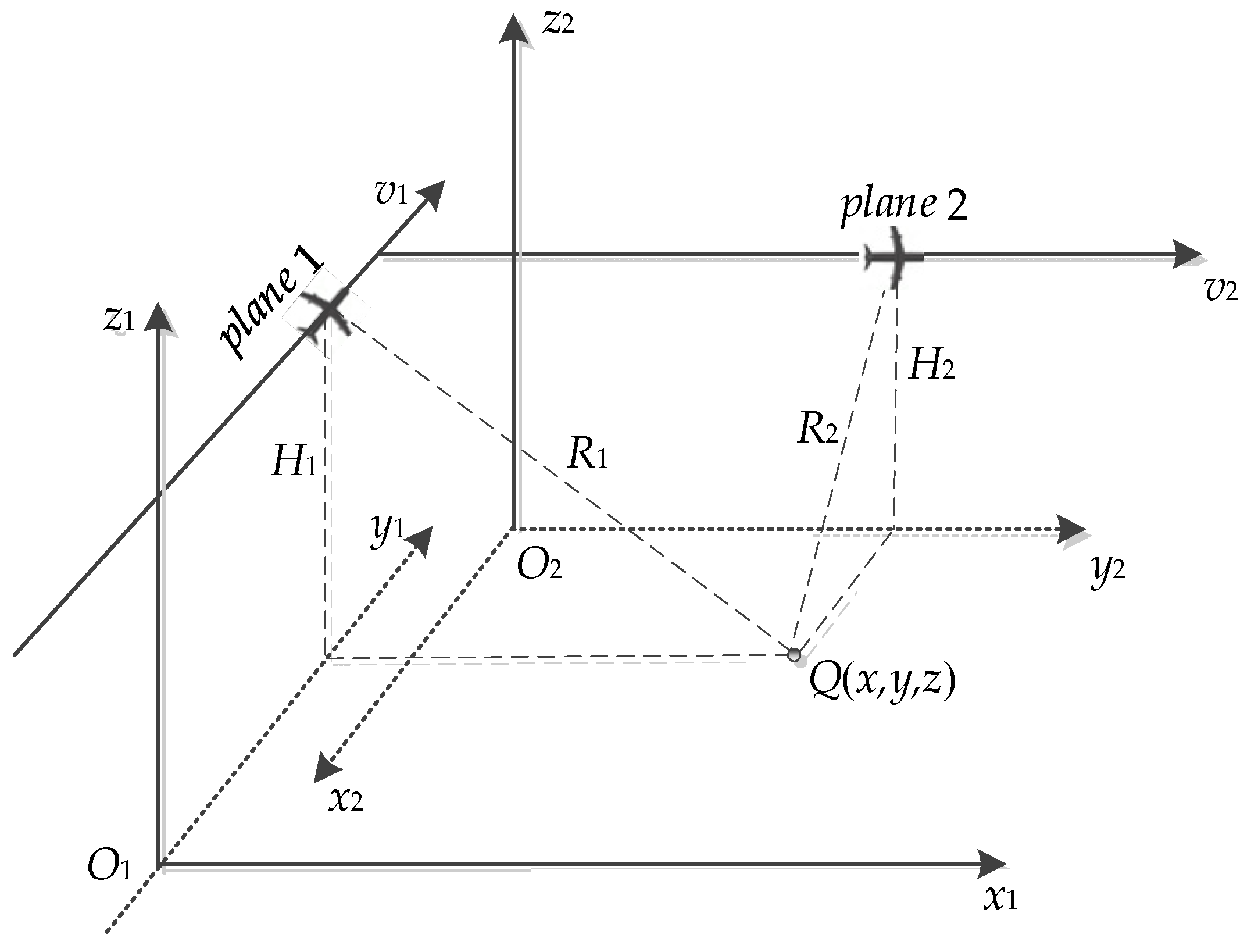
As shown in Figure 1, it is assumed that airborne SAR conducts strip model imaging of the same target area from two intersecting routes; the O1-x1y1z1 and O2-x2y2z2 are, respectively, the imaging coordinate systems where the two aircraft are located.
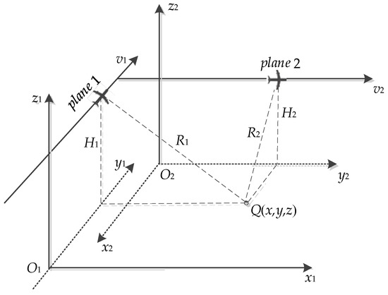
Figure 1.
Geometric relationships in multi-view airborne SAR.
The position of the target can be determined by the position and velocity of the radar antenna phase center and the slant distance between target and antenna. The relatively strict distance condition and Doppler frequency condition (1) are satisfied between target Q and the radar antenna phase center on the routes under Earth Center Fixed (ECF) coordinate system. Solving the Equation (1) can realize target location.
where Fi (i = 1,…,4) are multi-variate functions, (X,Y,Z) is the position of the target, (XS1,YS1,ZS1) and (VX1,VY1,VZ1) are, respectively, the position and velocity of the radar antenna 1 phase center, (XS2,YS2,ZS2) and (VX2,VY2,VZ2) are respectively the position and velocity of the radar antenna 2 phase center under ECF coordinate system, R1 and R2 are the oblique distance between the radar antenna phase center of dual aircraft and target respectively, fdc1 and fdc2 are radar antenna Doppler center frequency of dual aircraft, respectively. The latitude, longitude, altitude and velocity of the radar antenna can be obtained by the airborne GPS and INS and can be converted to ECF coordinate system. The slant distance between the radar antenna and the target can be determined by the radar short-range delay, range resolution and the pixel coordinates of the target which is in the SAR image.
Equation (1) is a nonlinear system about the target position, which needs to be solved by using the linearized Newton iteration method [16], so as to obtain the three-dimensional position of the target.
2.2.2. Multi-View Airborne SAR Positioning Error Transfer Model
The aircraft will deviate from the ideal route due to random jitter which is caused by atmospheric turbulence and other influences during flight. This random motion error can lead to a deviation between the actual position and velocity of the aircraft measured by POS and the aircrafts’ ideal position and velocity, and this error will cause the target pixel in SAR image to be biased, which will eventually lead to inaccurate target positioning. Therefore, it is necessary to study the influence of dual aircraft position error and velocity error on target location error.
The first order differential of dual aircraft position and velocity by using Equation (1) can be expressed as:
We define the positioning error estimation of the multi-view airborne SAR on the target as:
When the position errors and velocity errors of dual aircraft exist, we can independently analyze the influence of dual aircraft position errors and velocity errors on target positioning error in multi-view airborne SAR positioning model by using the above positioning error transfer model.
2.2.3. Course Planning Analysis Method for Multi-View Airborne SAR Platform
It is assumed that dual aircraft motion error is consistent during flight. Compared with target localization using single-view airborne SAR, the positioning accuracy of multi-view airborne SAR on target may be related to the platform geometric position, which includes dual aircraft course Angle φ and the Angle of view θ under radar antenna during the flight. We study the analysis method of the influence of dual aircraft geometry configuration (φ and θ) on target positioning error when there are motion errors in this section.
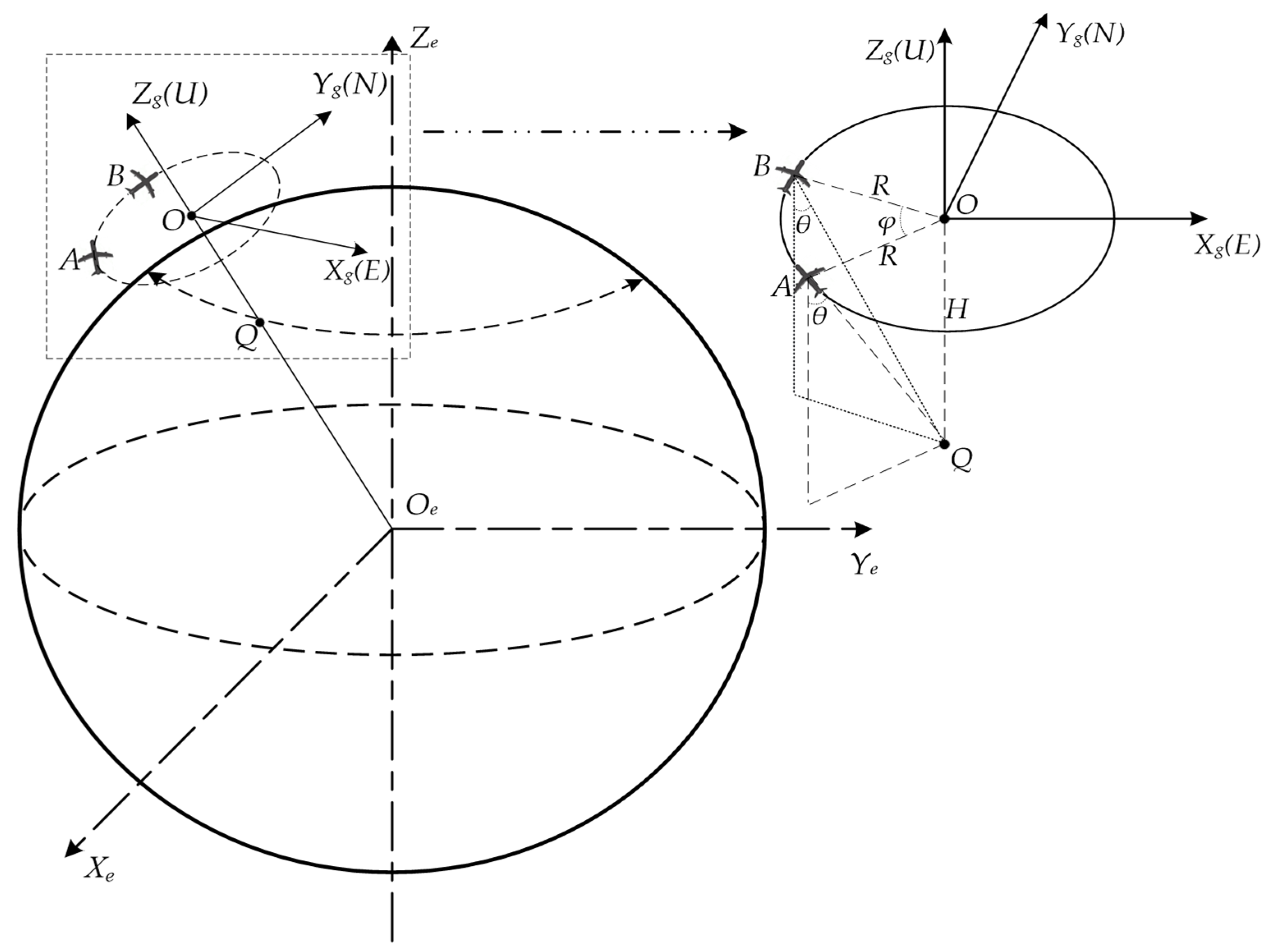
Figure 2 is the geometric configuration diagram of the two platforms, where Oe-XeYeZe is the ECF coordinate system, O-XgYgZg is the east, north and up (ENU) coordinate system. Point Q is the target, point A and B are the positions of the two antennas phase center corresponding to the target, and the point O whose height is H is above the target Q. Suppose that two platforms are flying at an altitude of H, the Angle of view under the two radar antennas to the target Q is θ, and the course Angle of dual aircraft is φ.
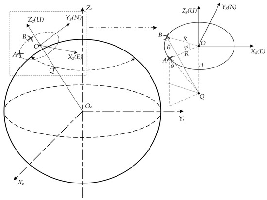
Figure 2.
Dual aircraft geometric configuration.
In the process of radar platform positioning of the target, the positions of the origin O and the antenna phase center A, B in the ENU coordinate system O-XgYgZg are O(0,0,0), A(x,y,0) and B(x1,y1,0), respectively. It can be obtained from the geometric relationship between the phase center of the antenna and the target that:
Under the conditions of knowing A(x,y,0), the course Angle φ and the Angle of view θ under the antenna, we can figure out the position B(x1,y1,0). Then, the positions of point A(XS1,YS1,ZS1) and point B(XS2,YS2,ZS2) in the ECF coordinate system can be obtained according to the transformation relation between the target position in the ENU coordinate system and that in the ECF coordinate system [23].
By introducing the positions A(XS1,YS1,ZS1) and B(XS2,YS2,ZS2) into the multi-view airborne SAR positioning error transfer model, the influence of dual aircraft geometric configuration (φ and θ) on the target positioning accuracy can be analyzed.
3. Experiment Results and Analysis
In this part, we first verify the effectiveness of the multi-view airborne SAR positioning error transfer model by multi-view airborne SAR simulation positioning experiment. Then, we use the single-view and multi-view airborne SAR positioning error transfer models which are established above to analyze the positioning error of the single-view and multi-view airborne SAR in a unified framework, and discuss the advantages and disadvantages of the two positioning models as well as the main influencing factors of the two models on the target positioning error. Finally, aiming at the optimal location problem of the multi-view airborne SAR, we analyze the specific influence of the dual aircraft geometry configuration on the target positioning accuracy.
3.1. Accuracy Verification of Multi-View Airborne SAR Positioning Error Transfer Model
3.1.1. Verification Experiment Design
We assume that the real position of the target is (X0,Y0,Z0) and the target position solved by using multi-view airborne SAR positioning model (1) is (X,Y,Z) when the dual aircraft have motion error. In the traditional multi-view airborne SAR positioning field, we regard d as the actual target positioning error caused by the motion error of the dual aircraft, and the d is:
Above, we propose that the multi-view airborne SAR positioning error transfer model (3) can be used to estimate the actual target positioning error d caused by the aircraft motion error, but whether the estimate d1 of the actual target positioning error d is effective needs further verification.
We carry out the following two simulation experiments to verify the effectiveness of the multi-view airborne SAR positioning error transfer model:
- Simulated flight experiment: Add single motion error (position or velocity) to the aircraft in the imaging coordinate system, and then obtain the position and velocity of the radar antenna phase center through the simulation experiment, and complete the error locating of the target according to Equation (1). Based on the known real position of the target, we can obtain the actual target positioning error d caused by the aircraft motion error according to Equation (5).
- Positioning error transfer experiment: Under the premise of knowing the target real position and the radar antenna phase center real position, real velocity, we can convert the motion error which is added to the aircraft in the imaging coordinate system in experiment a. into the aircraft motion error which is under ECF coordinate system according to Appendix C and then put it into error transfer model. Finally, the target positioning error estimation d1 is calculated according to Equation (3).
Comparing d and d1 can verify the validity of the multi-view airborne SAR positioning error transfer model.
3.1.2. Experimental Parameter Setting and Verification Results
Set dual aircraft system parameters to be consistent in experiment a., as shown in Table 2. Aircraft 1 is flying due north and aircraft 2 is flying due east. The real positions of the target and the radar antenna phase center are shown in Table 3.
Table 2.
System Parameters.
Table 3.
Real positions of the target and antenna.
In the imaging coordinate system, position errors of 3 m in the range (Case1), azimuth (Case2), altitude (Case3) and velocity errors of 0.3 m/s in the range (Case4), azimuth (Case5), altitude (Case6) and the combined error of these six motion errors (Case7) are separately added to dual aircraft in turn. The error locating result and actual positioning error d of the multi-view airborne SAR positioning model (1) on the target in experiment a. and the target positioning error estimation d1 which is calculated by the error transfer model in experiment b. are shown in Table 4.
Table 4.
Positioning Results and Location Errors of the target.
It can be seen from Table 4 that, under the influence of seven error sources, the actual target positioning error d through the simulation flight experiment is basically consistent with the target positioning error estimation d1 which is calculated through the error transfer model, and the root mean square error of d and d1 is 0.07 m, showing that the positioning error analysis accuracy of the multi-view airborne SAR positioning error transfer model on target can reach a high level. Compared with using signal simulation experiments which need the iterative solution of the positioning system (1) to analyze the positioning error, the error transfer model is simple and efficient, and it is an useful tool for analyzing the influence of multi-view airborne SAR platform motion error on the target positioning accuracy.
3.2. Comparative Analysis of Single-View and Multi-View Airborne SAR Positioning Error
Aircraft motion error can be decomposed into the range, azimuth and altitude position error and velocity error during flight. For multi-view airborne SAR positioning method, the motion error (D1,D2) of dual aircraft in any direction can be decomposed into the combination of Common Mode (CM) motion errors (m,m) and Differential Mode (DM) motion errors (n,−n), where:
and:
We can regard the motion error which is generated by the dual aircraft under the same external conditions as the CM motion error, and regard the motion error generated by the opposite external conditions as the DM motion error. We can also define aircraft motion error which is in the direction of range to the right, azimuth to the forward and altitude to the upward as positive.
The dual aircraft system parameters, target position and the two antennas phase center positions are set as described in Section 3.1.2; the ranges of the dual aircraft position error and velocity error in range, azimuth and altitude are [–5, 5] m and [−0.5, 0.5] m/s respectively. Based on the analysis of the single-view and multi-view airborne SAR location error transfer models, the influences of single aircraft motion error, the CM and DM motion error of the dual aircraft on target positioning accuracy are shown in Figure 3.
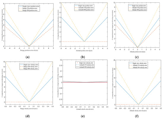
Figure 3.
Influence curve of single-view and multi-view airborne SAR motion error on target positioning error. (a–c) Influence of aircraft position error in range, azimuth and altitude on target positioning error. (d–f) Influence of aircraft velocity error in range, azimuth and altitude on target positioning error.
Figure 3 reveals the general rule of influence which is about aircraft motion error on target positioning accuracy in two positioning modes. Comprehensive analysis of Figure 3 can draw the following conclusions:
- (1)
- The velocity errors of aircraft in range and altitude are the main factors affecting the single-view airborne SAR positioning accuracy.
- (2)
- Dual aircraft DM velocity errors in range and altitude are the main factors affecting the positioning accuracy of the multi-view airborne SAR.
- (3)
- Dual aircraft CM position error in azimuth and CM velocity errors in range, azimuth and altitude basically do not affect the positioning accuracy of the multi-view airborne SAR.
- (4)
- Comparing (a–f) we can see that compared to the effect of single-view airborne SAR motion error on the target positioning error, the influence of aircraft motion error on the target positioning error will be suppressed when dual aircraft motion errors constitute CM motion errors, while the influence of aircraft motion error on the target positioning error will be amplified when dual aircraft motion errors constitute DM motion errors. This rule reveals the advantage of the multi-view airborne SAR positioning method compared with the single-view airborne SAR positioning method. Thus, dual aircraft of the same type are used to complete the positioning of the target in the same environment as far as possible. In this case, dual aircraft motion errors can be basically regarded as CM motion errors which will make the positioning accuracy of multi-view airborne SAR higher than that of single-view airborne SAR. If the working environment of dual aircraft is very different, dual aircraft DM motion errors are the main motion errors, which will lead to the target positioning effect of multi-view airborne SAR being inferior to that of single-view airborne SAR.
3.3. Course Planning for Multi-View Airborne SAR Optimal Positioning
3.3.1. Course Angle Optimization of Dual Aircraft
Set the system parameters of the dual aircraft to be consistent, as shown in Table 2. Aircraft A is flying due north and the course Angle between aircraft A and aircraft B is φ. The real positions of the target and the radar antenna 1 phase center are shown in Table 3.
According to Equation (4), the position of aircraft B in ENU coordinate system is:
Then, the position of aircraft B synthetic aperture center corresponding to the target under ECF coordinate system can be obtained. It is assumed that the motion errors of the dual aircraft are consistent during flight: in the imaging coordinate system, position errors of 3 m in the range (dxs), azimuth (dys), altitude (dzs) and velocity errors of 0.3 m/s in the range (dvx), azimuth (dvy), altitude (dvz) and the combined motion error (CME) of these six motion errors are separately added to the dual aircraft in turn. We use the multi-view airborne SAR positioning error transfer model to analyze the influence of dual aircraft course Angle φ on target positioning error, and the analysis results are shown in Figure 4.
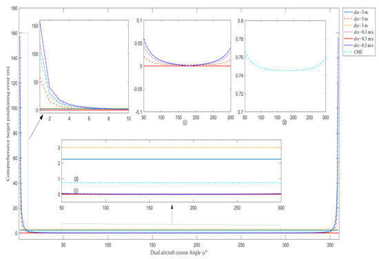
Figure 4.
Influence curve of dual aircraft course Angle φ on target positioning error.
As can be seen from Figure 4, for the single motion error of dual aircraft, the target positioning errors caused by dual aircraft velocity errors in range, altitude and position error in azimuth are sensitive to the smaller or the larger dual aircraft course Angle φ; the target positioning errors caused by dual aircraft position errors in range, altitude and velocity error in azimuth are basically not affected by dual aircraft course Angle φ. When dual aircraft course Angle φ is too large or too small, the multi-view airborne SAR positioning method will cause excessive target positioning error. However, the target positioning error is relatively small and the floating range is within 1 m when dual aircraft course Angle φ is between [10°, 350°]. In particular, the target positioning error is minimum when dual aircraft course Angle φ is near 180°. Therefore, when we use the multi-view airborne SAR positioning method to complete target positioning, in order to make the target positioning error caused by dual aircraft motion error relatively small, the dual aircraft course Angle φ should not be too small or too large, preferably around 180°.
3.3.2. View Angle Optimization under Radar Antenna
When analyzing the influence of the Angle of view θ under antenna on target positioning accuracy, in order to simplify the discussion, dual aircraft are set to fly vertically, and dual aircraft synthetic aperture centers corresponding to the target are located due north and due west of the target, respectively. The system parameters of the dual aircraft except pitch angle are shown in Table 2 and the real position of the target is shown in Table 3.
The positions of dual aircraft in ENU coordinate system O-XgYgZg are A(−x,0,0) and B(0,x,0), respectively. According to Equation (4), we can obtain that x = H·tan(θ). Similar to the above analysis which is about the influence of dual aircraft course Angle φ on target positioning error, seven types of motion error are successively added to the aircraft. Using the multi-view airborne SAR positioning error transfer model to analyze the influence of the Angle of view θ under antenna on target positioning error and the analysis gives the results shown in Figure 5.
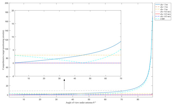
Figure 5.
Influence curve of the Angle of view θ under antenna on target positioning error.
As can be seen from Figure 5, for the single motion error of dual aircraft, the floating range of the target positioning error caused by dual aircraft motion error is small when Angle of view θ under antenna is small, and the target positioning error caused by dual aircraft position error in range is sensitive to the larger Angle of view θ under antenna; the target positioning errors caused by dual aircraft position error in azimuth, altitude and velocity errors are not affected by the Angle of view θ under antenna. More importantly, with the increase of θ, the target positioning error caused by CME decreases first and then increases, when the Angle of view θ under antenna is within the range of [30°, 60°], the target positioning error caused by dual aircraft motion error is relatively small and the floating rang is within 1 m.
4. Discussion
The aircraft will deviate from the ideal flight path under the influence of some factors which include the measurable wind direction and wind speed. We can measure the wind direction and wind speed in the expected flight area of the aircraft in advance, and decompose the wind speed into the imaging coordinate system where the aircraft is located according to the geometric composition relationship between the planned flight track of the aircraft and the wind direction in the flight area. The positioning accuracy of the airborne SAR can be improved by using the proposed positioning error analysis method to quantitatively calculate the specific influence of wind direction and speed on the positioning process and then compensate the influence in the positioning results. We can also make use of the conclusions reached in Section 3.2 to adjust the course of the aircraft in time according to the wind direction in the observation area, so that the motion errors of the aircraft caused by wind direction and wind speed are not in range direction and altitude direction in the single-view positioning mode, trying to form the CM relationship in the multi-view positioning model.
In order to achieve the optimal positioning of the multi-view airborne SAR, the course Angle between the dual aircraft should be about 180° and the Angle of view under antenna should not be too large, which is in accordance with common sense. The course Angle between the dual aircraft is 180° means that the overlap degree of the same target area observed by the dual aircraft is the highest, providing more target information, so the positioning effect is the best. If the Angle of view under antenna is too large, this means that the observation distance of the radar is long. In this case, the small motion error of the aircraft will lead to a large positioning error. These rules have important reference value for optimizing the positioning effect of airborne SAR.
5. Conclusions
There is a lack of an effective and unified tool to analyze the single-view and multi-view airborne SAR positioning error. In light of the deficiency of airborne SAR positioning error analysis, this paper deduces the specific influence modes of aircraft motion error on target positioning error under different positioning modes based on the linear RDA and multi-view airborne SAR positioning models, respectively. Based on these, the results of comparative analysis of single-view and multi-view airborne SAR positioning error show that velocity errors in range and altitude are the main factors affecting the single-view airborne SAR positioning accuracy. Dual aircraft DM motion errors are the main reason for the inaccurate positioning of multi-view airborne SAR; and dual aircraft CM motion errors can restrain the influence of aircraft motion error on target positioning accuracy. Thus, the multi-view airborne SAR positioning method can achieve higher target positioning accuracy compared with the single-view airborne SAR positioning method when dual aircraft are working in the same environment. In order to optimize the positioning effect of the multi-view airborne SAR positioning method, the course Angle φ between the dual aircraft should be around 180°, and the Angle of view θ under antenna should be within the range of [30°,60°]. These rules have a good guiding effect on the aircraft motion attitude when we want to achieve high precision target positioning by airborne SAR. Further research is needed to verify the judgment about the influence of the aircraft motion error on the target positioning error through the aircraft positioning experiment.
Author Contributions
All the authors made significant contributions to the work. B.Z. and A.Y. carried out the theoretical framework. B.Z., A.Y., X.C. and Z.W. conceived and designed the experiments; B.Z. performed the experiments and wrote the manuscript; B.Z. and A.Y. analyzed the data; Z.D. gave insightful suggestions for the work and the manuscript. All authors have read and agreed to the published version of the manuscript.
Funding
This research was funded partly by the National Natural Science Foundation of China (NSFC) under Grant NO. 62101568, and partly by the Scientific Research Program of the National University of Defense Technology (NUDT) under Grant ZK21-06.
Data Availability Statement
The data presented in this study are available on request from the corresponding author.
Acknowledgments
The authors would like to thank all the anonymous reviewers for their valuable comments and helpful suggestions which lead to substantial improvements of this paper.
Conflicts of Interest
The authors declare no conflict of interest.
Appendix A
This Appendix is used to explain how to use the RDA to derive the analytical expression of the single-view airborne SAR positioning error. Assume that the aircraft flies from A to B at velocity va, and point C(X0,Y0,Z0) is the center of the synthetic aperture. We take the ground projection of the point C as the origin O to establish the geometric coordinate system of imaging as shown in Figure A1. θ is the Angle of view under antenna phase center at the center of the synthetic aperture, h is the flight altitude of the aircraft, point D(x1,y1,0) is the center of the imaging scene, p(x,y,0) is any point in the imaging scene.
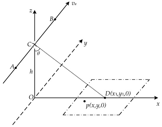
Figure A1.
Geometric relationship of single-view airborne SAR imaging.
Figure A1.
Geometric relationship of single-view airborne SAR imaging.

The coordinates of point D which is in the center of the scene can be expressed as:
The coordinates of the synthetic aperture center C are:
The ideal flight path of the aircraft can be expressed as:
The instantaneous distance between the phase center of radar antenna and scene center D is:
The reference signal generated according to the ideal track can be expressed as:
where, wr(τ) is the rectangular window function, λ is the radar wavelength, c is the speed of light and Kr is the chirp frequency.
After RDA processing, the Doppler phase of scene center D is compensated as a fixed phase, so it is focused in the image center, and the corresponding nominal distance and Doppler frequency of the point D can be written as:
In actual flight, the aircraft will deviate from the ideal flight path due to influences such as airflow, which will lead to deviation between the actual motion parameters of the aircraft recorded by INS and the motion parameters when the aircraft flies along the ideal path; therefore, after RDA imaging, the target deviates from real position and has certain defocusing. We can quantify the jitter of the aircraft during flight into position errors and velocity errors in the direction of range, azimuth and altitude. Suppose (dvx, dvy,dvz) are the velocity errors of the aircraft in the range, azimuth and altitude, respectively, and (dxs,dys,dzs) are the position errors of the aircraft in the range, azimuth and altitude, respectively, at point C. The position of the aircraft synthetic aperture center in the non-ideal track can then be expressed as:
The instantaneous position of the aircraft antenna phase center in the non-ideal track is:
We can deduce that the instantaneous distance between the phase center of the radar antenna and any point p(x,y,0) in the imaging scene is:
Assuming that the phase of the point p(x,y,0) in the radar echo signal is sp(τ,t), if s0(τ,t) = sp(τ,t), the phase of the point p(x,y,0) will be compensated as a fixed phase after imaging and p(x,y,0) is positioned in the image center. We can say that:
and Equation (A10) can be simplified as:
In the absence of motion error, the scene center D is focused in the image center, but point p is focused in the image center after the introduction of motion error. Therefore, the distance between D and p can be considered as the single-view airborne SAR positioning error when the aircraft has motion error. The analytical expression of single-view airborne SAR positioning error can be expressed as Equation (A12), which can be solved by Equation (A11).
The influence of aircraft position errors (dxs,dys,dzs) and velocity errors (dvx,dvy,dvz) on the target positioning accuracy can be analyzed independently according to Equations (A11) and (A12), and then Table 1 can be easily obtained.
Appendix B
Here, the expressions for A, B, C and the solution for d1 are given. Based on Equations (1) and (2), we can get:
We define the position error matrix and velocity error matrix of the dual aircraft as D and E, respectively, and the D and E are:
Then the deformation of Equation (2) can be written as:
Thus, Equation (3) can be solved conveniently according to Equation (A17).
Appendix C
In this Appendix, we give the conversion relationship between the dual aircraft motion error in the imaging coordinate system and the ECF coordinate system.
The conversion process consists of two steps: axis rotation and position conversion. Assuming that the aircraft heading Angle is ψ, the rotation matrix transformed from the imaging coordinate system to the ENU coordinate system can be expressed as:
The position conversion matrix transformed from ENU to ECF can be expressed as:
where B and L are the latitude and longitude of the ENU origin, respectively. Therefore, the transformation relation of the aircraft motion error in two coordinate systems can be expressed as:
where (dxs,dys,dzs) and (dvx,dvy,dvz) are the position and velocity error of the aircraft in range, azimuth and altitude, (dXS,dYS,dZS) and (dVX,dVY,dVZ) are the position and velocity error of the aircraft in the direction of X, Y and Z under ECF.
References
- Chen, X.; Yi, T.; He, F.; He, Z.; Dong, Z. An Improved Generalized Chirp Scaling Algorithm Based on Lagrange Inversion Theorem for High-Resolution Low Frequency Synthetic Aperture Radar Imaging. Remote Sens. 2019, 11, 1874. [Google Scholar] [CrossRef] [Green Version]
- Reinisch, E.C.; Cardiff, M.; Akerley, J.; Warren, I.; Feigl, K.L. Spatio–Temporal Analysis of Deformation at San Emidio Geothermal Field, Nevada, USA Between 1992 and 2010. Remote Sens. 2019, 11, 1935. [Google Scholar] [CrossRef] [Green Version]
- Dymond, J.R.; Zörner, J.; Shepherd, J.D.; Wiser, S.K.; Pairman, D.; Sabetizade, M. Mapping Physiognomic Types of Indigenous Forest using Space-Borne SAR, Optical Imagery and Air-borne LiDAR. Remote Sens. 2019, 11, 1911. [Google Scholar] [CrossRef] [Green Version]
- Strimbu, B.M.; Qi, C.; Sessions, J. Accurate Geo-Referencing of Trees with No or Inaccurate Terrestrial Location Devices. Remote Sens. 2019, 11, 1877. [Google Scholar] [CrossRef] [Green Version]
- Coe, D.J.; Pedlar, D.N. Target geolocation using SAR. IEE Proc.-Radar. Sonar. Navigat. 2005, 152, 35–42. [Google Scholar]
- Tannous, I.; Pikeroen, B. Parametric modeling of spaceborne SAR image geometry. Eng. Remote Sens. 1994, 60, 755–766. [Google Scholar]
- Konecny, G.; Schuhr, W. Reliability of radar image data. In Proceedings of the 16th ISPRS Congress Commission, Kyoto, Japan, 1–10 July 1988; pp. 92–102. [Google Scholar]
- Curlander, J.C. Location of Spaceborne Sar Imagery. IEEE Trans. Geosci. Remote Sens. 1982, 20, 359–364. [Google Scholar] [CrossRef]
- Curlander, J.C.; Kwok, R.; Pang, S.S. A post-processing system for automated rectification and registration of spaceborne SAR imagery. Int. J. Remote Sens. 1987, 8, 621–638. [Google Scholar] [CrossRef]
- Leberl, F.W.; Kobrick, M.; Domik, G. Mapping with aircraft and satellite radar images. Photogramm. Rec. 1985, 11, 647–665. [Google Scholar] [CrossRef]
- Zhang, Q. Research on Key Technologies of Dual Airborne SAR Stereoscopic Positioning. Master’s Thesis, Nanjing University of Science and Technology, Nanjing, China, 2019. [Google Scholar]
- Li, M. Research of Airborne High Resolution SAR Imaging and Location Techniques. Master’s Thesis, Xidian University, Xi’an, China, 2018. [Google Scholar]
- Kouba, J.; Héroux, P. Precise point positioning using IGS orbit and clock Products. GPS Solut. 2001, 5, 12–28. [Google Scholar] [CrossRef]
- Guo, Q.; Li, M. Algorithm for the Latitude and Longitude of An Arbitrary Pixel in Air-borne Strip Mode SAR Image. Mod. Radar 2007, 9, 5–8. [Google Scholar]
- Sun, W.; An, C.; Zhang, C. Range-Doppler Approach for Calibration and Location of Air-borne SAR Image. In Proceedings of the 2006 CIE International Conference on Radar, Shanghai, China, 16–19 October 2006; pp. 1–4. [Google Scholar]
- Wang, D.; Liu, A.; Xia, X. New method for airborne SAR image positioning. J. Eng. 2019, 19, 6021–6023. [Google Scholar] [CrossRef]
- Raggam, H.; Gutjahr, K.; Perko, R.; Schardt, M. Assessment of the Stereo-Radargrammetric mapping potential of TerraSAR-X multibeam spotlight Data. IEEE Trans. Geosci. Remote Sens. 2010, 48, 971–977. [Google Scholar] [CrossRef]
- Qian, L.; Sun, W.; Xiao, Y. Locating Method of Airborne Strip-Map SAR Image Without Reference Points. Radar Sci. Technol. 2008, 5, 352–355. [Google Scholar]
- Zhang, H.; Jin, G.; Xu, Q.; Deng, L. Positioning with Single SAR Image Based on DEM without Ground Control Point. J. Geomat. Sci. Technol. 2013, 30, 274–278. [Google Scholar]
- Huang, Z.; Yin, K. SAR platform positioning method based on generalized pseud-range. Electron. Meas. Technol. 2020, 43, 64–68. [Google Scholar]
- Johnsen, H.; Lauknes, L.; Guneriussen, T. Geocoding of fast-delivery ERS-l SAR image mode product using DEM data. Int. J. Remote Sens. 1995, 16, 1957–1968. [Google Scholar] [CrossRef]
- Walker, J.L. Range-Doppler Imaging of Rotating Objects. IEEE Trans. Aerosp. Electron. Syst. 1980, 16, 23–52. [Google Scholar] [CrossRef]
- Song, W.; Zhu, D.; Li, Y. Airborne Spotlight SAR Geolocation Accuracy. J. Data Acquis. Process. 2014, 29, 555–561. [Google Scholar]
- Yue, X.; Han, C. Research on the Mathematic Model of Direct Geolocation with Airborne SAR Image. In Proceedings of the 2011 International Symposium Image and Data Fusion, Tengchong, China, 9–11 August 2011; pp. 1–4. [Google Scholar]
- Leberl, F.W. Radargrammetric Image Processing; Artech House: Norwood, MA, USA, 1990; pp. 579–590. [Google Scholar]
- Kropacek, J.; Grandi, G.D.; Rauste, Y. Geo-referencing of continental-scale JERS-1 SAR mosaics based on matching homologous features with a digital elevation model: Theory and practice. Int. J. Remote Sens. 2012, 33, 2413–2433. [Google Scholar] [CrossRef]
- Pedlar, D.N.; Blake, A.P. SAR target geolocation performance. In Proceedings of the IEEE International Radar Conference, Arlington, VA, USA, 9–12 May 2005; pp. 212–216. [Google Scholar]
- Miao, H.; Wang, Y.; Zhang, B.; Huang, Q. Influence of the motion error to airborne SAR geolocation accuracy. Electron. Meas. Technol. 2007, 1, 63–67. [Google Scholar]
- Song, S.H.; Rho, S.H.; Jung, C.H.; Kwag, Y.K. Geo-location error correction for Synthetic Aperture Radar image. In Proceedings of the 2010 IEEE International Geoscience and Remote Sensing Symposium, Honolulu, HI, USA, 25–30 July 2010; pp. 3406–3409. [Google Scholar]
- Quegan, S. Spotlight Synthetic Aperture Radar: Signal Processing Algorithms. J. Atmos. Sol.-Terr. Phys. 1995, 59, 597–598. [Google Scholar] [CrossRef]
Publisher’s Note: MDPI stays neutral with regard to jurisdictional claims in published maps and institutional affiliations. |
© 2022 by the authors. Licensee MDPI, Basel, Switzerland. This article is an open access article distributed under the terms and conditions of the Creative Commons Attribution (CC BY) license (https://creativecommons.org/licenses/by/4.0/).