Article

Segmentation of PMSE Data Using Random Forests

1
Department of Physics and Technology, UiT the Arctic University of Norway, 9019 Tromso, Norway
2
Department of Automation and Process Engineering, UiT the Arctic University of Norway, 9019 Tromso, Norway
*
Author to whom correspondence should be addressed.
Remote Sens. 2022, 14(13), 2976; https://doi.org/10.3390/rs14132976
Submission received: 26 May 2022 / Revised: 15 June 2022 / Accepted: 16 June 2022 / Published: 22 June 2022

Abstract

:
EISCAT VHF radar data are used for observing, monitoring, and understanding Earth’s upper atmosphere. This paper presents an approach to segment Polar Mesospheric Summer Echoes (PMSE) from datasets obtained from EISCAT VHF radar data. The data consist of 30 observations days, corresponding to 56,250 data samples. We manually labeled the data into three different categories: PMSE, Ionospheric background, and Background noise. For segmentation, we employed random forests on a set of simple features. These features include: altitude derivative, time derivative, mean, median, standard deviation, minimum, and maximum values corresponding to neighborhood sizes ranging from 3 by 3 to 11 by 11 pixels. Next, in order to reduce the model bias and variance, we employed a method that decreases the weight applied to pixel labels with large uncertainty. Our results indicate that, first, it is possible to segment PMSE from the data using random forests. Second, the weighted-down labels technique improves the performance of the random forests method.

Graphical Abstract

1. Introduction

Polar Mesospheric Summer Echoes (PMSE) are radar echoes that form at about 75 to 95 km altitude at polar latitudes during the summer months. A recent long-term study of observations at 53.5 MHz made over two decades at 69 N (and many others) showed that they appear between mid-May and the end of August and are most likely to appear in June and July with an average occurrence of 95 percent [1].
Formation of PMSE requires the presence of turbulence, free electrons and charged aerosols. The charged aerosols themselves contain water ice and require the presence of very low temperature, the adequate water vapor [1,2,3], and nucleation centers to facilitate heterogeneous condensation. Meteor Smoke Particles (MSP) have been identified as the likely condensation nuclei. They result from meteor ablation and recondensation. In addition to them, the water vapor and the cold temperature at mid and high latitudes at the mesopause during the summer months allow the ice particles to form [4]. The combination of neutral air turbulence and the effect of negatively charged ice particles result in irregularities in the electron density distribution which generates the observed radar echoes, see, e.g., [1].
PMSE and Noctilucent Clouds (NLC) are observed during a similar time of the year and at similar heights and observations showed that the NLC tended to appear at the bottom of PMSE [2]. PMSE and NLC have the potential to reveal details about the atmosphere, including many changes during recent decades. An increase of NLC occurence over the years has already been noticed in observations from 1964 to 1988 [5] and one could argue that climate change may have reached the edge of space. To better understand this, systematic studies of PMSE over time can be helpful because they reveal the existence of water ice particles at the height where they are observed.
We aim to develop a method to investigate the thickness of PMSE, their shape, and the variation of PMSE height with time over the years. This requires the classification and segmentation of the radar images that contain PMSE. For our analysis, we employ random forests as a segmentation method. Next, we use a technique already developed by others [6] to select labeled data points. In this paper, we focus on segmenting PMSE signal in images of VHF (Very High Frequency) radar data from EISCAT (where EISCAT is the name of the research organization that operates the radar). The EISCAT VHF radar is located in Tromsø, Northern Norway and operates in the 224 MHz band. These images are time-height color plots of the radar data. For simplicity, we will employ the term “image” throughout this paper when referring to those plots. The parameter shown in all these images is the equivalent electron density, i.e., the number density of free electrons which would create an equivalent radar signal if it were due to incoherent scatter [7]. The equivalent electron density is very nearly proportional to the signal-to-noise ratio employed by many publications with PMSE observations [e.g., [8,9]]. For the purpose of this study, we have no use for any absolute value of PMSE strength. Therefore, we do not calibrate the data with all the steps which would be necessary to obtain an absolute radar reflectivity [10].
The paper is structured as follows: In Section 2, we outline the theory associated with the method used for segmentation of the PMSE signal and the metrics we used to evaluate its performance. In Section 3, we describe the procedure used for the segmentation of the PMSE signal. Section 4 highlights the results obtained from our analysis. In Section 5, we describe the results in detail and discuss key challenges. Finally, in Section 6, we outline the conclusions based on this study.

2. Theory

2.1. Random Forests

A way to characterize and segment data is to use a decision tree. A decision tree is represented as a directed graph G = ( V , E ) , E V 2 , where V is a finite set of nodes split into three disjoint sets V = D C T , where D is decision node, C is chance node, and T is terminal or end node [11]. The different nodes represent different phases of a decision problem sequence [11]. In a decision node, based on observations about an item, we select an action. In Figure 1, there are two edges ( d 1 , c 1 ) and ( d 1 , d 2 ) originating from decision d 1 and one of edges lead to another decision node d 2 . In a chance node which represents the probability of an outcome, we again select an edge randomly. In Figure 1, there are two edges ( c 1 , t 1 ) and ( c 1 , t 2 ) originating from chance node c 1 and two edges ( c 2 , t 3 ) and ( c 2 , t 4 ) originating from chance node c 2 . Terminal or end nodes ( t 1 , t 2 , t 3 , and t 4 ) represent the outcome of a sequence of actions. For instance, it could be an items target value (regression) or its category (classification).
Several decision tree algorithms exist in the literature. Algorithms such as: ID3 [12], C4.5 [13] and C5.0 [14] employ information gain (which uses the concept of entropy) for deciding on the features to use for split at each step in building the tree, whereas another decision tree algorithm, e.g., CART [15] uses Gini impurity for the splitting criterion.
Decision tree-based methods are easy to understand and interpret; however, they are not robust. For instance, a small change in data or noise in the features can lead to large change in the tree and their associated outputs [16]. This implies that decision tree might not generalize well for unseen data.
Random forests is a decision tree-based ensemble learning method that has several advantages, such as having a built-in estimate of generalization error, depending only on one or two tuning parameters, and providing a measure of importance of different features of data [17].
Random forests use Breiman’s bootstrap aggregation or bagging technique in which several individual decision trees are trained on different subsets of the training dataset, also known as random sampling with replacement [17]. Furthermore, random forests use random subsets of available features for building the individual trees, also known as feature bagging. In the study by Probst et al. [18], it is suggested that the number of features to be randomly selected ( m t r y ) for classification tasks usually have a default value of p , where p is the total number of features. However, m t r y can be increased from its default value to improve the probability that at least one of randomly selected features is a strong predictor [18,19].
For regression, generalization error is measured using out-of-bag mean square error as:
M S E o o b = 1 N i = 1 N y i f ^ o o b ( x i ) 2 ,
where f ^ o o b ( x i ) is out-of-bag prediction for bootstrap sample i, y i is its actual outcome [17], and N is the number of samples. For classification, generalization error is measured using the out-of-bag error rate as:
E o o b = 1 N i = 1 N I ( y i f ^ o o b ( x i ) ) ,
i.e., it assigns 0 to error for a correct classification and 1 for an incorrect classification [17]. For example, if a PMSE sample is misclassified as a Noise sample, 1 is added to the sum in the out-of-bag error rate. If the PMSE sample is correctly classified as PMSE, 0 is added to the sum in the out-of-bag error rate. When we apply these equations to our data, x i corresponds to a given sample i of our dataset. Then, f ( x i ) is the predicted label by the model for this given sample i, while y i is the actual label of this sample. f ^ o o b ( x i ) means that we consider the predicted label by the model for the sample x i in the out-of-bag dataset. Finally, I ( y i f ^ o o b ( x i ) ) is a measure of how close y i is to f ^ o o b ( x i ) . It is a loss function defined to minimize the expected value of the loss. Bootstrapping ensures that individual decision trees are unique, which reduces the overall variance of the random forests method [20]. Finally, the prediction is obtained by aggregating the decisions of individual trees in the case of regression, or by taking the majority vote in the case of classification.
The importance of features is calculated based on the permutation importance method proposed by Breiman [21]. It is calculated as follows: first, we use out-of-bag samples for estimating the predictions from each tree with a selected feature f [17]. Second, the feature f is randomly permuted in out-of-bag samples and their predictions are calculated. Third, we calculate the difference between the prediction scores for the permuted and the original. Four, the average of differences over all trees within the random forest is an estimate of importance of the feature f.
Random forests methods are fast, simple, and easy to interpret via permutation importance [22]. They have been used in several applications such as: pattern recognition [23], object detection [24], remote sensing [25], and image segmentation [26].

2.2. Weighted-Down Technique

In their paper [6], Almeida et al. propose a novel method that can reduce both model bias and model variance. In their method, first, estimation of the pixel-wise label uncertainty of training data is performed. For instance, given a sample x i with label y i , its neighborhood uncertainty score is calculated as:
b x i = C ( k y i k ln ( k y i k k y i d x i ) ) j = 1 C ( k j k ln ( k j k k j d j ) ) ,
where C is the number of classes, k is the number of neighbors we consider for each sample (we employed k = 11 for our experiments), k y i is the number of neighbors with same label as x i , k j is the number of neighbors with class label y j , and d x i represents a vector with normalized distances to the k y i neighbors with the same class label as x i . For more details on the significance of the terms in the numerator and denominator of Equation (3), we refer the reader to the original paper [6]. Next, the training sample weights are adjusted such that the samples with high uncertainty are weighted-down and those with low uncertainty are weighted-up.

2.3. Metrics for Evaluation of Performance

In this section, we briefly discuss the different metrics used for evaluating the performance of methods used for data segmentation.

2.3.1. Classification Error

The classification error E is defined as the ratio of the number of misclassified samples, i.e., sum of the False Positives and False Negatives to that of the total number of samples. The values of classification error are in the range [0,1], where values closer to zero indicate fewer misclassifcations, hence better performance.

2.3.2. Logarithmic Loss

Logarithmic loss L is based on the predicted class probabilities and is considered to be a more refined metric than classification error [18,27]. Logarithmic loss is defined as:
L = j = 1 n w j l o g ( 1 + e m j ) ,
where n is number of samples, the weight for observation j is w j and the weights are normalized to sum to 1, and m j is scalar classification score [28].

2.3.3. Area under ROC Curve (AUC)

A receiver operating characteristic (ROC) curve is a simple and visual way to summarize the performance of a classifier [29]. Assuming a two class prediction problem where the output is either positive or negative, an ROC curve is created by plotting true positive rate against false positive rate.
For the test samples, true positive rate is defined as the ratio of number of correct positive outcomes to that of all the positive samples [29]. The false positive rate is defined as the ratio of number of incorrect positive outcomes to that of all negative samples [29]. Finally, the area under the ROC Curve (AUC) gives us a scalar value in the range [0,1], which is used to measure the performance of a classifier. A random guessing classifier can give an AUC of 0.5; hence, any realistic classifier should have an AUC value more than 0.5 [29].

3. Method

In this section, we discuss the dataset used for our experiments. Next, we briefly explain the labeling procedure and the weighted-down technique employed in this study. After that, we explain the options used for random forests and finally the feature extracted from the data.

3.1. Dataset

The data we used for the analysis comes from EISCAT VHF radar located near Tromsø, Norway. The images contain measured backscattered power as a function of altitude and time. We use a height range of 75 to 95 km for our analysis, and observations typically last several hours. The height resolution is 0.30 to 0.45 km and the time resolution is of approximately one minute. We downloaded the data written in ASCII format from the Madrigal website. For further information about the 30 observation days used in this study, their dates and times are listed in Table 1.

3.2. Labeling

We labeled the data manually and pixel by pixel, using the built-in Matlab Image Labeler App. In this way, a given labeled pixel belongs to one of three classes of interest, namely, PMSE, Ionospheric background, and Background noise. The regions of interest that are considered in this paper are discussed in more detail in our previous work [30]. The PMSE is characterized by a region where coherent scattering occurs, whereas the Ionosphere is a region where incoherent scattering occurs. The Noise region also displays incoherent scatter but because the signal is low the region has a lot of missing values (NaNs). As a result, it makes this region look different compared to the Ionosphere. The labeling was performed by visually recognizing a PMSE pattern. We based this on the fact that the amplitude of the PMSE looks greater than its surroundings, and it has a particular wavy structure that makes it different from the background. Figure 2 shows an example of the manual labeling process for a given image. We represented the original image as a heatmap, where the blue pixels represent the minimum values, the red pixels represent the maximum values, and the other colored pixels represent the values in between minimum and maximum. We use this same color code also later in this paper. This refers to the equivalent electron density from the standard GUISDAP analysis [31]. As for the labels part of Figure 2, the cyan colored pixels represent the Background noise, the yellow colored pixels belong to the Ionospheric background, and the dark red colored pixels represent the PMSE. Finally, the dark blue colored pixels represent unlabeled data. We partially labeled 18 images out of the 30, that contain a total of 56,250 samples (pixels). We used 60 percent of the labeled data for training (33,750 samples) and 40 percent for quantitative testing (22,500 samples). For qualitative testing, we used all the images. In addition, qualitative analysis was made by visual inspection of the segmented images by a domain expert.

3.3. Labels with Reduced Weighting

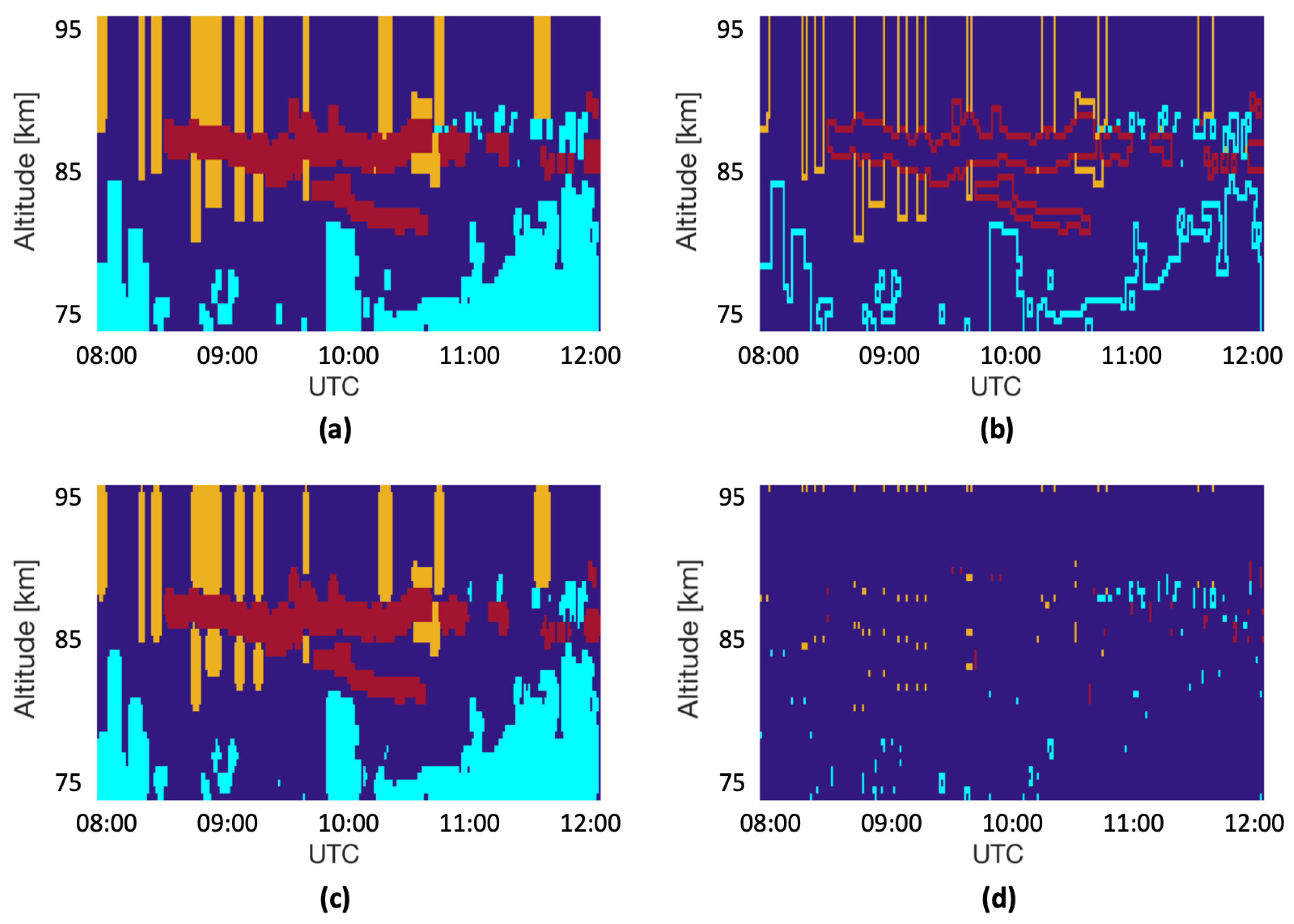
Next, we use the weighted-down technique described in Section 2.2 that aims to reduce both model bias and variance by reducing the weighting for pixel labels with large uncertainty and increasing it for labels with small uncertainty. For this, as a first step on the manually labeled data, for instance as shown in Figure 3a, we apply edge erosion to obtain a set of pixel labels that should be given lesser weight. As the labels we used in our experiment do not overlap, the edge erosion step generates a set of pixel labels along the label boundaries, as shown in Figure 3b. Finally, we calculate uncertainty scores based on Equation (3) in Section 2.2 for these pixel labels, and any pixel labels with non zero uncertainty scores are not kept for further analysis. Figure 3c shows the pixel labels after removing pixel labels with uncertainty, and Figure 3d shows the pixel labels that are removed from further analysis.

3.4. Random Forests Application

For our experiments, we employ random forests for training and evaluating the performance of data segmentation. For this we use MATLAB. The training is performed on an ensemble of bagged classification trees where number of trees in the forest is 500. In line with the study by Probst et al. [18] the number of trees is kept high, i.e., 500, samples are drawn with replacement, and p-value is used as the splitting rule. In addition, we enable surrogate decision split in order to allow the random forests to make a decision in case of missing data. This is done to accommodate for instances where we obtain missing amplitude values, i.e., NaNs in the data.

3.5. Feature Extraction

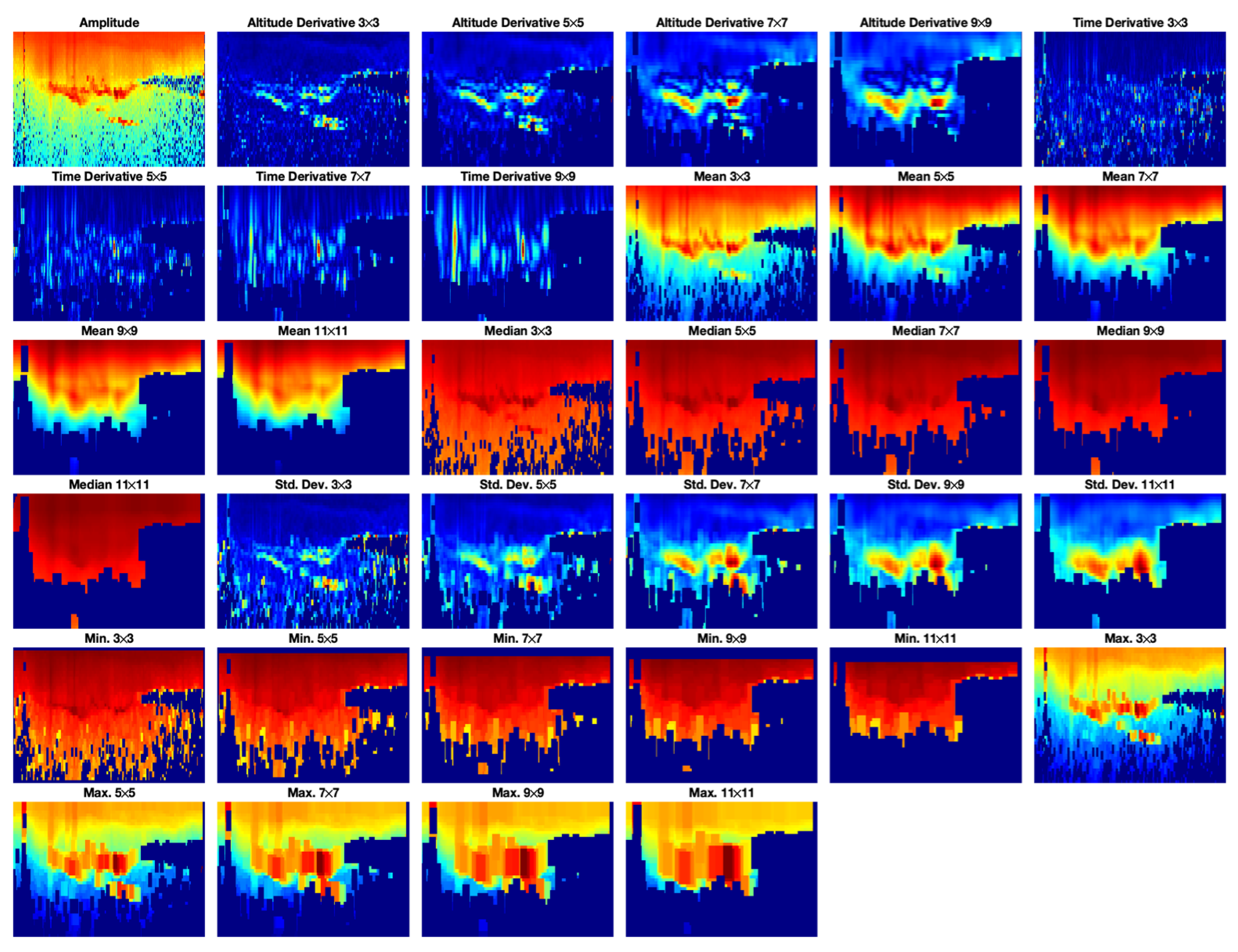
For each pixel, we extracted a dataset of features which is used as input together with its label. For each pixel we calculate features such as: mean, standard deviation, median, minimum and maximum values associated with neighborhoods ranging in sizes 3 × 3, 5 × 5, 7 × 7, 9 × 9, and 11 × 11 pixels where the pixel is at the center. In addition, we compute vertical and horizontal Gradient magnitudes using Sobel kernels for filter sizes 3 × 3, 5 × 5, 7 × 7, and 9 × 9, see [32]. Horizontal gradient operators calculate the time derivatives, and vertical gradient operators calculate the altitude derivatives. Furthermore, for each pixel its altitude and amplitude are included as features. This generates a feature vector with 35 dimensions. We plotted the different features extracted from the data in Figure 4 for the given observation day, 30 June 2008, except for altitude which is not illustrated in this figure. In the figure, the image in the first row and column represents the normalized amplitude. Then, from left to right and from top to bottom, the four next images represent the vertical gradient magnitudes for filter sizes of 3 × 3, 5 × 5, 7 × 7, and 9 × 9 pixels. The following four images represent the horizontal gradient magnitudes for the same filter sizes. The next five images represent the mean values for filters filter sizes of 3 × 3, 5 × 5, 7 × 7, 9 × 9, and 11 × 11 pixels. In a similar way, we represent the median values, the standard deviation, the minimum values, and finally the maximum values for the same filter sizes ranging from 3 × 3 to 11 × 11 pixels.

4. Results

The performance of random forests based on segmentation methods using different combinations of features, i.e., filter sizes, number of randomly selected features m t r y , can be seen in Table 2 and Table 3. While the results from using original labels are outlined in Table 2, the results we obtained using weighted-down labels (discussed in Section 3.3) are shown in Table 3. We evaluate the performance in terms of classification error for the test data, classification error for the out-of-bag (OOB) data samples, logarithmic error for the test data, logarithmic error for the out-of-bag (OOB) samples, Area under the ROC Curves (AUCs) for PMSE, Ionospheric background, and Noise. Note that for each filter size in the table, we use the following features: altitude derivative, time derivative, mean, median, standard deviation, minimum, and maximum. Additionally, we also use other features such as altitude and amplitude. This means that for each filter size, the feature vector has nine dimensions. At the filter size 11 × 11, the gradient filter is 9 × 9. For one filter size, e.g., 3 × 3 we use m t r y = 3, 6, 9. After that, we use all filter sizes and select m t r y = 5, 10, 15, 20, 25, 30 and 35, where 35 is the total length of the feature vector obtained from using all filter sizes.
The results for original labels can be seen in in Table 2 and the results for weighted-down labels can be found in Table 3. In both cases, the logarithmic error and logarithmic error OOB have the best performance for a filter size of 7 × 7 pixels with m t r y = 9, and the worst one for all filter sizes and an m t r y = 5. The classification error and the classification error OOB have the best results for the filter size 3 × 3 associated with m t r y = 3 for original labels, or the filter size 7 × 7 associated with m t r y = 9 and the filter size 11 × 11 with m t r y = 6 for the weighted-down labels. The worst performance on the other hand was obtained in the case using all filter sizes and m t r y = 5, and the filter size 9 × 9 in combination with m t r y = 3. Almost all the AUC curves had the best performance for the combination of the filter size 6 × 6 with an m t r y = 6. The only exception is the AUC Ion. Back. metric with original labels, for which the best performance was obtained for a filter size of 5 × 5 pixels with m t r y = 6. We see that for all filter sizes, i.e., 35-dimensional feature vector and m t r y = 5, 10, 15, 20, there are slight improvements in the performance for the scores associated with different evaluation metrics. This can possibly indicate that the performance of the random forests algorithm benefits from multi-resolution features extracted using the different filter sizes. However, the performance decreases when all the filter sizes are used and an m t r y equal to 35.
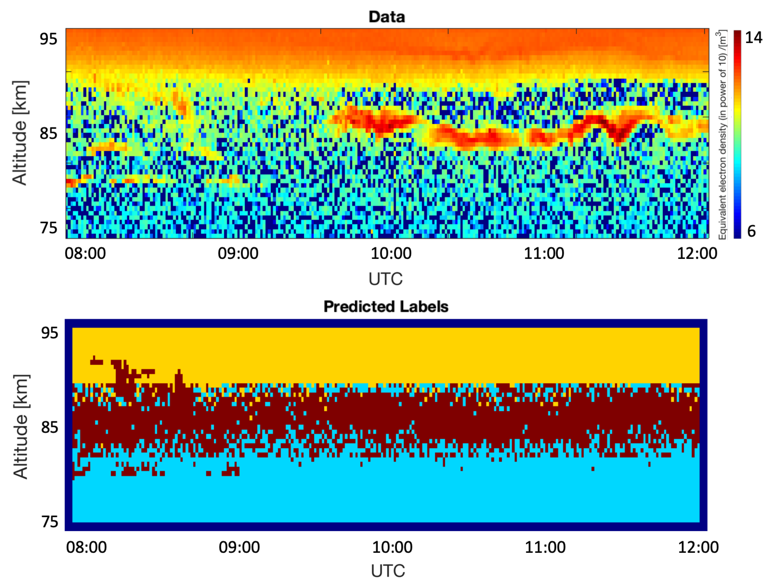
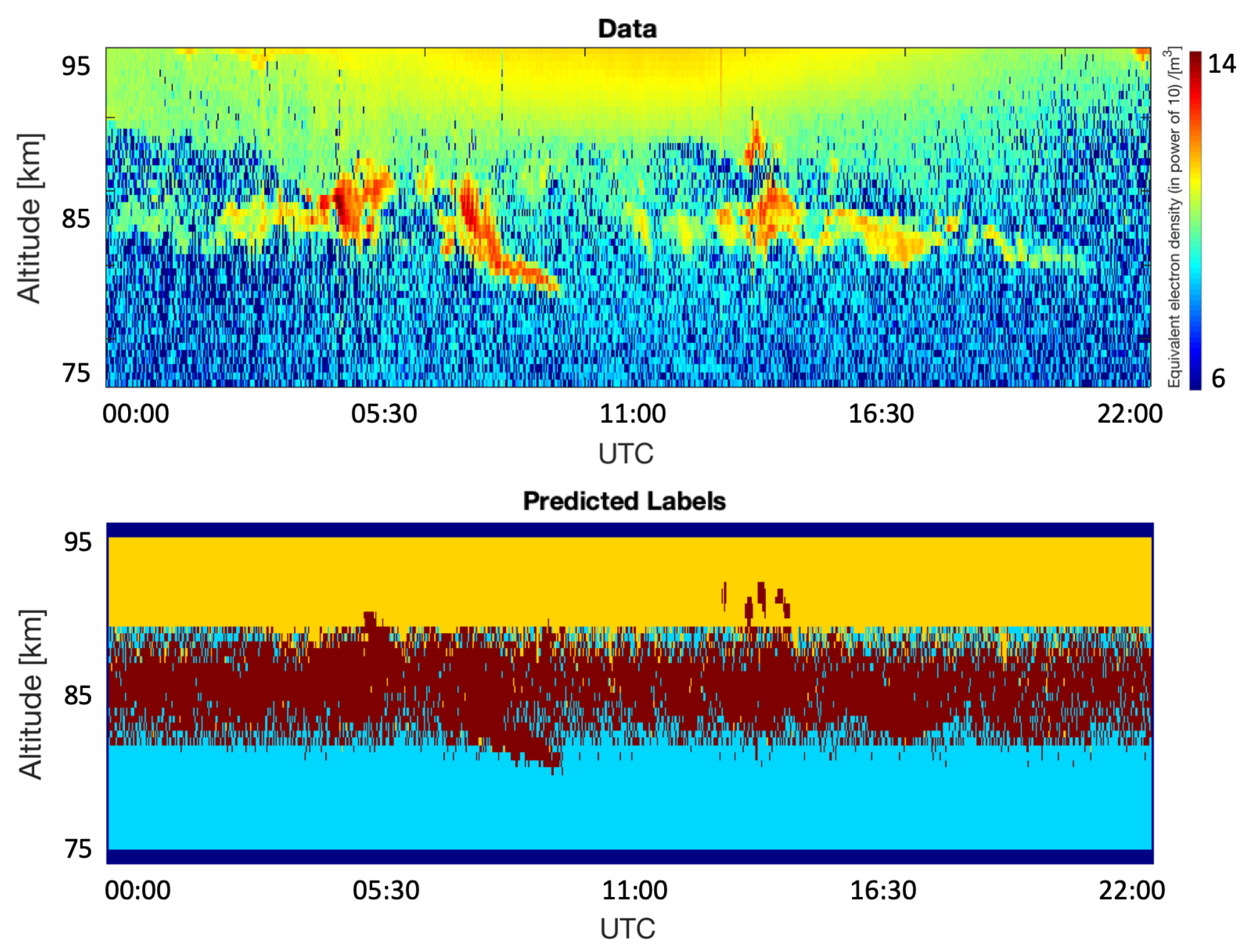
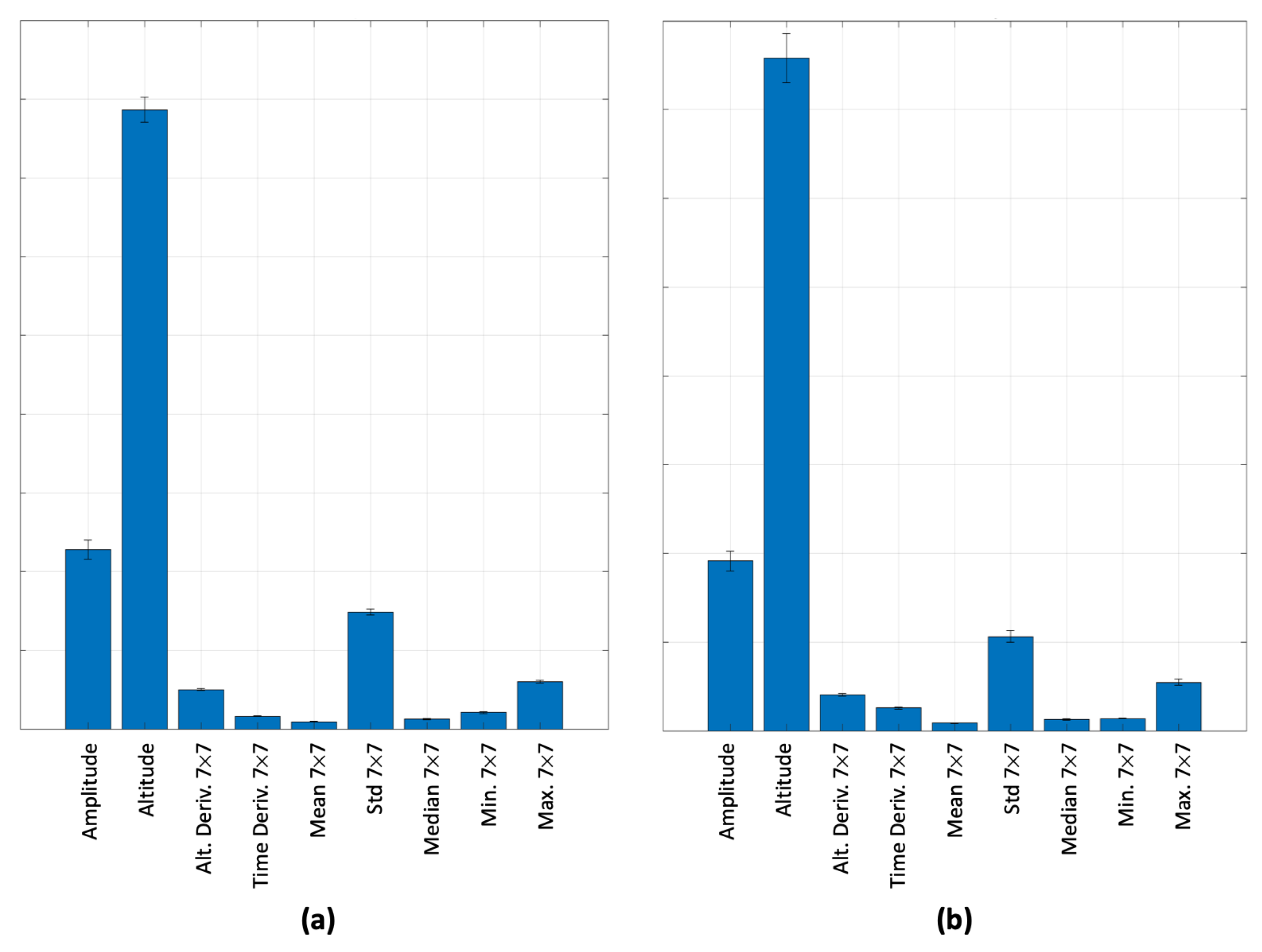
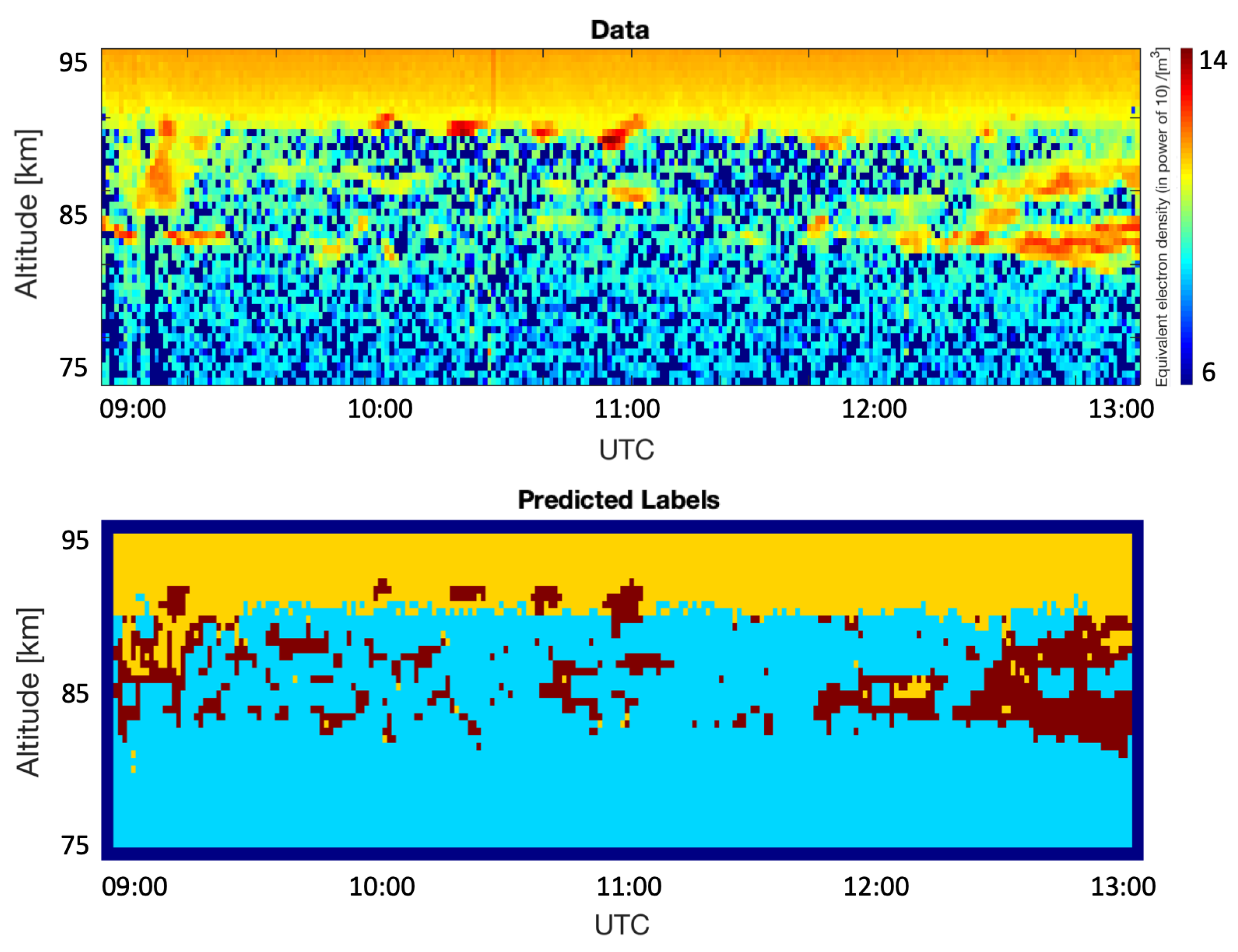
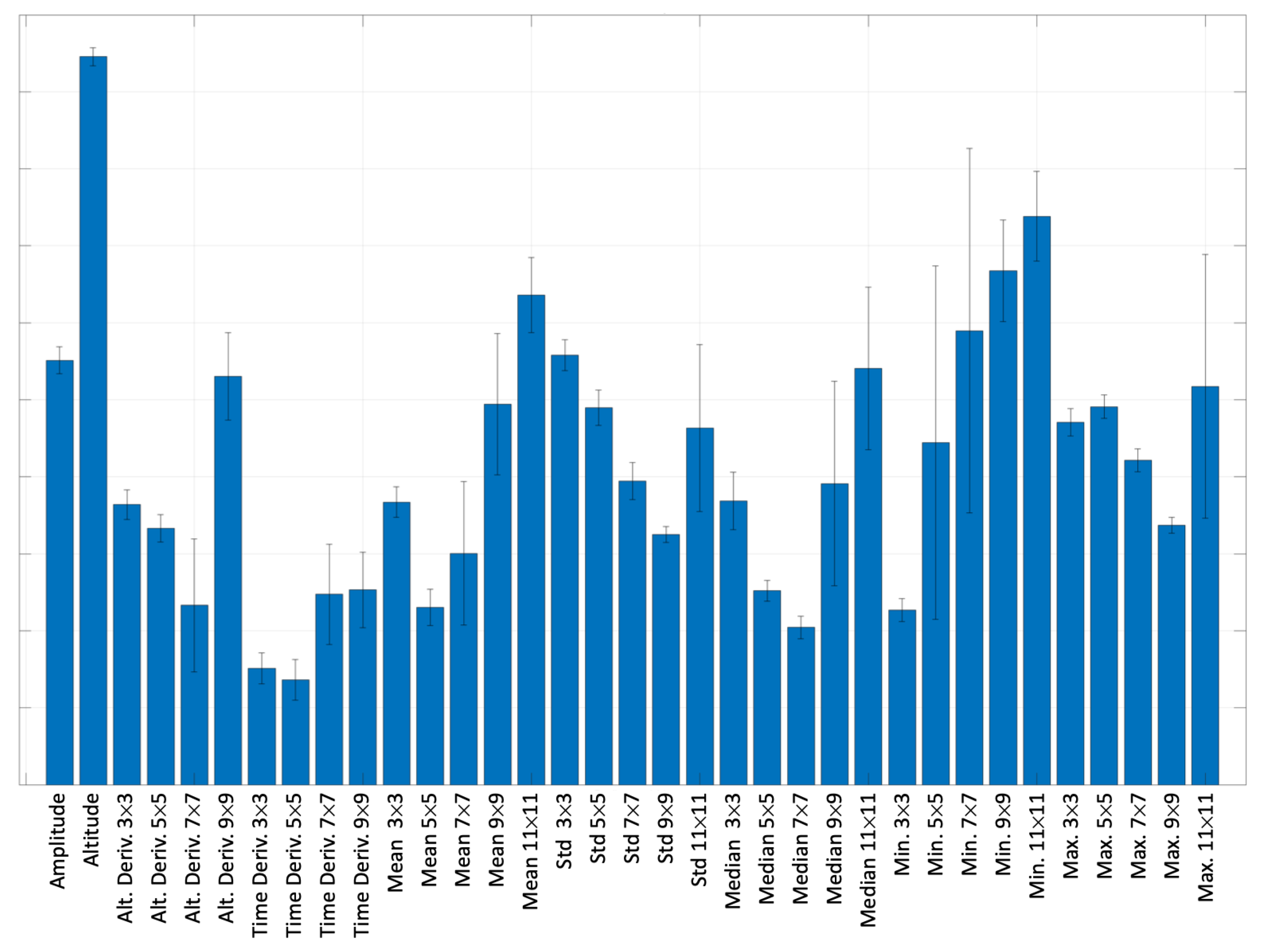
Based on the results obtained in Table 2 and Table 3, we choose the filter size 7 × 7 and m t r y = 9 for qualitative analysis. We used this classification model on 30 images, out of which 12 were new data for the model. Figure 5, Figure 6, Figure 7 and Figure 8 show the predicted labels for the classification model (with a filter size 7 × 7 and m t r y = 9). In all four cases, the prediction of PMSE labels by the model looks poor. Figure 9 shows the predictor importance for both original (a) and weighted-down (b) labels. We can see that in both cases, the altitude is clearly dominating over the other features. The importance value in the vertical axis is using an arbitrary scale, and the results were averaged over 10 iterations. The error bars represent one standard deviation from the average.
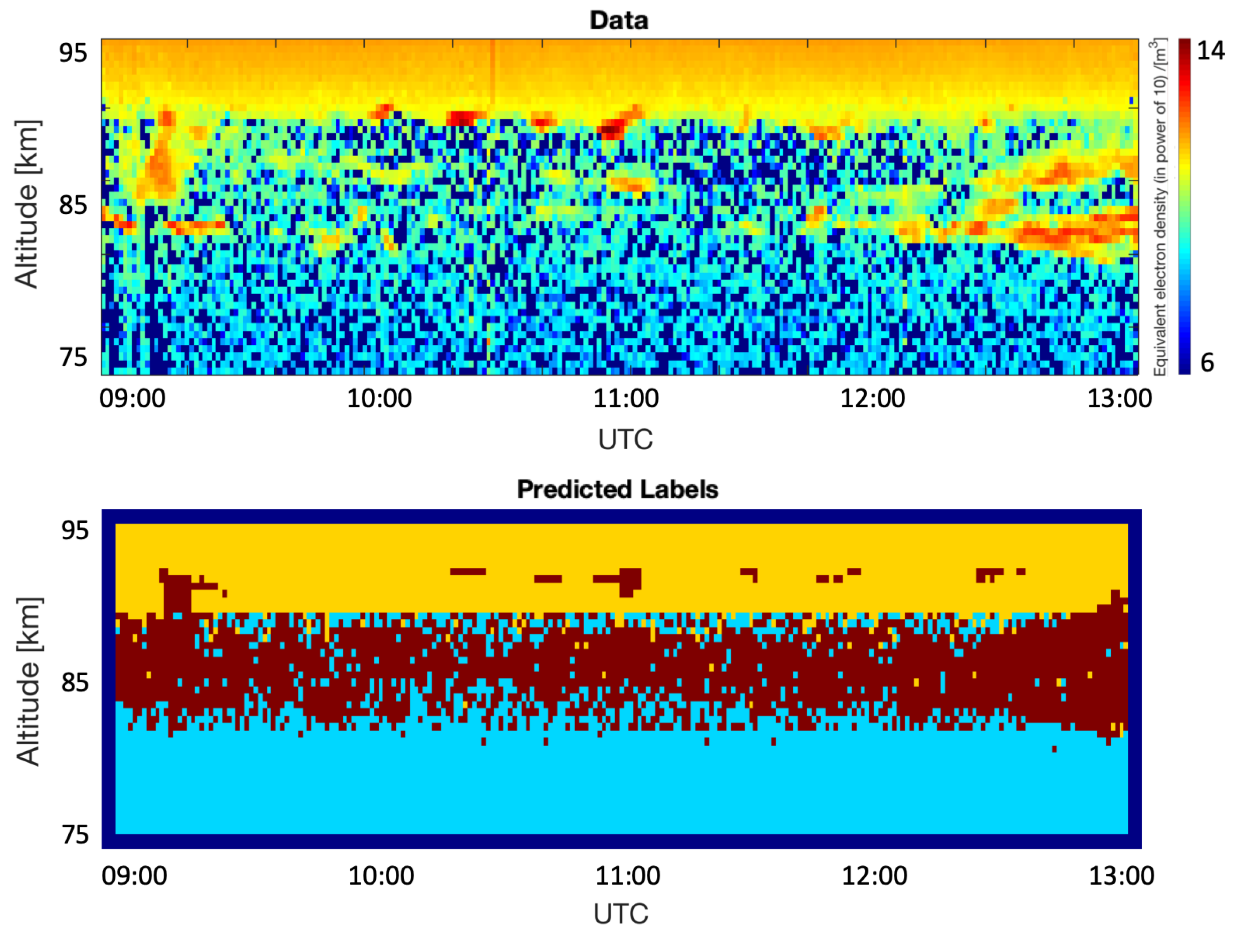
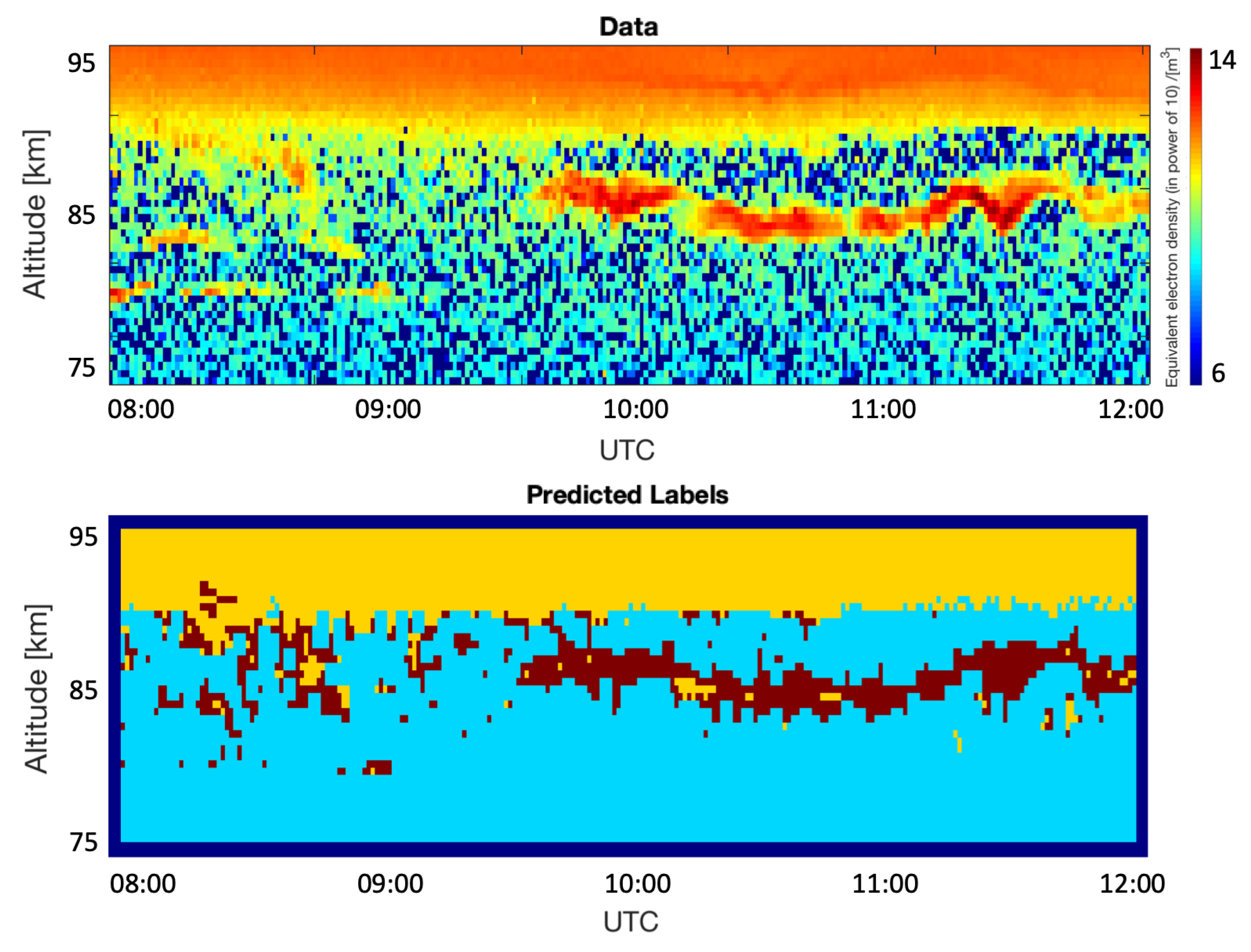
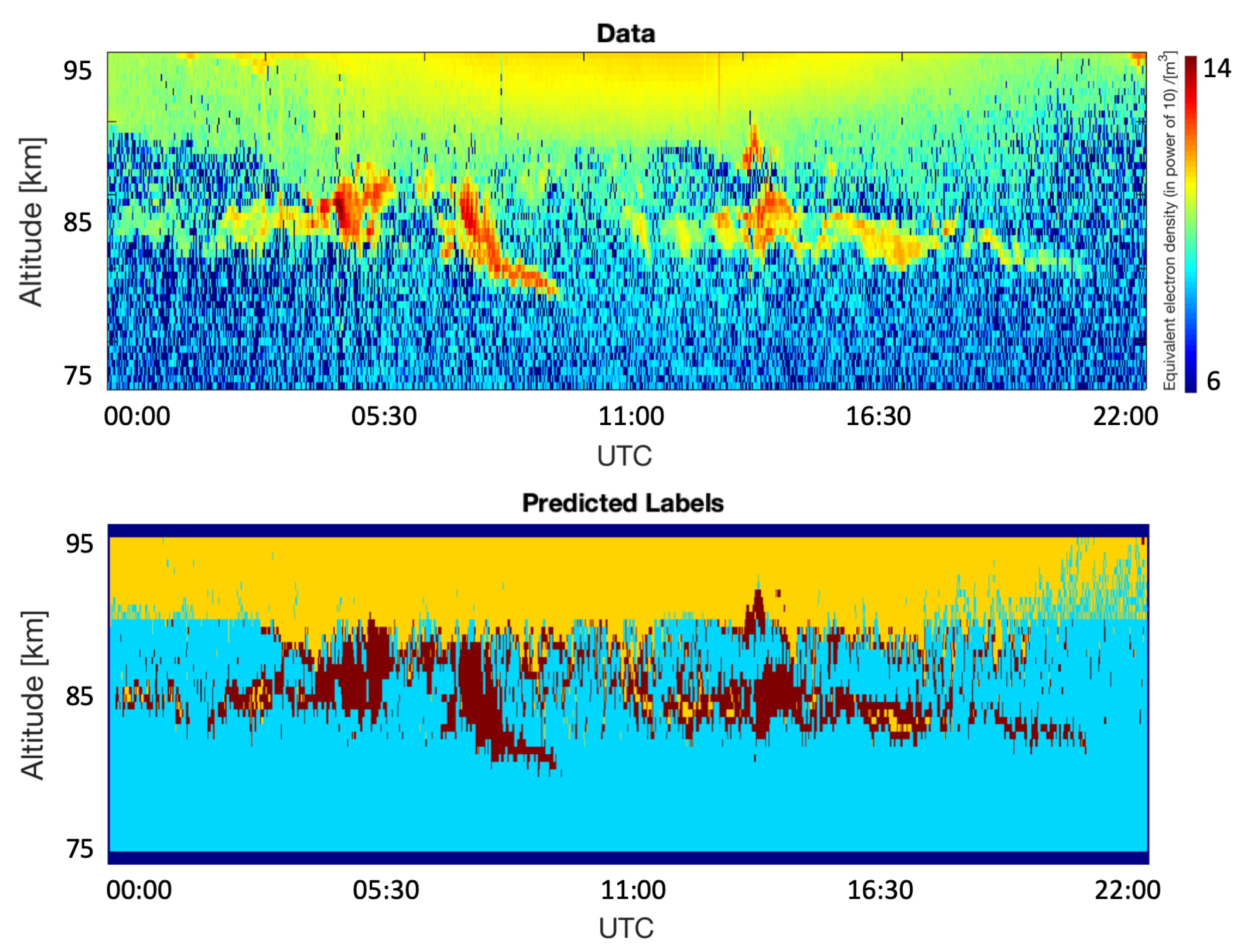
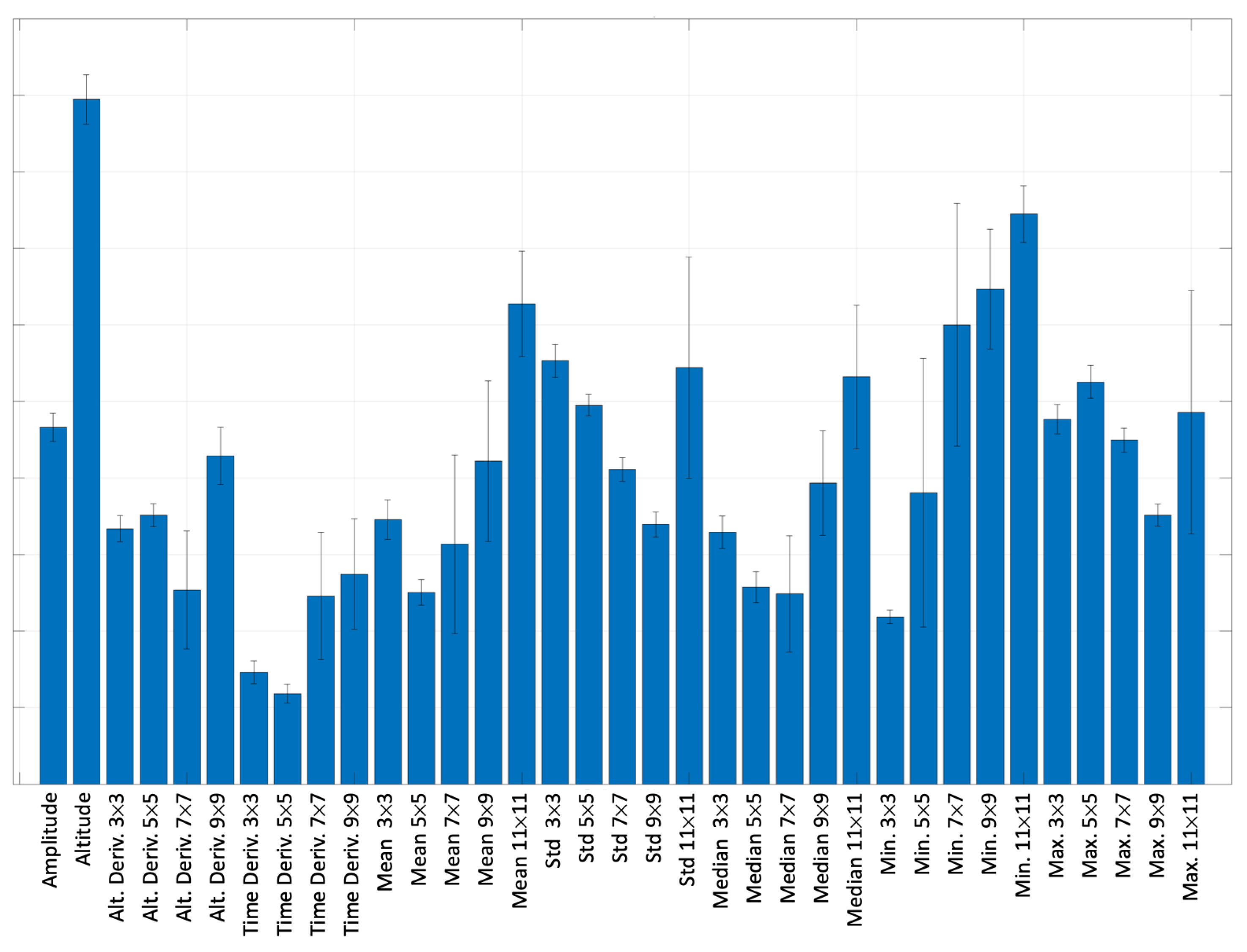
For qualitative testing, the predicted labels were generated for all the 30 test images and for all the cases (all filter sizes and all m t r y values) shown in both Table 2 and Table 3. Although in Table 2 and Table 3, the values of classification error, classification error OOB, logarithmic error and logarithmic error OOB are worse for all filter sizes and m t r y = 5, these parameters gave us the best predicted labels. To illustrate our qualitative analysis, we use four examples. The predicted labels that we observed were the best (all filter sizes and m t r y = 5) are shown in Figure 10, Figure 11, Figure 12 and Figure 13. These figures show the predicted labels for the same time and dates as Figure 5, Figure 6, Figure 7 and Figure 8. Figure 14 and Figure 15 show the corresponding predictors importance for, respectively, original labels and weighted-down labels in the case of using all filter sizes together with m t r y = 5. The results were averaged over 10 iterations, and the error bars represent one standard deviation from the average.
In Table 3, the evaluation scores for all combinations of filter sizes are slightly better than the evaluation scores in Table 2. This can imply that by employing weighted-down labels (discussed in Section 3.3), we can achieve a reduction in both model bias and variance, hence, leading to an improved performance. Although the performance gain achieved using weighted-down labels technique from the study by [6] is marginal, for further studies involving data labels beyond the three categories used in this paper, the gains achieved using the weighted-down labels technique could be significant.
When all 35 features are used as predictors, i.e., m t r y = 35, one can see that their importance is varying with different filter sizes. We can note that when original labels are used for the random forests algorithm, the predictor importance is different (as shown in Figure 14) as compared to when we use the weighted-down labels (as shown in Figure 15). The importance of all the different predictors is plotted on an arbitrary scale which is linear and relative. One can note that in Figure 14, the most important feature is altitude which is something that is also used in practice to determine if a signal is PMSE. After that, the second most important feature is the 11 × 11 minimum value, followed by the 9 × 9 minimum value, and then the 11 × 11 mean value, and so on. The importance of features is similar for the weighted-down labels case as shown in Figure 15, where the first 6 predictors are the same. After that, the order is slightly different. This implies that features extracted across multiple scales, i.e., ranging from 3 × 3 to 11 × 11 can play an important role in improving the prediction of the random forests. Finally, one can see that in Figure 15, the error bars are slightly smaller using weighted-down labels compared to Figure 14, where original labels are used.

5. Discussion

In the case with the filter size 7 × 7 and m t r y = 9 which quantitatively gives the best results, the segmentation results as shown in Figure 5, Figure 6, Figure 7 and Figure 8 are worse. This could be due to its poor generalization to new unseen data. Based on the segmentation results obtained in Figure 10, Figure 11, Figure 12 and Figure 13, we can note that using the random forests for all filter sizes with m t r y = 5 and weighted-down labels technique from the study by Almeida et al. [6], it is possible to segment the data into the three different categories of interest. Furthermore, m t r y = 5 is in line with the study by Probst et al. [18], which suggests that the recommended number of predictors is approximately equal to the square root value of the total number of features, which is 35 in our case.
In one of the images used for qualitative testing, for instance Figure 13, we notice an unusual case where part of the PMSE signal is not accurately segmented. We observe that some pixels were classified as PMSE at the border between the Ionospheric background and the Background noise. This happens around 11:00 to 12:00 UTC, while we can clearly see that there is no PMSE at that time on the original image above. We think this is the result of the fact that PMSE are usually having a pattern elongated horizontally. Because of this, the model might make the horizontal patterns stand out more, and therefore give more importance to the vertical gradients, hence to the altitude derivatives. This is something that Figure 14 and Figure 15 confirm, where altitude derivatives were given more importance than the time derivatives. In the future, we aim to use this segmentation approach to extract the PMSE signal from the vast dataset of EISCAT observations in order to analyze in detail the structures of the PMSE signals and compare the PMSE signals from different time periods in the solar cycle.

6. Conclusions

This study outlines a framework to segment PMSE from the Ionospheric background and the Background noise in images obtained from EISCAT VHF radar data. We manually labeled the data into three different categories: PMSE, Ionospheric background, and Background noise, representing in total a dataset of 56,250 labeled samples. For segmentation, we employed random forests on a set of simple features. These features include: altitude derivative, time derivative, mean, median, standard deviation, minimum, and maximum values corresponding to neighborhood sizes ranging from 3 by 3 to 11 by 11. We also used the amplitude and altitude additionally as features. Next, we used a weighting-down technique on the data labels to reduce the model bias and variance.
First, our results show that it is possible to extract PMSE signal from the data, when using all sizes for feature extraction and m t r y = 5. Second, by employing the weighted-down labels technique, we note an improvement in the performance of random forests.
For future studies, PMSE could be investigated over a broader dataset comprising several years of observations for one complete solar cycle. Information such as the thickness or shape of PMSE over the years could also be analyzed to gain further understanding of its origin and evolution.

Author Contributions

Conceptualization, D.J., P.S., I.M. and U.-P.H.; Data curation, D.J.; Funding acquisition, I.M.; Investigation, D.J. and P.S.; Project administration, I.M.; Software, D.J. and P.S.; Supervision, P.S., I.M. and U.-P.H.; Validation, P.S., I.M. and U.-P.H.; Writing—original draft, D.J.; Writing—review & editing, D.J., P.S., I.M. and U.-P.H. All authors have read and agreed to the published version of the manuscript.

Funding

This work was carried out within a project funded by Research Council of Norway, NFR 275503. The Norwegian participation in EISCAT and EISCAT3D is funded by Research Council of Norway, through research infrastructure grant 245683. The EISCAT International Association is supported by research organizations in Norway (NFR), Sweden (VR), Finland (SA), Japan (NIPR and STEL), China (CRIPR), and the United Kingdom (NERC).

Data Availability Statement

EISCAT VHF and UHF data are available under http://www.eiscat.se/madrigal/ (accessed on 15 June 2022).

Acknowledgments

The authors thank the Research Council of Norway for the funding and the EISCAT International Association which is supported by research organizations in Norway (NFR), Sweden (VR), Finland (SA), Japan (NIPR and STEL), China (CRIPR), and the United Kingdom (NERC) for making the data easily accessible.

Conflicts of Interest

The authors declare no conflict of interest. The funders had no role in the design of the study; in the collection, analyses, or interpretation of data; in the writing of the manuscript, or in the decision to publish the results.

References

  1. Latteck, R.; Renkwitz, T.; Chau, J.L. Two decades of long-term observations of polar mesospheric echoes at 69°N. J. Atmos. Sol.-Terr. Phys. 2021, 216, 105576. [Google Scholar] [CrossRef]
  2. Cho, J.Y.N.; Röttger, J. An updated review of polar mesosphere summer echoes: Observation, theory, and their relationship to noctilucent clouds and subvisible aerosols. J. Geophys. Res. Atmos. 1997, 102, 2001–2020. [Google Scholar] [CrossRef] [Green Version]
  3. Rapp, M.; Lübken, F.J. Polar mesosphere summer echoes (PMSE): Review of observations and current understanding. Atmos. Chem. Phys. 2004, 4, 2601–2633. [Google Scholar] [CrossRef] [Green Version]
  4. Avaste, O. Noctilucent clouds. J. Atmos. Terr. Phys. 1993, 55, 133–143. [Google Scholar] [CrossRef]
  5. Gadsden, M. A secular change in noctilucent cloud occurrence. J. Atmos. Terr. Phys. 1990, 52, 247–251. [Google Scholar] [CrossRef]
  6. Almeida, M.; Zhuang, Y.; Ding, W.; Crouter, S.E.; Chen, P. Mitigating Class-Boundary Label Uncertainty to Reduce Both Model Bias and Variance. ACM Trans. Knowl. Discov. Data 2021, 15, 27. [Google Scholar] [CrossRef]
  7. Mann, I.; Häggström, I.; Tjulin, A.; Rostami, S.; Anyairo, C.C.; Dalin, P. First wind shear observation in PMSE with the tristatic EISCAT VHF radar. J. Geophys. Res. Space Phys. 2016, 121, 11271–11281. [Google Scholar] [CrossRef]
  8. Ecklund, W.L.; Balsley, B.B. Long-term observations of the Arctic mesosphere with the MST radar at Poker Flat, Alaska. J. Geophys. Res. Space Phys. 1981, 86, 7775–7780. [Google Scholar] [CrossRef]
  9. Hoppe, U.P.; Hall, C.; Röttger, J. First observations of summer polar mesospheric backscatter with a 224 MHz radar. Geophys. Res. Lett. 1988, 15, 28–31. [Google Scholar] [CrossRef]
  10. Hocking, W.; Rüster, R.; Czechowsky, P. Absolute reflectivities and aspect sensitivities of VHF radio wave scatterers measured with the SOUSY radar. J. Atmos. Terr. Phys. 1986, 48, 131–144. [Google Scholar] [CrossRef]
  11. Kaminski, B.; Jakubczyk, M.; Przemyslaw, S. A framework for sensitivity analysis of decision trees. Cent. Eur. J. Oper. Res. 2018, 26, 135–159. [Google Scholar] [CrossRef] [PubMed]
  12. Quinlan, J.R. Induction of Decision Trees. Mach. Learn. 1986, 1, 81–106. [Google Scholar] [CrossRef] [Green Version]
  13. Quinlan, J.R. C4.5: Programs for Machine Learning; Morgan Kaufmann Publishers Inc.: San Francisco, CA, USA, 1993. [Google Scholar]
  14. Kuhn, M.; Johnson, K. Applied Predictive Modeling; Springer: New York, NY, USA, 2013. [Google Scholar]
  15. Breiman, L.; Friedman, J.H.; Olshen, R.A.; Stone, C.J. Classification and Regression Trees; Chapman and Hall/CRC: Monterey, CA, USA, 1984. [Google Scholar]
  16. James, G.; Witten, D.; Hastie, T.; Tibshirani, R. An Introduction to Statistical Learning: With Applications in R; Springer Publishing Company, Incorporated: New York, NY, USA, 2014. [Google Scholar]
  17. Cutler, A.; Cutler, D.R.; Stevens, J.R. Random Forests. In Ensemble Machine Learning: Methods and Applications; Zhang, C., Ma, Y., Eds.; Springer: Boston, MA, USA, 2012; pp. 157–175. [Google Scholar] [CrossRef]
  18. Probst, P.; Wright, M.N.; Boulesteix, A.L. Hyperparameters and tuning strategies for random forest. WIREs Data Min. Knowl. Discov. 2019, 9, e1301. [Google Scholar] [CrossRef] [Green Version]
  19. Grömping, U. Variable Importance Assessment in Regression: Linear Regression versus Random Forest. Am. Stat. 2009, 63, 308–319. [Google Scholar] [CrossRef]
  20. Karpievitch, Y.V.; Hill, E.G.; Leclerc, A.P.; Dabney, A.R.; Almeida, J.S. An Introspective Comparison of Random Forest-Based Classifiers for the Analysis of Cluster-Correlated Data by Way of RF++. PLoS ONE 2009, 4, e7087. [Google Scholar] [CrossRef] [Green Version]
  21. Breiman, L. Random Forests. Mach. Learn. 2001, 45, 5–32. [Google Scholar] [CrossRef] [Green Version]
  22. Tyralis, H.; Papacharalampous, G.; Langousis, A. A Brief Review of Random Forests for Water Scientists and Practitioners and Their Recent History in Water Resources. Water 2019, 11, 910. [Google Scholar] [CrossRef] [Green Version]
  23. Ristin, M.; Guillaumin, M.; Gall, J.; Van Gool, L. Incremental Learning of Random Forests for Large-Scale Image Classification. IEEE Trans. Pattern Anal. Mach. Intell. 2016, 38, 490–503. [Google Scholar] [CrossRef]
  24. Gall, J.; Razavi, N.; Van Gool, L. An Introduction to Random Forests for Multi-class Object Detection. In Outdoor and Large-Scale Real-World Scene Analysis; Dellaert, F., Frahm, J.M., Pollefeys, M., Leal-Taixé, L., Rosenhahn, B., Eds.; Springer: Berlin/Heidelberg, Germany, 2012; pp. 243–263. [Google Scholar]
  25. Belgiu, M.; Drăguţ, L. Random forest in remote sensing: A review of applications and future directions. ISPRS J. Photogramm. Remote Sens. 2016, 114, 24–31. [Google Scholar] [CrossRef]
  26. Mahapatra, D. Analyzing Training Information From Random Forests for Improved Image Segmentation. IEEE Trans. Image Process. 2014, 23, 1504–1512. [Google Scholar] [CrossRef]
  27. Probst, P.; Boulesteix, A.L. To Tune or Not to Tune the Number of Trees in Random Forest. J. Mach. Learn. Res. 2017, 18, 6673–6690. [Google Scholar]
  28. MathWorks. Available online: https://se.mathworks.com/help/stats/compactclassificationensemble.loss.html (accessed on 8 July 2021).
  29. Fawcett, T. An introduction to ROC analysis. Pattern Recognit. Lett. 2006, 27, 861–874. [Google Scholar] [CrossRef]
  30. Jozwicki, D.; Sharma, P.; Mann, I. Investigation of Polar Mesospheric Summer Echoes Using Linear Discriminant Analysis. Remote Sens. 2021, 13, 522. [Google Scholar] [CrossRef]
  31. Lehtinen, M.S.; Huuskonen, A. General incoherent scatter analysis and GUISDAP. J. Atmos. Terr. Phys. 1996, 58, 435–452. [Google Scholar] [CrossRef]
  32. Doug Morris, R.R. Sobel gradient kernels (3 × 3, 5 × 5, 7 × 7, 9 × 9). Available online: https://imagej.nih.gov/nih-image/download/user-macros/slowsobel.macro (accessed on 11 May 2021).
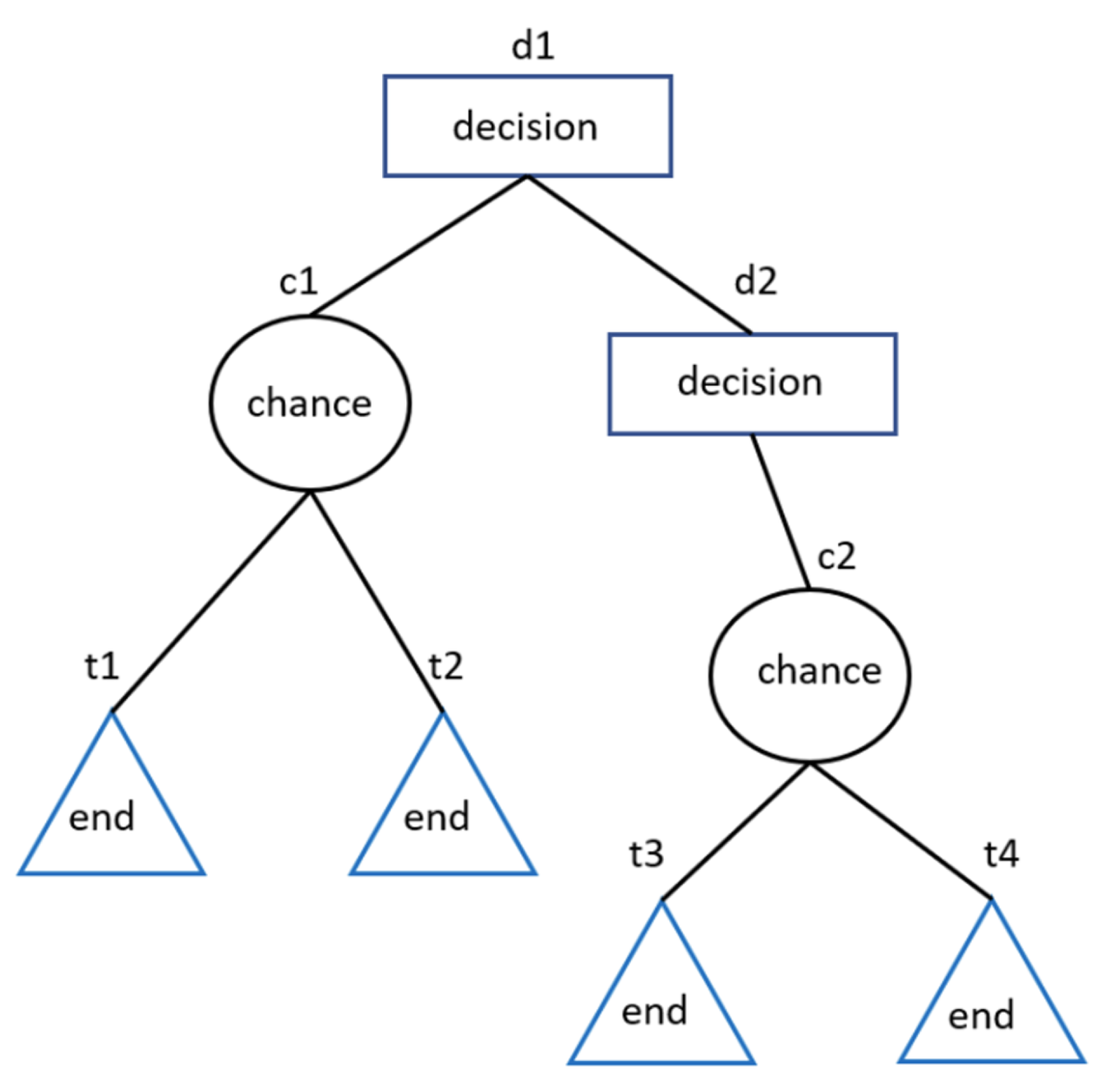
Figure 1. Example of a decision tree with decision, chance, and terminal or end nodes.
Remotesensing 14 02976 g001
Figure 2. An example for manual labeling of the observations from 30 June 2008. The altitude range varies from 75 km to 95 km. The observation starts at 08:00 UTC and finishes at 12:00 UTC. The color scale in the original image represents the equivalent electron density to the power of 10, per cubic meter. In the labels part, the cyan, yellow and dark red color represent, respectively, the Background noise, Ionospheric background, and PMSE classes. The dark blue color represents unlabeled data.
Remotesensing 14 02976 g002
Figure 3. Prepossessing step with the labels: (a) shows the original labels, (b) shows the contours of the labels, (c) shows the image after removing the labeled pixels using weighted-down labels technique, and (d) shows the removed labeled pixels. For all four images, the red colored pixels belong to the PMSE class, the yellow pixels represent the Ionospheric background, and the cyan pixels belong to the Background noise class. Finally, the dark blue pixels represent unlabeled data. All of the plots have the same axes: the horizontal axis represents the time which starts at 8:00 UTC and finishes at 12:00 UTC. The vertical axis represents the altitude which ranges from 75 km to 95 km. The chosen observation day is 30 June 2008.
Remotesensing 14 02976 g003
Figure 4. Visualization of the different features extracted from the data (with the exception of altitude) in the form of heat maps where red pixels correspond to highest values, blue pixels correspond to lowest values, and yellow pixels represent the values in between. The rows in the figure represent the different features, and the columns represent the different filter sizes that were used. All 34 plots have the same axes: the horizontal axis represents the time which starts at 8:00 UTC and finishes at 12:00 UTC. The vertical axis represents the altitude which ranges from 75 km to 95 km. The observation day chosen in this figure is 30 June 2008.
Remotesensing 14 02976 g004
Figure 5. Results of segmentation using the random forests method with the 7 × 7 filter size, weighted-down labels, and m t r y = 9. The weighted-down labels technique is taken from the study by [6]. The data are obtained from the observation day, 17 July 2009. The image on the top illustrates the original image where the color scale represents the equivalent electron density to the power of 10, per cubic meter. The image at the bottom represents the predicted labels. Yellow, cyan and dark red represents, respectively, the region of the image labeled as Ionospheric background, Background noise, and PMSE. The horizontal axis on both images represents the time which starts at 8:00 UTC and finishes at 12:00 UTC. The vertical axis represents the altitude which ranges from 75 km to 95 km.
Remotesensing 14 02976 g005
Figure 6. Results of segmentation using the random forests method with the 7 × 7 filter size, weighted-down labels, and m t r y = 9. The weighted-down labels technique is taken from the study by [6]. The data are obtained from the observation day, 8 July 2010. The image on the top illustrates the original image where the color scale represents the equivalent electron density to the power of 10, per cubic meter. The image at the bottom represents the predicted labels. Yellow, cyan and dark red represents, respectively, the region of the image labeled as Ionospheric background, Background noise, and PMSE.The horizontal axis on both images represents the time which starts at 9:00 UTC and finishes at 13:00 UTC. The vertical axis represents the altitude which ranges from 75 km to 95 km.
Remotesensing 14 02976 g006
Figure 7. Results of segmentation using the random forests method with the 7 × 7 filter size, weighted-down labels, and m t r y = 9. The weighted-down labels technique is taken from the study by [6]. The data are obtained from the observation day, 7 July 2010. The image on the top illustrates the original image where the color scale represents the equivalent electron density to the power of 10, per cubic meter. The image at the bottom represents the predicted labels. Yellow, cyan and dark red represents, respectively, the region of the image labeled as Ionospheric background, Background noise, and PMSE.The horizontal axis on both images represents the time which starts at 00:00 UTC and finishes at 22:00 UTC. The vertical axis represents the altitude which ranges from 75 km to 95 km.
Remotesensing 14 02976 g007
Figure 8. Results of segmentation using the random forests method with the 7 × 7 filter size, weighted-down labels, and m t r y = 9. The weighted-down labels technique is taken from the study by [6]. The data are obtained from the observation day, 30 June 2008. The image on the top illustrates the original image where the color scale represents the equivalent electron density to the power of 10, per cubic meter. The image at the bottom represents the predicted labels. Yellow, cyan and dark red represents, respectively, the region of the image labeled as Ionospheric background, Background noise, and PMSE.The horizontal axis on both images represents the time which starts at 8:00 UTC and finishes at 12:00 UTC. The vertical axis represents the altitude which ranges from 75 km to 95 km.
Remotesensing 14 02976 g008
Figure 9. Predictor importance for random forests used on original (a) and weighted-down (b) labels with a 7 × 7 filter size and m t r y = 9. The horizontal axis lists all the predictors, and the vertical axis shows their importance using an arbitrary scale. Higher values mean that the algorithm assigned to them a higher importance to classify the data efficiently. These values are averaged over 10 iterations, and the error bars represent one standard deviation from the average.
Remotesensing 14 02976 g009
Figure 10. Results of segmentation using the random forests method ( m t r y = 5) and weighted-down labels technique from the study by [6]. The data are obtained from the observation day on the 17 July 2009. The image on the top illustrates the original image where the color scale represents the equivalent electron density to the power of 10, per cubic meter. The image at the bottom represents the predicted labels. Yellow, cyan and dark red represents, respectively, the region of the image labeled as Ionospheric background, Background noise, and PMSE.The horizontal axis on both images represents the time which starts at 7:50 UTC finishes at 12:00 UTC. The vertical axis represents the altitude which ranges from 75 km to 95 km.
Remotesensing 14 02976 g010
Figure 11. Results of segmentation using the random forests method ( m t r y = 5) and weighted-down labels technique from the study by [6]. The data are obtained from the observation day, 7 July 2010. The image on the top illustrates the original image where the color scale represents the equivalent electron density to the power of 10, per cubic meter. The image at the bottom represents the predicted labels. Yellow, cyan and dark red represent, respectively, the region of the image labeled as Ionospheric background, Background noise, and PMSE.The horizontal axis on both images represents the time which starts at 00:00 UTC and finishes at 22:00 UTC. The vertical axis represents the altitude which ranges from 75 km to 95 km.
Remotesensing 14 02976 g011
Figure 12. Results of segmentation using the random forests method ( m t r y = 5) and weighted-down labels technique from the study by [6]. The data are obtained from the observation day of 8 July 2010. The image on the top illustrates the original image where the color scale represents the equivalent electron density to the power of 10, per cubic meter. The image at the bottom represents the predicted labels. Yellow, cyan and dark red represents, respectively, the region of the image labeled as Ionospheric background, Background noise, and PMSE. The horizontal axis on both images represents the time which starts at 09:00 UTC and finishes at 13:00 UTC. The vertical axis represents the altitude which ranges from 75 km to 95 km.
Remotesensing 14 02976 g012
Figure 13. Results of segmentation using the random forests method ( m t r y = 5) and weighted-down labels technique from the study by [6]. The data are obtained from the observation day, 30 June 2008. The image on the top illustrates the original image where the color scale represents the equivalent electron density to the power of 10, per cubic meter. The image at the bottom represents the predicted labels. Yellow, cyan and dark red represents, respectively, the region of the image labeled as Ionospheric background, Background noise, and PMSE.The horizontal axis on both images represents the time which starts at 8:00 UTC and finishes at 12:00 UTC. The vertical axis represents the altitude which ranges from 75 km to 95 km.
Remotesensing 14 02976 g013
Figure 14. Predictor importance for random forests used on original labels with all filter sizes and m t r y = 5. The horizontal axis lists all the predictors, and the vertical axis shows their importance using an arbitrary scale.Higher values mean that the algorithm assigned to them a higher importance to classify the data efficiently. These values are averaged over 10 iterations, and the error bars represent one standard deviation from the average.
Remotesensing 14 02976 g014
Figure 15. Predictor importance for random forests used on weighted-down labels with all filter sizes and m t r y = 5. The horizontal axis lists all the predictors, and the vertical axis shows their importance using an arbitrary scale. Higher values mean that the algorithm assigned to them a higher importance to classify the data efficiently. These values are averaged over 10 iterations, and the error bars represent one standard deviation from the average.
Remotesensing 14 02976 g015
Table 1. This table lists the observation dates, given in (day. month. year), that are used for this study. The observation time is given in Universal time (UTC) in the format (hour: minutes: seconds).
DatesStart Time in UTCEnd Time in UTC
(dd:mm:yyyy)(hh:mm:ss)(hh:mm:ss)
28 June 200807:58:3308:36:18
30 June 200807:59:3812:07:30
02 July 200810:24:3011:59:02
10 June 200909:03:4211:56:09
14 July 200908:19:3311:33:15
16 July 200908:47:3010:06:26
17 July 200907:49:4411:59:30
30 July 200912:15:2915:59:08
06 July 201007:00:3023:59:30
07 July 201000:00:3021:59:27
08 July 201009:00:4212:59:03
09 July 201009:00:2412:59:09
01 June 201108:34:3110:02:07
08 June 201107:23:5013:01:07
09 June 201108:01:4512:59:26
12 June 201207:13:3123:59:28
29 June 201210:21:5710:30:04
11 July 201207:54:5713:09:40
13 June 201307:12:3308:59:26
28 June 201307:02:4312:58:28
12 July 201300:00:2821:58:28
27 July 201308:56:3613:05:14
27 June 201409:03:4812:59:38
01 July 201409:00:3613:00:24
22 July 201422:26:3323:59:28
23 July 201400:00:2809:26:28
10 August 201509:14:4016:12:28
12 August 201520:04:4023:59:28
13 August 201500:00:2801:59:26
20 August 201500:00:2801:59:26
Table 2. Results of the classification using original labels. These values are obtained after five iterations of each experiment. Each field contains the mean over these five iterations, followed by one standard deviation.
Logarithmic ErrorLogarithmic Error OOBClassification ErrorClassification Error OOBAUC Ion. Back.AUC NoiseAUC PMSE
Filter SizemtryMeanStdMeanStdMeanStdMeanStdMeanStdMeanStdMeanStd
3 × 330.394680.001150.394550.001120.104980.000180.109260.000580.983960.000410.981030.000390.970010.00035
3 × 360.371790.000930.370930.000950.115190.000960.112850.002230.988830.000200.986630.000130.977680.00017
3 × 390.371610.000040.370350.000030.137250.000350.133050.000160.986670.000050.969720.000050.964040.00009
5 × 530.413330.001760.413490.001710.125250.004240.125930.003320.985930.000330.976000.000350.964800.00079
5 × 560.387470.000620.387950.000590.114930.000620.117390.000420.989330.000090.981590.000570.974610.00010
5 × 590.361930.000110.362620.000130.113790.000260.115190.000110.989010.000120.981340.000180.976120.00033
7 × 730.422430.001140.422470.001140.124520.003660.128990.002260.982800.000250.971580.000290.964590.00121
7 × 760.392710.001260.393130.001280.114450.000990.116320.000520.988360.000140.980840.000220.974990.00013
7 × 790.360270.000050.361200.000060.108330.000760.110410.000420.986520.000080.982130.000050.974060.00008
9 × 930.428420.000690.428290.000700.142730.004320.139020.003560.980830.000330.969830.000270.959690.00123
9 × 960.389140.001470.388610.001500.121050.000970.117400.000700.985940.000200.980620.000570.970070.00010
9 × 990.362350.000040.361620.000050.119380.000310.116320.000260.982760.000220.979440.000120.967800.00010
11 × 1130.422900.000610.423100.000640.127760.000660.127600.000570.981210.000290.970270.000420.965480.00061
11 × 1160.374920.001130.375090.001180.110850.000250.109280.000420.983370.000530.982620.000280.971050.00051
11 × 1190.362530.000030.362650.000050.118870.000650.118310.000460.980890.000160.978770.000080.968820.00009
All Sizes50.434330.001640.434770.001650.138910.010480.137720.005750.980390.000560.970960.000760.958980.00072
All Sizes100.417680.001020.418170.001010.108840.000350.110960.000790.985350.000080.977490.000770.965910.00058
All Sizes150.403850.001240.404290.001220.112000.004790.109800.004380.987520.000140.980910.000160.968570.00042
All Sizes200.393970.001420.394330.001420.121000.001980.119750.001590.988500.000210.982340.000170.970170.00019
All Sizes250.384760.001070.385050.001080.129630.000310.127980.000380.988520.000080.983340.000120.970920.00005
All Sizes300.377880.000760.378100.000770.129290.000150.128340.000040.988170.000110.983290.000140.970740.00042
All Sizes350.370960.000040.371130.000070.129630.000180.129670.000550.986510.000140.971920.000160.962380.00096
Table 3. Results of the classification using weighted-down labels. These values are obtained after five iterations of each experiment. Each field contains the mean over these five iterations, followed by one standard deviation.
Logarithmic ErrorLogarithmic Error OOBClassification ErrorClassification Error OOBAUC Ion. Back.AUC NoiseAUC PMSE
Filter SizemtryMeanStdMeanStdMeanStdMeanStdMeanStdMeanStdMeanStd
3 × 330.389500.001620.389270.001620.098280.000500.096970.000540.988060.000390.983000.000930.975360.00047
3 × 360.366830.000400.366590.000390.103600.001820.104370.001530.991760.000160.988260.000150.982120.00009
3 × 390.364590.000040.364270.000070.115320.000220.115780.000410.990630.000060.973840.000080.971100.00024
5 × 530.410090.000970.409470.001010.109740.005010.106250.002340.987780.000340.976950.000190.974370.00089
5 × 560.385080.000560.384070.000600.105040.000230.101310.000430.991520.000040.981190.000870.981280.00058
5 × 590.362530.000180.361110.000160.105980.000230.100880.000350.990950.000090.977230.000260.977150.00036
7 × 730.419460.002030.420200.002000.112420.006020.117250.004430.986620.000470.976770.000380.970860.00129
7 × 760.389500.001280.390530.001260.101660.000630.106920.000860.991680.000100.984750.000130.979870.00014
7 × 790.354690.000070.356400.000080.094600.000390.100870.000400.989980.000020.986150.000060.979210.00068
9 × 930.423640.003140.423020.003140.117260.004280.119620.003820.983950.000410.973410.000630.967200.00155
9 × 960.383140.001760.382820.001730.105870.000370.105290.000460.988490.000330.982710.000280.975980.00030
9 × 990.357140.000020.357190.000020.105160.000260.104400.000310.986480.000130.982980.000120.974650.00010
11 × 1130.419980.002610.418640.002590.117980.000390.114960.000370.983940.000480.974100.000190.969950.00030
11 × 1160.372120.000420.371130.000420.099780.000300.096280.000070.985570.000260.984620.000100.974100.00010
11 × 1190.357530.000040.356610.000020.104480.000250.102900.000310.984020.000080.980290.000050.972740.00007
All Sizes50.430220.001280.430130.001290.125800.015000.122360.006910.985210.000480.971420.001440.967260.00061
All Sizes100.414790.001930.414520.001950.104350.000430.100370.000590.988860.000120.977680.000840.972090.00045
All Sizes150.401860.001520.401450.001560.101670.006210.099600.004390.990410.000250.980780.000130.974440.00032
All Sizes200.391050.001070.390540.001060.112130.002760.109390.001990.991380.000150.982150.000070.976090.00015
All Sizes250.381120.002270.380470.002320.118300.000130.116140.000130.991570.000070.983310.000090.976860.00021
All Sizes300.372770.000380.371990.000410.119130.000150.116930.000280.991210.000070.982870.000220.976940.00041
All Sizes350.365810.000030.364900.000030.119850.000080.117470.000110.989220.000160.972590.000180.968670.00028
Publisher’s Note: MDPI stays neutral with regard to jurisdictional claims in published maps and institutional affiliations.