Technical Note

Z-Transform-Based FDTD Implementations of Biaxial Anisotropy for Radar Target Scattering Problems

1
Key Laboratory of Intelligent Computing & Signal Processing, Ministry of Education, Anhui University, Hefei 230601, China
2
Information Materials and Intelligent Sensing Laboratory of Anhui Province, Anhui University, Hefei 230601, China
3
Key Laboratory of Electromagnetic Environmental Sensing of Anhui Higher Education Institutes, Anhui University, Hefei 230601, China
4
Institute of Electromagnetics and Acoustics, Department of Electronic Science, Xiamen University, Xiamen 361005, China
*
Author to whom correspondence should be addressed.
Remote Sens. 2022, 14(10), 2397; https://doi.org/10.3390/rs14102397
Submission received: 26 April 2022 / Revised: 10 May 2022 / Accepted: 13 May 2022 / Published: 17 May 2022

Abstract

:
In this article, an efficient Z-transform-based finite-difference time-domain (Z-FDTD) is developed to implement and analyze electromagnetic scatterings in the 3D biaxial anisotropy. In terms of the Z-transform technique, we first discuss the conversion relationship between time- or frequency-domain derivative operators and the corresponding Z-domain operator, then build up the Z-transform-based iteration from the electric flux D converted to the electric field E based on dielectric tensor ε (and from the magnetic flux B converted to the magnetic field H in line with permeability tensor μ) by combining the constitutive formulations about the biaxial anisotropy. As a result, the iterative process about the Z-FDTD implementation can be smoothly carried out by means of combining with the Maxwell’s equations. To our knowledge, it is inevitably necessary for the absorbing boundary condition (ABC) to be considered in the electromagnetic scattering; hence, we utilize the unsplit-field complex-frequency-shifted perfectly matched layer (CFS-PML) to truncate the Z-FDTD’s physical region, and then capture time- and frequency-domain radiation with the electric dipole. In the 3D simulations, we select two different biaxial anisotropic models to validate the proposed formulations by using the popular commercial software COMSOL. Moreover, it is certain that those results are effective and available for electromagnetic scattering problems under the oblique incidence executed by the Z-FDTD method.

Graphical Abstract

1. Introduction

Numerical techniques of electromagnetics, as far as we know, are constantly paid attention to by scientists and researchers, who improve the calculation accuracies from generation to generation. Among these, the finite-difference time-domain (FDTD) [1,2] especially attracts engineering developers and is already expanded and introduced into a lot of FDTD-based commercial software, such as XFDTD, FDTD solution, Wavenology etc., which has been applied to optical research and discoveries for several materials. Except for the conventional FDTD iteration for the direction relation between electric and magnetic fields (E and H), the Z-transform technique opens up another branch in time-domain electromagnetic calculation; however, it has not been discussed and worked out for the anisotropic problems so far. As a result, how to implement the highly accurate solution of the Z-transform-based FDTD (Z-FDTD) method is more worth being explored at the anisotropic region.
In early 1992, Sullivan successfully introduced the Z-transform technique into the FDTD method [3,4,5] and effectively expanded the calculation of frequency-dependent materials. In 1997, Weedon and Rappaport took the lead in applying the Z-FDTD method to construct two dispersive forms and tackled them with arbitrary frequency-dispersive media [6]. In 2002, Pereda et al. succeeded in mapping the complex electric conductivity onto the Z-FDTD method by means of the Mobius transformation, and captured results about the Drude or Lorentz media [7]. In 2007, Yan et al. implemented their Z-FDTD analysis on a perfectly conducting cylinder covered with the unmagnetized plasma [8].
Until now, several applications from the Z-FDTD research still exist, especially for the rather complicated media. In 2005, Demir et al. successfully finished the Z-FDTD formulations for isotropic chiral media compared with the method of the moment [9]. Subsequently, a general three-dimensional (3D) tensor FDTD formulation had been first proposed to model the electrically inhomogeneous lossy media under the arbitrary shapes by Z-transform technique [10]. In 2011, the Z-FDTD method was again employed to discuss the transmission through the chiral media after the coordinate rotation [11]. For another study in 2006, Kastner utilized the Z-transform technique to derive the discrete Green’s functions from first principles and obtain the discrete integral operators that would replicate numerical results obtained via the FDTD method [12]. In 2011, Jeng [13] provided the analytical expression for 3D dyadic FDTD-compatible Green’s function in the infinite free space via the Z-transform and partial difference operators.
With the sustainable improvement of numerical accuracy in the conventional FDTD method, people have already undertaken other research directions based on the Z-transform technique. In 2004, Abdijalilov and Grebel analyzed the numerical stability and accuracy of performing the Z-FDTD method [14]. In 2009, Lin and Thylen discussed the accuracy and stability of several widely used FDTD approaches for modeling Lorentz dielectrics [15]. In the same year, Heh and Tan came up with the corrected impulse invariance method in the Z-transform theory for those frequency-dependent FDTD methods in terms of the reliable correction [16]. For effective computational truncation, Penney et al. constructed the surface impedance boundary condition for coated targets by mean of the Z-FDTD method in 1996 [17]. Afterward, Feng et al. succeeded in adopting Z-transform techniques to discretize the perfectly matched layer (PML) used for truncating FDTD region and then also for obtaining higher accuracy in electromagnetic radiation [18,19]. In 2020, Giannopoulos introduced higher-order convolution PML for FDTD electromagnetic modeling with the electromagnetic flux D and B [20].
In recent years, the Z-transform technique has been gradually applied to many engineering problems. Wang et al. put forward the Z-FDTD method to master the echo characteristics from the time- and frequency-domain results through the spatially inhomogeneous and time-varying plasma sheath [21]. Moreover, combining electromagnetic scattering, Han et al. introduced it into the Z-FDTD method to acquire propagation characteristics under the steady-state condition of Ne and Te [22].
In most instances, people consider the conversion relation only between the electric flux D and the electric field E when discussing the Z-FDTD method. However, few studies on magnetic materials with magnetic flux B and magnetic field H are discussed in numerical exploration. Consequently, to further perfect those complete works, we have several innovations, which are shown as below:
(a)
Based on the Z-transform technique, the general FDTD formulations can be derived in the biaxial anisotropy with those tensors, including permittivity ε, permeability μ, conductivity σe and magnetic loss σm;
(b)
To truncate the Z-FDTD method effectively and reliably, we choose complex-frequency-shifted PML (CFS-PML) surrounding the finite computation region and then excite an electric dipole with the time-domain pulse to strike the boundary, and obtain the frequency-domain profile in different sections by means of Fourier transform;
(c)
With our Z-FDTD proposal, near- and far-field results can be successfully captured under the circumstance of the complex biaxial anisotropy in electromagnetic scattering, and then we carry out those numerical validates as compared with the commercial software COMSOL.
The specific organization of this paper is as follows. In Section 2, we analyze the process of the Z-transform technique and derive the corresponding FDTD iteration under the biaxial anisotropy. In Section 3, the CFS-PML is utilized to truncate the Z-FDTD boundary, and the radiation excited by an electric dipole is applied to validate the effective absorption. In Section 4, two different scattering models are considered to validate numerical agreements between the Z-FDTD method and the COMSOL software. Finally, we draw our conclusions in Section 5.

2. Z-FDTD Formula in Biaxial Anisotropy

2.1. Relation between Time- or Frequency-Domain Derivative Operator and Z-Domain Operator

When discussing the discretized time-domain condition, the function derivation is obtained by difference approximation, as follows:
d   f ( t ) d t f ( n Δ t ) f [ ( n 1 ) Δ t ] Δ t
By applying the Z-transform technique to the right part of Equation (1) and the shift theorem between time- and Z-domain, we can obtain
Z { f ( n Δ t ) f [ ( n 1 ) Δ t ] Δ t } = 1 z 1 Δ t F ( z )
Their conversion operator from time- to Z-domain operator can be defined as
t 1 z 1 Δ t
In classical electromagnetic theory, the time-harmonic factor exp (jωt) under the steady-state field possesses the unique derivative operator in the frequency domain, which is presented as follows:
t [ exp ( j ω t ) ] = j ω exp ( j ω t )
Its conversion relation from the frequency- to Z-domain can be achieved as follows:
j ω 1 z 1 Δ t
Therefore, uniting Equations (3) and (4), we can ensure that those relations between time- or frequency-domain derivative operator and Z-domain operator are represented by
t j ω 1 z 1 Δ t

2.2. Biaxial Anisotropy by Z-Transform Iteration

For the biaxial anisotropy, the relative dielectric tensor εr = diag (εr,xx, εr,yy, εr,zz), relative permeability μr = diag (μr,xx, μr,yy, μr,zz), conductivity σe = diag (σe,xx, σe,yy, σe,zz), and magnetic loss σm = diag (σm,xx, σm,yy, σm,zz) are necessary to be considered. Assuming that subscripts are chosen as w = x, y, z for those tensor elements, the electromagnetic constitutive relation under the condition of the frequency domain is as follows:
D w ( ω ) = ε w w ( ω ) E w ( ω ) = ε 0 ( ε r , w w + σ e , w w j ω ε 0 ) E w ( ω )
B w ( ω ) = μ w w ( ω ) H w ( ω ) = μ 0 ( μ r , w w + σ m , w w j ω μ 0 ) H w ( ω )
Because the electromagnetic duality exists between Equations (5) and (6), we can separately consider Equation (5), which can be simplified and tidied up as follows:
D w ( ω ) = ε 0 [ ε r , w w E w ( ω ) + I e , w ( ω ) ]
where the auxiliary quantity Ie,w(ω) represents that
I e , w ( ω ) = σ e , w w j ω ε 0 E w ( ω )
According to the conversion Equation (4), we can obtain the Z-transform expression about the Equation (8), shown below:
I e , w ( z ) = 1 1 z 1 σ e , w w Δ t ε 0 E w ( z )
After the re-arrangement of Equation (9), we have
I e , w ( z ) = z 1 I e , w ( z ) + ε 0 1 σ e , w w Δ t E w ( z )
By transforming Equation (7) into the Z-domain and then incorporating Equation (10) into the Z-transform-based Equation (7), we can ensure the condition from the electric flux Dw(z) to the electric field Ew(z)
E w ( z ) = ε 0 1 D w ( z ) z 1 I e , w ( z ) ε r , w w + ε 0 1 σ e , w w Δ t
In the same manner, the condition from the magnetic flux Bw(z) to the magnetic field Hw(z) can be derived
H w ( z ) = μ 0 1 B w ( z ) z 1 I m , w ( z ) μ r , w w + μ 0 1 σ m , w w Δ t
I m , w ( z ) = z 1 I m , w ( z ) + μ 0 1 σ m , w w Δ t H w ( z )

2.3. Specific Processes of Z-FDTD Iteration

As well known to all, the general Maxwell’s curl equations without any simplifications can be defined in time domain as
D t = × H ,   B t = × E
After selecting Yee’s discretization about Equation (14), we can obtain the FDTD iterations in the x-direction
D x | i + 1 2 , j , k n + 1 = D x | i + 1 2 , j , k n + Δ t Δ y ( H z | i + 1 2 , j + 1 2 , k n + 1 2 H z | i + 1 2 , j 1 2 , k n + 1 2 ) Δ t Δ z ( H y | i + 1 2 , j , k + 1 2 n + 1 2 H y | i + 1 2 , j , k 1 2 n + 1 2 ) ,
B x | i , j + 1 2 , k + 1 2 n + 1 2 = B x | i , j + 1 2 , k + 1 2 n 1 2 Δ t Δ y ( E z | i , j + 1 , k + 1 2 n E z | i , j , k + 1 2 n ) + Δ t Δ z ( E y | i , j + 1 2 , k + 1 n E y | i , j + 1 2 , k n ) .
According to Equations (5) and (6), both the electric field E and the magnetic field H can be obtained from the electric flux D and the magnetic flux B. Given those Z-transform relations in Equations (11) and (12), the time-domain form under Yee’s cell can be directly derived. The iteration about electromagnetic constitutive relationship in the x-direction for the biaxial anisotropy can be easily obtained
E x | i + 1 2 , j , k n + 1 = ε 0 1 D x | i + 1 2 , j , k n + 1 I e , x | i + 1 2 , j , k n ε r , x x + ε 0 1 σ e , x x Δ t
H x | i , j + 1 2 , k + 1 2 n + 1 2 = μ 0 1 B x | i , j + 1 2 , k + 1 2 n + 1 2 I m , x | i , j + 1 2 , k + 1 2 n 1 2 μ r , x x + μ 0 1 σ m , x x Δ t
In the similar way, we can also obtain the Z-FDTD iterations in other y- and z-directions and those iterations of the corresponding constitutive relations for biaxial anisotropy.

3. Z-FDTD’s CFS-PML for Dipole Radiation

3.1. CFS-PML-Based Formulations in Z-FDTD Method

Considering the field component in the x-direction as an example, we expand the equations under the electrical materials when employing the CFS-PML scheme, begin with Equation (14), carry out the similar process in Refs. [2,20], and obtain the following:
D x ( ω ) = S e y 1 ( ω ) y H z ( ω ) S e z 1 ( ω ) z H y ( ω )
where the variables Sew(ω) (w = x, y, z) can be defined as
S e w ( ω ) = κ e w + σ p e w 1 + j ω ε 0
Here, we let S ˜ = S 1 and the Equation (19) now is transformed into the time domain, shown below
D x ( t ) = S ˜ e y ( t ) y H z ( t ) S ˜ e z ( t ) z H y ( t )
where the variables S ˜ e w ( t ) can be denoted as the inverse Fourier transform of S ˜ e w ( ω ) = S e w 1 ( ω ) , defined as
S ˜ e w ( t ) = δ ( t ) κ e w + ξ e w ( t )
where the functions ξew(t) are expressed as
ξ e w ( t ) = σ p e w ε 0 κ e w 2 exp [ ( σ p e w κ e w + α p e w ) t ε 0 ] u ( t )
The functions δ(t) and u(t) represent unit-pulse and unit-step function. Now, Equation (23) can be incorporated into Equation (21), and we have
D x ( t ) = κ e y 1 y H z ( t ) κ e z 1 z H y ( t ) + ξ e y ( t ) y H z ( t ) ξ e z ( t ) z H y ( t ) .
Equation (15) can be rearranged in the PML region based on the recursive method of convolution [2], shown below
D x | i + 1 2 , j , k n + 1 = D x | i + 1 2 , j , k n + [ Δ t κ e y Δ y ( H z | i + 1 2 , j + 1 2 , k n + 1 2 H z | i + 1 2 , j 1 2 , k n + 1 2 ) + φ e x y | i + 1 2 , j , k n + 1 2 ]
[ Δ t κ e z Δ z ( H y | i + 1 2 , j , k + 1 2 n + 1 2 H y | i + 1 2 , j , k 1 2 n + 1 2 ) + φ e x z | i + 1 2 , j , k n + 1 2 ]
where the corresponding recursive convolution term φ e x y | i + 1 2 , j , k n + 1 2 can be expressed as
φ e x y | i + 1 2 , j , k n + 1 2 = b e y φ e x y | i + 1 2 , j , k n 1 2 + a e y ( H z | i + 1 2 , j + 1 2 , k n + 1 2 H z | i + 1 2 , j 1 2 , k n + 1 2 )
Those iterative coefficients bew and aew (w = x, y, z) can be, respectively, obtained by
b e w = exp [ ( σ p e w κ e w + α p e w ) Δ t ε 0 ] , a e w = σ p e w ( b e w 1 ) κ e w Δ w ( σ p e w + α p e w κ e w )
Therefore, we can repeat similar ways to further derive the term φ e x z | i + 1 2 , j , k n + 1 2 and expressions of other recursive convolution under the FDTD iteration.

3.2. Dipole Radiation in 3D Z-FDTD Method

To verify the CFS-PML technique above, we choose an electric dipole to excite the electromagnetic radiation with the 3D Z-FDTD method. We have come up with the CFS-PML implementation in the 3D Z-FDTD method; therefore, we construct the air region with the 3D spatial coordinate from (−0.55 m, −0.65 m, −0.475 m) to (2.35 m, 2.25 m, 2.45 m), as illustrated in Figure 1. The excited dipole source is located at the near-corner portions (0 m, 0 m, 0 m) in the 3D space with the modulated Gaussian pulse under the first-order derivative, which is defined here.
g ( t ) = 2 e τ ( t t 0 ) exp [ ( t t 0 τ ) 2 ]
where the time-delay value, time constant and maximum frequency are, respectively,
t 0 = 4.5 τ , f max = 1   GHz
The spatial cell in size is Δx = Δy = Δz = 0.025 m at the FDTD modeling, and above-eight-layered PMLs are adopted to truncate the whole physical domains. The dimensions of the numerical grids are 117 × 117 × 117. Moreover, electromagnetic dynamic data for all iterative timesteps are recorded at the cross-section Z = 0 m, 1 m, 2 m in the 3D space for obtaining the true situation about its scattering under the frequency domain.
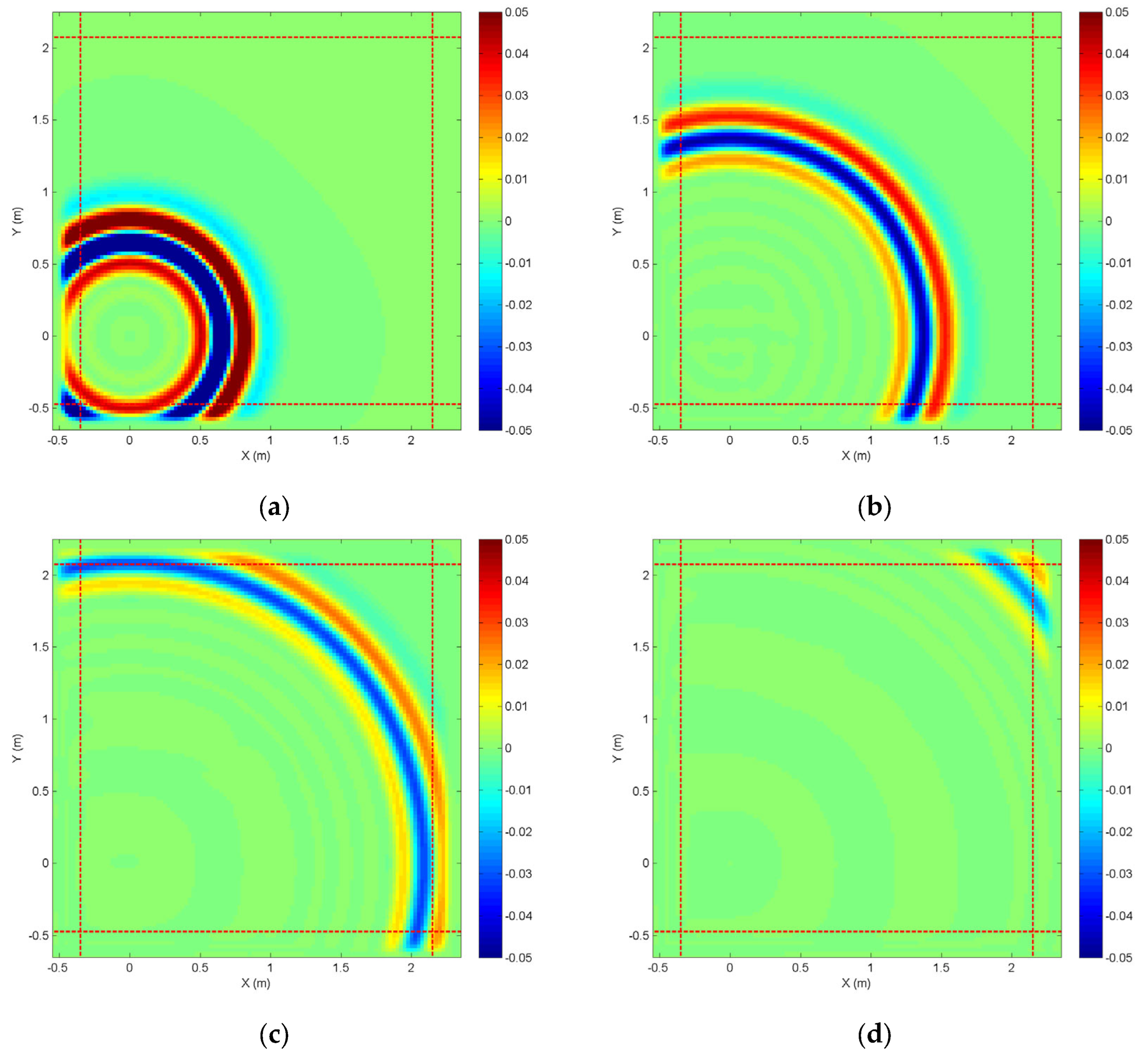
After the electromagnetic excitation with the transient pulse source from Equation (27), we can capture the diffusion at the plane Z = 0 m, as reflected in Figure 2, where the range outside the dashed line belongs to the PML region, and those color bars are the same and limited in [–0.05, 0.05] V/m.
As obviously seen in Figure 2a, those electromagnetic waves have propagated and penetrated into the lower-left PML regions when the iterative time step nt = 100, and no distinct reflection is found. Afterward in Figure 2b, those lower-left electromagnetic waves have all been absorbed and the only upper-right waves are still propagating. According to the deduction from the 3D view, no reflection occurred in the cross-section Z = 0 m is influenced by the wave propagation from the bottom PML region; therefore, the smooth circular-arc-shaped electromagnetic diffusion can be still maintained. When the time step nt = 200 in FDTD iteration, it can be seen that the electromagnetic diffusion starts to knock against upper-right PML regions in Figure 2c. Eventually, those waves in the whole FDTD domain are fully attenuated after time step nt = 250, as observed in Figure 2d.
In the common research, the frequency-domain results can be obtained by adopting the Fourier transform to the time-domain data from FDTD experiments. Dynamic electromagnetic data with all executing time steps in the cross-section Z = 0 m, 1 m, 2 m are processed by means of the Fourier transform. The specific expression can be defined as
X ( f ) = Δ t n = 1 N s t e p x ( n Δ t ) exp ( j ω   n Δ t )
To further verify that the outgoing electromagnetic waves have been fully absorbed when the time step nt = 4000, we select the maximum frequency of fmax = 1 GHz for achieving the data in the frequency domain, where in the cross-section Z = 0 m, 1 m, 2 m propagation profiles as shown in Figure 3. As can be clearly observed in Figure 3, the concentric circles are preserved under the same color bar as a limited condition, and the dash line outside belongs to those CFS-PML region to absorb the frequency-domain waves. No distortion from those concentric circles happens closest to the cross-section Z = 0 m and 2 m of top and bottom ends before the CFS-PML regions, which can indicate the highly effective absorption for the sinusoidal waves in the frequency domain.

4. Numerical Examples for Electromagnetic Scattering

To further validate the electromagnetic scattering for the Z-FDTD method, we choose the highly accurate commercial software COMSOL as an effective means to carry out the time-domain biaxial-anisotropic comparison with our proposal. COMSOL is numerical software based on the finite element method, which aims to solve the simulation of electromagnetic problems. The electromagnetic Gaussian pulse is employed as the input waveform and can be defined as
g ( t ) = exp [ ( t t 0 τ ) 2 ]
where the time-delay value, time constant and maximum frequency are, respectively,
t 0 = 4.5 τ , τ = 2.3 π   f max , f max = 1.5   GHz
Due to the fact that we cannot directly derive the electromagnetic pulse in COMSOL, the external data can be imported into the COMSOL software by numerical interpolation so that the corresponding comparison is performed in the same conditions with the same input excitation.

4.1. Single Brick with Biaxial Anisotropy

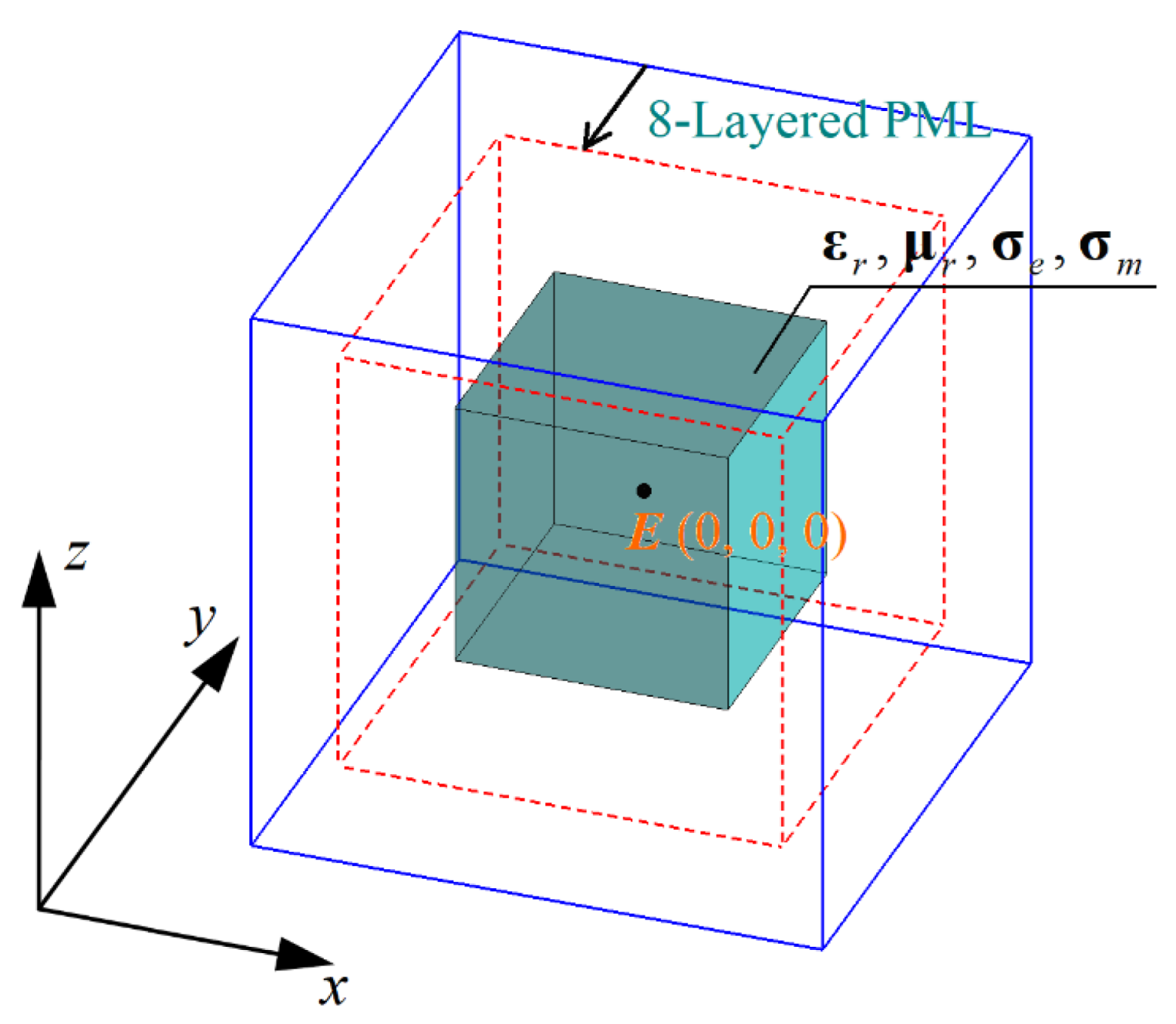
As illustrated in Figure 4, a single brick with biaxial anisotropy is placed at the center of the 3D region; its spatial size is 0.16 m × 0.16 m × 0.16 m, and its constitutive parameters are, respectively, defined as
ε r = diag ( 4 ,   3 ,   2 ) , μ r = diag ( 2 ,   3 ,   4 ) , σ e = diag ( 0.03 ,   0.09 ,   0.5 ) , σ m = diag ( 3000 ,   9000 ,   1000 ) .
The CFS-PML proposed in Section 2 is adopted to truncate the 3D Z-FDTD domain, which is 69 × 69 × 69 in the specific grids and Δx = Δy = Δz = 0.005 m in the spatial cell. Moreover, the parameters of plane waves are set as Eθ = 1, Eφ = 0, θinc = 45°, φinc = 30°. By applying the Gaussian pulse Equation (29) for the transient field, electric fields (Ex, Ey, Ez) from the single brick with biaxial anisotropy can be easily obtained within 10 ns at the center of the FDTD domain, as displayed in Figure 5. Meanwhile, it can be seen in Figure 5 that their results are almost consistent, and those norm errors between them are, respectively, 0.0068, 0.0039, and 0.0017. Furthermore, as shown in Figure 6, the RCS results can be obtained at the frequency point f = 1 GHz when transient fields cover the whole computational region. Finally, the good agreements from numerical results can be, respectively, achieved in the cross-section xOy, yOz, and zOx.
The CFS-PML proposed in Section 2 is adopted to truncate the 3D Z-FDTD domain, which is 69 × 69 × 69 in the specific grids and Δx = Δy = Δz = 0.005 m in the spatial cell. Moreover, the parameters of plane waves are set as Eθ = 1, Eφ = 0, θinc = 45°, φinc = 30°. By applying the Gaussian pulse Equation (29) for the transient field, electric fields (Ex, Ey, Ez) from the single brick with biaxial anisotropy can be easily obtained within 10 ns at the center of the FDTD domain, as displayed in Figure 5. Meanwhile, it can be seen in Figure 5 that their results are almost consistent, and those norm errors between them are, respectively, 0.0068, 0.0039, and 0.0017. Furthermore, as shown in Figure 6, the RCS results can be obtained at the frequency point f = 1 GHz when transient fields cover the whole computational region. Finally, good agreements from the numerical results can be, respectively, achieved in the cross-section xOy, yOz, and zOx. The mesh from COMSOL is tetrahedral in three-dimensional space, but the Z-FDTD method still follows Yee’s cell for subdivision. The far-field scattering must compute the envelope of the whole object to extrapolate the near-field to the far-field; hence, there will be small errors between the two methods within a reasonable range.

4.2. Multi-Layered Sphere with Different Biaxial Anisotropies

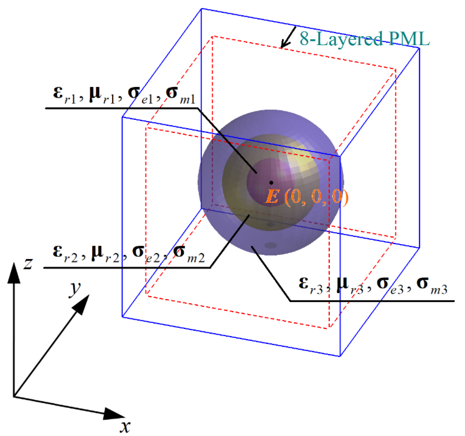
To further validate a more complicated model, we construct the multi-layer sphere with three different biaxial anisotropies to proceed with our verification. As shown in Figure 7, designed as a three-layered sphere, the model can be given by constitutive parameters as follows:
Medium 1
ε r 1 = diag ( 3.3 ,   2.1 ,   2.6 ) , μ r 1 = diag ( 1.2 ,   1.8 ,   3.5 ) , σ e 1 = diag ( 0.12 ,   0.29 ,   0.18 ) , σ m 1 = diag ( 4200 ,   9600 ,   5300 )
Medium 2
ε r 2 = diag ( 1.8 ,   3.9 ,   1.5 ) , μ r 2 = diag ( 3.6 ,   1.1 ,   3.3 ) , σ e 2 = diag ( 0.43 ,   0.08 ,   0.25 ) , σ m 2 = diag ( 8600 ,   1200 ,   2900 )
Medium 3
ε r 3 = diag ( 2.5 ,   1.3 ,   3.8 ) , μ r 3 = diag ( 2.9 ,   3.5 ,   2.3 ) , σ e 3 = diag ( 0.28 ,   0.61 ,   0.34 ) , σ m 3 = diag ( 6700 ,   4500 ,   3800 )
The center positions of multi-layer spheres are fixed in (0, 0, 0), and radii of these spheres from the external layer to the internal layer are, respectively, 0.15 m, 0.10 m, and 0.05 m. The Z-FDTD domain is 97 × 97 × 97 in size and Δx = Δy = Δz = 0.005 m in the spatial cell; meanwhile, eight-layered PML are applied to the truncation region. Moreover, the parameters of plane waves are denoted as Eθ = 1, Eφ = 3, θinc = 70°, φinc = 55°. By Gaussian pulse Equation (29) in the transient fields, the electric field observation point (Ex, Ey, Ez) is captured within the propagating time of 12 ns, as shown in Figure 8. At that time, we can find in Figure 8 that their results are almost consistent with, respectively, 0.006, 0.0042, and 0.0053 in those norm errors. As reflected in Figure 9, the RCS results can be recorded at the frequency point f = 1 GHz when transient fields cover the whole Z-FDTD region. Finally, good agreements of those numerical results in the xOy, yOz, and zOx can be implemented.

5. Conclusions

In our work, we successfully applied the Z-transform technique to the 3D FDTD method for the electromagnetic scattering with biaxial anisotropy. The considered biaxial anisotropy belongs to general electromagnetic media, which include the dielectric tensor, permeability tensor, conductivity tensor, and magnetic-loss tensor. For the Z-FDTD method, the CFS-PML scheme was chosen and succeeded in capturing the time-varying process and implementing single-frequency distribution after the Fourier transform. To our knowledge, this is the first time Z-transform-based biaxial anisotropy has been used to solve an electromagnetic problem with a constitutive relationship. To verify the Z-FDTD method, we execute two different kinds of 3D biaxial anisotropic models, containing a single brick and the multi-layer spheres, and hence obtain time-domain data and single-frequency RCS results. In brief, our proposed method can bring about good agreements with reasonable accuracy using the COMSOL software.

Author Contributions

Conceptualization, N.F. and Y.Z.; methodology, N.F., J.Z. and Y.Z.; formal analysis, Y.Z., G.X. and Z.H.; writing—original draft preparation, N.F., G.X. and J.Z.; writing—review and editing, N.F., Y.Z., J.Z., Z.H. and L.Y. All authors have read and agreed to the published version of the manuscript.

Funding

This research is funded by the National Natural Science Foundation of China under grants 61901274, 62101333, and U20A20164; Natural Science Foundation of Guangdong Province under grant 2020A1515011475; Shenzhen Science and Technology Innovation Committee under grant JCYJ20190808141818890; University Stability Support Project of Shenzhen under grant 20200813152750001; and Open Fund of State Key Laboratory of Applied Optics under grant SKLAO2020001A06.

Data Availability Statement

Not applicable.

Conflicts of Interest

The authors declare no conflict of interest.

References

  1. Taflove, A.; Hagness, S.C. Computational Electrodynamics: The Finite-Difference Time-Domain Method; Artech House: Boston, MA, USA; London, UK, 1998. [Google Scholar]
  2. Elsherbeni, A.Z.; Demir, V. The Finite-Difference Time-Domain Method for Electromagnetics with MATLAB Simulations; Scitech Publishing: Raleigh, NC, USA, 2015. [Google Scholar]
  3. Sullivan, D.M. Frequency-dependent FDTD methods using Z transforms. IEEE Trans. Antennas Propagat. 1992, 40, 1223–1230. [Google Scholar] [CrossRef]
  4. Sullivan, D.M. Nonlinear FDTD formulations using Z transforms. IEEE Trans. Micro. Theory Tech. 1995, 43, 676–682. [Google Scholar] [CrossRef]
  5. Sullivan, D.M. Z-transform theory and the FDTD method. IEEE Trans. Antennas Propagat. 1996, 44, 28–34. [Google Scholar] [CrossRef]
  6. Weedon, W.H.; Rappaport, C.M. A general method for FDTD modeling of wave propagation in arbitrary frequency-dispersive media. IEEE Trans. Antennas Propagat. 1997, 45, 401–410. [Google Scholar] [CrossRef]
  7. Pereda, J.A.; Vegas, A.; Prieto, A. FDTD modeling of wave propagation in dispersive media by using the Mobius transformation technique. IEEE Trans. Micro. Theory Tech. 2002, 50, 1689–1695. [Google Scholar] [CrossRef]
  8. Yan, M.; Shao, K.R.; Hu, X.W.; Guo, Y.; Zhu, J.; Lavers, J.D. Z-transform-based FDTD analysis of perfectly conducting cylinder covered with unmagnetized plasma. IEEE Trans. Magnet. 2007, 43, 2968–2970. [Google Scholar] [CrossRef] [Green Version]
  9. Demir, V.; Elsherbeni, A.Z.; Arvas, E. FDTD formulation for dispersive chiral media using the Z transform method. IEEE Trans. Antennas Propagat. 2005, 53, 3374–3384. [Google Scholar] [CrossRef]
  10. Nadobny, J.; Sullivan, D.; Wust, P. A general three-dimensional tensor FDTD-formulation for electrically inhomogeneous lossy media using the Z-transform. IEEE Trans. Antennas Propagat. 2008, 56, 1027–1040. [Google Scholar] [CrossRef]
  11. Nayyeri, V.; Soleimani, M.; Mohassel, J.R.; Dehmollaian, M. FDTD modeling of dispersive bianisotropic media using Z-transform method. IEEE Trans. Antennas Propagat. 2011, 59, 2268–2279. [Google Scholar] [CrossRef]
  12. Kastner, R. A multidimensional Z-transform evaluation of the discrete finite difference time domain Green’s function. IEEE Trans. Antennas Propagat. 2006, 54, 1215–1222. [Google Scholar] [CrossRef]
  13. Jeng, S.K. An analytical expression for 3-D dyadic FDTD-compatible Green’s function in infinite free space via Z-transform and partial difference operators. IEEE Trans. Antennas Propagat. 2011, 59, 1347–1355. [Google Scholar] [CrossRef]
  14. Abdijalilov, K.; Grebel, H. Z-transform theory and FDTD stability. IEEE Trans. Antennas Propagat. 2004, 52, 2950–2954. [Google Scholar] [CrossRef]
  15. Lin, Z.; Thylen, L. On the accuracy and stability of several widely used FDTD approaches for modeling Lorentz dielectrics. IEEE Trans. Antennas Propagat. 2009, 57, 3378–3381. [Google Scholar] [CrossRef]
  16. Heh, D.Y.; Tan, E.L. Corrected impulse invariance method in Z-transform theory for frequency-dependent FDTD methods. IEEE Trans. Antennas Propagat. 2009, 57, 2683–2690. [Google Scholar] [CrossRef]
  17. Penney, C.W.; Luebbers, R.J.; Schuster, J.W. Scattering from coated targets using a frequency-dependent, surface impedance boundary condition in FDTD. IEEE Trans. Antennas Propagat. 1996, 44, 434–443. [Google Scholar] [CrossRef]
  18. Feng, N.; Yue, Y.; Liu, Q.H. Direct Z-transform implementation of the CFS-PML based on memory-minimized method. IEEE Trans. Micro. Theory Tech. 2015, 63, 877–882. [Google Scholar] [CrossRef]
  19. Feng, N.; Wang, J.; Zhu, J.; Liang, Z.; Wang, G.P.; Joines, W.T. Switchable truncations between the 1st- and 2nd-order DZT-CFS-UPMLs for relevant FDTD problems. IEEE Trans. Antennas Propagat. 2020, 68, 360–365. [Google Scholar] [CrossRef]
  20. Giannopoulos, A. Higher-order convolution PML (CPML) for FDTD electromagnetic modeling. IEEE Trans. Antennas Propagat. 2020, 68, 6226–6231. [Google Scholar] [CrossRef]
  21. Wang, Z.; Guo, L.; Li, J. Analysis of echo characteristics of spatially inhomogeneous and time-varying plasma sheath. IEEE Trans. Plasma Sci. 2021, 49, 1804–1811. [Google Scholar] [CrossRef]
  22. Han, X.; Xu, H.; Chang, Y.; Lin, M.; Wei, X. Investigation on the parameters distribution and electromagnetic scattering of radome inductively coupled plasma. IEEE Trans. Antennas Propagat. 2021, 69, 8711–8721. [Google Scholar] [CrossRef]
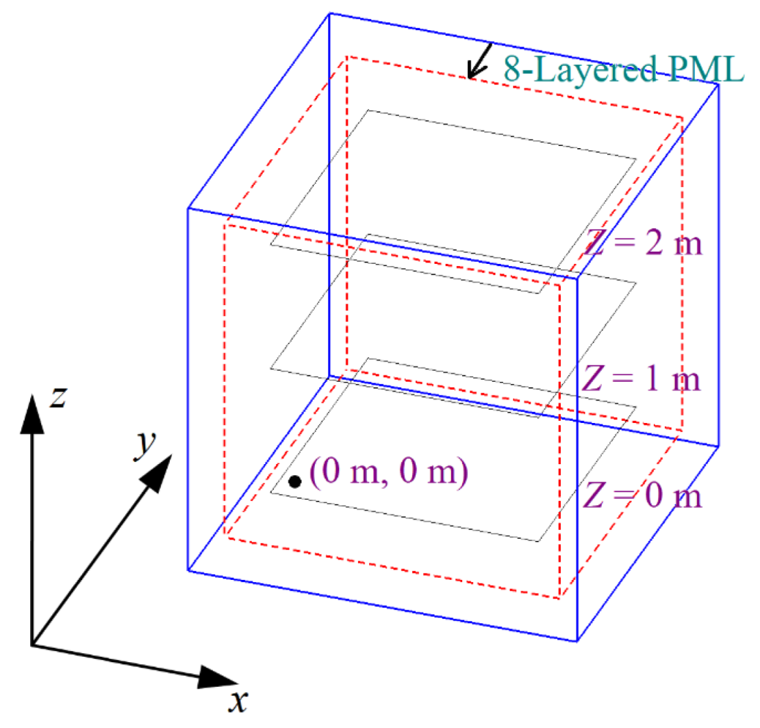
Figure 1. Diagram of 3D electric dipole radiation. the coordinate (0 m, 0 m, 0 m) is located at the near corner portions in the 3D space, the cross-sections Z = 0 m, 1 m, 2 m are, respectively, the observation planes during the electromagnetic transient process.
Remotesensing 14 02397 g001
Figure 2. Dynamic process in the Z-FDTD iteration: (a) nt = 100; (b) nt = 150; (c) nt = 200; (d) nt = 250.
Remotesensing 14 02397 g002
Figure 3. Process from the time- to the frequency-domain by the Fourier transform, and the cross-section diagram at the frequency point f = 1 GHz when nt = 4000: (a) Z = 0 m, (b) Z = 1 m, (c) Z = 2 m.
Remotesensing 14 02397 g003
Figure 4. Three-dimensional single brick with biaxial anisotropy, where E(0, 0, 0) is denoted as the observation point in time domain.
Remotesensing 14 02397 g004
Figure 5. Time-domain results of observation point E(0, 0, 0) when waves propagate through the single brick between 0 and 10 ns: (a) Ex; (b) Ey; (c) Ez.
Remotesensing 14 02397 g005
Figure 6. RCS results of single brick at the frequency point f = 1 GHz: (a) xOy plane; (b) yOz plane; (c) zOx plane.
Remotesensing 14 02397 g006
Figure 7. Three-dimensional multi-layer spheres with biaxial anisotropy where E(0, 0, 0) is denoted as the observation point in time domain.
Remotesensing 14 02397 g007
Figure 8. Time-domain results of observation point E(0, 0, 0) when waves propagate through the multi-layer spheres: (a) Ex; (b) Ey; (c) Ez.
Remotesensing 14 02397 g008
Figure 9. RCS results of multilayer spheres at the frequency point f = 1 GHz: (a) xOy plane; (b) yOz plane; (c) zOx plane.
Remotesensing 14 02397 g009
Publisher’s Note: MDPI stays neutral with regard to jurisdictional claims in published maps and institutional affiliations.