
Robust and Efficient Trajectory Replanning Based on Guiding Path for Quadrotor Fast Autonomous Flight


Abstract
1. Introduction
- This paper designs an improved A* and path pruning method to generate a safe guiding path, which can be used to perceive the surrounding environment and guide the method to search and optimize the path.
- Aiming to reduce the spatial information loss caused by discrete control space and improve the quality of the initial path, this paper proposes a guided kinodynamic path searching (GKPS) method based on the guiding path, which not only retains the advantages of the kinodynamic path searching but also improves the safety with the help of the guiding path.
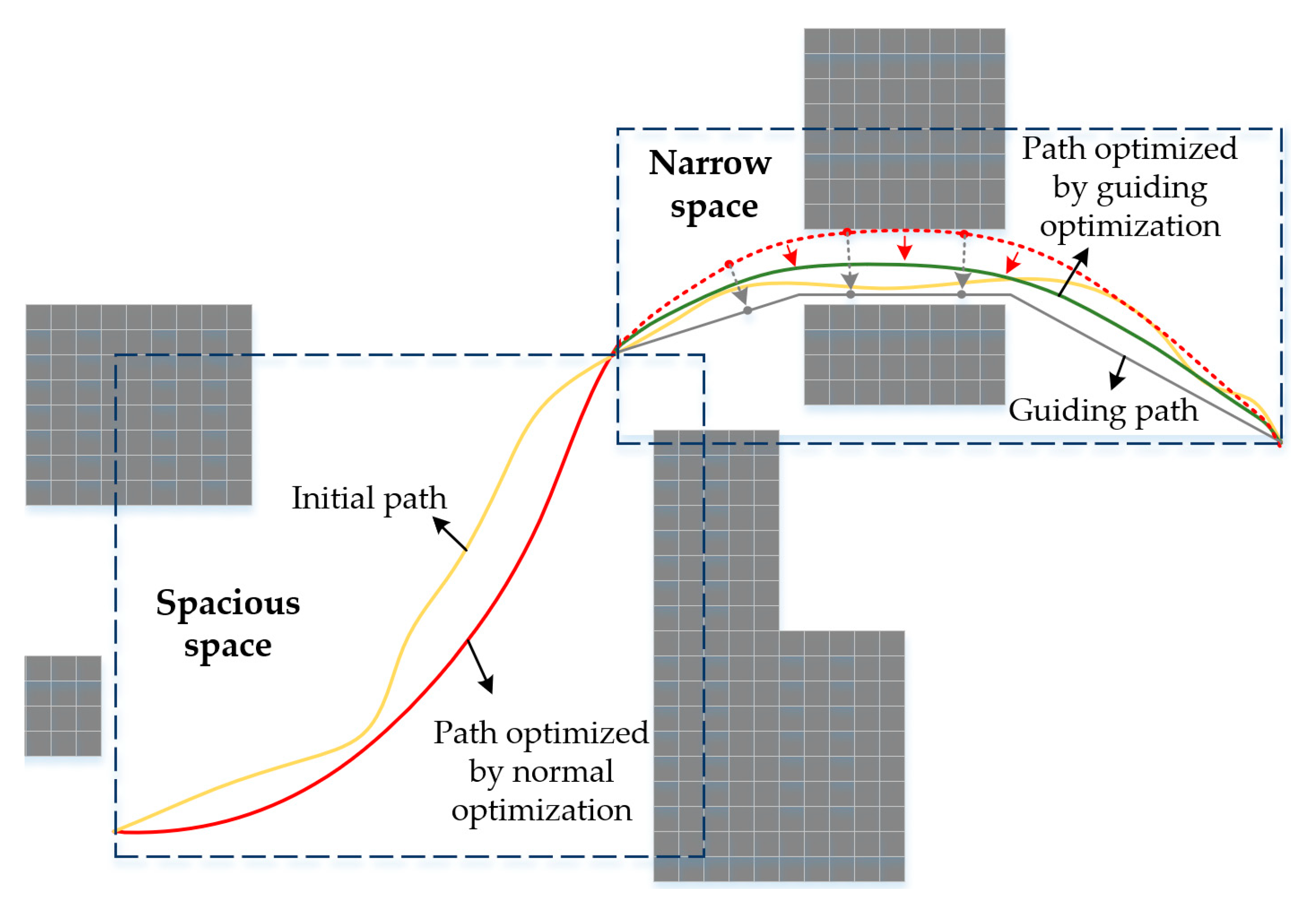
- Aiming to improve the performance of path optimization in the cluttered environment, this paper designs an adaptive optimization function with two modes. According to the perception result of the guiding path towards the narrow space, the function adaptively selects the optimization mode, which improves the optimization quality in narrow spaces.
- Extensive simulation experiments are carried out with three state-of-the-art methods, which validates the effectiveness of the proposed method. We also compare the proposed method with the method that only uses GKPS, which verifies the efficiency of the optimization part.
2. Methods
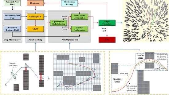
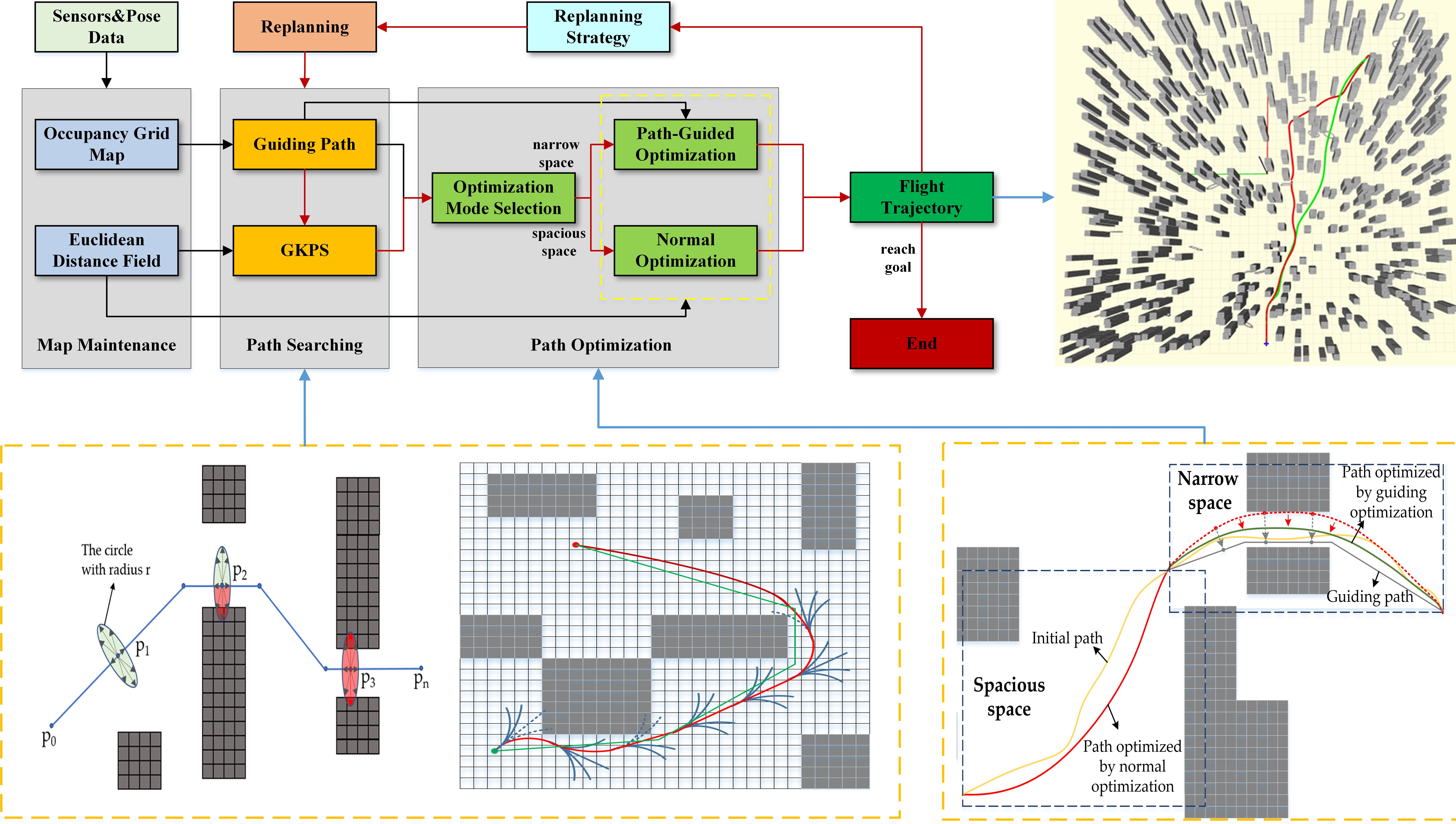
- Map maintenance: this algorithm maintains the occupancy grid map and Euclidean distance field map (EDF). The occupancy grid map is updated in real-time using the information obtained by sensors during flight, and the obstacle information is recorded to provide services for the generation of a guiding path. The Euclidean distance field is only maintained by using the information obtained from current sensors to serve path planning and optimization.
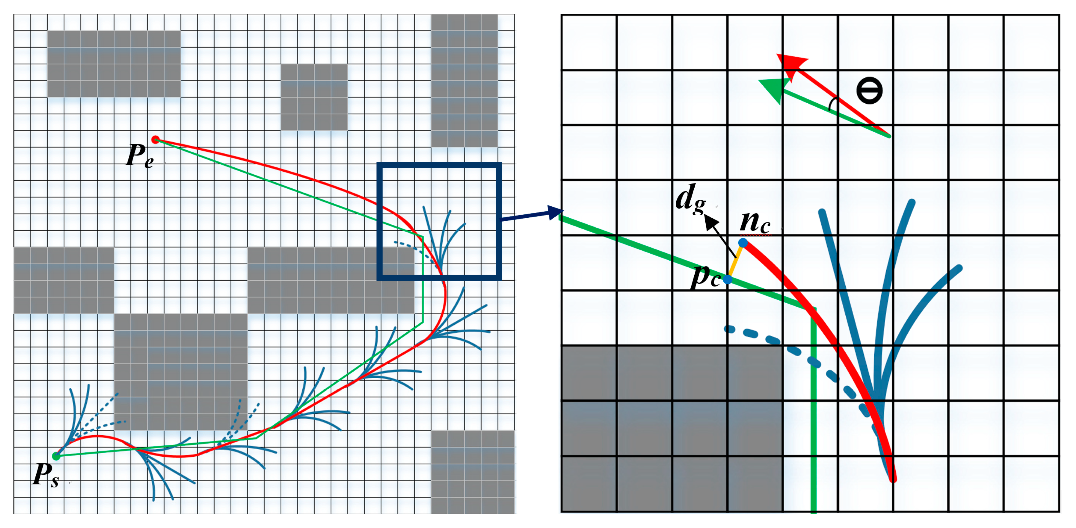
- Path searching: At first, we use occupancy grid map and pose data to quickly generate a collision-free and passable geometric guiding path. Then, using the obstacle information maintained by the occupancy grid map, we perceive the surrounding space that the guiding path passes through and judge whether it passes through a narrow space. Next, under the help of the guiding path, the guided kinodynamic path searching (GKPS) method is designed to quickly generate a dynamically feasible, safe, and low-cost initial path.
- Path optimization: We design an adaptive optimization function with two optimization modes, normal optimization (NO) and path-guided optimization (PGO). According to the perception results of the guiding path to the narrow space, the path optimization mode is selected adaptively to optimize the initial path. Finally, a smooth, safe, and feasible path that meets the autonomous and fast flight of UAVs is generated.
2.1. Map Maintenance
2.2. Path Searching
2.2.1. Guiding Path Generation
- A.
- Improved A*
| Algorithm 1: Improved A* | |
| Input: Current position and velocity , target position Output: A geometric path PA* from the current position to the target position 1 Initialize(); 2 While !P.empty() do 3 nc P.pop(), C.insert(nc); 4 if ReachGoal(nc) || ReachEdge(nc) then 5 return RetrievePath(); 6 expendNodes Expend(nc); 7 for ni in nodes do 8 if !C.contain(ni) ^ CheckFeasible() then 9 gtemp ni.gc + EdgeCost(ni); 10 if !P.contain(ni) then 11 P.add(ni); 12 else if gtemp >= ni.gc then 13 continue; 14 end if 15 ni.parent nc, ni.gc gtemp; 16 ni.fcni.gc + Heuristic(ni); 17 end if 18 end 19 end while | |
- B.
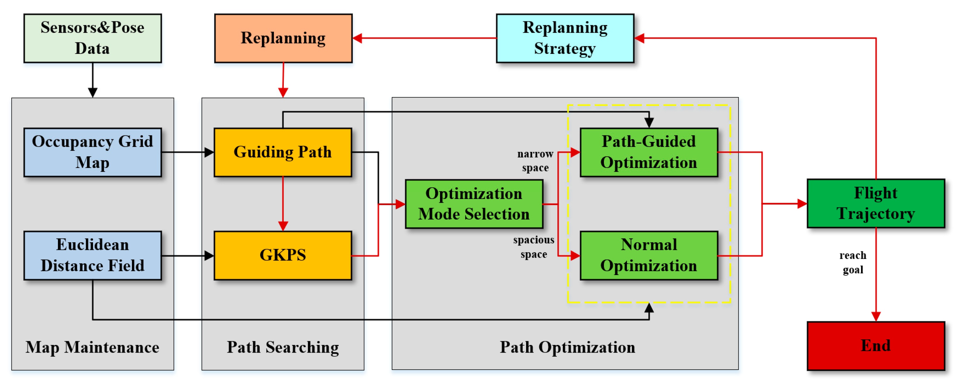
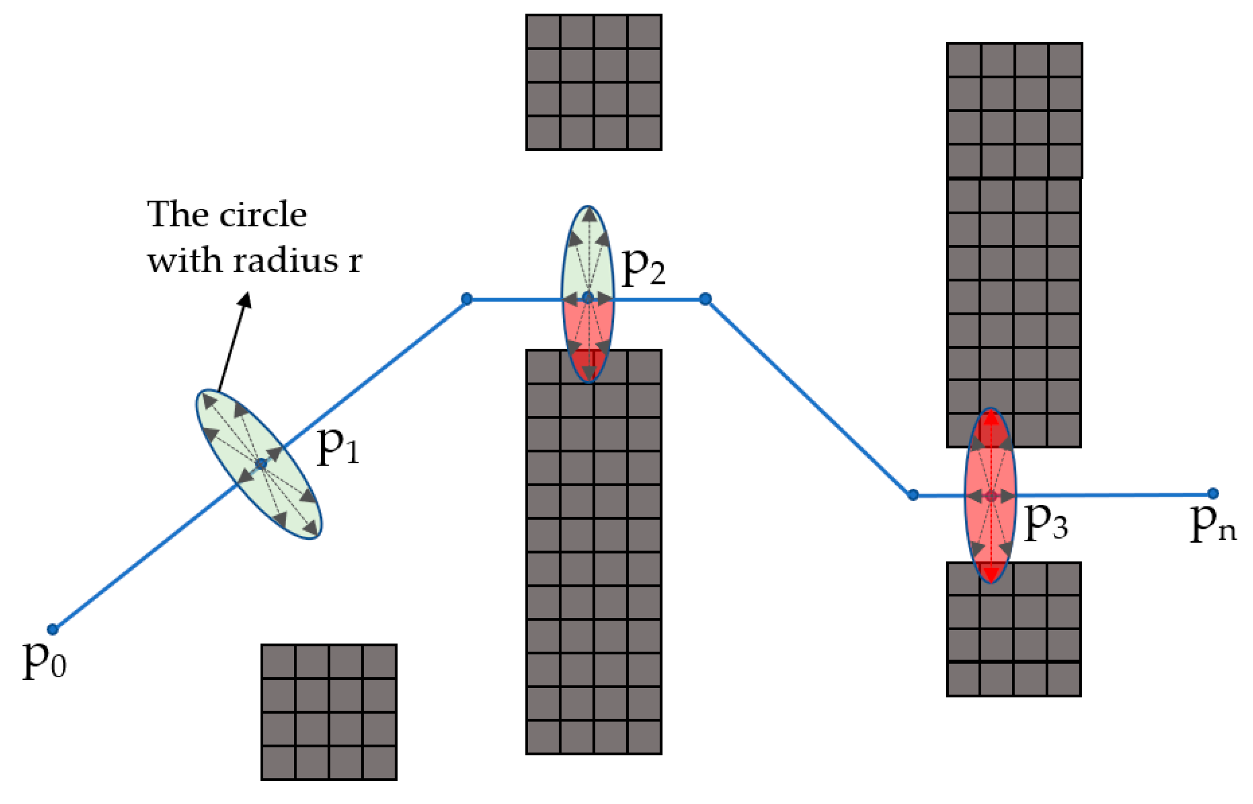
- Path Pruning
| Algorithm 2: Pruning PA* to Pnew | |
| Input: the path PA* generated by Algorithm 1 Output: a shortcut path Pnew for PA* 1 Pnew PA*.front() 2 foreach pA* PA* do 3 lA* Line(Pnew.back(), pA*) 4 if !LineVisible(lA*) then 5 pb BlockVoxel(pA*) 6 pn PushAwayObs(pb, lA*) 7 Pnew.push_back(pn) 8 end if 9 end 10 Pnew.push_back(pA*.back()) 11 return Pnew | |
2.2.2. Scene Perception
2.2.3. Guided Kinodynamic Path Searching
- A.
- Primitives Generation
- B.
- Actual Cost
- C.
- Adaptive Heuristic Function
- D.
- Direct Expansion Strategy
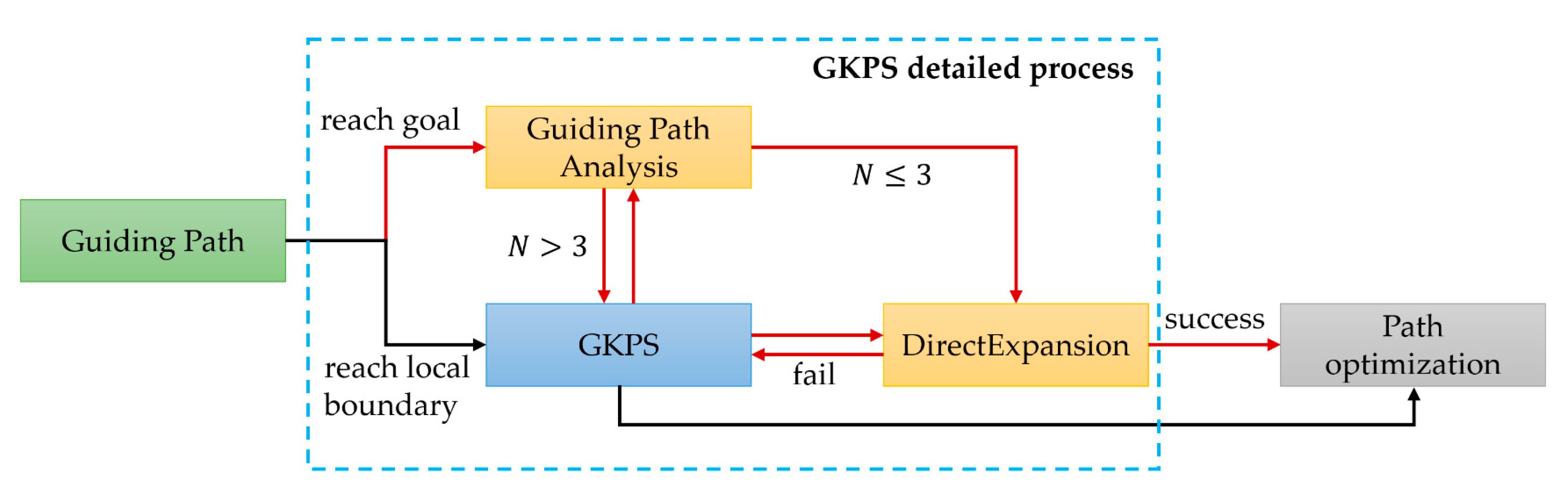
- Judge whether the guiding path reaches the endpoint. If it reaches the endpoint, start the expansion strategy and carry out the next step (red line). Otherwise, carry out the normal GKPS process (black line);
- Analyze the guiding path. If the number of remaining nodes N of the guiding path is not more than three, then it is considered that the road environment is relatively spacious, and directly carries out step 4. Otherwise, carry out the next step;
- Carry out the normal GKPS, but after each node expansion, execute step 2;
- Direct expansion process, which generates an accurate path from the current node to target point by using the same approach in [39]. If the route is safe and reliable, stop the path searching and enter the path optimization part, otherwise continue to step 3.
2.3. Adaptive Trajectory Optimization
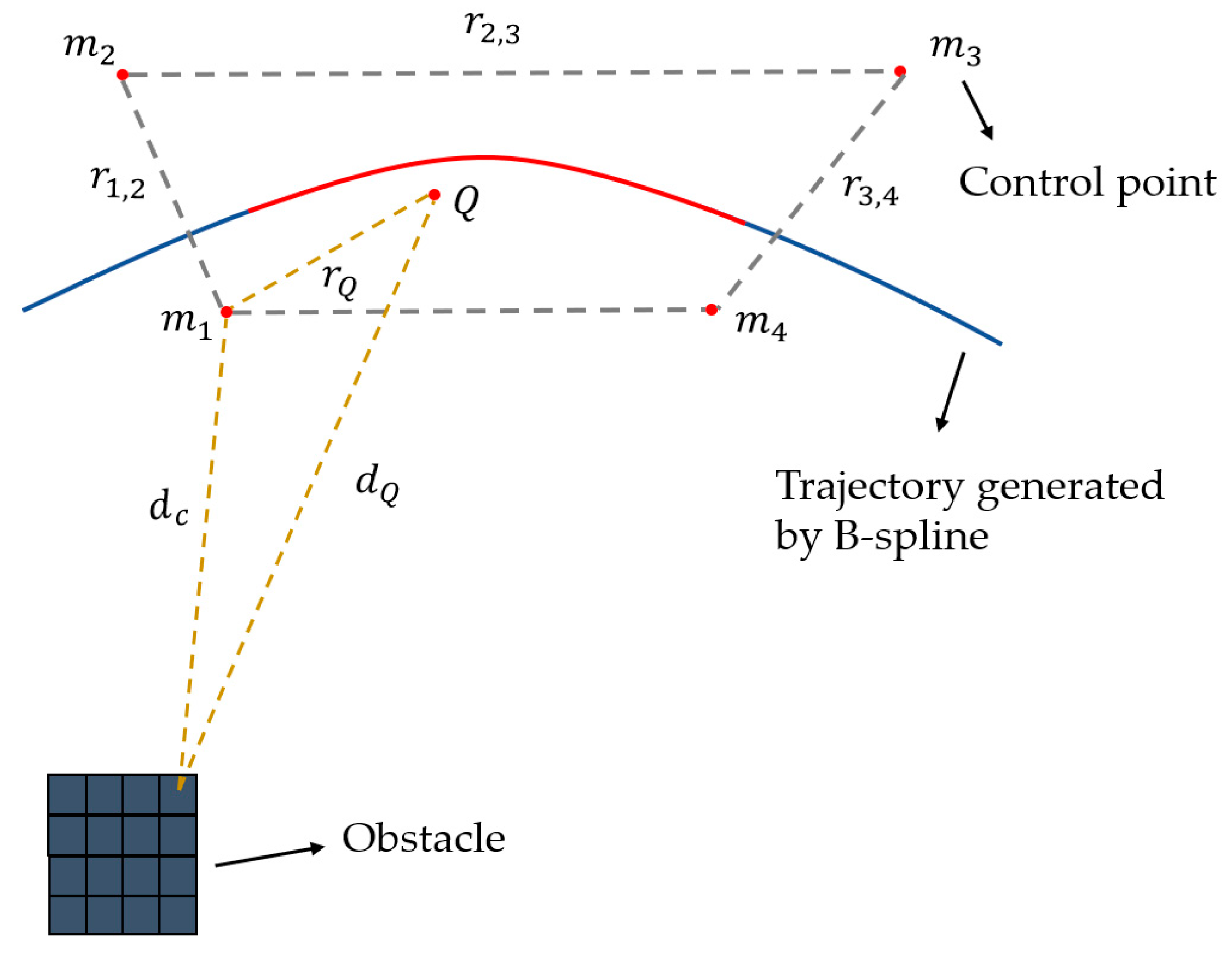
2.3.1. Uniform B-Splines
2.3.2. Adaptive Cost Function
3. Experimental Results
3.1. Experimental Details
3.2. Benchmark Comparisons
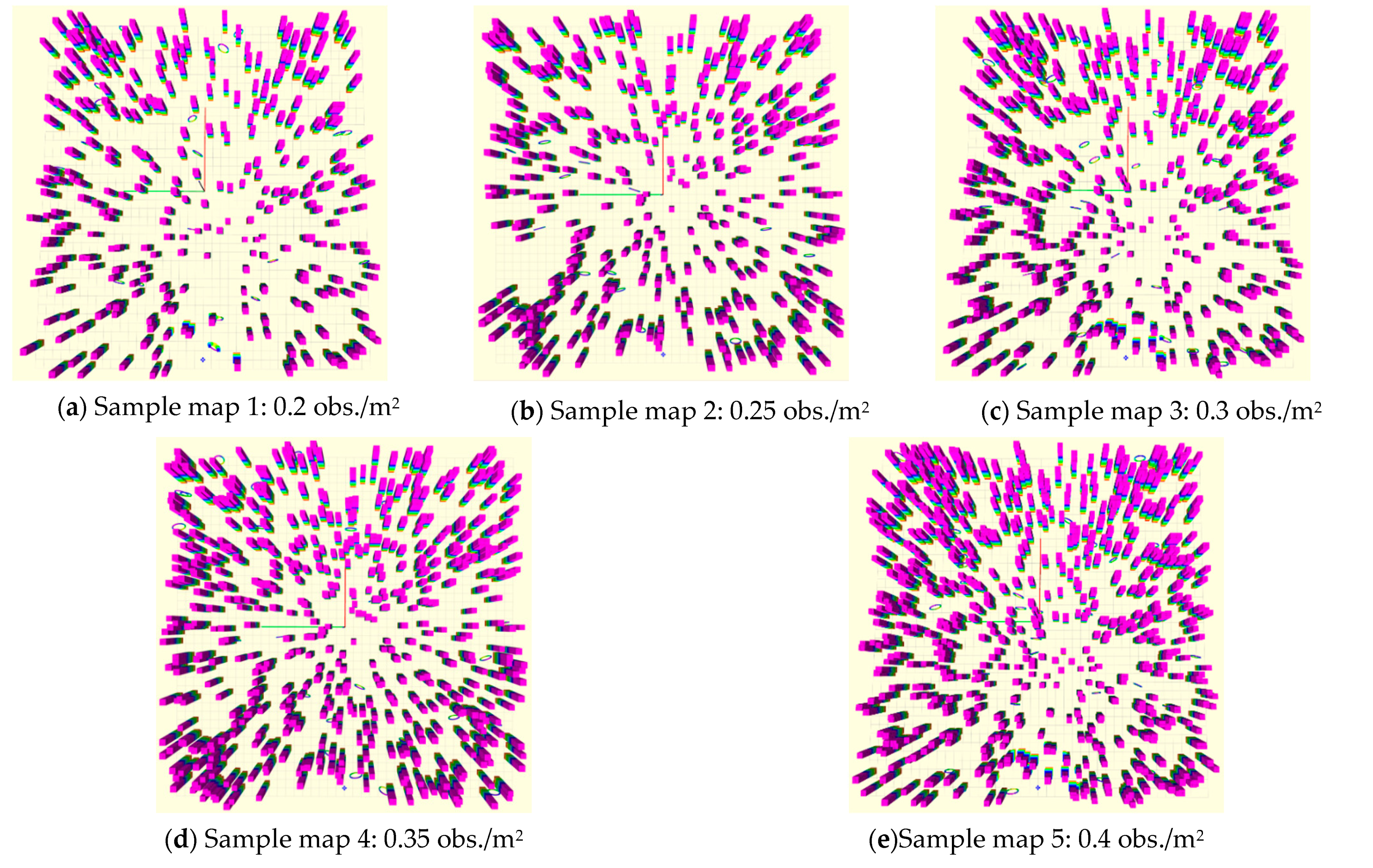
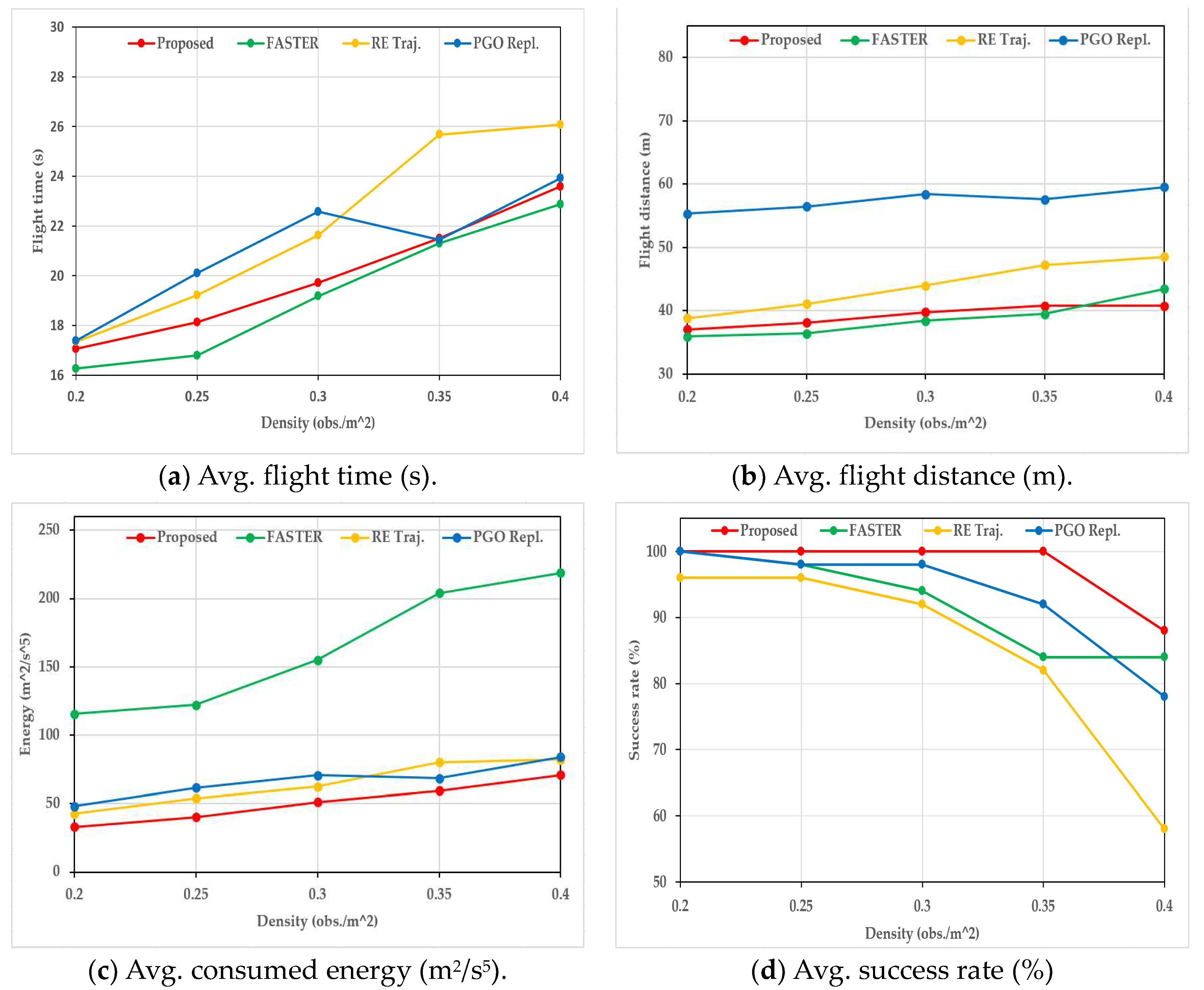
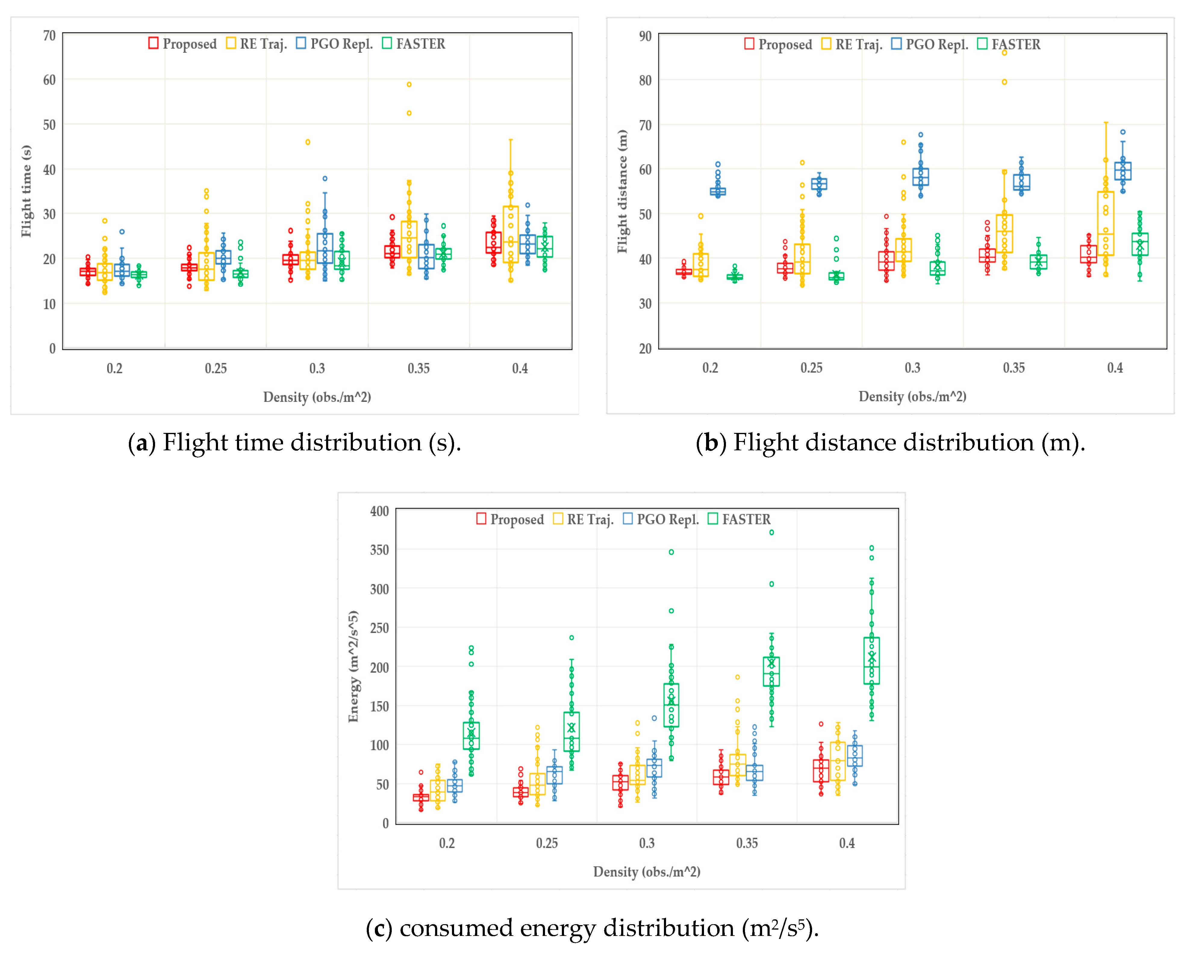
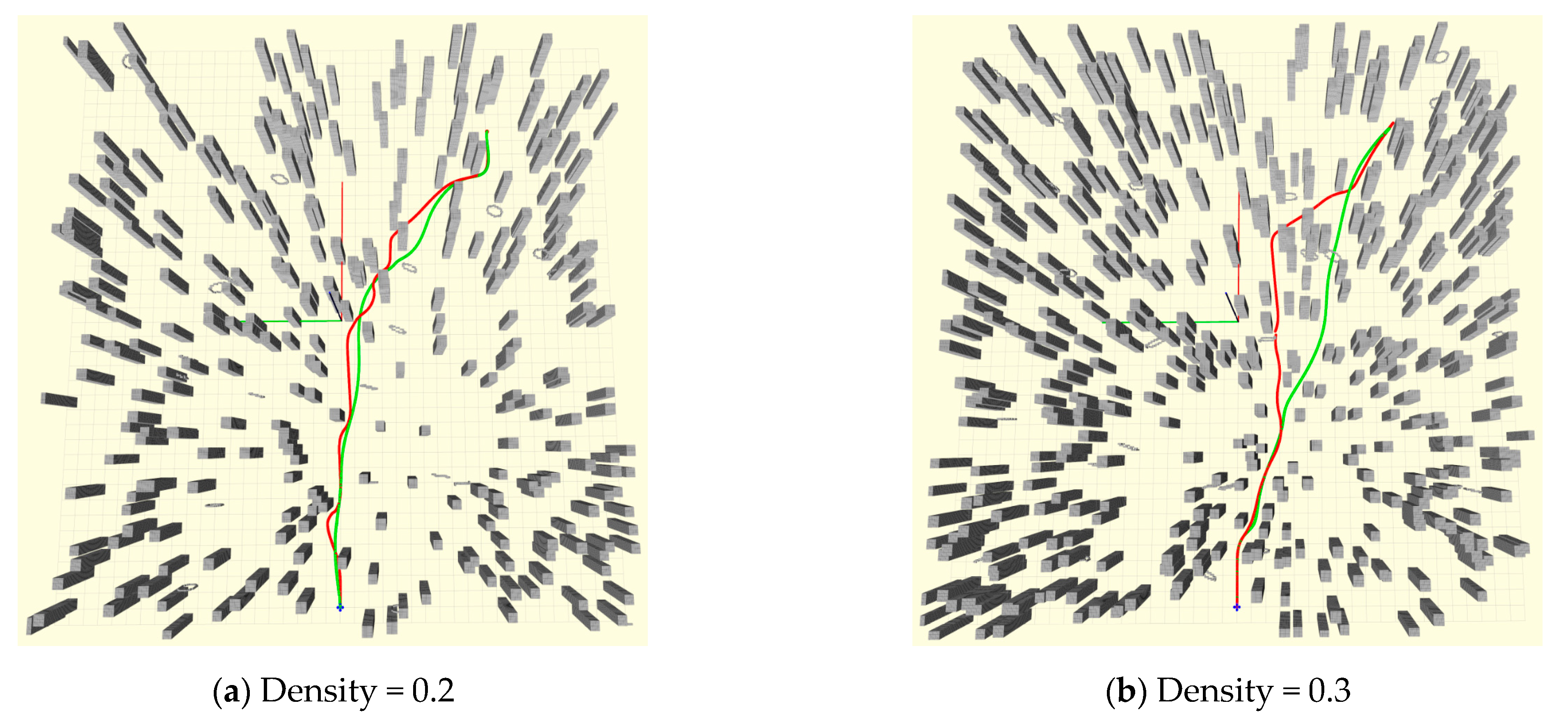
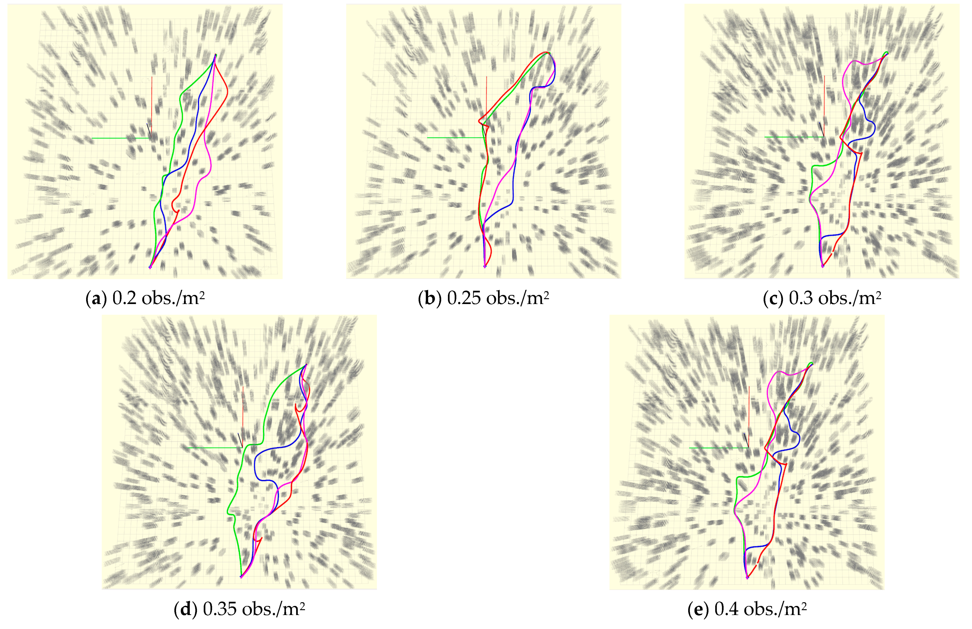
3.2.1. Efficiency Analysis under Different Obstacle Densities
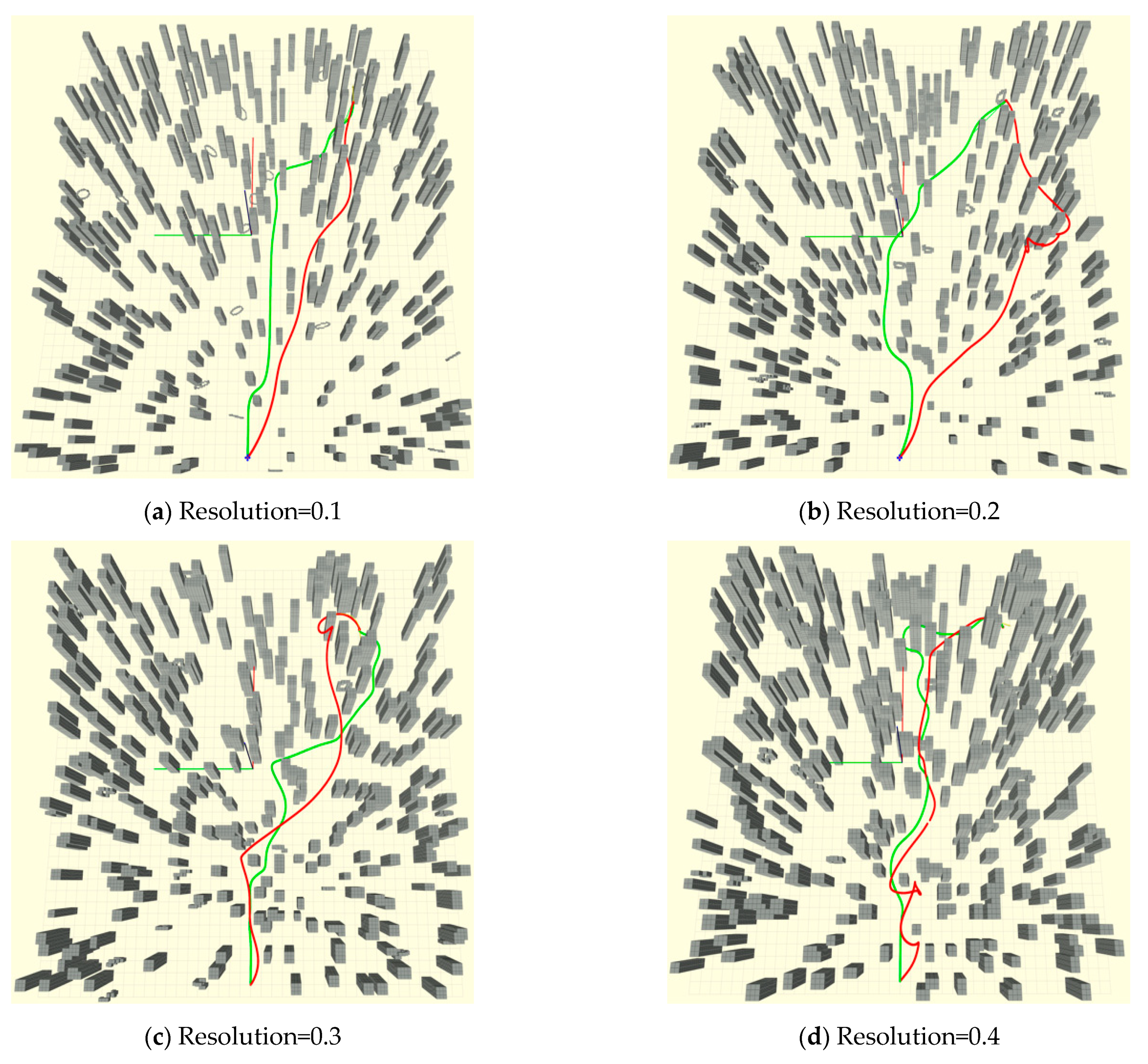
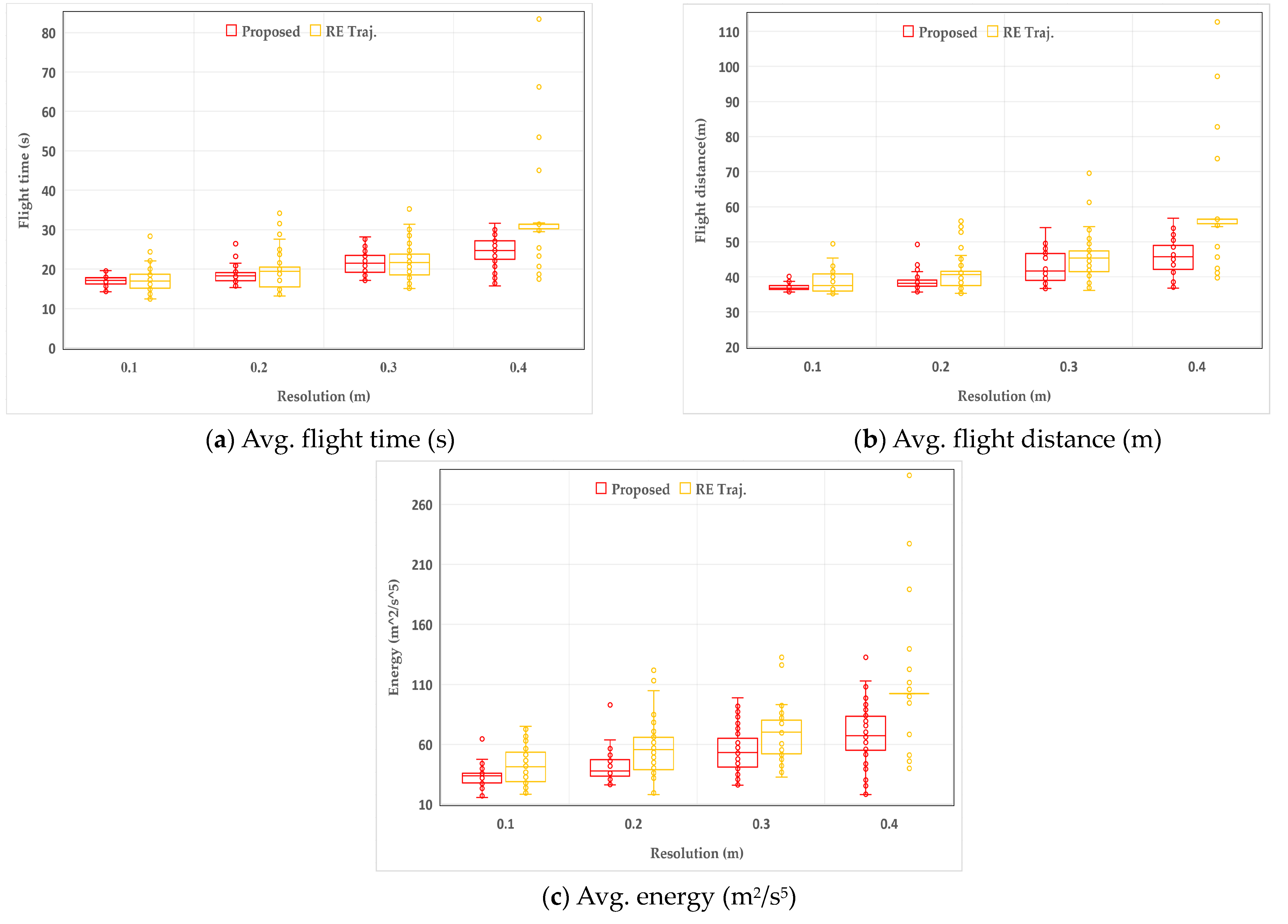
3.2.2. Efficiency Analysis under Different Resolution
3.2.3. Comparison of Performance before and after Optimization
4. Discussion
5. Conclusions
Author Contributions
Funding
Conflicts of Interest
References
- Mohd Noor, N.; Abdullah, A.; Hashim, M. Remote sensing UAV/drones and its applications for urban areas: A review. IOP Conf. Ser. Earth Environ. Sci. 2018, 169, 12003. [Google Scholar] [CrossRef]
- Koch, T.; Körner, M.; Fraundorfer, F. Automatic and Semantically-Aware 3D UAV Flight Planning for Image-Based 3D Reconstruction. Remote Sens. 2019, 11, 1550. [Google Scholar] [CrossRef]
- Dai, J.; Yan, L.; Liu, H.; Chen, C.; Huo, L. An Offline Coarse-To-Fine Precision Optimization Algorithm for 3D Laser SLAM Point Cloud. Remote Sens. 2019, 11, 2352. [Google Scholar] [CrossRef]
- Chen, S.W.; Nardari, G.V.; Lee, E.S.; Qu, C.; Liu, X.; Romero, R.A.F.; Kumar, V. SLOAM: Semantic Lidar Odometry and Mapping for Forest Inventory. IEEE Robot. Autom. Lett. 2020, 5, 612–619. [Google Scholar] [CrossRef]
- Ouyang, J.; Simonson, S.L.; Zhang, Y.; Zhuang, C.; Wang, J.; Chen, Z.; Qiao, Y.; Duan, Y.; Zheng, S. Using UAV technology for basic data collection of Firmiana danxiaensis HH Hsue & HS Kiu, JS (Malvaceae), an important, nationally protected wild plant in Zhanglao Peak, Danxiashan Mountain, South China. IOP Conf. Ser. Earth Environ. Sci. 2020, 467, 12130. [Google Scholar]
- Battulwar, R.; Winkelmaier, G.; Valencia, J.; Naghadehi, M.Z.; Peik, B.; Abbasi, B.; Parvin, B.; Sattarvand, J. A Practical Methodology for Generating High-Resolution 3D Models of Open-Pit Slopes Using UAVs: Flight Path Planning and Optimization. Remote Sens. 2020, 12, 2283. [Google Scholar] [CrossRef]
- Erdelj, M.; Natalizio, E.; Chowdhury, K.R.; Akyildiz, I.F. Help from the sky: Leveraging UAVs for disaster management. IEEE Pervas. Comput. 2017, 16, 24–32. [Google Scholar] [CrossRef]
- Sandino, J.; Vanegas, F.; Maire, F.; Caccetta, P.; Sanderson, C.; Gonzalez, F. UAV Framework for Autonomous Onboard Navigation and People/Object Detection in Cluttered Indoor Environments. Remote Sens. 2020, 12, 3386. [Google Scholar] [CrossRef]
- Pajares, G. Overview and current status of remote sensing applications based on unmanned aerial vehicles (UAVs). Photogramm. Eng. Remote Sens. 2015, 81, 281–330. [Google Scholar] [CrossRef]
- Ramesh, P.S.; Jeyan, J.M.L. Comparative analysis of the impact of operating parameters on military and civil applications of mini unmanned aerial vehicle (UAV). In AIP Conference Proceedings; AIP Publishing LLC: Chennai, India, 2020; Volume 2311, p. 0034. [Google Scholar]
- Xu, B.; Chen, Y.; Zhang, S.; Wang, J. Improved Point–Line Visual–Inertial Odometry System Using Helmert Variance Component Estimation. Remote Sens. 2020, 12, 2901. [Google Scholar] [CrossRef]
- Chen, Y.; Yan, L.; Xu, B.; Liu, Y. Multi-Stage Matching Approach for Mobile Platform Visual Imagery. IEEE Access 2019, 7, 160523–160535. [Google Scholar] [CrossRef]
- Ayhan, B.; Kwan, C. Time-Constrained Extremal Trajectory Design for Fixed-Wing Unmanned Aerial Vehicles in Steady Wind. J. Guid. Control Dyn. 2018, 41, 1569–1576. [Google Scholar] [CrossRef]
- Ayhan, B.; Kwan, C.; Budavari, B.; Larkin, J.; Gribben, D. Preflight Contingency Planning Approach for Fixed Wing UAVs with Engine Failure in the Presence of Winds. Sensors 2019, 19, 227. [Google Scholar] [CrossRef]
- Eng, P.; Mejias, L.; Liu, X.; Walker, R. Automating human thought processes for a UAV forced landing. J. Intell. Robot. Syst. 2010, 57, 329–349. [Google Scholar] [CrossRef]
- Mejias, L.; Eng, P. Controlled emergency landing of an unpowered unmanned aerial system. J. Intell. Robot. Syst. 2013, 70, 421–435. [Google Scholar] [CrossRef][Green Version]
- Mellinger, D.; Kumar, V. Minimum snap trajectory generation and control for quadrotors. In Proceedings of the 2011 IEEE International Conference on Robotics and Automation, Shanghai, China, 9–13 May 2011; pp. 2520–2525. [Google Scholar]
- Richter, C.; Bry, A.; Roy, N. Polynomial trajectory planning for aggressive quadrotor flight in dense indoor environments. In Robotics Research; Springer: Singapore, 2013; pp. 649–666. [Google Scholar]
- Ding, W.; Gao, W.; Wang, K.; Shen, S. An efficient b-spline-based kinodynamic replanning framework for quadrotors. IEEE Trans. Robot. 2019, 35, 1287–1306. [Google Scholar] [CrossRef]
- Gao, F.; Shen, S. Online quadrotor trajectory generation and autonomous navigation on point clouds. In Proceedings of the 2016 IEEE International Symposium on Safety, Security, and Rescue Robotics (SSRR), Lausanne, Switzerland, 23–27 October 2016; pp. 139–146. [Google Scholar]
- Liu, S.; Watterson, M.; Mohta, K.; Sun, K.; Bhattacharya, S.; Taylor, C.J.; Kumar, V. Planning Dynamically Feasible Trajectories for Quadrotors Using Safe Flight Corridors in 3-D Complex Environments. IEEE Robot. Autom. Lett. 2017, 2, 1688–1695. [Google Scholar] [CrossRef]
- Chen, J.; Su, K.; Shen, S. Real-time safe trajectory generation for quadrotor flight in cluttered environments. In Proceedings of the 2015 IEEE International Conference on Robotics and Biomimetics (ROBIO), Zhuhai, China, 6–9 December 2015; pp. 1678–1685. [Google Scholar]
- Ding, W.; Gao, W.; Wang, K.; Shen, S. Trajectory Replanning for Quadrotors Using Kinodynamic Search and Elastic Optimization. In Proceedings of the 2018 IEEE International Conference on Robotics and Automation (ICRA), Brisbane, Australia, 21–25 May 2019. [Google Scholar]
- Gao, F.; Wang, L.; Zhou, B.; Zhou, X.; Pan, J.; Shen, S. Teach-repeat-replan: A complete and robust system for aggressive flight in complex environments. IEEE Trans Robot. 2020. [Google Scholar] [CrossRef]
- Ye, H.; Zhou, X.; Wang, Z.; Xu, C.; Chu, J.; Gao, F. TGK-Planner: An Efficient Topology Guided Kinodynamic Planner for Autonomous Quadrotors. IEEE Robot. Autom. Lett. 2020. [Google Scholar] [CrossRef]
- Gao, F.; Wu, W.; Gao, W.; Shen, S. Flying on point clouds: Online trajectory generation and autonomous navigation for quadrotors in cluttered environments. J. Field Robot. 2019, 36, 710–733. [Google Scholar] [CrossRef]
- Tordesillas, J.; Lopez, B.T.; Everett, M.; How, J.P. Faster: Fast and safe trajectory planner for flights in unknown environments. arXiv 2020, arXiv:2001.04420. [Google Scholar]
- Liu, S.; Watterson, M.; Tang, S.; Kumar, V. High speed navigation for quadrotors with limited onboard sensing. In Proceedings of the 2016 IEEE International Conference on Robotics And Automation (ICRA), Stockholm, Sweden, 16–21 May 2016; pp. 1484–1491. [Google Scholar]
- Tordesillas, J.; Lopez, B.T.; Carter, J.; Ware, J.; How, J.P. Real-Time Planning with Multi-Fidelity Models for Agile Flights in Unknown Environments. In Proceedings of the 2019 International Conference on Robotics and Automation (ICRA), Montreal, QC, Canada, 20–24 May 2018. [Google Scholar]
- Tordesillas, J.; How, J.P. MADER: Trajectory Planner in Multi-Agent and Dynamic Environments. arXiv 2020, arXiv:2010.11061. [Google Scholar]
- Han, Z.; Zhang, R.; Pan, N.; Xu, C.; Gao, F. Fast-Tracker: A Robust Aerial System for Tracking Agile Target in Cluttered Environments. arXiv 2020, arXiv:2011.03968. [Google Scholar]
- Loianno, G.; Brunner, C.; McGrath, G.; Kumar, V. Estimation, Control, and Planning for Aggressive Flight With a Small Quadrotor With a Single Camera and IMU. IEEE Robot. Autom. Lett. 2017, 2, 404–411. [Google Scholar] [CrossRef]
- Liu, S.; Mohta, K.; Atanasov, N.; Kumar, V. Search-based motion planning for aggressive flight in se (3). IEEE Robot. Autom. Lett. 2018, 3, 2439–2446. [Google Scholar] [CrossRef]
- Zhou, X.; Wang, Z.; Ye, H.; Xu, C.; Gao, F. EGO-Planner: An ESDF-free Gradient-based Local Planner for Quadrotors. IEEE Robot. Autom. Lett. 2020. [Google Scholar] [CrossRef]
- Zucker, M.; Ratliff, N.; Dragan, A.D.; Pivtoraiko, M.; Klingensmith, M.; Dellin, C.M.; Bagnell, J.A.; Srinivasa, S.S. CHOMP: Covariant Hamiltonian optimization for motion planning. Int. J. Robot. Res. 2013, 32, 1164–1193. [Google Scholar] [CrossRef]
- Oleynikova, H.; Burri, M.; Taylor, Z.; Nieto, J.; Siegwart, R.; Galceran, E. Continuous-time trajectory optimization for online UAV Replanning. In Proceedings of the 2016 IEEE/RSJ International Conference on Intelligent Robots and Systems (IROS), Daejeon, Korea, 9–14 October 2016; pp. 5332–5339. [Google Scholar]
- Gao, F.; Lin, Y.; Shen, S. Gradient-based online safe trajectory generation for quadrotor flight in complex environments. In Proceedings of the 2017 IEEE/RSJ International Conference on Intelligent Robots and Systems (IROS), Vancouver, BC, Canada, 24–28 September 2017; pp. 3681–3688. [Google Scholar]
- Usenko, V.; von Stumberg, L.; Pangercic, A.; Cremers, D. Real-time trajectory replanning for MAVs using uniform B-splines and a 3D circular buffer. In Proceedings of the 2017 IEEE/RSJ International Conference on Intelligent Robots and Systems (IROS), Vancouver, BC, Canada, 24–28 September 2017; pp. 215–222. [Google Scholar]
- Zhou, B.; Gao, F.; Wang, L.; Liu, C.; Shen, S. Robust and efficient quadrotor trajectory generation for fast autonomous flight. Ieee Robot. Autom. Lett. 2019, 4, 3529–3536. [Google Scholar] [CrossRef]
- Zhou, B.; Gao, F.; Pan, J.; Shen, S. Robust Real-time UAV Replanning Using Guided Gradient-based Optimization and Topological Paths. In Proceedings of the 2020 IEEE International Conference on Robotics and Automation (ICRA), Paris, France, 31 May–31 August 2019. [Google Scholar]
- Zhou, B.; Pan, J.; Gao, F.; Shen, S. RAPTOR: Robust and Perception-aware Trajectory Replanning for Quadrotor Fast Flight. arXiv 2020, arXiv:2007.03465. [Google Scholar]
- Quan, L.; Zhang, Z.; Xu, C.; Gao, F. EVA-Planner: Environmental Adaptive Quadrotor Planning. arXiv 2020, arXiv:2011.04246. [Google Scholar]
- Liu, T.; Niu, Y.; Jia, S.; Yao, W. Real-time Trajectory Replanning for Micro-UAVs in Cluttered Environments with Dynamic Obstacles. In Proceedings of the 2020 3rd International Conference on Unmanned Systems (ICUS), Harbin, China, 27–28 November 2020; pp. 797–801. [Google Scholar]
- Lee, H.; Seo, H.; Kim, H. Trajectory Optimization and Replanning Framework for a Micro Air Vehicle in Cluttered Environments. IEEE Access 2020, 8, 135406–135415. [Google Scholar] [CrossRef]
- Charrow, B.; Kahn, G.; Patil, S.; Liu, S.; Goldberg, K.; Abbeel, P.; Michael, N.; Kumar, V. Information-Theoretic Planning with Trajectory Optimization for Dense 3D Mapping. Robot. Sci. Syst. 2015, 11, 3–12. [Google Scholar]
- Felzenszwalb, P.F.; Huttenlocher, D.P. Distance Transforms of Sampled Functions. Theory Comput. 2012, 8, 415–428. [Google Scholar] [CrossRef]
- Hart, P.E.; Nilsson, N.J.; Raphael, B. A formal basis for the heuristic determination of minimum cost paths. IEEE Trans. Syst. Sci. Cybern. 1968, 4, 100–107. [Google Scholar] [CrossRef]
- LaValle, S.M.; Kuffner, J.J.; Donald, B.R. Rapidly-exploring random trees: Progress and prospects. Algorithmic Comput. Robot. New Dir. 2001, 5, 293–308. [Google Scholar]
- Dolgov, D.; Thrun, S.; Montemerlo, M.; Diebel, J. Path planning for autonomous vehicles in unknown semi-structured environments. Int. J. Robot. Res. 2010, 29, 485–501. [Google Scholar] [CrossRef]
- Mueller, M.W.; Hehn, M.; D’Andrea, R. A computationally efficient motion primitive for quadrocopter trajectory generation. IEEE Trans. Robot. 2015, 31, 1294–1310. [Google Scholar] [CrossRef]


| Density (obs./m2) | Method | The Total Replan Time (s) | Number of Replan | The Time of Each Replan (s) |
|---|---|---|---|---|
| 0.2 | Proposed | 0.0617 | 18.7 | 0.0033 |
| Faster | 12.199 | 309.7 | 0.0394 | |
| RET | 0.0622 | 31.56 | 0.0019 | |
| PGO | 0.2371 | 42.2 | 0.0056 | |
| 0.25 | Proposed | 0.0893 | 19.72 | 0.0045 |
| Faster | 12.496 | 303.8 | 0.0411 | |
| RET | 0.0938 | 36.59 | 0.0025 | |
| PGO | 0.3796 | 55.55 | 0.0068 | |
| 0.3 | Proposed | 0.1074 | 20.88 | 0.0051 |
| Faster | 12.899 | 298.3 | 0.0432 | |
| RET | 0.1339 | 41.55 | 0.0032 | |
| PGO | 0.5089 | 66.1 | 0.0076 | |
| 0.35 | Proposed | 0.1238 | 21.3 | 0.0058 |
| Faster | 13.777 | 283.7 | 0.0486 | |
| RET | 0.186 | 49.23 | 0.0037 | |
| PGO | 0.4809 | 61.76 | 0.0077 | |
| 0.4 | Proposed | 0.3369 | 24.81 | 0.0136 |
| Faster | 13.795 | 284.4 | 0.0485 | |
| RET | 0.2655 | 53.54 | 0.0049 | |
| PGO | 0.5888 | 72.37 | 0.0081 |
| Resolution (m) | Method | Flight Time (s) | Flight Distance (m) | Energy (m2/s5) | Replan Time (s) | Replan Num. | One | Success Rate (%) |
|---|---|---|---|---|---|---|---|---|
| Repl (s) | ||||||||
| 0.1 | Proposed | 17.0596 | 37.0308 | 33.0855 | 0.0617 | 18.7 | 0.0033 | 100 |
| RET | 17.3451 | 38.8361 | 42.5453 | 0.0622 | 31.56 | 0.0019 | 96 | |
| 0.2 | Proposed | 18.3292 | 38.6211 | 41.6248 | 0.0954 | 20.08 | 0.0048 | 100 |
| RET | 20.3822 | 42.0943 | 59.0091 | 0.1669 | 38.76 | 0.0043 | 88 | |
| 0.3 | Proposed | 21.6148 | 42.5376 | 54.4597 | 0.1211 | 27.86 | 0.0043 | 100 |
| RET | 22.1387 | 45.8588 | 73.3257 | 0.1852 | 63.6 | 0.0029 | 78 | |
| 0.4 | Proposed | 24.3744 | 45.8032 | 68.1081 | 0.1478 | 30.8 | 0.0048 | 100 |
| RET | 31.7207 | 56.7661 | 106.724 | 0.3858 | 98.91 | 0.0039 | 36 |
| Density (obs./m2) | Method | Flight Time (s) | Flight Distance (m) | Energy (m2/s5) | One Replan Time (s) |
|---|---|---|---|---|---|
| 0.2 | Proposed | 17.0596 | 37.0308 | 33.0855 | 0.0033 |
| no-opt | 16.5556 | 38.078 | 84.2309 | 0.002 | |
| 0.3 | Proposed | 19.7166 | 39.7636 | 51.1069 | 0.0051 |
| no-opt | 19.625 | 41.5584 | 116.6151 | 0.0023 |
Publisher’s Note: MDPI stays neutral with regard to jurisdictional claims in published maps and institutional affiliations. |
© 2021 by the authors. Licensee MDPI, Basel, Switzerland. This article is an open access article distributed under the terms and conditions of the Creative Commons Attribution (CC BY) license (http://creativecommons.org/licenses/by/4.0/).
Share and Cite
Zhao, Y.; Yan, L.; Chen, Y.; Dai, J.; Liu, Y. Robust and Efficient Trajectory Replanning Based on Guiding Path for Quadrotor Fast Autonomous Flight. Remote Sens. 2021, 13, 972. https://doi.org/10.3390/rs13050972
Zhao Y, Yan L, Chen Y, Dai J, Liu Y. Robust and Efficient Trajectory Replanning Based on Guiding Path for Quadrotor Fast Autonomous Flight. Remote Sensing. 2021; 13(5):972. https://doi.org/10.3390/rs13050972
Chicago/Turabian StyleZhao, Yinghao, Li Yan, Yu Chen, Jicheng Dai, and Yuxuan Liu. 2021. "Robust and Efficient Trajectory Replanning Based on Guiding Path for Quadrotor Fast Autonomous Flight" Remote Sensing 13, no. 5: 972. https://doi.org/10.3390/rs13050972
APA StyleZhao, Y., Yan, L., Chen, Y., Dai, J., & Liu, Y. (2021). Robust and Efficient Trajectory Replanning Based on Guiding Path for Quadrotor Fast Autonomous Flight. Remote Sensing, 13(5), 972. https://doi.org/10.3390/rs13050972