Abstract
Path planning is one of the key parts of unmanned aerial vehicle (UAV) fast autonomous flight in an unknown cluttered environment. However, real-time and stability remain a significant challenge in the field of path planning. To improve the robustness and efficiency of the path planning method in complex environments, this paper presents RETRBG, a robust and efficient trajectory replanning method based on the guiding path. Firstly, a safe guiding path is generated by using an improved A* and path pruning method, which is used to perceive the narrow space in its surrounding environment. Secondly, under the guidance of the path, a guided kinodynamic path searching method (GKPS) is devised to generate a safe, kinodynamically feasible and minimum-time initial path. Finally, an adaptive optimization function with two modes is proposed to improve the optimization quality in complex environments, which selects the optimization mode to optimize the smoothness and safety of the path according to the perception results of the guiding path. The experimental results demonstrate that the proposed method achieved good performance both in different obstacle densities and different resolutions. Compared with the other state-of-the-art methods, the quality and success rate of the planning result are significantly improved.
1. Introduction
In recent years, more and more attention has been paid to unmanned aerial vehicles (UAVs), which have been widely used in such fields as urban planning [1,2,3], ecological protection [4,5,6], post-disaster rescue [7,8,9], and military [10]. However, with the development of society, the demand for intelligent UAVs is increasing. How to make UAVs operate safely and quickly in complex environments has become a research hotspot in the world [11,12]. Some researchers have studied the path planning algorithm of UAVs to ensure they fly under the interference of external environmental factors [13,14], and some researchers have proposed some path planning algorithms for the case of hardware failure and other emergencies [14,15,16]. However, all these efforts are devoted to improving the safety of UAVs in special environment, to improve the intelligence of UAVs and ensure they can fly safely and quickly in unknown cluttered environments autonomously. many path planning algorithms have been proposed. According to the different types of algorithms, the existing algorithms can be mainly divided into hard-constrained methods [17,18,19,20,21,22,23,24,25,26,27,28,29,30,31,32,33] and gradient-based optimization methods [34,35,36,37,38,39,40,41,42,43,44].
Hard-constrained methods have been pioneered by the minimum-snap trajectory generation [17], in which piecewise polynomial trajectories are generated through quadratic programming (QP). Richter et al. [18] extended the work of [17] by presenting a method of jointly optimizing polynomial path segments in an unconstrained QP, and have shown that the minimum-snap technique can be coupled with an appropriate kinematic planner to generate fast, graceful flight paths in cluttered environments. There are many methods that use a two-step method for trajectory generation [19,20,21,22,23]. Firstly, they generate the initial path and extract the collision-free flight corridor presented by cubes, spheres, or polyhedrons based on the path. Then the QP problem is solved within the flight corridor to generate a safe and smooth flight trajectory. Gao et al. [24] facilitated the generation of more efficient and smooth global trajectories by improving the flight corridor, and proposed methods to accelerate the generation on both CPU and GPU. Ye et al. [25] captured the topological structure of the environment to guide the state sampling of a sampling-based kinodynamic planner and refine the smoothness and continuity of the trajectory in an optimization framework. Han et al. [31] proposed a systematic solution to make UAVs aggressively and safely track an agile target by optimizing the trajectory within a given safe flight corridor. However, most of these methods do not have a reasonable time allocation scheme, which results in the low quality of the generated trajectory. To address the problem, Gao et al. [26] adopted a fast marching-based path searching method to find a path on a velocity field induced by the Euclidean signed distance field of the map and to achieve better time allocation. Tordesillas et al. [27] found a more reasonable time allocation of the trajectory by a line search algorithm initialized with a heuristic computed from the previous replanning iteration. Tordesillas et al. [30] also presented a trajectory planner that can generate collision-free trajectories not only in a static environment but also in a dynamic environment. Besides, there are some methods [32,33] that have been proposed to improve the ability of UAVs to pass through the narrow space. However, although hard constraints can generate a trajectory that meets various conditions, it is greatly affected by noise and ignores the distance to the obstacle, which reduces the quality and safety of the generated trajectory.
Compared with the hard constraint method, gradient-based optimization has better adaptability. There are many gradient-based trajectory optimization (GTO) methods [34,45], which typically formulate trajectory generation as non-linear optimization problems trading off smoothness, safety, and dynamic feasibility. Zucker et al. [35] presented covariant Hamiltonian optimization for motion planning, which iteratively improves the quality of an initial trajectory by minimizing its smoothness and collision costs using gradient descent methods. Oleynikova et al. [36] presented a continuous-time trajectory optimization method for real-time collision avoidance on multirotor UAVs. Gao et al. [37] firstly found a safe path using the sampling-based informed path searching method, and then used an optimization-based method that minimizes the penalty of collision cost, increasing smoothness, and dynamic feasibility is used to refine the trajectory and improve the success rate. Usenko et al. [38] extended other trajectory generation methods with a local replanning algorithm that can handle unmodeled obstacles while keeping the microaerial vehicle (MAV) close to the global trajectory, in which the trajectory is parameterized as a uniform B-spline. Zhou et al. [39] firstly found a safe, kinodynamically feasible, and minimum-time initial trajectory in the discretized control space by adopting a kinodynamic path searching (KPS) method; secondly, it improves the smoothness and clearance of the trajectory by a B-spline optimization that incorporates gradient information and dynamic constraints efficiently utilizing the convex hull property of the B-spline; thirdly, it uses a non-uniform B-spline to guarantee dynamically feasible and non-conservative trajectories. However, this method is used to sample the control space; thus, it will lose part of the spatial information. Besides, the success rate of this method in narrow spaces is low due to the trade-off between the smoothness, safety, and dynamic feasibility in optimization. Zhou et al. [40] proposed a replanning method based on GTO to address local minima, which improves the replanning success rate significantly, but the method takes lots of time for trajectory replanning. Based on [39,40], Zhou et al. [41] presented a robust and perception-aware trajectory replanning method to support fast and safe flight, which guarantees the feasibility and quality of the trajectory. Quan et al. [42] proposed an environmental adaptive planner that effectively adjusts the flight aggressiveness based on the obstacle distribution and quadrotor. In addition, there are some works using trajectory optimization methods to avoid dynamic obstacles in cluttered environments [43,44]. However, most of these gradient-based optimization methods are faced with a fixed optimization function, which leads to the instability of efficiency in cluttered environments.
Based on the discussion, both hard-constrained methods and gradient-based optimization methods suffer from the problem of low stability and adaptability. In this paper, we extend the work published by [39] and propose a robust and efficient trajectory replanning method based on the guiding path (RETRBG) for unknown environments. The contributions of this paper are summarized as follows:
- This paper designs an improved A* and path pruning method to generate a safe guiding path, which can be used to perceive the surrounding environment and guide the method to search and optimize the path.
- Aiming to reduce the spatial information loss caused by discrete control space and improve the quality of the initial path, this paper proposes a guided kinodynamic path searching (GKPS) method based on the guiding path, which not only retains the advantages of the kinodynamic path searching but also improves the safety with the help of the guiding path.
- Aiming to improve the performance of path optimization in the cluttered environment, this paper designs an adaptive optimization function with two modes. According to the perception result of the guiding path towards the narrow space, the function adaptively selects the optimization mode, which improves the optimization quality in narrow spaces.
- Extensive simulation experiments are carried out with three state-of-the-art methods, which validates the effectiveness of the proposed method. We also compare the proposed method with the method that only uses GKPS, which verifies the efficiency of the optimization part.
The rest of the paper is organized as follows: Section 2 presents the proposed trajectory generation method. Section 3 introduces the experiment conditions and evaluates the method performance in different obstacle densities and grid resolutions. Section 4 discusses the experimental results and the limitations of the method. Finally, we conclude our work and future research directions in Section 5.
2. Methods
In general, the generation of the UAV flight path is divided into two modules, the initial path searching and the path optimization. The main purpose of the initial path searching is to obtain a collision-free and passable path, but it is unreasonable to directly deliver the path to the UAV for execution due to dynamic feasibility, safety, and energy consumption. The path optimization is designed to optimize the initial path into a path that not only meets the requirements of dynamic feasibilities but also achieves the best balance in terms of security and energy consumption. In order to obtain a path that can make the UAV fly quickly and efficiently in an unknown environment on the premise of ensuring safety, we adopt a guiding path to improve the trajectory replanning quality by leading the searching direction and optimization mode.
Figure 1 illustrates an overview of the proposed real-time path replanning method framework. When the replanning strategy (mentioned in Section 3.1) is satisfied, the replanning method is triggered. At first, the method generates a geometric guiding path and uses the path to perceive the surrounding environment. Secondly, under the help of the guiding path, the GKPS is executed to generate a kinodynamic path. Thirdly, the optimization mode is selected according to the perception result of the guiding path and uses the corresponding optimization function to generate a better trajectory by refining the initial path in smoothness and safety. Finally, when the flight trajectory reaches the goal, the replanning process is stopped.
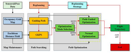
Figure 1.
An overview of the proposed real-time replanning method for fast autonomous flight based on geometric path guiding. The red arrow represents the execution procedures of the method, and the black arrow represents that one part provides information for another part.
The algorithm is mainly divided into three parts: map maintenance, path searching, and path optimization. The main contents of each part are as follows:
- Map maintenance: this algorithm maintains the occupancy grid map and Euclidean distance field map (EDF). The occupancy grid map is updated in real-time using the information obtained by sensors during flight, and the obstacle information is recorded to provide services for the generation of a guiding path. The Euclidean distance field is only maintained by using the information obtained from current sensors to serve path planning and optimization.
- Path searching: At first, we use occupancy grid map and pose data to quickly generate a collision-free and passable geometric guiding path. Then, using the obstacle information maintained by the occupancy grid map, we perceive the surrounding space that the guiding path passes through and judge whether it passes through a narrow space. Next, under the help of the guiding path, the guided kinodynamic path searching (GKPS) method is designed to quickly generate a dynamically feasible, safe, and low-cost initial path.
- Path optimization: We design an adaptive optimization function with two optimization modes, normal optimization (NO) and path-guided optimization (PGO). According to the perception results of the guiding path to the narrow space, the path optimization mode is selected adaptively to optimize the initial path. Finally, a smooth, safe, and feasible path that meets the autonomous and fast flight of UAVs is generated.
2.1. Map Maintenance
The map stores the information of obstacles perceived by sensors, which is the basis of path planning. Due to the rapid flight of the UAV in an unknown environment, a reasonable and efficient map maintenance strategy can not only improve the speed of path replanning, but also ensure the quality of path planning. To improve the efficiency of map maintenance and ensure the quality of the map simultaneously, this paper adopts two kinds of maps—the occupancy grid map and EDF [46], respectively.
The occupancy grid map divides the space into a three-dimensional grid with a fixed resolution and stores the environment information by corresponding the perceived obstacle information to the grid. The occupancy grid map is simple and easy to maintain, so this paper uses an occupancy grid map to store the obstacle information sensed by UAV sensors during flight, which provides a guarantee for planning a stable and safe local geometric path. For efficiency, we only update the grid within the sensor range when maintaining the map.
However, although the occupancy grid map can effectively maintain the information of obstacles, it can only provide help for the generation of the guidance path due to its fineness and can not provide accurate information in path optimization. To solve this problem, we maintain a local EDF for path optimization while maintaining the occupancy grid map. Although EDF also depends on a three-dimensional grid, the accuracy of distance and gradient information can be improved by trilinear interpolation [38]. Besides, due to the high maintenance cost of EDF, we only maintain the area within the sensor range to improve the maintenance efficiency.
2.2. Path Searching
Path searching is the first step of path generation. The quality of the initial path not only determines the pressure of the optimization part but also affects the quality of the final flight path. Although the path optimization part can optimize the path, it is only a trade-off between the smoothness, safety, and dynamic feasibility, the overall running direction and the route of the path do not change much, so a stable, safe, and smooth initial path is very important. This paper proposes an initial path searching method, namely guided kinodynamic path searching (GKPS) which uses a guiding path to lead the KPS. The method can not only obtain a stable, smooth, and safe initial path but also sense whether the path passes through the narrow space in advance to help the path optimization part. We will introduce our method in the following three parts: guiding path generation, scene perception, and guided kinodynamic path searching. The first part is used to introduce the generation method of the guiding path. The second part is to show how to perceive the narrow space by using the guiding path. And the third part is responsible for explaining how to use the guiding path to lead the KPS.
2.2.1. Guiding Path Generation
The purpose of this part is to generate a geometric guiding path with strong safety in the occupancy grid map. According to the different tasks, guiding path generation is divided into two subparts: improved A* and path pruning. The former is designed to generate an initial geometric path; the latter is designed to generate a reasonable guiding path by pruning the initial geometric path.
- A.
- Improved A*
At present, many algorithms can be chosen to generate a geometric path, such as A* [47] and RRT [48]. But compared with RRT, A* is easier to reach the local boundary and control the path not to pass through a particularly narrow space, so we adopt A* here. A* is a classical algorithm in the field of path planning that can search a geometric path stably and quickly. However, the conventional A* is not suitable for us due to the fact that it does not consider the current motion state and generates a geometric path from the start point to the end point instead of a local path. In order to solve these problems and generate a reasonable guiding path, we designed an improved A*, as shown in Algorithm 1.
| Algorithm 1: Improved A* | |
| Input: Current position and velocity , target position Output: A geometric path PA* from the current position to the target position 1 Initialize(); 2 While !P.empty() do 3 nc P.pop(), C.insert(nc); 4 if ReachGoal(nc) || ReachEdge(nc) then 5 return RetrievePath(); 6 expendNodes Expend(nc); 7 for ni in nodes do 8 if !C.contain(ni) ^ CheckFeasible() then 9 gtemp ni.gc + EdgeCost(ni); 10 if !P.contain(ni) then 11 P.add(ni); 12 else if gtemp >= ni.gc then 13 continue; 14 end if 15 ni.parent nc, ni.gc gtemp; 16 ni.fcni.gc + Heuristic(ni); 17 end if 18 end 19 end while | |
The main search process of improved A* is basically consistent with the standard A* algorithm. P and C in line 3 represent the unexpanded Node queue and the expanded Node set, respectively. Before each expansion, we use the function ReachGoal() and ReachEdge() in line 4 to check whether it reaches the target node or the boundary. Then, the function Expand() in line 6 is designed to expand adjacent nodes into the expendNodes set based on the current node, and the function Checkfeasible() in line 8 is used to determine whether the node in expendNodes is safe and reliable in the map environment. If a node meets the conditions, a structure Node is used to record the node index, parent node, gc, and fc cost, where gc is the expansion cost between the node and its parent node, fc is the total cost from the start point to the target point calculated by the sum of gc and the result of the function Heuristic() in line 16. The function Heuristic() represents the cost between the current node to the target node, which is essential for path searching and its quality directly affects the speed and quality of path generation. Next, we add the Node to the queue P, and then choose the Node with the smallest fc to do a new expansion until reaching the target node or boundary.
Different from the conventional A*, in order to avoid the path through a particularly narrow space, we modify the function Expand() in line 6 by a specific expansion strategy, where the node can only be expanded when no obstacle is in the s (we set s = floor()) nodes adjacent to the node. In order to avoid invalid searching in unknown environments, we stop the searching not only when the UAV reaches the target point but also when it reaches the horizontal radar boundary. Besides, the path searched by A* does not consider the current motion state, so in order to ensure the smoothness and safety of the flight trajectory guided by the path, we design a new function Heuristic(), which takes the current motion state and unknown space risk into account:
where is the Euclidean distance between the current node position and the target point, is the angle between the node expansion direction and the velocity direction, N is the node expansion time, and R is the expansion risk coefficient. is used to speed up the path search process, and is adopted to avoid the situation that a large difference between the geometric path direction and the speed direction makes the flight path swerve. In addition, because the radar range in the z-axis direction is often lower than that of the XY axis, it may be necessary to expand the nodes in the unknown exploration area. Therefore, this algorithm adds the node risk coefficient in the heuristic function to make the path within the radar range as far as possible, but it also expands the nodes in the unknown space when necessary.
- B.
- Path Pruning
As shown in Figure 2, the path PA* generated by improved A* (green grid path) sometimes detours, which reduces its guiding performance and affects the smoothness of the initial path. In order to make the path PA* have a stable and efficient guiding ability, a new path Pnew is generated by using Algorithm 2 to prune PA* generated by A* (illustrated in Figure 2). Algorithm 2 is mainly divided into three steps. Firstly, Algorithm 2 iteratively detects each path node in path PA* (Line 2); if a node pA* in path PA* is invisible from the last node of path Pnew (Line 3, 4), then it obtains the first occlusion node pb which affects the intervisibility of the two nodes by the function BlockVoxel() (Line 5). Secondly, a relay node pn is found by pushing away from obstacles in the direction orthogonal to lA* and coplanar to the ESDF gradient at pb (Line 6), after which appending pn to path Pnew. Finally, the algorithm iterates the process until all PA* nodes are detected and generates a more concise and oriented path Pnew.
| Algorithm 2: Pruning PA* to Pnew | |
| Input: the path PA* generated by Algorithm 1 Output: a shortcut path Pnew for PA* 1 Pnew PA*.front() 2 foreach pA* PA* do 3 lA* Line(Pnew.back(), pA*) 4 if !LineVisible(lA*) then 5 pb BlockVoxel(pA*) 6 pn PushAwayObs(pb, lA*) 7 Pnew.push_back(pn) 8 end if 9 end 10 Pnew.push_back(pA*.back()) 11 return Pnew | |
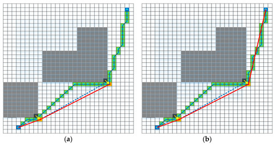
Figure 2.
A detoured and long improved A* path (green path) is pruned. For each node of the path, its visibility to the last waypoint of the pruned path (red path) is checked. The blocking voxels (black voxel) are pushed and appended as new waypoints (orange voxel). Sub-figure (a) shows the way to prune when it is not visible, and sub-figure (b) shows the way to prune when it is visible.
2.2.2. Scene Perception
The guiding path generated above is not only adopted to guide KPS to generate the initial path but is also used to guide the selection of the optimization mode according to the environmental information around the path. Therefore, after obtaining the path, as shown in Figure 3, we use it to find the narrow space by sensing the surrounding environment that the path passes through according to the maintained occupancy grid map. At first, the algorithm discretizes the path Pnew to Pd according to the resolution. Then, it judges whether a point pi in Pd is in the narrow space by calculating whether there are obstacles simultaneously in the distance r between the two ends of the direction orthogonal to the forward direction of Pd. To simplify the decision process, we only judge the orthogonal vectors in 0°, 45°, 90°, and 135°. Finally, if there is a point pi in the narrow space (as shown in point p3), and the distance d from the starting point of the guide path p0 to the point pi is less than dthr, we set Rp = true and trigger the narrow space searching and optimization mode.
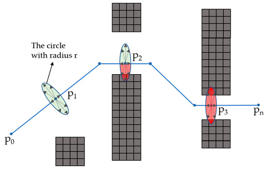
Figure 3.
Using the guiding path (blue path) to perceive the narrow space. The green circle represents the point in spacious space, and the red circle represents the point in narrow space.
2.2.3. Guided Kinodynamic Path Searching
Although the guiding path generated above is safe, it is not suitable as the initial path because it is a geometric path without considering the dynamic feasibility. Therefore, in order to find a high-quality initial path, the kinodynamic path searching (KPS) method [39] is adopted. KPS is a method originated from the hybrid-state A* search [49] first proposed for the autonomous vehicle, which can find a safe and kinodynamically feasible trajectory that is minimal with respect to time duration and control cost in a voxel grid map. The searching loop of this method is similar to Algorithm 1; the differences are as follows: (1) the path generated by this method is not a simple geometric route, but a trajectory conforming to the dynamic feasibility of the UAV; (2) this method does not expand by directly searching adjacent nodes like A*, but through motion primitives generated by control space sampling; (3) it is different between Algorithm 1 and this method to determine whether a node can be expanded. This method not only needs to judge whether the sampling route is safe but also needs to determine whether the quadrotor dynamics are feasible; (4) this method uses the input of acceleration and time to calculate the extended energy consumption.
However, as the KPS depends on the discrete control space, this method loses some spatial information. In order to solve the problem, as shown in Figure 4, we propose a guided kinodynamic path searching method (GKPS) according to the guiding path, which can generate a safe, dynamically feasible and purposeful path that is minimal with respect to time duration and control cost in a voxel grid map. We will introduce GKPS through the following four parts: primitives generation, the actual cost, adaptive heuristic function, and direct expansion strategy. Primitives generation is used to show how to extend the node. The actual cost is used to introduce the calculated method of the trajectory cost. The adaptive heuristic function is designed to follow the guiding path and speed up the searching process, and the part of the direct expansion strategy is designed to reduce the useless expansion and accurately reach the end position.
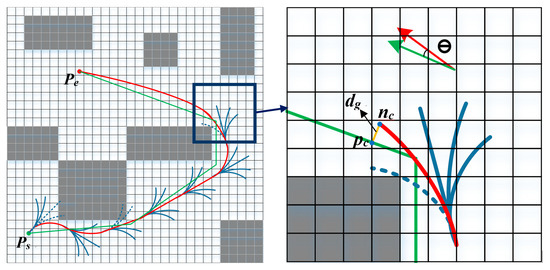
Figure 4.
An illustration of the mechanism of the guided kinodynamic path searching (GKPS) method. Blue curves indicate the motion primitives generated by Equation (3). The green path is the guide path generated by pruning A*. The red curve is the result of the search.
- A.
- Primitives Generation
The differential flatness of the quadrotor UAV system enables us to represent the flight path by three independent 1-D time-parameterized polynomial functions, as shown in Equation (2):
where . From the view of quadrotor systems, it corresponds to a linear time-invariant (LTI) system. Let be the state vector. Let be the control input. The state-space model can be defined as:
The complete solution for the state equation is expressed as:
which gives the trajectory of the quadrotor system whose initial state is and control input is . We selected n = 2 in practice.
In node expansion, we uniformly discretize the control space of each axis as ( is a nonzero positive integer, we select = 2). According to the current quadrotor state (including position and speed), the end state of flight in duration can be calculated and regarded as an extended candidate node.
However, not all generated nodes can be extended. We need to check the candidate node in the following aspects: (1) check whether the node is in the maintained local map; (2) check whether the state speed of the node exceeds the limit; (3) check whether the node moves far enough from the parent node; (4) discretely sample the extended path of the node, and judge whether the distance between the sampling point and the obstacle is greater than the specified threshold one by one. If the candidate node meets all the above conditions at the same time, it will be included in the extended node; otherwise, it will be abandoned.
- B.
- Actual Cost
The purpose of GKPS is to generate a safe, dynamically feasible, and low-energy initial path. The safety and dynamic feasibility have been guaranteed through Part A. To ensure the trajectory is optimal in time and control cost, this part designs the cost of a trajectory as:
Under this definition, we can calculate the expansion consumption from the parent node to the current node. Assuming the current node is , the control input of the expansion is , and the consumption time is , we can calculate the current expansion consumption by . At the same time, the cumulative consumption from the start point to the current point can be calculated by:
- C.
- Adaptive Heuristic Function
Normally, the heuristic function is used to speed up the searching process. However, in order to reduce the impact of spatial information loss on the path quality, we limit the searching range of the KPS in the vicinity of the guiding path by designing a new heuristic function that can generate a safe and smooth path under the guidance of the guiding path.
Instead of regarding the minimum energy cost between the current point and the target point as the main part of the heuristic function in [39] where can be calculated by applying the Pontryagins minimum principle [50], we incorporate the spatial relationship between the current point and the guiding path into the heuristic function. As shown in Figure 4, and are the current point and endpoint of the guiding path. is the shortest distance between the node and the point of the guiding path. is the angle difference between the current velocity direction and the guiding direction. In order to make the path searching not only efficient but also generate a smooth trajectory in the vicinity of the guiding path, we designed the heuristic function as:
where is the distance between and in the guiding path, which is used to improve the efficiency of the search process. is responsible for constraining the path searching to search according to the direction of the guiding path. is used to help the method to find a smoother path.
However, due to the non-uniformity of the obstacles in the environment (there are spacious areas and narrow areas), it is difficult for a single fixed heuristic function to be efficient in a cluttered environment. In order to improve the quality of the initial path in the narrow areas, we adopt adaptive values for and according to the perception result Rp of the guiding path. When the guiding path perceives that it needs to pass through the narrow space, it will send out the signal that the path is not safe, and then enhance the guiding constraint when searching the path in this area by improving the and , which makes the search path easier to pass through the narrow space. This design makes the path search results smooth in the spacious space and improves the quality of the path in the narrow space.
- D.
- Direct Expansion Strategy
GKPS is a method based on discretized control space. Although we add a guiding path to guide, it is still impossible to accurately reach the end position. In addition, when the target point appears in the radar range, if the current node is very close to the target point or the surrounding environment is relatively empty, according to the conventional searching method, it will waste a lot of time for useless expansion and unnecessary replanning. To solve the problem, [39] induced an analytic expansion scheme and triggered the expansion when the current position and the target position are less than the threshold. However, the effectiveness of the method depends on the selection of threshold, which is not stable. For this, we designed the direct expansion strategy based on the guiding path to improve the efficiency of GKPS, which can make the route reach the destination quickly and accurately.
As shown in Figure 5, GKPS selects different execution processes according to the guiding path. When the guiding path reaches the local boundary, GKPS executes the normal process introduced above (black line). However, when the guiding path reaches the goal, the direct expansion strategy (red line) is triggered, which mainly includes the following steps:

Figure 5.
The detailed process of GKPS, when the guiding path reaches the goal, the direct expansion strategy (red arrow) is executed. Otherwise, GKPS executes the normal process (black arrow).
- Judge whether the guiding path reaches the endpoint. If it reaches the endpoint, start the expansion strategy and carry out the next step (red line). Otherwise, carry out the normal GKPS process (black line);
- Analyze the guiding path. If the number of remaining nodes N of the guiding path is not more than three, then it is considered that the road environment is relatively spacious, and directly carries out step 4. Otherwise, carry out the next step;
- Carry out the normal GKPS, but after each node expansion, execute step 2;
- Direct expansion process, which generates an accurate path from the current node to target point by using the same approach in [39]. If the route is safe and reliable, stop the path searching and enter the path optimization part, otherwise continue to step 3.
2.3. Adaptive Trajectory Optimization
Although Section 2.2 generates a trajectory that is safe and dynamically feasible, it is not optimal in theory as it depends on the discretized control inputs, causing the loss of spatial information and rough path. In addition, the path is very close to the obstacle as it does not consider the distance information in the free space. Therefore, we need to optimize the trajectory generated by GKPS in the aspects of smoothness and safety. In this part, we use B-spline to optimize the trajectory in terms of smoothness, safety, and dynamic feasibility. Besides, according to the perception of the guiding path to the narrow space, an adaptive optimization method for complex environments is proposed. We design two different cost functions in the method for spacious and narrow areas, respectively. According to the perception results of the guiding path, the method chooses a better optimization mode and produces a smooth, safe, and dynamically feasible path in a short time. We will introduce our adaptive trajectory optimization method by the following two parts: uniform B-splines and adaptive cost function. The former is to introduce the model and characteristics of uniform B-splines, and the latter is used to introduce our adaptive optimization function.
2.3.1. Uniform B-Splines
The value of a B-spline of degree can be evaluated using the following equation:
where are control points at times and is the basic function that can be calculated by the De Boor-Cox recursive formula. For a uniform B-spline, there is a fixed time interval between their control points, which simplifies the computation of the basis functions. In the case of uniform B-splines of degree , at time , the position depends only on k consecutive control points, namely . We transform time to uniform representations . Following the matrix representation of the De Boor-Cox equation, the value of the function can be evaluated as follows:
where is a constant matrix determined by . In our implementation, k is set as 4. The evaluation of the derivatives is the same since the derivative of a B-spline is also a B-spline. As shown in Figure 6, with the help of the convex hull characteristics of the B-spline, we can optimize the trajectory to meet the requirements of safety and dynamic feasibility. The dynamic feasibility can be ensured by constraining all the velocity and acceleration control points to satisfy and , in which and . The safety can be satisfied by ensuring , is the distance between the obstacles and any point Q in the convex hull. Through the derivation of the geometric relationship, we can ensure the safety of the trajectory by simply satisfying .
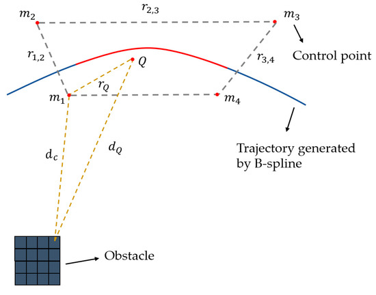
Figure 6.
A trajectory (blue line) is represented by a B-spline (k = 4), bounded by the corresponding convex hull of the control points (example convex hulls and segments are shown in gray and red). An illustration of ensuring a convex hull of the B-spline is collision-free.
2.3.2. Adaptive Cost Function
The purpose of the optimization part is to improve the smoothness and clearance of the path by using a cost function to make a trade-off between safety, smoothness, and dynamic feasibility. However, there are both spacious and narrow spaces in the actual flight environment, so it is difficult for a fixed cost function to maintain an efficient optimization performance throughout the whole flight. To solve this problem and improve the stability of the optimization module, we propose an adaptive optimization function according to the perception results of the guiding path. We define the overall function as:
where is the smoothness cost, is the collision cost, and they are defined as [39]:
where is defined by using a jerk-penalized elastic band cost function, is the distance between and the closest obstacle, is the expected path clearance. and are the dynamic feasibility cost, and its formulations are similar to Equation (13). is the distance cost between B-spline optimization path and guiding path, which is defined as:
where Rp is the perception result of the guiding path, is the control point of B-spline, is the associated point with on the guiding path, which is uniformly sampled along the guiding path. Because the B-spline curve is covered by the convex hull of control points, we simply define by the Euclidean distance between and .
As shown in Figure 7, in order to improve the stability of optimization function, especially the optimization quality in narrow space, we design two optimization modes according to the perception results of the guiding path to the surrounding environment, which are the normal optimization mode (NO) and path-guided optimization mode (PGO). NO is used for path optimization in spacious space (), which optimizes the trajectory by trading off the smoothness, dynamic feasibility, and safety of the path. In this optimization mode, it can be seen from Equation (14) that = 0, so the overall function is changed as follows:
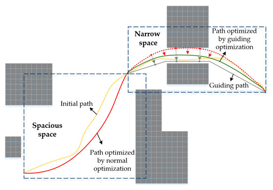
Figure 7.
Trajectories are optimized by different optimization modes according to the different environments. The guiding path is the path generated in Section 2.2.1 and the initial path is generated by GKPS in Section 2.2.3.
When we find a narrow space and the position of the narrow space is very close to the current position (), we trigger the PGO, which uses Equation (11) as the overall function that regards the sum of the squared Euclidean distance between and as part of the cost function to attract the optimized route to the guiding path for path safety.
In addition, it should be noted that in order to make the generated flight trajectory safer, we take the distance between the trajectory and the obstacles into account in Equation (11). Although this can make the overall trajectory away from the obstacles, it also lengthens the trajectory. Therefore, the quadrotor has to fly a longer distance within the same time, which unavoidably causes over aggressive motion if the original motion is already near to the physical limits. For this, we use the time adjustment method [39] to optimize the time allocation, which makes the trajectory feasible by detecting and appropriately extending the flight time of the path overstepping the physical limits.
3. Experimental Results
3.1. Experimental Details
To validate the effectiveness of the proposed real-time path planning method, as shown in Figure 8, the comparisons were done on a map randomly deployed with five different obstacle densities and the maximum velocity and acceleration limits were set as 3 m/s and 2 m/s2, respectively, where we tested our method with several state-of-the-art methods—FASTER [27], RET [39], and PGO [40]. FASTER is one of the hard-constrained methods, which obtains high-speed trajectories by optimizing the trajectory in both free-known space and unknown spaces, and the safety is guaranteed by having a feasible, safe back-up trajectory in the free-known space. RET introduced a path searching method based on constraints of dynamic feasibility, which can provide a more reasonable initial path. In addition, it deeply explores the convex hull characteristics of the B-spline and applies them to path optimization and time allocation. PGO uses a topological path searching algorithm to obtain a set of typical paths in the environment. The path in the set is used to guide the path for preliminary optimization, and then re-optimizes through the optimization method of RET to obtain the final flight path. To a certain extent, this method solves the problem of local optimization failure and improves the success rate of planning. In addition, both our method and RET adopt the grid map in path searching, so we also compare the effectiveness of the two methods in four different grid resolutions. For a fair comparison, we use the open-source implementation of FASTER, RET, and PGO; their default parameter settings are adopted in this paper.
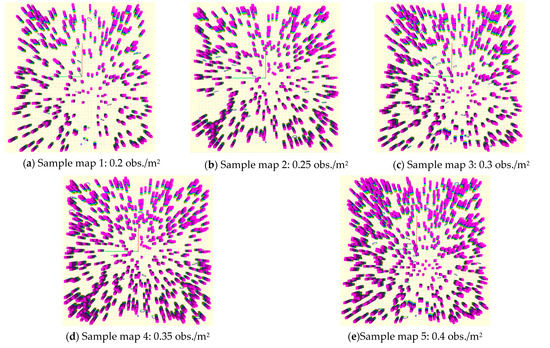
Figure 8.
Samples of the maps generated by different obstacle densities.
Our method is mainly for the unknown environment, so we need to constantly do replanning within the limited sensing according to certain rules to adapt to changes in the environment. In this paper, the replanning rules are designed as follows: (1) the distance between trajectory and obstacle is less than 0.1 m; (2) the flight distance of the UAV is more than 2 m. When either of the above two conditions are met, a replanning is carried out according to the latest environmental information.
We present tests in simulation and use a simulating tool containing the quadrotor dynamics model, random map generator, and local sensing filter. All simulations run on an Intel Core i9-8950HK CPU and GeForce P2000 GPU. The trajectory optimization is solved by a general non-linear optimization solver Nlopt.
3.2. Benchmark Comparisons
3.2.1. Efficiency Analysis under Different Obstacle Densities
Obstacle density is a key parameter to simulate the complexity of the real scene. The larger the obstacle density, the more complex the environment, and the higher the requirements for the performance of the planning algorithms. Under different obstacle densities, we compared our method with FASTER, RET, and PGO. As shown in Figure 8, under the same experimental conditions and environment, we tested the three methods under five obstacle densities. Ten maps were randomly generated for each obstacle density, and five experiments were carried out for each map. The experiment results such as average flight distance, flight time, energy consumption, success rate, computation time of each replanning, and total replan time and number in each flight were recorded.
As is shown in Figure 9 and Table 1, it can be seen that our method outperforms others in the aspects of energy consumption and success rate. In flight time and flight distance, we are second only to FASTER. In the computation of each replanning, we are second only to RET. Although FASTER is better than our method in flight time and flight distance, the efficiency of FASTER is much lower than our method in the aspects of energy consumption, total replan number, total replan time, and the computation time of each replanning. Furthermore, although RET takes the least time for each replanning, it does not perform well in other aspects, especially with the increase of obstacle density, which decreases its success rate rapidly. Besides, PGO solves the local minima issue by using the guiding path, which improves the replanning success rate, but it costs more time to do a replanning, and its flight distance is much higher than other methods. Compared to them, the proposed method can steadily and rapidly generate a high-quality trajectory in different obstacle densities with the help of the guiding path.
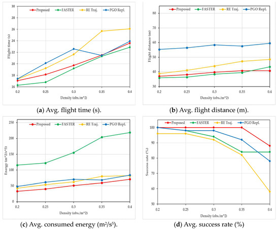
Figure 9.
Results of the comparisons between the proposed method and FASTER, RET, PGO in different obstacle densities.

Table 1.
The comparisons of three planning methods in Replan.
As shown in Figure 10, we also compared and analyzed the distribution of the experimental results of flight time, flight distance, and energy consumption. Special attention should be paid to that due to the situation of flight failure, so in order to show the results, when a method fails under a certain obstacle density, we regard the average of the experimental results of the method in the density as the experimental results. It can be seen from the experimental distribution results that compared with the other three methods, the experimental results of our method in each aspect under different obstacle densities are more concentrated, and the results do not fluctuate greatly due to the change of environment, so the stability of this method is higher. In addition, although the average values of the experimental results of RET in each aspect are higher than our method and FASTER, it can be seen that the lower limit distribution of the experimental results of RET is lower than other methods when the obstacle density is low. This phenomenon shows that the efficiency of RET is better than our method in some experimental environments, and it can achieve a shorter flight time.
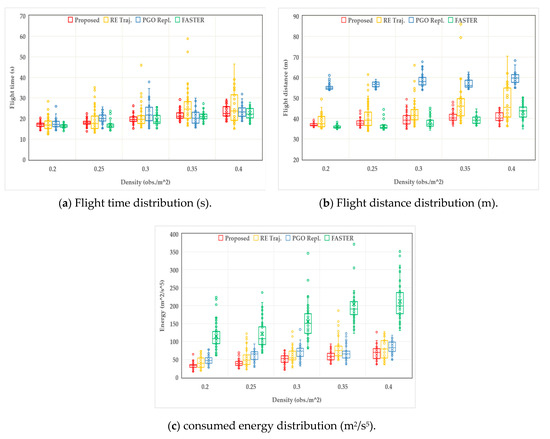
Figure 10.
The distribution comparisons of the experimental results between the proposed method, FASTER, RET, and PGO in different obstacle densities.
3.2.2. Efficiency Analysis under Different Resolution
The resolution of voxel grids is a critical factor for the performance of the proposed method and RET due to the two methods both adopting the occupancy grid map in path searching. Therefore, we tested the effectiveness of the two methods in different grid resolutions. As shown in Figure 11, under the premise of obstacle density of 0.2 obs./m2, we compared the above two methods in flight time, flight distance, flight cost, replanning time, flight success rate, and other parameters in four different resolutions. Ten maps were randomly generated under each resolution; five experiments were carried out for each map.
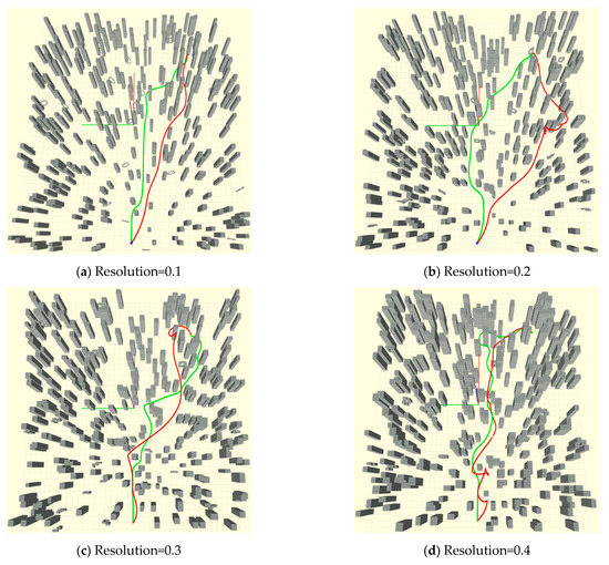
Figure 11.
Samples of the maps and trajectories generated by the proposed method (green) and RET (red) in different resolutions.
As shown in Table 2, the efficiency of the proposed method and RET are both affected by a decrease in grid resolution. The indexes including average flight time, average flight distance, average flight energy cost, and average planning cost all increase significantly, and the flight success rate decreases sharply. Besides, it can be seen from the result that although the efficiency of the proposed method also gradually decreases, its performance is better than RET except for the single replanning time. Moreover, as shown in Figure 12, we also compared the experimental result distribution of two methods, and the results are similar to those under different obstacle densities. The experimental results of the proposed method are more aggregated in flight time, flight distance, and flight energy cost, indicating that the planning efficiency of this method is also efficient and more stable than RET in different resolutions.

Table 2.
The comparisons of two planning method.
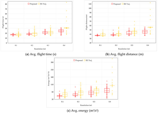
Figure 12.
Results distribution of the comparisons between the proposed method and RET in different resolutions.
3.2.3. Comparison of Performance before and after Optimization
The proposed method is mainly divided into two parts: path searching and path optimization. The purpose of the path searching is to generate a high-quality initial path that meets the dynamic constraints, and path optimization is used to improve the safety and smoothness of the initial path. In order to verify the necessity of the optimization part and its impact on the quality of path generation, we compared and analyzed the path generation results of the proposed method and the method that only uses the path searching part (no-opt). The experimental results are shown in Table 3 and Figure 13.

Table 3.
The comparisons of the proposed method and no-opt.
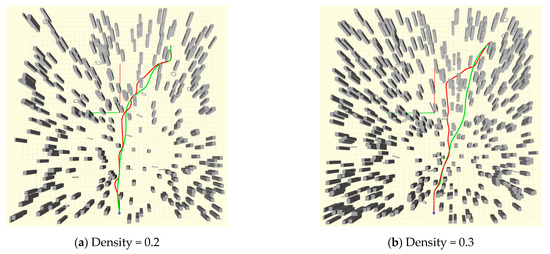
Figure 13.
Samples of the trajectories generated by the proposed method (green) and no-opt (red) in different densities.
As shown in Table 3, we compared the proposed method and the no-opt method in two different obstacle densities. The experimental results show that the two methods have little difference in average flight time and average flight distance, but there are obvious differences in the average flight energy cost and replanning time. No-opt takes less time than the proposed method to do a replanning. However, although the replanning time of the proposed method is slightly higher, it can still meet the real-time requirements. Besides, due to the optimization part, the energy cost of the proposed method is greatly reduced. As shown in Figure 13, the path generated by no-opt is close to the obstacles and not smooth, but due to the refining of the optimization part in the proposed method, the smoothness and safety of the flight path generated by the proposed method is greatly improved, which improves the flight stability and reduces the pressure of the flight control.
4. Discussion
In this paper, a real-time path planning method based on geometric path guiding (RETRBG) is proposed, which can provide a stable and efficient planning service for UAV autonomous fast flight in an unknown environment. Based on the work published by [39], this paper improves the quality of the flight trajectory by modifying path searching and path optimization. In path searching, firstly, this paper adopts the occupancy grid map to maintain the scene information obtained by sensors during the flight of UAV. Based on the occupancy grid map, a collision-free geometric path in the local range is generated according to an improved A* and path pruning method. Secondly, we use the guiding path to perceive the surrounding environment to obtain information on a narrow space; thirdly, an initial path is generated by guided kinodynamic path searching (GKPS). Our method in path searching can not only retain the advantages of kinodynamic path searching (KPS) but also improves the safety of the initial path and offsets the space information loss caused by sampling control space due to the help of the occupancy grid map and the guiding path. In path optimization, this paper proposes an adaptive optimization function with two optimization modes. According to the perception result of the guiding path towards the narrow space, the optimization function is automatically selected. If it does not pass through a narrow space, we optimize the path by using the NO optimization, which trades between safety, smoothness, and dynamic feasibility. If the guiding path shows that the UAV will pass through a narrow space, the PGO mode will be selected, where the distance between the trajectory and the guide path is added as a parameter to the cost function, which improves the safety of the trajectory by guiding the optimization direction to generate a smooth trajectory in the vicinity of the guiding path. Therefore, our method can not only avoid the local minimum problem that the optimization function may suffer but also improves the optimization quality and success rate in the narrow space by using the adaptive cost function guided by the geometric guiding path.
In order to verify the effectiveness of the proposed method, we made a series of comparative experiments. At first, we compared the proposed method with several state-of-the-art methods, namely FASTER, RET, and PGO under five different obstacle densities. The experimental results show that: (1) RET takes the shortest time to do a replanning, and its performance is better when the obstacle density is low. However, due to the fixed optimization function and the trade-off between smoothness, safety, and dynamic feasibility in it, when the path is generated in a narrow space, the safety of the trajectory is easily weakened, which may cause the optimized path to be close to the obstacle or even pass through the obstacle; the method regards the area not perceived as a collision-free area, and it only maintains the local map perceived by the field of view, so it is easy to fall into a dead end. The above two reasons are easy to make the planning efficiency and success rate decrease, and the number of replannings gradually increase. The distribution of the experimental results proves the analysis; with the increase of the obstacle density, it can be seen that its performance is unstable, and the quality of the flight trajectory and the success rate gradually decrease. (2) Due to the use of the guiding path, PGO avoids the local minimum problem that other gradient-based methods may suffer, which improves the success rate and the quality of the flight trajectory. However, it still suffers the problem of poor planning quality in narrow areas, and it takes the most time among the three methods to execute a replanning due to the process of the generation and selection of multiple paths. The experimental results also prove this, compared with RET, PGO obtains a high quality and success rate. (3) FASTER obtains high-speed trajectory by optimizing the trajectory in both the free-known and unknown spaces. It also adopts a mixed integer quadratic program (MIQP) formulation to obtain a more reasonable time allocation of the trajectories. However, it costs much more time than other methods due to the MIQP formulation, and the path generated by this method may be very close to the obstacle due to the hard-constrained optimization. (4) Compared to them, the proposed method performs well in all aspects including average flight time, flight distance, energy cost, and planning success rate under different obstacle densities and grid resolutions. In the energy consumption and success rate, the proposed method outperforms others. In the flight time and distance, the proposed method is second only to FASTER. Meanwhile, according to the distribution of experimental results in different random maps under the same obstacle density, it can be seen that compared with the other methods, the experimental results of our method in different maps are more concentrated, which shows that the performance of the proposed method is more stable in different environments. The results can be explained by the following: At first, the proposed method uses the occupancy grid map to maintain the obstacle information perceived by the sensors in the flight process and to generate the geometric guiding path, which can effectively avoid the planning failure caused by the dead-end of the flight. During the generation of the guiding path, we take the motion state into account, which avoids the sharp turn phenomenon caused by the deviation between the guiding direction and the moving direction. Then, aiming to improve the safety and reduce the influence of control state sampling in the KPS, we use the guiding path to guide the searching process. Finally, the proposed method uses the guiding path to perceive the surrounding environment and selects the suitable optimization mode according to the perception results, which significantly improve the quality of the trajectory and the ability to pass through the narrow space.
As shown in Figure 14, the flight trajectories generated by the four methods in different obstacle densities also support the above analysis. It can be seen that compared with RET and PGO, the actual flight trajectories of our method are more reasonable. FASTER obtains a high-speed trajectory due to the optimization in both the free-known and unknown spaces, but the path is very close to the obstacle in some places. RET produces a high-quality path in most areas, but it is easily affected by some local environments due to the reason stated above, which leads to the quality degradation of the overall flight trajectory. Additionally, due to the pursuit of smoothness, the flight distance of PGO is significantly larger than the other methods. In addition, due to both the proposed method and the RET depending on the grid map, we also compared the performance of the two methods under four different grid resolutions. The experimental results are similar to the results of different obstacle densities, which shows that our method performs well not only in different obstacle densities but in different grid resolutions.
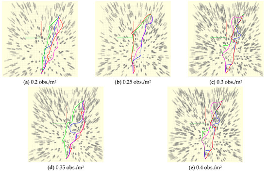
Figure 14.
Trajectories generated by the proposed method (green), FASTER (pink), RET (red), and PGO (blue) in different obstacle densities.
However, although the proposed method has made some improvements in path searching and path optimization, there are still many problems that need to be improved. First of all, although the proposed method improves the quality of the initial path by GKPS that uses the KPS to generate the initial path under the guidance of the guiding path, the path search process will cost more time and the existence of guidance may lead to a relatively slow flight speed. Secondly, the proposed method adopts the time adjustment method proposed by RET. Although the time adjustment method can optimize the part that does not meet the dynamic feasibility, it does not speed up the part with a smaller speed. Moreover, the proposed method depends on the quality of the guide path, but the guide path does not take the factors of dynamic feasibility into account, so if there is an unreasonable guiding path, the quality of the flight trajectory will be poor.
5. Conclusions
In this paper, a robust and efficient trajectory replanning method based on the guiding path (RETRBG) for unknown environments is proposed. The method is mainly improved in two modules: path searching and path optimization. In the path searching module, a safe geometric guiding path is generated firstly in the occupancy grid map by using the improved A* and path pruning method to perceive the surrounding environment. Furthermore, a guided kinodynamic path searching (GKPS) is proposed that can generate an initial path that meets the safety and dynamic feasibility under the help of the guiding path. In the part of path optimization, an adaptive optimization function with two modes is devised. According to the perception result of the guiding path towards the narrow space, the function adaptively selects the optimization mode to optimize the trajectory. We compared the effectiveness of our method with FASTER, RET, and PGO under different obstacle densities, and compared the effectiveness of our method with RET under different grid resolutions. The experimental results show that the proposed method performs well both in the experiments of different obstacle densities and different grid resolutions. Although the replanning time is slightly higher, the performance of our method is more efficient and more stable in different cluttered environments. We compared and analyzed the path generated by the proposed method and no-opt in different environments; the results verify the necessity of optimization and its impact on the quality of path generation.
We also look forward to the next work. First of all, the proposed method depends on the quality of the guiding path, so we will try to figure out how to design a better heuristic function that takes more dynamic feasibility into account to improve the quality of the guiding path in the future. Secondly, although we carried out an extensive effectiveness evaluation of our proposed method, the experiments were only carried out in simulation, so we will make a series of real-world experiments in the next work. Moreover, we will extend our method to adapt to the dynamic environment in the future.
Author Contributions
Y.Z. contributed to the conceptualization of the work; Y.Z. proposed the methodology and designed the experiments; Y.Z. and J.D. performed the experiments and analyzed the data; Y.Z. prepared the original draft and all authors contributed to reviewing and editing the manuscript. This project is under the supervision of L.Y., Y.C., and Y.L. All authors have read and agreed to the published version of the manuscript.
Funding
This research was funded by National Key Research and Development Project of China (Grant No. 2020YFD1100200).
Conflicts of Interest
The authors declare no conflict of interest.
References
- Mohd Noor, N.; Abdullah, A.; Hashim, M. Remote sensing UAV/drones and its applications for urban areas: A review. IOP Conf. Ser. Earth Environ. Sci. 2018, 169, 12003. [Google Scholar] [CrossRef]
- Koch, T.; Körner, M.; Fraundorfer, F. Automatic and Semantically-Aware 3D UAV Flight Planning for Image-Based 3D Reconstruction. Remote Sens. 2019, 11, 1550. [Google Scholar] [CrossRef]
- Dai, J.; Yan, L.; Liu, H.; Chen, C.; Huo, L. An Offline Coarse-To-Fine Precision Optimization Algorithm for 3D Laser SLAM Point Cloud. Remote Sens. 2019, 11, 2352. [Google Scholar] [CrossRef]
- Chen, S.W.; Nardari, G.V.; Lee, E.S.; Qu, C.; Liu, X.; Romero, R.A.F.; Kumar, V. SLOAM: Semantic Lidar Odometry and Mapping for Forest Inventory. IEEE Robot. Autom. Lett. 2020, 5, 612–619. [Google Scholar] [CrossRef]
- Ouyang, J.; Simonson, S.L.; Zhang, Y.; Zhuang, C.; Wang, J.; Chen, Z.; Qiao, Y.; Duan, Y.; Zheng, S. Using UAV technology for basic data collection of Firmiana danxiaensis HH Hsue & HS Kiu, JS (Malvaceae), an important, nationally protected wild plant in Zhanglao Peak, Danxiashan Mountain, South China. IOP Conf. Ser. Earth Environ. Sci. 2020, 467, 12130. [Google Scholar]
- Battulwar, R.; Winkelmaier, G.; Valencia, J.; Naghadehi, M.Z.; Peik, B.; Abbasi, B.; Parvin, B.; Sattarvand, J. A Practical Methodology for Generating High-Resolution 3D Models of Open-Pit Slopes Using UAVs: Flight Path Planning and Optimization. Remote Sens. 2020, 12, 2283. [Google Scholar] [CrossRef]
- Erdelj, M.; Natalizio, E.; Chowdhury, K.R.; Akyildiz, I.F. Help from the sky: Leveraging UAVs for disaster management. IEEE Pervas. Comput. 2017, 16, 24–32. [Google Scholar] [CrossRef]
- Sandino, J.; Vanegas, F.; Maire, F.; Caccetta, P.; Sanderson, C.; Gonzalez, F. UAV Framework for Autonomous Onboard Navigation and People/Object Detection in Cluttered Indoor Environments. Remote Sens. 2020, 12, 3386. [Google Scholar] [CrossRef]
- Pajares, G. Overview and current status of remote sensing applications based on unmanned aerial vehicles (UAVs). Photogramm. Eng. Remote Sens. 2015, 81, 281–330. [Google Scholar] [CrossRef]
- Ramesh, P.S.; Jeyan, J.M.L. Comparative analysis of the impact of operating parameters on military and civil applications of mini unmanned aerial vehicle (UAV). In AIP Conference Proceedings; AIP Publishing LLC: Chennai, India, 2020; Volume 2311, p. 0034. [Google Scholar]
- Xu, B.; Chen, Y.; Zhang, S.; Wang, J. Improved Point–Line Visual–Inertial Odometry System Using Helmert Variance Component Estimation. Remote Sens. 2020, 12, 2901. [Google Scholar] [CrossRef]
- Chen, Y.; Yan, L.; Xu, B.; Liu, Y. Multi-Stage Matching Approach for Mobile Platform Visual Imagery. IEEE Access 2019, 7, 160523–160535. [Google Scholar] [CrossRef]
- Ayhan, B.; Kwan, C. Time-Constrained Extremal Trajectory Design for Fixed-Wing Unmanned Aerial Vehicles in Steady Wind. J. Guid. Control Dyn. 2018, 41, 1569–1576. [Google Scholar] [CrossRef]
- Ayhan, B.; Kwan, C.; Budavari, B.; Larkin, J.; Gribben, D. Preflight Contingency Planning Approach for Fixed Wing UAVs with Engine Failure in the Presence of Winds. Sensors 2019, 19, 227. [Google Scholar] [CrossRef]
- Eng, P.; Mejias, L.; Liu, X.; Walker, R. Automating human thought processes for a UAV forced landing. J. Intell. Robot. Syst. 2010, 57, 329–349. [Google Scholar] [CrossRef]
- Mejias, L.; Eng, P. Controlled emergency landing of an unpowered unmanned aerial system. J. Intell. Robot. Syst. 2013, 70, 421–435. [Google Scholar] [CrossRef][Green Version]
- Mellinger, D.; Kumar, V. Minimum snap trajectory generation and control for quadrotors. In Proceedings of the 2011 IEEE International Conference on Robotics and Automation, Shanghai, China, 9–13 May 2011; pp. 2520–2525. [Google Scholar]
- Richter, C.; Bry, A.; Roy, N. Polynomial trajectory planning for aggressive quadrotor flight in dense indoor environments. In Robotics Research; Springer: Singapore, 2013; pp. 649–666. [Google Scholar]
- Ding, W.; Gao, W.; Wang, K.; Shen, S. An efficient b-spline-based kinodynamic replanning framework for quadrotors. IEEE Trans. Robot. 2019, 35, 1287–1306. [Google Scholar] [CrossRef]
- Gao, F.; Shen, S. Online quadrotor trajectory generation and autonomous navigation on point clouds. In Proceedings of the 2016 IEEE International Symposium on Safety, Security, and Rescue Robotics (SSRR), Lausanne, Switzerland, 23–27 October 2016; pp. 139–146. [Google Scholar]
- Liu, S.; Watterson, M.; Mohta, K.; Sun, K.; Bhattacharya, S.; Taylor, C.J.; Kumar, V. Planning Dynamically Feasible Trajectories for Quadrotors Using Safe Flight Corridors in 3-D Complex Environments. IEEE Robot. Autom. Lett. 2017, 2, 1688–1695. [Google Scholar] [CrossRef]
- Chen, J.; Su, K.; Shen, S. Real-time safe trajectory generation for quadrotor flight in cluttered environments. In Proceedings of the 2015 IEEE International Conference on Robotics and Biomimetics (ROBIO), Zhuhai, China, 6–9 December 2015; pp. 1678–1685. [Google Scholar]
- Ding, W.; Gao, W.; Wang, K.; Shen, S. Trajectory Replanning for Quadrotors Using Kinodynamic Search and Elastic Optimization. In Proceedings of the 2018 IEEE International Conference on Robotics and Automation (ICRA), Brisbane, Australia, 21–25 May 2019. [Google Scholar]
- Gao, F.; Wang, L.; Zhou, B.; Zhou, X.; Pan, J.; Shen, S. Teach-repeat-replan: A complete and robust system for aggressive flight in complex environments. IEEE Trans Robot. 2020. [Google Scholar] [CrossRef]
- Ye, H.; Zhou, X.; Wang, Z.; Xu, C.; Chu, J.; Gao, F. TGK-Planner: An Efficient Topology Guided Kinodynamic Planner for Autonomous Quadrotors. IEEE Robot. Autom. Lett. 2020. [Google Scholar] [CrossRef]
- Gao, F.; Wu, W.; Gao, W.; Shen, S. Flying on point clouds: Online trajectory generation and autonomous navigation for quadrotors in cluttered environments. J. Field Robot. 2019, 36, 710–733. [Google Scholar] [CrossRef]
- Tordesillas, J.; Lopez, B.T.; Everett, M.; How, J.P. Faster: Fast and safe trajectory planner for flights in unknown environments. arXiv 2020, arXiv:2001.04420. [Google Scholar]
- Liu, S.; Watterson, M.; Tang, S.; Kumar, V. High speed navigation for quadrotors with limited onboard sensing. In Proceedings of the 2016 IEEE International Conference on Robotics And Automation (ICRA), Stockholm, Sweden, 16–21 May 2016; pp. 1484–1491. [Google Scholar]
- Tordesillas, J.; Lopez, B.T.; Carter, J.; Ware, J.; How, J.P. Real-Time Planning with Multi-Fidelity Models for Agile Flights in Unknown Environments. In Proceedings of the 2019 International Conference on Robotics and Automation (ICRA), Montreal, QC, Canada, 20–24 May 2018. [Google Scholar]
- Tordesillas, J.; How, J.P. MADER: Trajectory Planner in Multi-Agent and Dynamic Environments. arXiv 2020, arXiv:2010.11061. [Google Scholar]
- Han, Z.; Zhang, R.; Pan, N.; Xu, C.; Gao, F. Fast-Tracker: A Robust Aerial System for Tracking Agile Target in Cluttered Environments. arXiv 2020, arXiv:2011.03968. [Google Scholar]
- Loianno, G.; Brunner, C.; McGrath, G.; Kumar, V. Estimation, Control, and Planning for Aggressive Flight With a Small Quadrotor With a Single Camera and IMU. IEEE Robot. Autom. Lett. 2017, 2, 404–411. [Google Scholar] [CrossRef]
- Liu, S.; Mohta, K.; Atanasov, N.; Kumar, V. Search-based motion planning for aggressive flight in se (3). IEEE Robot. Autom. Lett. 2018, 3, 2439–2446. [Google Scholar] [CrossRef]
- Zhou, X.; Wang, Z.; Ye, H.; Xu, C.; Gao, F. EGO-Planner: An ESDF-free Gradient-based Local Planner for Quadrotors. IEEE Robot. Autom. Lett. 2020. [Google Scholar] [CrossRef]
- Zucker, M.; Ratliff, N.; Dragan, A.D.; Pivtoraiko, M.; Klingensmith, M.; Dellin, C.M.; Bagnell, J.A.; Srinivasa, S.S. CHOMP: Covariant Hamiltonian optimization for motion planning. Int. J. Robot. Res. 2013, 32, 1164–1193. [Google Scholar] [CrossRef]
- Oleynikova, H.; Burri, M.; Taylor, Z.; Nieto, J.; Siegwart, R.; Galceran, E. Continuous-time trajectory optimization for online UAV Replanning. In Proceedings of the 2016 IEEE/RSJ International Conference on Intelligent Robots and Systems (IROS), Daejeon, Korea, 9–14 October 2016; pp. 5332–5339. [Google Scholar]
- Gao, F.; Lin, Y.; Shen, S. Gradient-based online safe trajectory generation for quadrotor flight in complex environments. In Proceedings of the 2017 IEEE/RSJ International Conference on Intelligent Robots and Systems (IROS), Vancouver, BC, Canada, 24–28 September 2017; pp. 3681–3688. [Google Scholar]
- Usenko, V.; von Stumberg, L.; Pangercic, A.; Cremers, D. Real-time trajectory replanning for MAVs using uniform B-splines and a 3D circular buffer. In Proceedings of the 2017 IEEE/RSJ International Conference on Intelligent Robots and Systems (IROS), Vancouver, BC, Canada, 24–28 September 2017; pp. 215–222. [Google Scholar]
- Zhou, B.; Gao, F.; Wang, L.; Liu, C.; Shen, S. Robust and efficient quadrotor trajectory generation for fast autonomous flight. Ieee Robot. Autom. Lett. 2019, 4, 3529–3536. [Google Scholar] [CrossRef]
- Zhou, B.; Gao, F.; Pan, J.; Shen, S. Robust Real-time UAV Replanning Using Guided Gradient-based Optimization and Topological Paths. In Proceedings of the 2020 IEEE International Conference on Robotics and Automation (ICRA), Paris, France, 31 May–31 August 2019. [Google Scholar]
- Zhou, B.; Pan, J.; Gao, F.; Shen, S. RAPTOR: Robust and Perception-aware Trajectory Replanning for Quadrotor Fast Flight. arXiv 2020, arXiv:2007.03465. [Google Scholar]
- Quan, L.; Zhang, Z.; Xu, C.; Gao, F. EVA-Planner: Environmental Adaptive Quadrotor Planning. arXiv 2020, arXiv:2011.04246. [Google Scholar]
- Liu, T.; Niu, Y.; Jia, S.; Yao, W. Real-time Trajectory Replanning for Micro-UAVs in Cluttered Environments with Dynamic Obstacles. In Proceedings of the 2020 3rd International Conference on Unmanned Systems (ICUS), Harbin, China, 27–28 November 2020; pp. 797–801. [Google Scholar]
- Lee, H.; Seo, H.; Kim, H. Trajectory Optimization and Replanning Framework for a Micro Air Vehicle in Cluttered Environments. IEEE Access 2020, 8, 135406–135415. [Google Scholar] [CrossRef]
- Charrow, B.; Kahn, G.; Patil, S.; Liu, S.; Goldberg, K.; Abbeel, P.; Michael, N.; Kumar, V. Information-Theoretic Planning with Trajectory Optimization for Dense 3D Mapping. Robot. Sci. Syst. 2015, 11, 3–12. [Google Scholar]
- Felzenszwalb, P.F.; Huttenlocher, D.P. Distance Transforms of Sampled Functions. Theory Comput. 2012, 8, 415–428. [Google Scholar] [CrossRef]
- Hart, P.E.; Nilsson, N.J.; Raphael, B. A formal basis for the heuristic determination of minimum cost paths. IEEE Trans. Syst. Sci. Cybern. 1968, 4, 100–107. [Google Scholar] [CrossRef]
- LaValle, S.M.; Kuffner, J.J.; Donald, B.R. Rapidly-exploring random trees: Progress and prospects. Algorithmic Comput. Robot. New Dir. 2001, 5, 293–308. [Google Scholar]
- Dolgov, D.; Thrun, S.; Montemerlo, M.; Diebel, J. Path planning for autonomous vehicles in unknown semi-structured environments. Int. J. Robot. Res. 2010, 29, 485–501. [Google Scholar] [CrossRef]
- Mueller, M.W.; Hehn, M.; D’Andrea, R. A computationally efficient motion primitive for quadrocopter trajectory generation. IEEE Trans. Robot. 2015, 31, 1294–1310. [Google Scholar] [CrossRef]
Publisher’s Note: MDPI stays neutral with regard to jurisdictional claims in published maps and institutional affiliations. |
© 2021 by the authors. Licensee MDPI, Basel, Switzerland. This article is an open access article distributed under the terms and conditions of the Creative Commons Attribution (CC BY) license (http://creativecommons.org/licenses/by/4.0/).