Article

GECORIS: An Open-Source Toolbox for Analyzing Time Series of Corner Reflectors in InSAR Geodesy

1
Department of Theoretical Geodesy and Geoinformatics, Faculty of Civil Engineering, Slovak University of Technology, Radlinskeho 11, 810 05 Bratislava, Slovakia
2
Department of Geoscience and Remote Sensing, Delft University of Technology, 2628 CN Delft, The Netherlands
*
Author to whom correspondence should be addressed.
Remote Sens. 2021, 13(5), 926; https://doi.org/10.3390/rs13050926
Submission received: 28 January 2021 / Revised: 23 February 2021 / Accepted: 24 February 2021 / Published: 2 March 2021
(This article belongs to the Section Remote Sensing Image Processing)

Abstract

:
Artificial radar reflectors, such as corner reflectors or transponders, are commonly used for radiometric and geometric Synthetic Aperture Radar (SAR) sensor calibration, SAR interferometry (InSAR) applications over areas with few natural coherent scatterers, and InSAR datum connection and geodetic integration. Despite the current abundance of regular SAR time series, no free and open-source software (FOSS) dedicated to analyzing SAR time series of artificial radar reflectors exists. In this paper, we present a FOSS Python toolbox for efficient and automatic estimation of: (i) the clutter level of a particular site before a corner reflector installation, (ii) the Radar Cross Section (RCS) to track a corner reflector’s performance and detect outliers, for example, due to damage or debris accumulation, (iii) the Signal-to-Clutter Ratio (SCR) to predict the positioning precision and the InSAR phase variance, (iv) the InSAR displacement time series of a corner reflector network. We use the toolbox to analyze Sentinel-1 SAR time series of the network of 23 corner reflectors for InSAR monitoring of landslides in Slovakia.

Graphical Abstract

1. Introduction

Artificial radar reflectors, that is, corner reflectors or transponders, are commonly used for: (a) Synthetic Aperture Radar (SAR) sensor calibration and validation, both radiometric [1,2,3,4,5] and geometric [6,7,8,9,10]; (b) SAR interferometry (InSAR) applications over areas with few natural coherent scatterers [11,12]; and (c) InSAR datum connection and geodetic integration [13].
SAR observations are positioned in a dimensionless 2D radar datum (azimuth and range). Via subsequent transformations, utilizing the range-Doppler equations and an external elevation model [14,15], these positions can be transformed to a Cartesian geocentric terrestrial reference frame (TRF), for example, the ITRF2014 realization of the International Terrestrial Reference System (ITRS). However, geocoding errors in the order of several decimeters to meters are typically present, even if all relevant systematic geophysical and signal propagation corrections have been applied [10,16]. Therefore, artificial radar reflectors, approximating ideal radar point scatterers (PS) with precisely known positions of their effective phase centres, are utilized to quantify these positioning errors. Moreover, they can improve the geolocation accuracy of a nearby natural PS [17,18].
InSAR is inherently a relative technique that estimates millimeter-level displacements between temporally coherent SAR scatterers. Hence, phase double-differences are the first interpretable observations and thus the initially estimated parameters of the scatterers can be regarded as a datum-free network. A datum-free network of natural radar scatterers can be tied to a well-defined geodetic TRF by collocating SAR measurements with other geodetic observations [13]. However, collocation of geodetic techniques is not trivial, as they operate in different datums, in different geometries, with different benchmarks, and at different observation times. Therefore, collocation requires (i) assumptions or external knowledge on the relative dynamic behaviour of the different datums; (ii) knowledge on the position of the benchmarks and their precision; and (iii) transformation into the same geometry and the same spatio-temporal quantities. This collocation problem can be overcome by using artificial radar reflectors with known local ties to the permanent Global Navigation Satellite System (GNSS) stations, or with a directly collocated GNSS receiver.
For these geodetic applications, reflector’s Signal-to-Clutter Ratio (SCR)—the ratio of its Radar Cross Section (RCS) and the power of its background clutter—is an important measurement quality metric which influences the InSAR phase variance [19] and the SAR positioning precision [20]. Therefore, estimating reflector’s RCS, SCR, and their temporal stability is an essential task of their quality control. Organizations operating or deploying networks of corner reflectors (CR)—such as the Australian Corner Reflector Array [21], the network of Integrated Geodetic Reference Stations (IGRS) [22,23] in the Netherlands, or the Slovakian Corner Reflector Networks for landslide monitoring—require a dedicated tool for their monitoring. This tool shall facilitate the operational analysis of SAR time series of reflectors to track their measurement quality: (i) with respect to the design requirements; (ii) over time; (iii) to identify potential problems, such as damage or debris accumulation; and (iv) estimate their displacement time series.
To the authors’ knowledge, such a tool is not currently available as free and open-source software (FOSS) for the geodetic and SAR community. Although the particulars of SAR measurements of corner reflectors are well-known [3,9,11], the concise summary, including the practical implementation, has not been published yet. Contrary to the reflectors intended for calibration, InSAR reflectors are often in complex environments with suboptimal clutter conditions and with the proximity of other point scatterers. Hence, InSAR reflector network design and monitoring require specific care. Finally, the need for such a tool is emphasized by the current free, worldwide availability of regular Sentinel-1 measurements.
Therefore, the objectives of this work are:
  • to present a standard procedure to analyze SAR time series of artificial radar reflectors to estimate their Radar Cross Section, Signal-to-Clutter Ratio and InSAR displacement time series,
  • to implement this procedure into an efficient, open-source toolbox,
  • to validate the performance of the developed toolbox on the networks of corner reflectors in Slovakia.
The first section of this paper summarizes the radiometric, geometric, and interferometric aspects of SAR measurements of artificial radar reflectors, while the second section introduces the processing software implementation referred to as GECORIS—A Geodetic Corner Reflector (In)SAR toolbox. The third section demonstrates the toolbox’s practical use by analyzing the Sentinel-1 SAR time series of the corner reflector network in Slovakia. The discussion and conclusions follow in the fourth section.

2. Theoretical Background

In this section, we summarize the theoretical particulars of the SAR measurements of artificial radar reflectors from radiometric, geometric and interferometric perspectives.
A SAR measurement is represented by the impulse response function (IRF). A strong radar point scatterer (PS), such as a corner reflector, is an approximation of an ideal radar point scatterer and has its IRF shape analytically describable as a 2D sinc-like function in azimuth and range [15]. Here we consider single-look-complex (SLC) images in the zero-Doppler geometry as our elementary observable. The SLC is a routinely distributed product of all current SAR sensors including Sentinel-1. The SLC images contain the measured complex phasors, y = A exp ψ , consisting of the amplitude, A, and the phase, ψ . SAR is a coherent imaging system. Therefore, the measured signal, y, of a corner reflector is a sum of its dominant point scattering and other elementary scattering contributions of its surroundings—the clutter—within the area on Earth’s surface corresponding to the same resolution cell. The dimension of this resolution cell is determined by the IRF shape—a half-power width (−3 dB) of its mainlobe. The resolution should not be confused with the image sampling, which is generally finer to suffice the Nyquist theorem. For example, the ground resolution area, which corresponds to the Sentinel-1 Interferometric Wide Swath (IWS) SLC, is roughly 106 m2, that is, 4.8 m × 22 m in the ground-range direction and the azimuth direction, respectively, whereas the pixel area is roughly 50 m2, that is, 3.6 m × 14 m in the ground-range direction and the azimuth direction, respectively.

2.1. Radar Cross Section (RCS)

The power of the signal y writes: A 2 = ( y ) 2 + ( y ) 2 , where A 2 is also referred to as the intensity, I. The signal is stored in the SLC image pixel as a Digital Number (DN). The pixel DN needs to be scaled to obtain the intensity, and calibrated to obtain a standardized and comparable radiometric measure. For distributed scatterers, the dimensionless backscattering coefficient, σ 0 , is the most commonly used. It describes the backscattering cross-section normalized per unit area on the ground. A preferable alternative, radar brightness, β 0 , is independent of the local incidence angle, as its area normalization is aligned with the slant-range direction. Radar brightness is computed as [24,25]:
β 0 = D N 2 K D N 2 K 1 ,
where the conversion includes both the pixel scaling factor K D N and calibration constant K, which are annotated as look-up tables (LUT) in the metadata of SLC products.
For point scatterers, the DN is converted to the Radar Cross Section (RCS). The RCS describes the amount of incident energy intercepted by a target and reflected in the direction of a radar receiver [26]. It is the characteristic of a point scatterer and the measure of its equivalent cross-sectional area as seen by the radar. Hence the RCS has units of area. Because its value can extend over an enormous range—from 0.01 m2 for clutter like grassy fields to more than 100 m2 for corner reflectors—it is often expressed in a logarithmic (dB) scale. Considering the idealized point scatter response in the absence of clutter, its RCS is the integral of the energy (power) under its impulse response function. Two RCS estimation techniques can be distinguished:
  • ‘Integral’ estimation method [1,2,27]:
    RCS I P K P A C F ,
    where I P is the integrated power (intensity) in the mainlobe, corrected for the clutter power. Clutter power is estimated from four quadrants outside the cross-shaped area of the impulse response, assuming spatial ergodicity. C F is the relative power in the sidelobes and P A is the pixel area (not the resolution).
  • ‘Peak’ estimation method [2,28]:
    RCS β 0 · Δ a z Δ r ,
    where Δ a z / r are the azimuth and range resolution respectively. In this method, the peak intensity is multiplied with the resolution cell area yielding the volume of a rectangular box, which is the same as the volume under an impulse response function. The peak intensity should be already corrected for the clutter and sensor noise. Alternatively, the clutter correction can be intentionally omitted here, obtaining the ‘apparent’ RCS. The clutter and the point scatter response can be later disentangled from the ‘apparent’ RCS by the temporal SCR estimation method [29].

2.1.1. Analytical RCS

RCS of a corner reflector depends on its geometry (shape, size, orientation w.r.t. sensor), material and sensor’s wavelength. Using simplified relations from geometrical optics, which employ the following presumptions [3]:
  • inner-leg length dimension of a reflector is large with respect to a wavelength λ ;
  • no implicit information on the reflector’s material is incorporated in the relations, only the presumption that it is homogeneous (e.g., three aluminium plates);
  • reflector is in a ‘free-space’, absent of influence from surrounding objects, most notably the ground itself.
The RCS of a corner reflector can be then simulated analytically as [30]:
R C S C R = 4 π λ 2 A e q 2 ,
where λ is the wavelength, and A e q is the equivalent flat plate area of a corner reflector perpendicular to the signal, which can be computed on the basis of reflector’s shape and its orientation w.r.t. signal. Doerry [3] provides formulas for commonly used canonical reflector shapes, for example, triangular or square trihedrals (Figure 1), simulating their RCS with a good degree of accuracy. More details on the computation can be also found in [11,30,31].
From Equation (4), the reflector’s RCS is aspect dependent, that is, varies with azimuth and elevation angle. The direction of peak RCS is in the bore-sight of a reflector, see Figure 1. Bore-sight of the trihedral reflector is in a direction that makes an angle of tan 1 1 / 2 35 . 26 with any of its side plates. RCS diminishes away off the bore-sight. Attenuation, that is, the actual RCS loss due to azimuth or incidence misalignment—simulated for back-flipped square trihedral—is shown in Figure 2a. Simulation of analytical RCS values for the triangular and square trihedrals w.r.t. various inner-leg lengths is in Figure 2. It emphasizes the importance of the correct orientation of the reflector’s bore-sight towards the satellite’s line-of-sight (LOS) vector to utilize its maximum power response. While square trihedrals exhibit higher RCS at equivalent inner-leg lengths, the RCS loss due to their misalignment is more significant.
The RCS of an active radar transponder depends on the amplification strategy, the orientation of the receive/transmit antennas and their beamwidth.
An important step in the initial testing of the reflector prototype is a comparison of its observed to analytical RCS [3,11].

2.2. Signal-to-Clutter Ratio

A corner reflector, that is, a point scatterer (PS), can be considered a deterministic signal determined by its physical properties and distance from the sensor, superimposed by the clutter, which introduces a circular Gaussian noise into the PS measurement [14]. Signal-to-clutter-ratio (SCR) is the ratio of the reflector’s signal power to the power of the surrounding clutter within the resolution cell [11,32]:
S C R C R = I CR , peak I ¯ clutter RCS C R β 0 ¯ clutter Δ r Δ a z ,
where I CR , peak is the reflector’s peak intensity, corrected for the clutter, I ¯ clutter is the expected intensity of the clutter (ensemble average), RCS C R is the Radar Cross Section of the reflector and the denominator is the expected RCS of the clutter surrounding the reflector, that is, its expected radar brightness β 0 ¯ clutter multiplied by the resolution cell area Δ r Δ a z . The SCR is an important measure, which can be used to predict the peak position variance, see Section 2.3, and the InSAR phase variance, see Section 2.4.

2.3. SAR Positioning

The primary SAR positioning is in a dimensionless 2D radar datum azimuth and range. Converted to azimuth time t and range time τ , these correspond to the zero-Doppler geometry, which is at the instant of closest approach of a satellite with respect to the target—that is, velocity vector of the sensor is perpendicular to the line-of-sight (LOS) between the sensor and the target. Consequently, the Doppler shift at this instant is zero. The related range-Doppler equations are [15]:
S t P 2 c τ = 0 S ˙ t · S t P S ˙ t · S t P = 0 ,
where P is the position vector of a target in the TRF, S and S ˙ are the position and the velocity vectors of a satellite (the antenna phase centre) at the zero-Doppler azimuth time t.
The simple conversion of the time coordinates into a regular grid of 2D image coordinate system holds [14]:
azimuth = P R F t t 0 range = R S R τ τ 0 ,
where PRF stands for Pulse Repetition Frequency and RSR for Range Sampling Rate. t 0 is the time of first azimuth pixel and τ 0 is the two way signal travel time to the first range pixel.
Reverse transformation of the reflector’s TRF coordinates to the radar coordinates is straightforward. Acquisition metadata (PRF, RSR, τ 0 and t 0 ) and precise satellite orbit state vectors suffice for the closed solution of Equation (6). Comparing the reflector’s radar coordinates determined by the GNSS with the coordinates observed in the SAR images, significant differences can occur due to [9,10,33,34]:
  • sub-pixel position of reflectors;
  • datum differences;
  • propagation effects;
  • processing errors.
For finitely sampled SAR images, oversampling and IRF peak fitting are necessary to obtain precise radar datum position of the reflector’s response at the sub-pixel level.
GNSS-derived coordinates of reflectors are commonly obtained in the national realization of ITRS (or European Terrestrial Reference System—ETRS89, in Europe) with a fixed reference epoch. Those need to be transformed into a current ITRS realization (ITRF2014) at a particular SAR acquisition epoch as dictated by SAR satellite orbits. Afterwards, the reflector’s coordinates in ITRS correspond to a ‘Tide free’ system. Therefore, a permanent (‘Mean tide’) and a periodic component of tidal displacement have to be considered to match the actual observations of its immediate position as seen by the satellite.
Additionally, the observed range time τ is perturbed by the tropospheric and ionospheric path delay, and both the azimuth and range times can be affected by the instrument processing biases and approximations [10,33,35], see Section 3.3.
Considering that all systematic timing corrections have been applied, the SAR positioning accuracy limit is imposed by the reflector’s SCR. Its Cramer-Rao Lower Bound (CRLB) is [20]:
σ r a n g e / a z i m u t h 3 π 2 · Δ r / a z S C R .
Imperative for geodesy, positions of the effective phase centres of artificial reflectors (i.e., apex of a corner reflector, electronic phase centre of a transponder antenna) can be determined by the collocated GNSS instrument with millimeter to centimeter accuracy within the TRF. These precise positions can be utilized for:
  • geometric calibration of SAR sensors [10,35];
  • improving the InSAR positioning of a nearby PS [16,18];
  • transforming the relative InSAR displacement estimates of a nearby PS to the absolute displacements in the Terrestrial Reference Frame [13].

2.4. SAR Interferometry

The well-known InSAR theory [36,37,38,39] will not be elaborated in detail here. We will limit this section to the particulars regarding the corner reflectors (CR) and the toolbox implementation. The primary InSAR observable is the phase double-difference per arc between points, p, and q, and between slave epochs, t, and master image epoch, t 0 :
Δ ϕ t , p q = ψ t ψ t 0 p ψ t ψ t 0 q .
Considering the flattened and topography-corrected interferogram for slave epoch t, the differential interferometric phase per arc p q , Equation (9), consists of the following terms [36,38]:
Δ ϕ p q = 2 π Δ a p q 4 π λ B R sin θ Δ h p q 4 π λ d LOS , pq + C p q + Δ ϕ subPix + Δ ϕ APS + Δ ϕ clutter + Δ ϕ noise ,
where Δ a p q is the integer ambiguity, Δ h p q and d LOS , pq are the residual height difference and the line-of-sight (LOS) displacement between the points, respectively, C p q is the phase constant due to the different atmospheric delay during the master epoch, B is the perpendicular baseline, R is the approximate slant range, θ is the local incidence angle, Δ ϕ subPix is the phase due to the erroneous reference phase removal caused by the sub-pixel position of the points, Δ ϕ APS is the phase due to the slave Atmospheric Phase Screen (APS) difference, Δ ϕ clutter is the phase due to the clutter at the points, and Δ ϕ noise is the phase due to the sensor noise. For arcs connecting the CR, the residual height and the sub-pixel position components can be fully removed [34].
Assembling the time series of N interferometric phases, Equation (10), within a single interferometric stack, the observation equation per arc, p q , is [40]:
E Δ ϕ t 1 , p q Δ ϕ t 2 , p q Δ ϕ t N , p q = 2 π I N · Δ a t 1 , p q Δ a t 2 , p q Δ a t N , p q 4 π λ 1 B t 1 R sin θ β t 1 1 B t 2 R sin θ β t 2 1 B t N R sin θ β t N · C t 0 , p q Δ h p q d L O S , p q ,
where E · is the expectation operator, I N is the identity matrix of size N, d L O S , p q is the vector of the parameters of the deformation model β t (e.g., first-order polynomial, harmonic function). Here, the parametrization of the deformation as a function of time is used only to constraint the ambiguity resolution. The model in Equation (11) is solved by the Integer-Least-Squares (ILS), see [38,41].
Then, the arcs’ ambiguities are spatially integrated. Point-wise ambiguities per epoch t are estimated as:
a t = B T Σ Δ a 1 B B T Σ Δ a 1 Δ a t ,
where Δ a t is the vector of all arcs’ ambiguities per epoch t, Σ Δ a is the variance-covariance matrix of the arcs’ ambiguities (approximated by the weight matrix using a-posteriori variance factors of the solution of Equation (11)), B is the network connection matrix, that is, a matrix with rows corresponding to the arcs and columns corresponding to the individual points. Matrix B is rank deficient. Usually, a single reference point, with the assumed zero-displacement, is selected to constraint the solution (by removing its corresponding column in matrix B ). One option is to use a single CR as a reliable reference point. Thus the pseudo-inverse, denoted by · , simplifies to an inverse · 1 . Otherwise, Equation (12) yields a datum-free network solution (i.e., a network with the inner-constraint equivalent to the average of the whole network). Since ambiguities are integers, Equation (12) is solved iteratively, correcting the ambiguity with maximum residual by ±1, until the sum of squared residuals equals zero. Then, unwrapped phases of all points in epoch t are obtained as:
ϕ t , u n w = ϕ t 2 π · a t ,
where ϕ t is the vector of wrapped phases of all points in epoch t.
The unwrapped phase time series from Equation (13) are then used for parameter estimation via the model in Equation (11), without the ambiguities. Following the conventional PS-InSAR methodology [36], displacement time series are separated from residual phases using spatio-temporal filtering of Atmospheric Phase Screen [38].
Considering the successful mitigation of the systematic phase errors via the state-of-the-art multi-temporal InSAR analysis, the SCR determines the phase variance of a PS. For scatterers with SCR > 1 dB, the CRLB for the standard deviation of an interferometric phase is [19]:
σ ϕ σ ψ 2 2 2 S C R 3 / π ,
which we can express in terms of standard deviation of the LOS displacement as:
σ d LOS = λ 4 π σ ϕ .

3. Software Implementation

In this section, we describe GECORIS—A FOSS Geodetic Corner Reflector (In)SAR toolbox developed in Python. Its main objective is to facilitate the analysis of the SAR time series of artificial radar reflectors, either corner reflectors or transponders. It is a stand-alone and modular tool, providing two-layers of functionality:
  • Initial SAR time series analysis without the computationally demanding tasks, such as full SLC image co-registration, unnecessary for RCS and SCR estimation of reflectors. This is useful to operationally track the performance of an arbitrary number of reflectors within a local or regional network.
  • Secondary full area analysis, including the InSAR time series analysis.
The implementation is object-oriented, which simplifies readability, logic and development of extensions. The toolbox encapsulates data and metadata extraction from SLC data stacks and their ingestion into a SAR processor-independent JSON data structure. The toolbox currently supports measurements from Sentinel-1 satellites but is easily extendable to other contemporary missions such as Radarsat-2 or TerraSAR-X. The toolbox is primarily dedicated to a network of corner reflectors. The toolbox is written in Python 3 and published under the GNU GPL version 3 license. Standard data I/O modules are adopted from the FOSS Sentinel’s Application Platform (SNAP) [42]. The toolbox interacts with it via SNAP-Python API ‘snappy’. The flowchart of the toolbox is given in Figure 3.
The fully automated process of the toolbox is initially driven by:
  • The station log file, resembling ones typically used within permanent GNSS networks, such as International GNSS Service (IGS) [43]. It contains information on the reflector type, its geometry and orientation, coordinates of its phase centre for ascending/descending orbits, deployment and installation dates.
  • The project parameters file, containing information on the SLC data stacks to be used within analysis.
For each data stack, the time series analysis consists of the following steps:
  • SLC data preparation.
  • Positioning of reflectors in a radar datum.
  • Reflector response extraction.
  • Outlier detection.
  • SCR estimation.
  • InSAR time series analysis.
  • Generation of plots, reports and data exchange files.
Detailed particulars of these steps are described in the following subsections.

3.1. Data Preparation

SLC time series are assembled to form data stacks per orbit track. In the case of Sentinel-1, trigger-based download is available from the European Space Agency’s data hub [44]. SLC time series are treated in two distinct approaches:
  • as raw measurements in their individual radar datum,
  • as a co-registered stack, transformed onto a common geometric reference datum of an arbitrary master acquisition.
The former approach is suitable for agile analysis, tracking reflectors’ correct operation and measurement quality. For consecutive InSAR analysis, a co-registration must be applied. The geometry-based co-registration [45] utilizes range-Doppler equations, precise satellite orbit state vectors, and a digital elevation model. Although SRTM 1 Arc-Second digital elevation model is used by default, a user-supplied high-resolution product can be used. Enhanced Spectral Diversity (ESD) operator is incorporated in case of the Sentinel-1 IWS products [46]. The coregistration is performed by SNAP’s fully parallel ‘gpt’ module, using workflow presented in [47].

3.2. Network Design

An indispensable step preceding the reflector’s installation is to compute the expected SCR of a particular site of interest. The main aspects to consider are reflector type and geometry, SAR data wavelength and spatial resolution. The expected SCR of a given area is readily computed as the ratio of the analytical RCS, see Section 2.1.1, and the clutter power estimated from the historical SAR acquisitions of that area, see Section 3.6. The historical data should span at least a whole year to account for the seasonal changes in reflectivity, for example, caused by vegetation growth or snow cover. Additionally, oversampling SLC data, see Section 3.4, before the clutter estimation increases sampling of the predicted SCR maps, which consequently helps optimizing reflector placement.

3.3. Radar Positioning

A reflector position in the radar datum of each SLC is obtained by transforming the GNSS-derived TRF coordinates of its phase centre, see Section 2.3. The reverse solution of range-Doppler Equations (6) is used, utilizing precise orbit state vectors and metadata of each SLC. The closed solution is, however, impossible since the azimuth time t is initially unknown. An iterative scheme is thus employed to find the solution. Orbit state vectors of Sentinel-1 are given in ITRF2014 with a sampling of 10 s and corresponding 3D RMS of 5 cm [48]. Chebyshev polynomials of 7th order are used for the interpolation [9]. If the coordinates of a reflector are initially given in a local coordinate reference system, or the ETRS89, or a particular national realization of the ITRS, which are all fixed to a particular epoch, these should be transformed to the ITRF2014 at the acquisition epoch to be consistent with satellite orbits. For our case study example, the transformation of corner reflector coordinates from ETRS89 (ETRF2000) to ITRS (ITRF2014, SLC epoch) is performed following the EUREF recommendations [49]. If neglected, this datum inconsistency would cause azimuth and slant-range errors of more than 0.5 m for the Eurasian plate. Finally, solid earth tide (SET) displacements, evaluated using the SET model recommended by the IERS conventions [50], are used to obtain the instantaneous positions of corner reflectors as observed by the satellite.

Timing Corrections

Tropospheric delays in the slant-range direction are partially compensated using the global numerical weather model: ERA5 reanalysis of the European Centre for Medium-Range Weather Forecasts (ECMWF) [51]. ERA5 has the spatial resolution of 0.25 × 0.25° sampled in an hourly interval. ERA5 data are automatically downloaded for the widened reflectors’ area and the hour closest to the acquisition time. Temperature, total pressure and partial water vapour pressure, initially given at 37 pressure levels of ERA5, are first recomputed to ellipsoidal height levels and then vertically interpolated in model grid nodes using cubic splines. Afterwards, the model variables are obtained at LOS integration points by bilinear interpolation in a horizontal position. Finally, the numerical integration along LOS [52] is performed to obtain the approximate slant delays at the reflector position.
Ionospheric slant delays are computed from Global Ionosphere Maps produced by the Center for Orbit Determination in Europe (CODE) analysis centre as a daily worldwide product, derived from the dual-frequency GNSS data of the IGS network [43]. It is a grid of vertical Total Electron Content (TEC) with a spatial resolution of 5 × 2.5 degrees in longitude and latitude, respectively, sampled in a 2 h interval. The TEC models are automatically downloaded for the acquisition dates. Since the TEC model uses a single-layer mapping function, the position of a point at which LOS intersects the model spherical shell is first computed. For this point, TEC is obtained from the 3D model grid (longitude, latitude, and time) by cubic interpolation. Ionospheric slant delay is then computed following the guidelines summarized in [9].
Finally, SAR processor-related timing corrections are applied. In the case of Sentinel-1, these arise due to the approximations made during the generation of the SLC products by its Instrument Processing Facility (IPF) [53]. For Sentinel-1, these are:
  • residual bistatic azimuth correction;
  • Doppler-shift range correction;
  • FM-rate mismatch azimuth correction.
For a detailed description of their computation, see [10,33].
An example of timing correction magnitudes, recomputed in meters, for the trihedral corner reflector with 22 dB SCR, which is located at 49.051° latitude, 21.326° longitude and 328 m ellipsoidal height, is shown in Figure 4. The corrections are evaluated for the Sentinel-1 ascending orbit 102 with the acquisition time at 4:26 P.M. and the descending orbit 153 with the acquisition time at 4:45 A.M.
Figure 4 shows that employing the ‘geodetic’ SAR positioning corrections leads to the average improvement of 2.3 m and 3.9 m in the azimuth and range directions of the ascending orbit and 3.3 m and 2.8 m in the azimuth and range directions of the descending orbit. Decimeter level positioning accuracy can be achieved even for the medium resolution Sentinel-1 IWS data, as already reported by several authors [10,33,35]. For the toolbox, the advantage of precise radar positioning is most considerable for reflectors on sites with significant clutter or other strong point scatterers, limiting the extent of the peak estimation window. Additionally, these corrections can be used for the precise positioning of nearby point scatterers.

3.4. Reflector Time Series Extraction

Extraction of the reflector measurements from the SLC time series is performed in a two-stage procedure. Image patch surrounding reflector position is first created. Patch size should not be smaller than 10 × 10 resolution cells to retain full impulse response function and avoid border effects during the oversampling procedure. We perform oversampling of SLC data in the frequency domain by zero-padding. When oversampling Sentinel-1 data, special care is needed because of the linear frequency modulation introduced by the Terrain Observation with Progressive Scan (TOPS) acquisition mode. Oversampling must be performed on the deramped and demodulated SLC data, following the procedure described in [54,55]. Deramping is performed by multiplication of the SLC in the azimuth time domain with the TOPS chirp signal. A simple example in Figure 5 shows that having the phase center position of a reflector located at the edge of the neighbouring pixels aliases its ‘apparent’ RCS estimated using the ‘peak’ method, see Section 2.1. Estimated peak brightness is β 0 = 6.63 2 (corresponding to R C S = 27.04 dBm2) on the original SLC data, while it is β 0 = 9.85 2 (corresponding to R C S = 28.76 dBm2) on the oversampled data. White grid lines in the figure represent the original data sampling.
For each reflector’s SLC image patch:
  • A local maximum is identified in a small search window of 1 × 1 resolution cell around the initial reflector position in the oversampled data.
  • Elliptic paraboloid is fitted in a smaller search window (9 × 9 subsampled pixels) centered on the maximum to refine the peak coordinates and amplitude estimate. This procedure guarantees the peak identification precision of 1/1000 pixel [9].
Extracted peak amplitude time series are converted to radar brightness using per-SLC conversion factors, see Equation (1), and are afterwards recalculated to the ‘apparent RCS’, see Equation (3). The azimuth and slant-range resolutions specific per-sensor (Sentinel-1A and Sentinel-1B) and per-sub-swath as reported by the cyclic performance reports [4,5], are used.

3.5. Outlier Detection

Radar reflectors may not always behave according to expectations, for example, because of debris or precipitation accumulation in a corner reflector or transponder power shortage. Moreover, the site of a reflector might have been occupied by a different scatterer in the past, hence measurements from this period should not be considered in clutter estimation. Therefore, each reflector has a ‘STATUS’ property assigned for every acquisition epoch:
   00
no target or target disabled, no signal detected;
   01
no target or target disabled, but anomalous signal detected;
   10
target deployed/installed and/or enabled, but no signal detected;
   11
target deployed/installed and/or enabled, signal detected.
The median absolute deviation (MAD) of the estimated instantaneous RCS time series, being more resilient to outliers than the standard deviation, is used as a threshold to detect and reclassify outliers from a particular category. The threshold is computed as:
T H R = 3 · M A D = 3 · 1.4826 · M R C S i M R C S ,
where M · denotes the median operator and factor 1.4826 scales to 0.75 quantile of a normal distribution [56].
Given the reflector’s geometry and acquisition metadata, the analytical RCS is computed using Equation (4). This serves as an additional measure to track the reflector’s performance. RCS time series thus serve as a robust statistic that helps to (i) alert the network administrator of a possible problem with a reflector; (ii) prevent the usage of outlying measurements in a subsequent InSAR analysis.

3.6. SCR Estimation

The SCR estimation can be performed using two independent methods. The standard spatial method, also referred to as the ‘integral’ method [1,2], assumes the spatial ergodicity of the clutter. It estimates the clutter power from four image quadrants outside the cross-shaped area of the reflector’s impulse response. The SCR is then estimated as the ratio of the numerically integrated and clutter-corrected mainlobe power, see Equation (2), and the estimated clutter. This method gives the instantaneous SCR estimate. However, refs. [29,57,58] has shown that the spatial ergodicity assumption on the clutter often fails for the InSAR corner reflectors, which are located at sites with suboptimal clutter conditions and in the proximity of other point scatterers. Therefore, we also implement the alternative temporal estimation method, assuming the temporal ergodicity of the clutter. It estimates the temporal average SCR, following these steps [29]:
  • the amplitude time series of the site, before the reflector was installed (i.e., with STATUS 00, see Section 3.5), are used to estimate the temporal average clutter power using a maximum likelihood fit of a Rayleigh distribution [37],
  • the reflector’s peak amplitude time series (i.e., with STATUS 11, see Section 3.5) are used to estimate the temporal average of the reflector’s RCS and clutter power using a maximum likelihood fit of a Rice distribution [36],
  • SCR estimate is finally obtained using Equation (5).
A priori phase standard deviations are computed using the estimated SCR, see Equation (14).

3.7. InSAR Network Solution

The displacement time series of corner reflectors (CR) are estimated using the geodetic time series InSAR methodology, see Section 2.4. However, the arcs directly connecting CR in an estimation network could be significantly contaminated by the differential atmospheric phase, depending on their length. Therefore, PS are incorporated into the estimation to fill the spatial gaps and form a reliable estimation network. Hence SLC image patches, including all CR within the network, are extracted from the co-registered stack. For all image patches, flattened and topography-corrected interferograms are generated. Then, InSAR processing is performed by the following steps:
  • High-quality, coherent point scatterer (PS) candidates are identified using a strict threshold of 0.2 on the normalized amplitude dispersion [36]. The side-lobes are removed using the local maximum detection and phase correlation method [59].
  • CR and the PS candidates are connected using Delaunay triangulation to form a first-order estimation network.
  • The phase correction due to the sub-pixel position [34] is evaluated for each CR.
  • Variance Component Estimation (VCE) [60] is performed to obtain an initial diagonal variance-covariance matrix of the phase time series. A priori phase variances of CR are predicted using the estimated SCR (Section 3.6).
  • Temporal ambiguities in the double-differenced phases per arc are solved using the model in Equation (11). Temporal ambiguity resolution, that is, the phase unwrapping, is carried out using the LAMBDA method [61].
  • Ambiguities per arcs are then integrated spatially [38,62] using a selected reference CR or the datum-free network solution.
  • The Atmospheric Phase Screen (APS) is estimated from the unwrapped phases using spatio-temporal filtering, variogram fitting and kriging interpolation [38].
  • The unwrapped phase time series, corrected for the APS, are used to estimate the residual heights of the PS, using Equation (11) without the ambiguities.
  • The phase residuals are then converted to the LOS displacement time series.
  • Finally, decomposition of the cross-track LOS displacements of CR (see the double corner reflectors in Section 4.1) to the vertical and horizontal components is done by solving following linear equations [63]:
    d a s c d d s c = A · d v d h ; A = cos θ a s c sin θ a s c sin α a s c cos θ d s c sin θ d s c sin α d s c ,
    where d a s c and d d s c are the ascending and descending displacements, d v and d h are the vertical and horizontal (approximately east-west) displacements, θ and α are the local incidence angle and local azimuth angle, respectively. Full variance-covariance matrix of the vertical and horizontal displacements is obtained as:
    Σ v , h = A T · σ d a s c 0 0 σ d d s c 1 · A 1 .

4. Use Cases

In this section, we present practical use cases of the GECORIS toolbox on the Sentinel-1 measurements. We show the individual steps in the evolution process of a corner reflector network, comprising of: (i) aiding an optimal network design; (ii) analyzing the SAR time series to validate the performance of individual reflectors; and (iii) InSAR time series analysis to estimate their displacement.

4.1. Corner Reflector Network

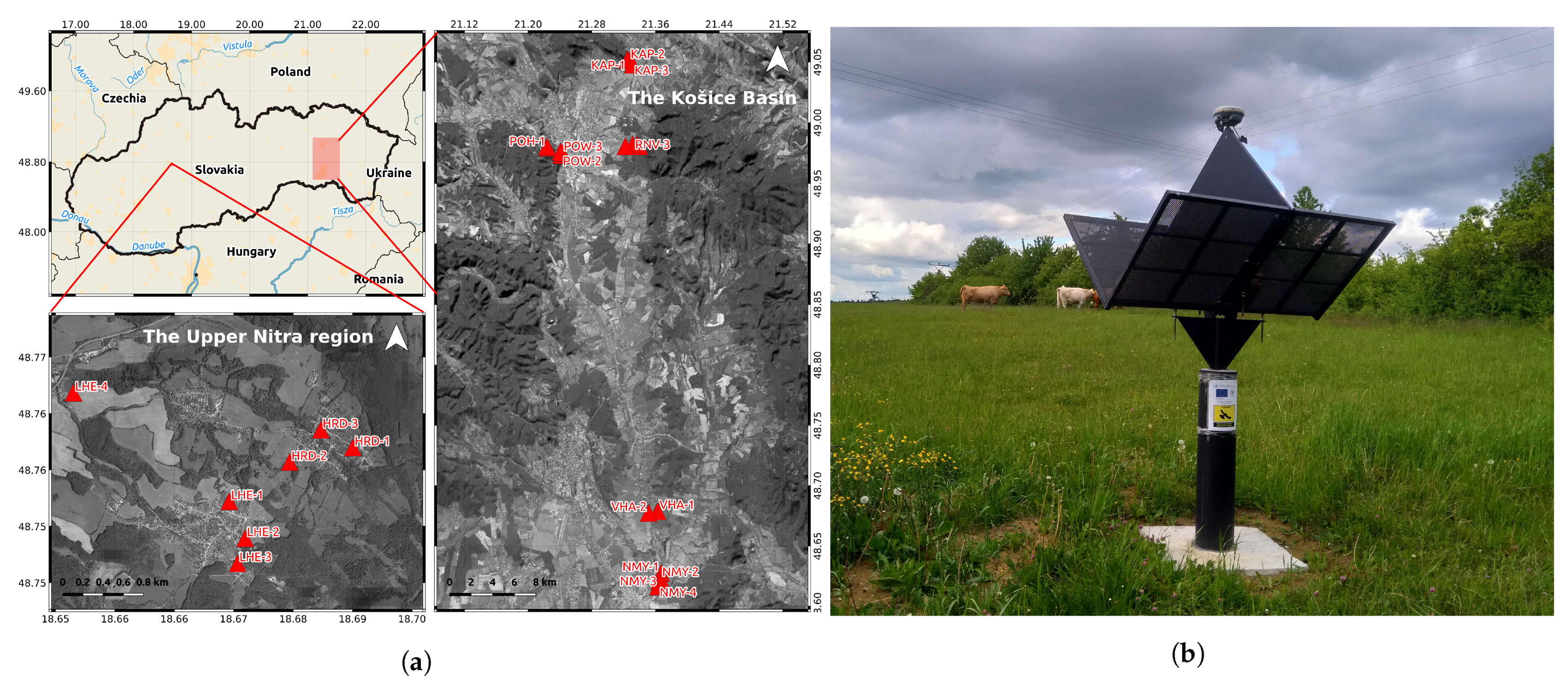
Three networks of corner reflectors (CR) were built for landslide activity monitoring in Slovakia (Figure 6) under the authority of the Slovakian State Geological Institute of Dionyz Stur (SGIDS). Seven CR are in The Upper Nitra region, six and ten CR are in the south and north of The Kosice Basin, see Figure 6a. The CR were deployed in February 2020. All CR are double back-flipped square trihedrals (DBST), that is, consisting of one reflector for ascending and one reflector for descending orbits, with inner-leg lengths of 0.76 m (Figure 6b). Reflectors are mounted on the drilled pillars, minimum 1 m above the ground, to minimize the undesired secondary ground reflections. The central plate of the DBST reflectors includes the mounting console for precise collocation with a geodetic GNSS antenna. Using back-flipped reflectors has an advantage of their bore-sight alignment (∼35.3° zenith angle) with the average local incidence angle of the Sentinel-1 IWS acquisitions (∼37.6°). DBST, being double reflectors, are oriented northwards with their central plate to minimize the unavoidable azimuth misalignment (approximately 11° for Central Europe) in ascending and descending directions. The drawback of a level back-flipped reflector is its proneness to precipitation or debris accumulation. Hence the design of DBST uses perforated aluminium side plates, with 5 mm hole diameter at 8 mm spacing. Given the geometry and orientation of the C-band Sentinel-1 measurements covering the case study areas, DBST yields an average analytical RCS of 33.5 dBm2.
Precise CR positions were measured by two, six-hour-long, static GNSS observation sessions using geodetic-grade Trimble receivers. The coordinates were determined in the ETRS89 (ETRF2000) system via the Slovakian permanent reference network SKPOS [64]. GNSS-derived coordinates refer to the reflector reference point, which is at the tip of the central plate (Figure 6b). For precise radar positioning, they are recomputed with respect to the phase centre, using local offsets known within the manufacturing accuracy of ∼2 mm.

4.1.1. Sentinel-1 Data

The Upper Nitra region CR are covered by the ascending orbit 175 and the descending orbit 51. The Kosice basin CR are covered by the ascending orbit 102 and the descending orbit 153. One year of time series (>60 SLC) from the period before the CR were deployed are used for the clutter estimation. Eleven months of CR time series are used for their performance testing and InSAR analysis. Altogether, four stacks are used, each comprising ∼120 SLC time series covering the period from February 2019 until December 2020.

4.1.2. Design Considerations

The primary purpose of our CR networks is landslide activity monitoring using InSAR. Therefore, individual CR were carefully placed to:
  • provide reliable displacement time series over the critical landslide zones,
  • strengthen the PS estimation network,
  • improve the positioning precision of the nearby PS,
  • provide an absolute geodetic reference for the InSAR displacement estimates.
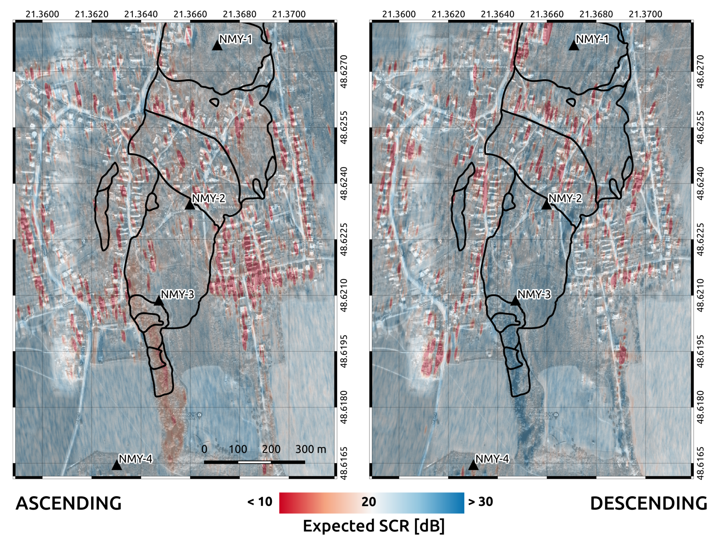
However, the limitations imposed by the radar clutter must be considered when choosing optimal locations for CR. It is particularly important for the InSAR CR, often installed in complex environments of the monitored deformation phenomena. Therefore, for planning purposes, the toolbox was used to produce maps of the expected SCR over the potential sites. These serve as initial guidance in the decision process of situating the CR. For a particular landslide in The Kosice basin, the average radar brightness of the clutter was estimated using one year of Sentinel-1 data. Expected SCR was computed using the DBST reflector’s analytical RCS of 33.5 dBm2. Figure 7 shows the map of the expected SCR over the area, superimposed on the orthoimage.
Using the simple thresholding approach, given the requirement on the LOS displacement standard deviation, σ d L O S , of <0.5 mm, the required SCR is >20 dB, see Equation (15). Hence all areas, which meet this condition and are separated at least two resolution cells in the range and azimuth directions from nearby point scatterers, can be considered viable for the CR. Nonetheless, it is strongly recommended to incorporate the in situ information into the decision process. Additionally, one has to be aware that the applied simulation does not consider the sensor’s thermal noise and other InSAR-related noises, such as the residual atmospheric phase or the unmodelled deformation. For areas with more significant clutter, reflector designs can be optimized, for example, utilizing larger dimensions to attain higher RCS and consequently higher SCR.

4.2. RCS Results

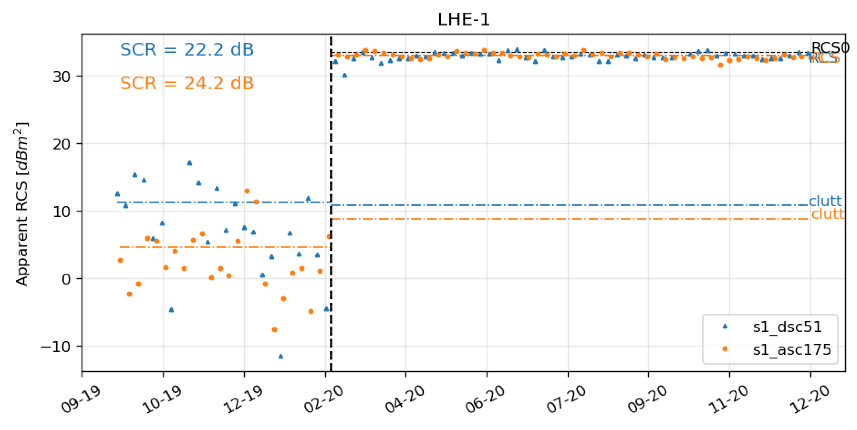
Once CR are permanently installed, the toolbox is used to assess their reflectivity performance on the Sentinel-1 SLC time series. Figure 8 shows the apparent RCS time series corresponding to a particular site of the DBST reflector. The dashed vertical line in the figure represents the date of the reflector deployment and proper bore-sight alignment. The horizontal lines denoted as RCS and clutt represent the estimated reflector’s temporal average RCS and the clutter power, respectively. The horizontal line, denoted as RCS0, represents the analytical RCS. The exact values are reported in Table 1.
For the CR at the LHE-1 station in Figure 8, we observe temporal average RCS of 33.00 dBm2 and 32.96 dBm2, from ascending and descending orbits, respectively. Low RCS standard deviations, 0.30 dBm2 and 0.37 dBm2, for ascending and descending orbits, respectively, confirm the temporal stability of the CR response. The clutter power, here expressed in dBm2 to be directly comparable to the reflector’s RCS, is independently estimated: (i) from the time series of the site before the CR deployment, (ii) from the time series of the CR, using the temporal SCR estimation method, see Section 3.6. We observe that the estimated clutter power remains practically unchanged after the CR installation. Therefore, we can reject the hypothesis on the presence of undesired secondary reflections, for example, from the ground or other proximate objects.
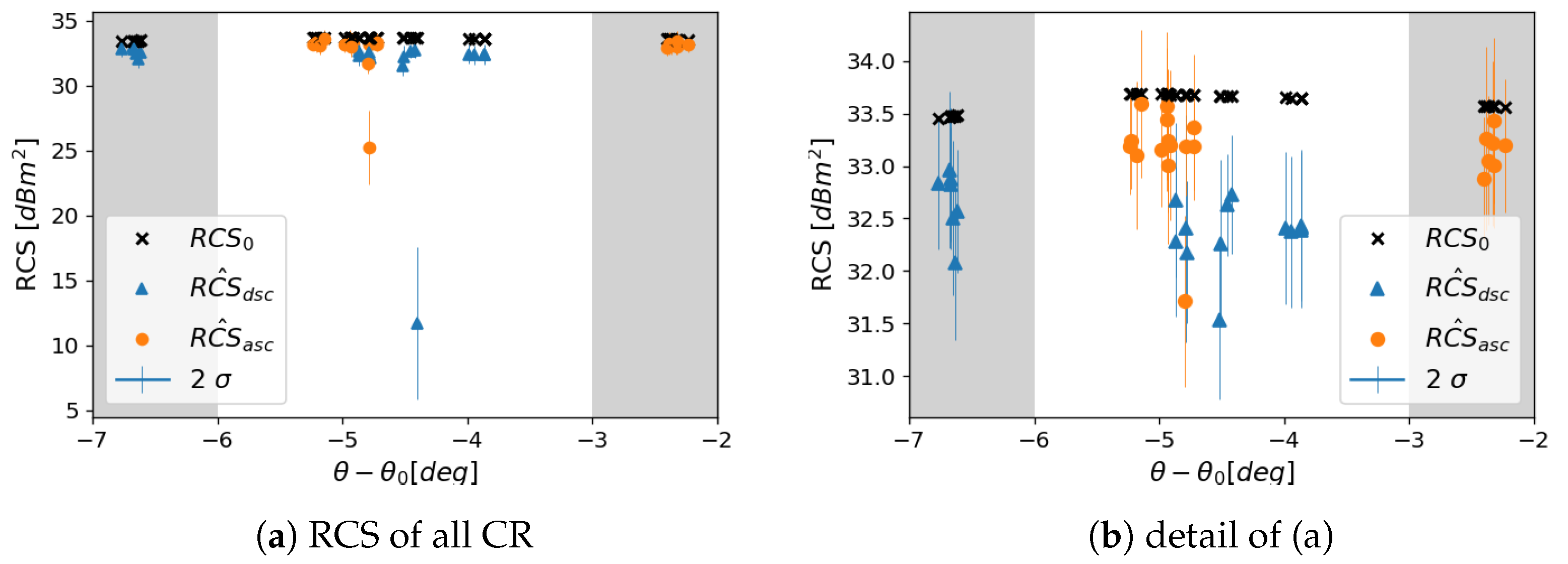
The estimated temporal average RCS of all corner reflectors in the network are shown in Figure 9a. Comparing the observed with the simulated RCS is used to evaluate the performance with respect to the design requirements. Only two CR—the ascending reflector POW-2, and the descending reflector RNV-1—show significantly lower average RCS. Upon in situ inspection, we found that it is caused by the uncontrolled, dense, and high vegetation growth in the bore-sight of the corresponding reflectors. Excluding these two problematic CR, the detailed RCS comparison is plotted again in Figure 9b. In the case of The Upper Nitra CR, corresponding to the two marginal gray areas in Figure 9, with zenith misalignment of −2.4 degrees and −6.8 degrees for ascending and descending orbits, respectively, the average RCS difference is −0.43 dB and −0.81 dB for ascending and descending orbits, respectively. In the case of The Kosice basin CR, corresponding to the central white area in Figure 9, with zenith misalignment of −5.1 degrees and −4.5 degrees for ascending and descending orbit, respectively, the average RCS difference is −0.51 dB and −1.29 dB for ascending and descending orbit, respectively. The differences are notably higher for the descending measurements, possibly indicating slight systematic azimuth misalignment of the CR.
Several other factors can negatively influence the observed RCS, mainly the mechanical construction imperfections [11]. For our particular case, the use of perforated side-plates could also have a negative impact. However, [12] reports insignificant RCS loss due to 1 cm diameter perforation at C-band. The radiometric stability of the Sentinel-1 A/B IWS SLC should be better than 0.25 dB [4,5]. Our average RCS standard deviation, excluding the problematic CR, is 0.33 dB and 0.37 dB for ascending and descending orbits, respectively. Considering the standard deviation of our RCS estimates, the idealized geometrical optics simulation, and the construction imperfections, we observe reasonable RCS differences, concluding that the DBST corner reflectors meet the design requirements.

4.3. SCR Results

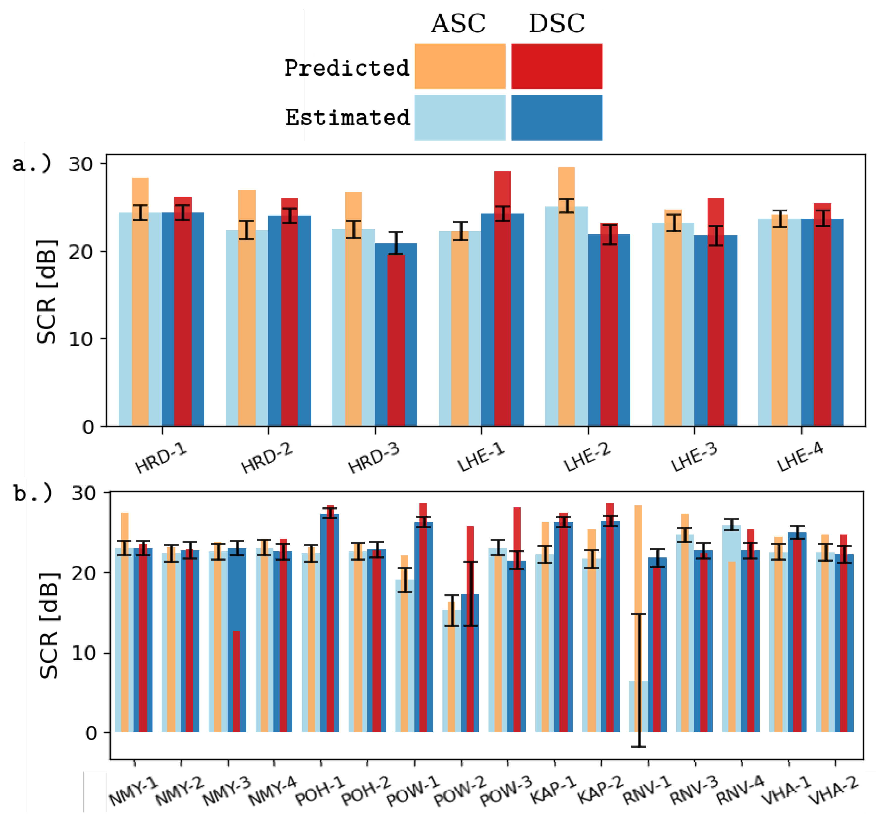
The average SCR of all corner reflectors were estimated using the temporal estimation method, see Section 3.6. Figure 10 shows the comparison of the estimated SCR and the predicted SCR per individual CR. The predicted SCR (in orange and red color) is the ratio of the corner reflector’s analytical RCS and the clutter power, estimated from the SLC time series of a particular site before the reflector installation. The estimated SCR is in light- and dark-blue color. The two-sigma confidence bounds of the estimated SCR are illustrated as black whiskers in the figure. For The Upper Nitra CR, the exact values are reported in Table 1.
Here, we test whether the corner reflector’s estimated SCR meets the monitoring expectations. Despite the varying differences of 1–3 dB between the estimated and the predicted SCR, The Upper Nitra reflectors (Figure 10a) all meet the monitoring requirements and attain the average SCR above 20 dB. Moreover, we observe very similar clutter levels for both acquisition geometries. In the case of The Kosice basin reflectors, the stations POW-2 and RNV-1 show significant differences for the descending and ascending orbits, respectively. For the RNV-1 station, the average SCR is as low as 6.4 dB. Hence, for the ascending reflector of this station, the required InSAR quality can not be guaranteed. As already seen on the average RCS estimates, see Figure 9a, it is caused by dense vegetation growth in the corresponding LOS directions, hence an inappropriate decision on the corner reflector placement. For other corner reflectors of the Kosice basin, the differences between the predicted and the estimated SCR are negligible in terms of our InSAR requirements.

4.4. Precise SAR Positioning Results

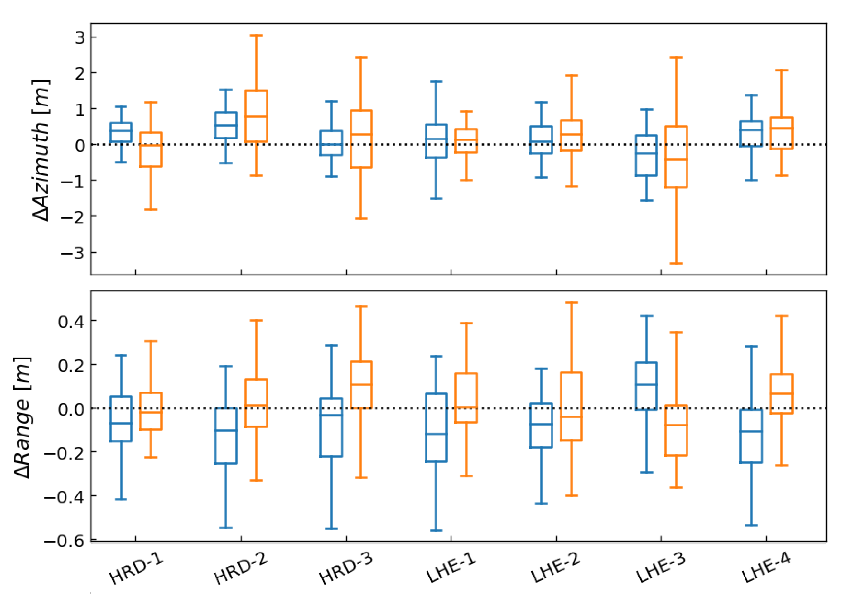
An independent way to verify the estimated SCR is to observe the reflector’s peak variance in the SLC time series and compare it to the variance predicted by the CRLB, see Equation (8). For this purpose, we use the Absolute Positioning Errors (APE), which are the azimuth/range differences between the GNSS-derived phase centre positions, corrected for all the systematic corrections listed in Section 3.3, and the observed sub-pixel peak positions (see Section 3.4). The APE boxplot for 7 CR in The Upper Nitra network, as generated by the toolbox, is shown in Figure 11. For 7 CR in The Upper Nitra, the average absolute positioning errors ± standard deviations are 13 ± 69 cm and −6 ± 18 cm in azimuth and range, respectively. The GNSS-derived CR coordinates have 2 cm horizontal accuracy and 4 cm vertical accuracy in the terrestrial reference frame.
Absolute positioning errors of the CR are generally used to quantify the SAR positioning accuracy of a particular sensor as performed by [10,33] for TerraSAR-X and Sentinel-1 missions. Absolute positioning accuracy of the Sentinel-1 IWS products reported by [10,33] and regular Sentinel-1 calibration reports [4,5] is −20 ± 27 cm and −10 ± 7 cm for the range and azimuth directions of Sentinel-1A, respectively, and 14 ± 23 cm and 3 ± 6 cm for the range and azimuth directions of Sentinel-1B, respectively. These are determined using the Australian Corner Reflector Array, DLR corner reflectors, and transponders.
For our particular application, to independently validate the estimated SCR of the CR, we do the reverse and use the observed position variance to compare with the prediction computed by the SCR estimated in Section 4.3. The comparison of the observed APE and CRLB predictions are listed in Table 2. The reported APE are mean ± standard deviation.
The average range APE for the ascending orbit is at the accuracy level of the GNSS coordinates. However, we observe −10 cm systematic shift in the range direction for the descending orbit. Nonetheless, similar offsets are reported by [10,33]. Moreover, we do not distinguish between Sentinel-1A and B. While the azimuth APE standard deviations nicely match the CRLB predictions, the range APE standard deviations are almost exactly a factor 2 higher. It is a consequence of other errors, such as variations in tropospheric signal delay, which could not be completely mitigated by the ERA5 ECMWF model with limited spatial and temporal resolution.
To conclude, the toolbox provides the geodetic-grade positioning of the reflectors. However, for absolute positioning in the terrestrial reference frame, the third dimension, cross-range, is limited by the accuracy of InSAR [18]. The APE analysis is also useful for identifying gross errors, such as mistakenly selecting different nearby point scatterers during the peak extraction procedure.

4.5. InSAR Results

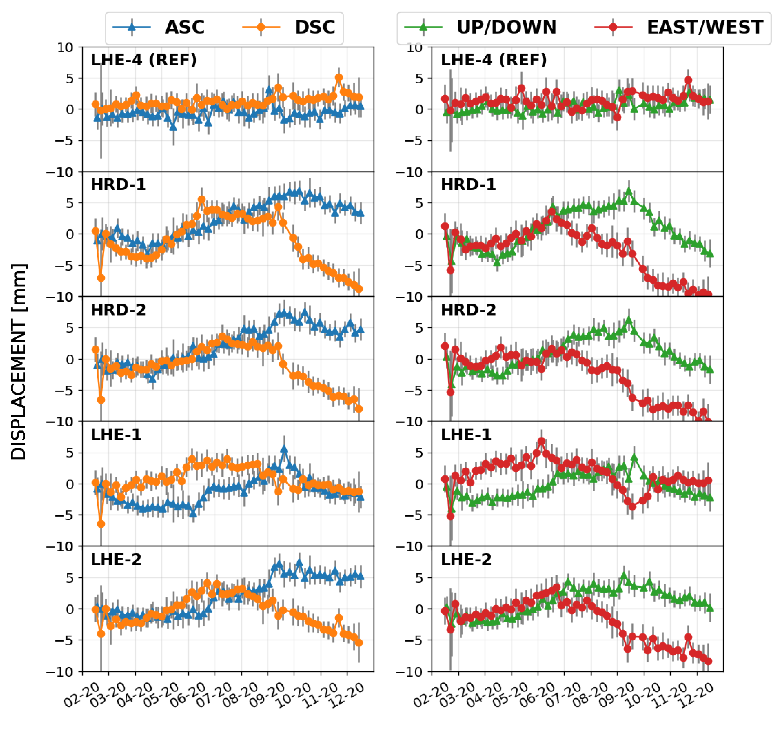
The time series InSAR analysis of the corner reflectors was performed jointly with the surrounding highly coherent PS, following the procedure described in Section 3.7. InSAR results from The Upper Nitra CR network, monitoring the active landslide, are presented. To verify the stability of the reference CR (LHE-4), we present the results of the datum-free network solution. Estimated displacement time series are shown in Figure 12. The error bars correspond to the two-sigma intervals given by the estimated SCR and scaled by the variance factors of individual acquisitions. The phase centre offset between the ascending and descending reflectors of the DBST is only 2 cm in the longitudinal direction. Therefore, we can safely assume that both reflectors undergo the same displacement. Assuming the temporal smoothness of the displacement between the nearest acquisitions, which are less than 72 h apart, we can directly do the decomposition of the LOS displacements into the vertical and horizontal components, using Equation (17).
The estimated CR displacement time series reveal strongly nonlinear motions. The displacement time series in the horizontal direction reveal predominantly west-ward motion, which is in agreement with the slope orientation of the landslide, as already reported by [47,65]. However, the precise displacement time series in Figure 12 also reveal seasonal effects and periods of acceleration. The seasonal effect, that is, few millimeters of uplift following winter 2019/20, could be the consequence of the extrusion of the pillars carrying the CR, as this effect is not so apparent on the nearby PS. The displacement acceleration in September/October 2020 follows periods of significant precipitation, confirming the landslide’s reaction to the underground water accumulation [47,66].
Since CR exhibit a nonlinear displacement behaviour, we have interpolated the time series by the cubic splines, assuming that the model residuals are representative of the phase noise. The number of splines (1–3), fitted to the equal temporal subsets, was determined by satisfying the Minimum Description Length criterion [67]. The standard deviations of the model residuals vary between 0.6–0.9 mm for the ascending orbit and between 0.7 mm–1.3 mm for the descending orbit. These are more than a factor 2 higher than the theoretical values predicted via the estimated SCR, see Table 1. However, the imperfect atmospheric phase screen mitigation also increases the time series variance. Moreover, external effects, such as wind loading, may impair the reflector’s stability.

5. Discussion and Conclusions

We show the practical use of the GECORIS toolbox by analyzing the Sentinel-1 SAR time series of corner reflector networks intended for InSAR monitoring of landslides. We demonstrate that simulating SCR over the sites of interest before corner reflector deployment is a valuable aid in a network design. SCR can be, in most cases, predicted with sufficient accuracy. We assess the RCS and SCR of individual corner reflectors against the design requirements, and we successfully identify two problematic reflectors. Locations of the InSAR corner reflectors are determined primarily by the monitored deformation phenomena, often at the cost of suboptimal clutter conditions. Moreover, we show that the toolbox can attain the geodetic positioning precision of corner reflectors. Finally, the nonlinear InSAR displacement time series of each corner reflector were estimated with sub-millimeter precision, meeting the imposed network design requirements.
Since GECORIS is an efficient toolbox working only on the SAR image patches containing reflectors, regular updates can be performed as soon as a recent Sentinel-1 acquisition is available. It requires only the station log files to produce all results in a JSON format accompanied by various plots shown in the previous chapter. Therefore, it allows tracking the corner reflector’s measurement quality and operationally identifying possible problems, for example, reflector damage or debris accumulation. Using the GECORIS, even less-experienced users from wider geodetic, SAR and InSAR communities can readily analyze SAR time series of their corner reflectors in a standard and concise way. We consider this tool especially useful in the context of emerging national and international initiatives, installing artificial radar reflectors, collocated with continuously operating GNSS reference stations, to provide an absolute geodetic reference for large-scale, big-data, InSAR analysis.
The GECORIS toolbox is open-source and modular, therefore many potential extensions could be implemented. Here, we list the most notable:
  • Support for other current SAR missions (e.g., Radarsat-2, TerraSAR-X).
  • Support for corner reflectors of arbitrary shapes as well as radar transponders.
  • Inclusion of repeated GNSS measurements of corner reflectors as auxiliary information to assist the spatio-temporal ambiguity resolution within the InSAR processing.
  • The first-order InSAR network, consisting of corner reflectors and high-quality PS, can be readily densified using additional PS [38] or distributed scatterers with a reconstructed single-master phase [39].
  • Incorporating a corner reflector as a PS with known absolute position in the TRF, fixing the relative height estimates of the nearby PS [18].
  • Transformation of the InSAR datum-free network solution into the terrestrial reference frame using S-transformation [13,68].

Author Contributions

Conceptualization, R.C. and H.v.d.M.; Data curation, R.C. and J.P.; Formal analysis, R.C.; Funding acquisition, J.P.; Investigation, R.C.; Methodology, R.C. and H.v.d.M.; Resources, R.C. and J.P.; Software, R.C.; Validation, R.C.; Visualization, R.C.; Writing—original draft, R.C.; Writing—review & editing, R.C. and H.v.d.M. All authors have read and agreed to the published version of the manuscript.

Funding

This research received no external funding.

Institutional Review Board Statement

Not applicable.

Informed Consent Statement

Not applicable.

Data Availability Statement

The GECORIS toolbox is available as a public repository at: https://bitbucket.org/memorid/gecoris (accessed on 22 February 2021).

Acknowledgments

Corner reflectors employed in this study were built thanks to the Slovakian geological task ‘Monitoring of landslide deformations’, which is solved within the Environmental Quality Operational Program, priority axis 3: Support of risk management, emergency management and resilience to emergencies affected by climate change, which is directly related to the task CMS–GF. The work in this paper was also accomplished with the support from the grant by the Slovak APVV agency by means of the project APVV-19-0150.

Conflicts of Interest

The authors declare no conflict of interest.

Abbreviations

The following abbreviations are used in this manuscript:
FOSSFree and Open-Source Software
CRCorner Reflector/Reflectors
SARSynthetic Aperture Radar
InSARInterferometric Synthetic Aperture Radar
RCSRadar Cross Section
SCRSignal-to-Clutter Ratio
TRFTerrestrial Reference Frame
ITRSInternational Terrestrial Reference System
ETRS89European Terrestrial Reference System
ITRFInternational Terrestrial Reference Frame
SETSolid Earth Tides
PSPoint Scatterer
GNSSGlobal Navigation Satellite Systems
IRFImpulse Response Function
SLCSingle Look Complex
IWSInterferometric Wide Swath
LOSLine-of-Sight
DBSTDouble Back-flipped Square Trihedral
PRFPulse Repetition Frequency
RSRRange Sampling Rate
CRLBCramer-Rao Lower Bound
APSAtmospheric Phase Screen
SNAPSentinels Application Platform
IGSInternational GNSS Service
EUREFReference Frame Subcommission for Europe
ECMWFEuropean Centre for Medium-Range Weather Forecasts
TECTotal Electron Content
TOPSTerrain Observation with Progressive Scan
MADMedian Absolute Deviation
VCEVariance Component Estimation
APEAbsolute Positioning Error
DLRDeutsches Zentrum für Luft

References

  1. Freeman, A. SAR calibration: An overview. IEEE Trans. Geosci. Remote Sens. 1992, 30, 1107–1121. [Google Scholar] [CrossRef]
  2. Gray, A.; Vachon, P.; Livingstone, C.; Lukowski, T. Synthetic aperture radar calibration using reference reflectors. IEEE Trans. Geosci. Remote Sens. 1990, 28, 374–383. [Google Scholar] [CrossRef]
  3. Doerry, A.W. Reflectors for SAR Performance Testing; Technical Report; Sandia National Laboratories: Albuquerque, NM, USA; Livermore, CA, USA, 2008.
  4. CLS. Sentinel-1A N-Cyclic Performance Report—2020-07; Technical Report 7; Collecte Localisation Satellites (CLS): Ramonville Saint-Agne, France, 2020. [Google Scholar]
  5. CLS. Sentinel-1B N-Cyclic Performance Report—2020-07; Technical Report 7; Collecte Localisation Satellites (CLS): Ramonville Saint-Agne, France, 2020. [Google Scholar]
  6. Prati, C.; Rocca, F.; Monti Guarnieri, A. SAR interferometry experiments with ERS-1. In Proceedings of the First ERS-1 Symposium—Space at the Service of our Environment, Cannes, France, 4–6 November 1992; pp. 211–217. [Google Scholar]
  7. Marinkovic, P.; Ketelaar, V.; van Leijen, F.; Hanssen, R. InSAR Quality Control: Analysis of Five Years of Corner Reflector Time Series. In Proceedings of the Fifth International Workshop on ERS/Envisat SAR Interferometry, ‘FRINGE07’, Frascati, Italy, 26–30 November 2007; Lacoste, H., Ouwehand, L., Eds.; ESA Communication Production Office: Noordwijk, The Netherlands, 2008; pp. 1–8. [Google Scholar]
  8. Schubert, A.; Miranda, N.; Geudtner, D.; Small, D. Sentinel-1A/B Combined Product Geolocation Accuracy. Remote Sens. 2017, 9, 607. [Google Scholar] [CrossRef] [Green Version]
  9. Balss, U.; Gisinger, C.; Eineder, M.; Breit, H.; Schubert, A.; Small, D. Survey Protocol for Geometric SAR Sensor Analysis; Technical Report; German Aerospace Center (DLR), Technical University of Munich (TUM), Remote Sensing Laboratories—University of Zurich (RSL): Oberpfaffenhofen, Germany, 2018. [Google Scholar]
  10. Gisinger, C.; Schubert, A.; Breit, H.; Garthwaite, M.; Balss, U.; Willberg, M.; Small, D.; Eineder, M.; Miranda, N. In-Depth Verification of Sentinel-1 and TerraSAR-X Geolocation Accuracy Using the Australian Corner Reflector Array. IEEE Trans. Geosci. Remote Sens. 2020, 1–28. [Google Scholar] [CrossRef]
  11. Garthwaite, M.C. On the Design of Radar Corner Reflectors for Deformation Monitoring in Multi-Frequency InSAR. Remote Sens. 2017, 9, 648. [Google Scholar] [CrossRef] [Green Version]
  12. Jauvin, M.; Yan, Y.; Trouvé, E.; Fruneau, B.; Gay, M.; Girard, B. Integration of Corner Reflectors for the Monitoring of Mountain Glacier Areas with Sentinel-1 Time Series. Remote Sens. 2019, 11, 988. [Google Scholar] [CrossRef] [Green Version]
  13. Mahapatra, P.; van der Marel, H.; van Leijen, F.; Samiei Esfahany, S.; Klees, R.; Hanssen, R. InSAR datum connection using GNSS-augmented radar transponders. J. Geod. 2017. [Google Scholar] [CrossRef] [Green Version]
  14. Bamler, R.; Hartl, P. Synthetic aperture radar interferometry. Inverse Probl. 1998, 14, R1–R54. [Google Scholar] [CrossRef]
  15. Cumming, I.G.; Wong, F.H. Digital Processing of Synthetic Aperture Radar Data: Algorithms and Implementation; Artech House: London, UK, 2005; Volume 1. [Google Scholar]
  16. Dheenathayalan, P.; Small, D.; Schubert, A.; Hanssen, R.F. High-precision positioning of radar scatterers. J. Geod. 2016, 90, 403–422. [Google Scholar] [CrossRef] [Green Version]
  17. Gisinger, C.; Willberg, M.; Balss, U.; Klügel, T.; Mähler, S.; Pail, R.; Eineder, M. Differential geodetic stereo SAR with TerraSAR-X by exploiting small multi-directional radar reflectors. J. Geod. 2016, 91. [Google Scholar] [CrossRef]
  18. Yang, M.; López-Dekker, P.; Dheenathayalan, P.; Liao, M.; Hanssen, R.F. On the value of corner reflectors and surface models in InSAR precise point positioning. ISPRS J. Photogramm. Remote Sens. 2019, 158, 113–122. [Google Scholar] [CrossRef]
  19. Dheenathayalan, P.; Cuenca, M.C.; Hoogeboom, P.; Hanssen, R.F. Small reflectors for ground motion monitoring with InSAR. IEEE Trans. Geosci. Remote Sens. 2017, 55, 6703–6712. [Google Scholar] [CrossRef]
  20. Bamler, R.; Eineder, M. Accuracy of differential shift estimation by correlation and split-bandwidth interferometry for wideband and delta-k SAR systems. IEEE Geosci. Remote Sens. Lett. 2005, 2, 151–155. [Google Scholar] [CrossRef]
  21. Garthwaite, M.C.; Nancarrow, S.; Hislop, A.; Thankappan, M.; Dawson, J.H.; Lawrie, S. The Design of Radar Corner Reflectors for the Australian Geophysical Observing System: A Single Design Suitable for InSAR Deformation Monitoring and SAR Calibration at Multiple Microwave Frequency Bands; Technical Report; Geoscience Australia: Canberra, Australia, 2015. [CrossRef]
  22. Hanssen, R.F. A Radar Retroreflector Device and a Method of Preparing a Radar Retroreflector Device. WO/2018/236215, 27 December 2018. [Google Scholar]
  23. Kamphuis, J. Co-Location of Geodetic Reference Points. Master’s Thesis, TU Delft Civil Engineering and Geoscience, Delft, The Netherlands, 2019. [Google Scholar]
  24. Raney, R.K.; Freeman, T.; Hawkins, R.W.; Bamler, R. A plea for radar brightness. In Proceedings of the IGARSS’94—1994 IEEE International Geoscience and Remote Sensing Symposium, Pasadena, CA, USA, 8–12 August 1994; Volume 2, pp. 1090–1092. [Google Scholar]
  25. Radiometric Calibration of S-1 Level-1 Products Generated by the S-1 IPF; ESA-EOPG-CSCOP-TN-0002. Technical Report. 2015. Available online: https://sentinel.esa.int/documents/247904/685163/S1-Radiometric-Calibration-V1.0.pdf (accessed on 22 February 2021).
  26. Skolnik, M. Introduction to Radar Systems; Electrical Engineering Series; McGraw-Hill: Singapore, 2001. [Google Scholar]
  27. Schmidt, K.; Schwerdt, M.; Miranda, N.; Reimann, J. Radiometric Comparison within the Sentinel-1 SAR Constellation over a Wide Backscatter Range. Remote Sens. 2020, 12, 854. [Google Scholar] [CrossRef] [Green Version]
  28. Ulander, L.M. Accuracy of Using Point Targets for SAR Calibration. IEEE Trans. Aerosp. Electron. Syst. 1991, 27, 139–148. [Google Scholar] [CrossRef]
  29. Czikhardt, R.; van der Marel, H.; van Leijen, F.J.; Hanssen, R.F. Estimating Signal-to-Clutter Ratio of InSAR Corner Reflectors from SAR Time Series. IEEE Geosci. Remote Sens. Lett. 2021. submitted. [Google Scholar]
  30. Groot, J. Letter: Cross Section Computation of Trihedral Corner Reflectors with the Geometrical Optics Approximation. Eur. Trans. Telecommun. 1992, 3, 637–642. [Google Scholar] [CrossRef]
  31. Qin, Y.; Perissin, D.; Lei, L. The Design and Experiments on Corner Reflectors for Urban Ground Deformation Monitoring in Hong Kong. Int. J. Antennas Propag. 2013, 2013. [Google Scholar] [CrossRef] [Green Version]
  32. Van der Marel, H.; van Leijen, F.J.; Hanssen, R.F. First Analysis of C-Band ECR Transponders for Insar Geodesy. In Proceedings of the IGARSS 2018—2018 IEEE International Geoscience and Remote Sensing Symposium, Valencia, Spain, 22–27 July 2018; pp. 1399–1402. [Google Scholar] [CrossRef] [Green Version]
  33. Guide to Sentinel-1 Geocoding; Technical Report; Remote Sensing Laboratories—University of Zurich (RSL). 2019. Available online: https://sentinel.esa.int/documents/247904/1653442/Guide-to-Sentinel-1-Geocoding.pdf (accessed on 22 February 2021).
  34. Yang, M.; Dheenathayalan, P.; López-Dekker, P.; van Leijen, F.; Liao, M.; Hanssen, R.F. On the influence of sub-pixel position correction for PS localization accuracy and time series quality. ISPRS J. Photogramm. Remote Sens. 2020, 165, 98–107. [Google Scholar] [CrossRef]
  35. Balss, U.; Gisinger, C.; Eineder, M. Measurements on the Absolute 2-D and 3-D Localization Accuracy of TerraSAR-X. Remote Sens. 2018, 10, 656. [Google Scholar] [CrossRef] [Green Version]
  36. Ferretti, A.; Prati, C.; Rocca, F. Permanent Scatterers in SAR Interferometry. IEEE Trans. Geosci. Remote Sens. 2001, 39, 8–20. [Google Scholar] [CrossRef]
  37. Hanssen, R.F. Radar Interferometry: Data Interpretation and Error Analysis; Springer: Berlin/Heidelberg, Germany, 2001; Volume 2. [Google Scholar]
  38. Van Leijen, F.J. Persistent Scatterer Interferometry Based on Geodetic Estimation Theory; NCG: Amersfoort, The Netherlands, 2014. [Google Scholar]
  39. Ansari, H.; De Zan, F.; Bamler, R. Efficient Phase Estimation for Interferogram Stacks. IEEE Trans. Geosci. Remote Sens. 2018, 56, 4109–4125. [Google Scholar] [CrossRef]
  40. Hu, F.; Wu, J.; Chang, L.; Hanssen, R. Incorporating Temporary Coherent Scatterers in Multi-Temporal InSAR Using Adaptive Temporal Subsets. IEEE Trans. Geosci. Remote Sens. 2019, 1–13. [Google Scholar] [CrossRef] [Green Version]
  41. Kampes, B.M.; Hanssen, R.F. Ambiguity Resolution for Permanent Scatterer Interferometry. IEEE Trans. Geosci. Remote Sens. 2004, 42, 2446–2453. [Google Scholar] [CrossRef] [Green Version]
  42. ESA. Sentinel Application Platform (SNAP). Available online: https://step.esa.int/main/toolboxes/snap/ (accessed on 22 February 2021).
  43. IGS. International GNSS Service. Available online: http://www.igs.org/ (accessed on 22 February 2021).
  44. EUREF. Reference Frame Sub-Commission for Europe. Available online: http://www.euref.eu (accessed on 22 February 2021).
  45. Sansosti, E.; Berardino, P.; Manunta, M.; Serafino, F.; Fornaro, G. Geometrical SAR image registration. IEEE Trans. Geosci. Remote Sens. 2006, 44, 2861–2870. [Google Scholar] [CrossRef]
  46. Prats-Iraola, P.; Scheiber, R.; Marotti, L.; Wollstadt, S.; Reigber, A. TOPS Interferometry With TerraSAR-X. IEEE Trans. Geosci. Remote Sens. 2012, 50, 3179–3188. [Google Scholar] [CrossRef] [Green Version]
  47. Czikhardt, R.; Papco, J.; Bakon, M.; Liscak, P.; Ondrejka, P.; Zlocha, M. Ground Stability Monitoring of Undermined and Landslide Prone Areas by Means of Sentinel-1 Multi-Temporal InSAR, Case Study from Slovakia. Geosciences 2017, 7, 87. [Google Scholar] [CrossRef] [Green Version]
  48. Peter, H.; Jäggi, A.; Fernández, J.; Escobar, D.; Ayuga, F.; Arnold, D.; Wermuth, M.; Hackel, S.; Otten, M.; Simons, W.; et al. Sentinel-1A—First precise orbit determination results. Adv. Space Res. 2017, 60, 879–892. [Google Scholar] [CrossRef]
  49. EUREF Technical Note 1: Relationship and Transformation between the International and the European Terrestrial Reference Systems. Technical Report. 2018. Available online: http://etrs89.ensg.ign.fr/pub/EUREF-TN-1.pdf (accessed on 22 February 2021).
  50. IERS. International Earth Rotation and Reference Systems Service. Available online: https://www.iers.org/ (accessed on 22 February 2021).
  51. Hersbach, H.; Dee, D. ERA5 reanalysis is in production. ECMWF Newsl. 2016, 147, 5–6. [Google Scholar]
  52. Hu, Z.; Mallorquí, J.J. An Accurate Method to Correct Atmospheric Phase Delay for InSAR with the ERA5 Global Atmospheric Model. Remote Sens. 2019, 11, 1969. [Google Scholar] [CrossRef] [Green Version]
  53. CLS. Sentinel-1 Level 1 Detailed Algorithm Definition; Technical Report; Collecte Localisation Satellites (CLS): Ramonville Saint-Agne, France, 2019. [Google Scholar]
  54. Yague-Martinez, N.; De Zan, F.; Prats-Iraola, P. Coregistration of Interferometric Stacks of Sentinel-1 TOPS Data. IEEE Geosci. Remote Sens. Lett. 2017, 14, 1002–1006. [Google Scholar] [CrossRef] [Green Version]
  55. Definition of the TOPS SLC Deramping Function for Products Generated by the S-1 IPF, 3rd ed.; European Space Agency: Paris, France, 2017; Available online: https://earth.esa.int/documents/247904/1653442/Sentinel-1-TOPS-SLC_Deramping (accessed on 22 February 2021).
  56. Leys, C.; Ley, C.; Klein, O.; Bernard, P.; Licata, L. Detecting outliers: Do not use standard deviation around the mean, use absolute deviation around the median. J. Exp. Soc. Psychol. 2013, 49, 764–766. [Google Scholar] [CrossRef] [Green Version]
  57. Ketelaar, G.; Marinkovic, P.; Hanssen, R. Validation of point scatterer phase statistics in multi-pass InSAR. In Proceedings of the CEOS SAR Workshop, Ulm, Germany, 27–28 May 2004; pp. 27–28. [Google Scholar]
  58. Chum, O.; Philbin, J.; Zisserman, A. Near duplicate image detection: Min-Hash and tf-idf weighting. In Proceedings of the 19th British Machine Vision Conference (BMVC 2008), Leeds, UK, 1–4 September 2008; pp. 812–815. [Google Scholar]
  59. Perissin, D. SAR Super-Resolution and Characterization of Urban Targets: An Advanced Analysis on the Physical Nature of Synthetic Aperture Radar Permanent Scatterers through ERS and Envisat Interferometry; VDM Verlag Dr. Müller: Saarbrücken, Germany, 2010. [Google Scholar]
  60. Teunissen, P.J.G.; Amiri-Simkooei, A.R. Least-squares variance component estimation. J. Geod. 2008, 82, 65–82. [Google Scholar] [CrossRef] [Green Version]
  61. Teunissen, P.J.G. Least-Squares Estimation of the Integer GPS Ambiguities: LRS Series 6; Technical Report; Delft Geodetic Computing Centre, Delft University of Technology: Delft, The Netherlands, 1993. [Google Scholar]
  62. Kampes, B.M. Radar Interferometry: Persistent Scatterer Technique; Springer: Berlin/Heidelberg, Germany, 2006. [Google Scholar]
  63. Ketelaar, V.B.H.G. Satellite Radar Interferometry: Subsidence Monitoring Techniques; Springer: Assen, The Netherlands, 2009. [Google Scholar] [CrossRef]
  64. SKPOS. Slovak Real Time Positioning Service. Available online: http://www.skpos.gku.sk/en/ (accessed on 22 February 2021).
  65. Bakon, M.; Czikhardt, R.; Papco, J.; Barlak, J.; Rovnak, M.; Adamisin, P.; Perissin, D. remotIO: A Sentinel-1 Multi-Temporal InSAR Infrastructure Monitoring Service with Automatic Updates and Data Mining Capabilities. Remote Sens. 2020, 12, 1892. [Google Scholar] [CrossRef]
  66. Ondrejka, P.; Bakon, M.; Papco, J.; Liscak, P. Monitoring of sliding activity of the territory Prievidza-Hradec. Geotechnika 2016, 2016, 3–12, (In Slovak with English summary). [Google Scholar]
  67. Barzaghi, R.; Reguzzoni, M.; De Gaetani, C.; Caldera, S.; Rossi, L. Cultural Heritage Monitoring by Low-cost GNSS Receivers: A Feasibility Study for San Gaudenzio’s Cupola, Novara. ISPRS Int. Arch. Photogramm. Remote Sens. Spat. Inf. Sci. 2019, XLII-2/W11, 209–216. [Google Scholar] [CrossRef] [Green Version]
  68. Teunissen, P. Zero order design: Generalized inverses, adjustment, the datum problem and S-transformations. In Optimization and Design of Geodetic Networks; Springer: Berlin/Heidelberg, Germany, 1985; pp. 11–55. [Google Scholar]
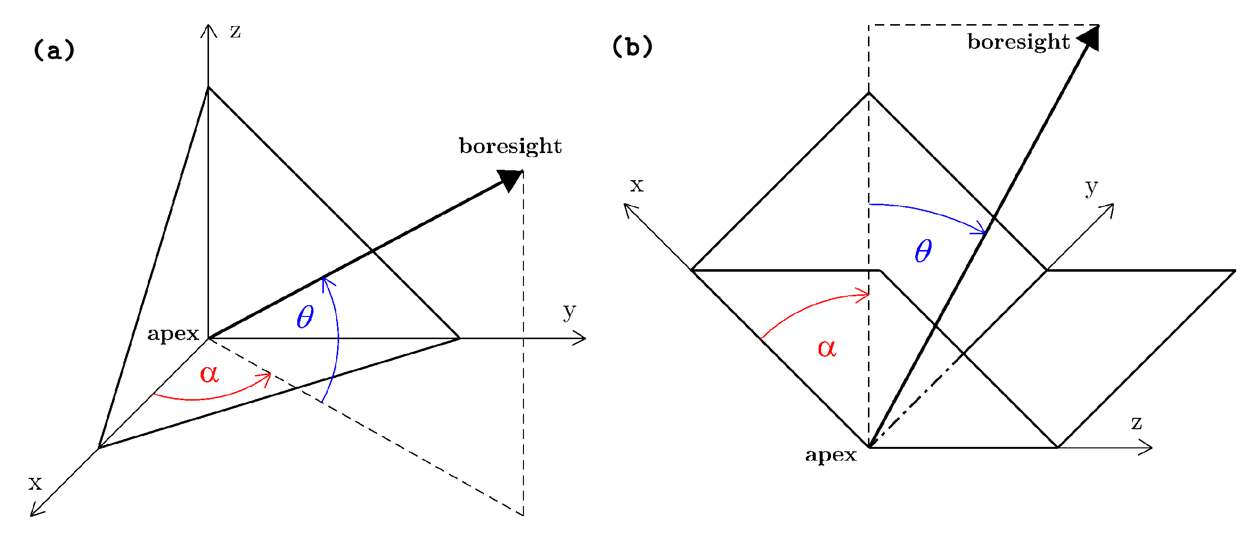
Figure 1. The geometry of (a) a triangular and (b) square back-flipped (right) trihedral corner reflectors.
Remotesensing 13 00926 g001
Figure 2. (a) Off-bore-sight attenuation (Radar Cross Section loss) of a back-flipped square trihedral reflector, (b) simulated Radar Cross Section (RCS) of a triangular and square trihedrals w.r.t. inner-leg length and effect of their misalignment. DBST indicates values for double back-flipped squre trihedral reflectors employed within our case study.
Remotesensing 13 00926 g002
Figure 3. Flowchart of the Geodetic Corner Reflector (In)SAR (GECORIS) toolbox.
Remotesensing 13 00926 g003
Figure 4. The impact of the individual SAR positioning corrections at the double corner reflector with 22 dB Signal-to-Clutter Ratio (SCR). Each scatter represents a single Sentinel-1 acquisition.
Remotesensing 13 00926 g004
Figure 5. An example of the oversampling impact on the corner reflector’s impulse response peak extraction in the Sentinel-1 Interferometric Wide Swath (IWS) Single Look Complex (SLC) data.
Remotesensing 13 00926 g005
Figure 6. (a) Three networks of 23 double back-flipped square-trihedral (DBST) corner reflectors (red triangles) in The Upper Nitra region and The Kosice Basin, Slovakia. (b) Photo of the DBST reflector with the collocated GNSS receiver.
Remotesensing 13 00926 g006
Figure 7. Maps of the expected Signal-to-Clutter Ratio (SCR) for a particular landslide area before the corner reflectors (CR) were installed. Black polygons demarcate the active landslide. Black triangles signify the final CR locations. Maps are superimposed on the orthoimage, ©GKU, NLC; y. 2017–2019.
Remotesensing 13 00926 g007
Figure 8. Apparent Radar Cross Section (RCS) time series of the site of the DBST reflector installed in February 2020 (the dashed vertical line).
Remotesensing 13 00926 g008
Figure 9. Estimated vs. analytical RCS (RCS0) of the corner reflectors (CR) in The Upper Nitra (gray areas) and The Kosice basin (white area) plotted w.r.t. their zenith misalignment.
Remotesensing 13 00926 g009
Figure 10. Predicted versus estimated average SCR of the DBST corner reflectors in the Upper Nitra, (a), and the Kosice basin, (b). Orange (ascending) and red (descending) bars correspond to the SCR predicted using the clutter power estimated from the sites’ measurements before the reflectors were installed. Light-blue (ascending) and dark-blue (descending) bars correspond to the average SCR estimated from the time series of the reflectors.
Remotesensing 13 00926 g010
Figure 11. Boxplot of the Absolute Positioning Errors (APE) of the CR in The Upper Nitra.
Remotesensing 13 00926 g011
Figure 12. InSAR displacement time series of the corner reflectors at the Upper Nitra landslide. Each row corresponds to an individual DBST reflector. Left column corresponds to the Line-of-sight (LOS) displacements and right column corresponds to the vertical and horizontal displacements.
Remotesensing 13 00926 g012
Table 1. Summary of the Radar Cross Section (RCS) and Signal-to-Clutter Ratio (SCR) results for corner reflectors (CR) in The Upper Nitra region.
CRSentinel-1RCS [dBm2] σ ^ RCS SCR [dB] σ d LOS CRLB
TrackPredic.Estim.[dBm2]Predic.Estim.[mm]
HRD-1ASC17533.5732.880.2926.6924.420.27
DSC5133.4832.570.2928.3024.270.27
HRD-2ASC17533.5733.050.3125.7823.970.28
DSC5133.4732.500.3726.8722.350.34
LHE-1ASC17533.5733.000.3027.9024.180.28
DSC5133.4732.960.3724.6522.200.35
LHE-2ASC17533.5733.220.3923.1421.740.37
DSC5133.4732.830.2728.6625.050.25
LHE-4ASC17533.5733.190.3225.3823.680.29
DSC5133.4732.840.3223.9723.610.29
Table 2. Summary of the positioning accuracy for corner reflectors in The Upper Nitra.
CRSentinel-1Azimuth [m]Range [m]
trackCRLBAPECRLBAPE
HRD-1ASC1750.51−0.21 ± 0.760.07−0.02 ± 0.16
DSC510.520.19 ± 0.500.08−0.08 ± 0.16
HRD-2ASC1750.540.64 ± 0.720.08−0.02 ± 0.14
DSC510.650.44 ± 0.560.10−0.12 ± 0.18
LHE-1ASC1750.530.12 ± 0.570.070.03 ± 0.18
DSC510.660.29 ± 0.890.11−0.15 ± 0.20
LHE-2ASC1750.700.31 ± 0.740.10−0.02 ± 0.21
DSC510.470.06 ± 0.580.08−0.10 ± 0.16
LHE-4ASC1750.560.38 ± 0.660.080.02 ± 0.19
DSC510.560.17 ± 0.620.09−0.13 ± 0.17
Publisher’s Note: MDPI stays neutral with regard to jurisdictional claims in published maps and institutional affiliations.