1. Introduction
Magnetic surveys on planetary surfaces offer important information concerning the composition of exposed and unexposed rocks [
1,
2,
3]. Such surveys have been key in the development of the theory of plate tectonics on Earth and have applications in petroleum geology, ore deposits, archaeology, and in the detection of unexposed waste deposits, Unexploded Ordnance (UXO) detection, etc. Nowadays, they can be performed either with handheld sensors on ground, by aerial measurements, or by satellite, like in the SWARM Mission of the European Space Agency (ESA). The spatial resolution achieved with the different types of measurements is directly related to the altitude. The complexity of the inverse problem of deriving the magnetic sources from the measured field makes it convenient to compile measurements from different altitudes. However, the on-ground measurements with the highest spatial resolution imply high risk, because of the difficult access to some areas. In addition, they need a moderate to high economic budget and long execution time.
There is an important gap in spatial resolution between aerial and on ground magnetic surveys. Low-budget Remotely Piloted Aircrafts (RPAs) with automated track and altitude control can cover this gap and increase the spatial resolution by an order of magnitude compared to traditional aerial surveys [
4]. Furthermore, it has been reported [
5] that the magnetic signature of the drones produces less magnetic contamination than the aircrafts. Despite the relatively youth of the field of RPAs, magnetometry on-board drones has been already applied in several studies [
6,
7,
8,
9] due to their potential to become a main tool for future investigations into detailed geological structures. Recently, Mu et al., in [
10], described a vector magnetometer system for the detection of subsurface objects, like UXO, with an extensive bibliography. In all these works, the drones fly at a certain altitude and innovative adaptions of the RPAs have been carried out to allocate the sensors. In this work, in order to reproduce on-ground measurements, the drone flights are adjusted to follow the topography of the terrain. Apart from improving the knowledge and permitting the classification of certain structures on Earth, the systematic study of geological features through this technique can be extrapolated to the study of planetary (Mars, Moon) structures, where there is the possibility to develop magnetic surveys either by rovers or by drones, helicopters, or balloons.
Most high-resolution magnetic surveys use scalar magnetometers to map the anomalies and reduce the data analyses to scalar data instead of considering the effect of complex magnetic orientations within different rock units. However, vector magnetometers provide more information on the origin and type of magnetic anomalies and related geological structures. This is used in application in cases, in short-frequency local anomalies, which are mostly undetectable by the scalar sensors, especially when the magnetic source is elongated in the same direction as the geomagnetic north.
The quality of the RPA magnetic data is limited by the RPA interference field. The INTA team (National Institute for Aerospace Technology) has developed several mitigation actions in order to decrease the electromagnetic interference signals, caused by the RPA and induced in the magnetic sensor readings:
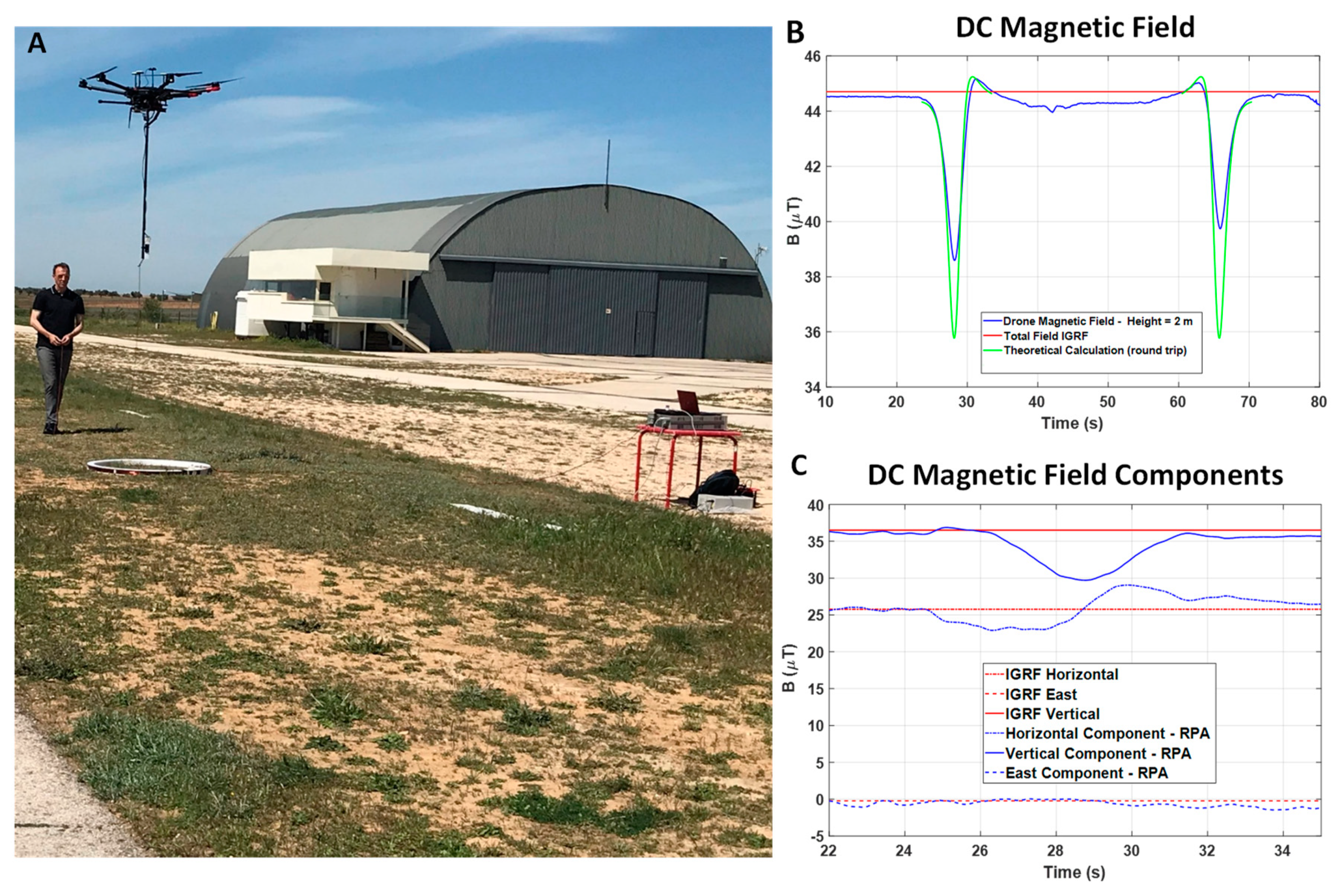
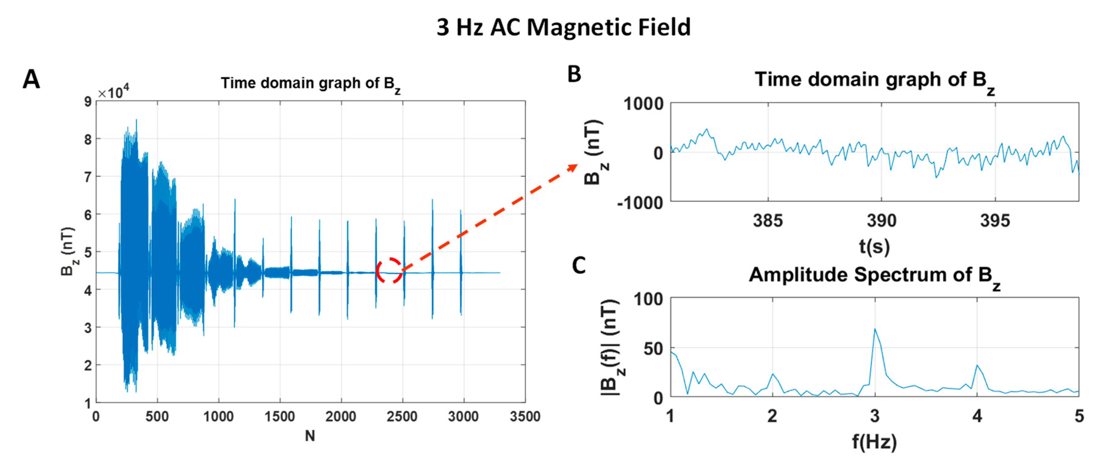
The DC and AC magnetic RPA signatures were measured at INTA Space Magnetism facilities in order to calculate the minimum distance that should be between the sensor and the drone for a given noise level;
Ad hoc design of the control electronics and acquisition of our payload, paying special attention to the materials used, the shielding of the cables and equipment and the filtering of the signal;
Development of the necessary software tools and flight procedures to fly as low as possible and at constant altitude in the area of interest, with the best orientation and low speed to achieve the best measurement of the magnetic anomaly;
Implementation of georeferenced data visualization tools with the capacity to perform post-processing with slight moving-average filtering.
There are different signal post-processing strategies in the literature [
10] that could be explored in future stages of this project by the INTA engineering team, but they have not yet been used in this phase of the project.
This work describes drone-based vector magnetometry at constant height as a potential methodology for the study, classification and interpretation of planetary structures with a precursor study of a spatter flow in Cerro Gordo crater of Campos de Calatrava Volcanic Province, Spain.
Section 2 describes the named MAGMA system, i.e., the implementation of a vector magnetometer (NOISE < 20 nT/√Hz) on a hexacopter, the mechanical configuration adopted for the system to assure a distance between the magnetometer and the RPA that is sufficient to diminish the magnetic contamination from the platform by means of a rigid boom, which permits the optimization of the navigation electronics, including the attitude instruments.
Section 3 details the calibration of the system.
Section 4 is focused on the experimental results of the field campaign and a preliminary interpretation of the results, and how they can be used in combination with models of the geological features under study for interpretations in the planetary context. Finally,
Section 5 briefly lists the conclusions.
2. System Design and Development
The MAGMA system, developed for magnetic surveys on Earth, is a precursor of the future platforms which will be used for planetary exploration. Therefore, the system is fully automated despite the fact that, on Earth, the pilot takes responsibility for the flights according to current legislations.
In this line, the system comprises a ground control station, a pilot and the platform with the payload.
The design of the system is directed to accomplish the scientific goals, i.e., to determine the vector signature of the magnetic anomalies associated with different geological features with a constant height flight, and to overcome technical questions such as the relative movement of the magnetic probe with respect to the platform, the variation in the magnetic signature of the platform on the magnetometer, depending on the relative position of the magnetometer and drone during the flight, the lack of accurate determination of the height in most low-cost drones, and, finally, that all the modifications to be done in the RPA respond to the maxim of achieving safe flights.
The sensor selected for the system is a three-axes fluxgate magnetometer, in contrast to other works, which use a scalar magnetometer. The instrument has approximately ±100 µT range and <6 pT/√Hz noise per axis. Its mass is 160 g and its volume is 32 × 32 × 152 mm. Based on this, the envelope of the payload is 2.054 kg, including the auxiliary electronics and systems. The selected platform, DJI Matrice 600 Pro [
11], is a relatively small platform with a load capability of 6 kg, with an expected autonomy of 16 min at full load. The MAGMA system has an autonomy of approximately 25 min. In contrast to the fixed-wing RPAs, it can cover very low altitudes and does not need a short runway for take-off and landing.
The targeted resolution is 1 nT per axis. To achieve this resolution, several questions need to be controlled, such as the temperature of the sensor, the acquisition system, the magnetic signature in the position of the sensor and the uncertainties in the orientation of the magnetometer.
Magnetic sensors are highly dependent on temperature. In the MAGMA system, the temperature of the sensor is monitored through a platinum resistor using the four-wire technique, which permits the magnetic measurement compensation. In our facilities at INTA, we can calibrate the magnetic sensors at different temperatures, obtaining the transfer functions of gain and offset per axis. These calibration files are used in the post-processing of the data. The acquisition module conditions the magnetometer and thermometer signals and transmits them to the ground control station. It is based on a delta-sigma ADC of 24 bits. Before digitalizing, the system includes a 4 Hz anti-aliasing filter.
The magnetic signature of the drone has been characterized in DC and in frequency, paying special attention to the frequencies of the motors and their subharmonics. The magnetic moment of the RPA with the motors off is 83 mA·m2. Depending on the rotation speed, the total magnetic moment varies between 108 and 156 mA·m2. The main frequency contributions are between 30 and 107 Hz, and will be filtered by the acquisition module. Both contributions of the magnetic signature (DC and in frequency) have been considered when calculating the distance from the boom at which the magnetic sensor must be located. Therefore, in order to guarantee an attenuation of the stray magnetic field lower than 10 nT, the magnetometer needs to be placed at least at 1.2 m distance from the main structure and the electronic parts. On the other hand, vector magnetic measurements require knowledge of the spatial position and orientation of the sensor on the X, Y and Z axes. This is not compatible with the typical configuration of a magnetometer towed by the drone with a cable. In contrast, a system with a rigid and articulated boom has been adopted in the design. In this way, the attitude and orientation control and determination system of the platform can be used to determine that of the magnetometer.
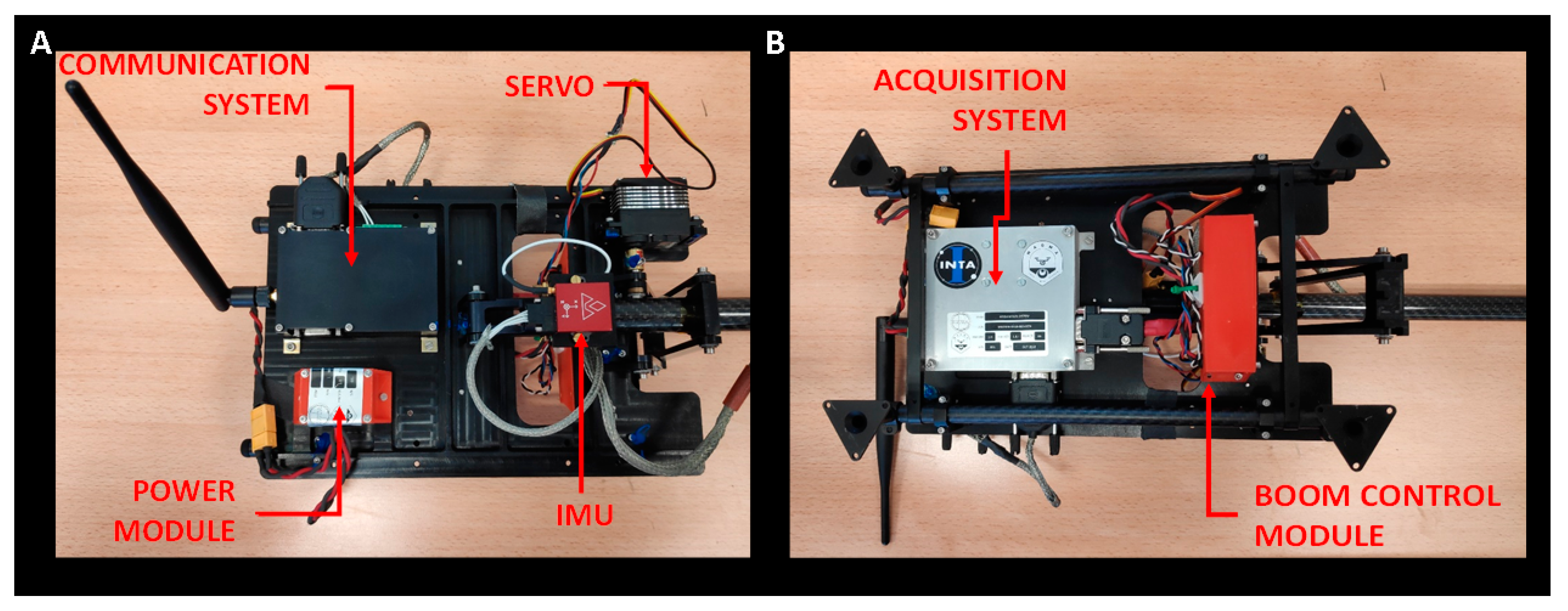
These data form part of the drone avionics and could be retrieved. However, with the aim of having a modular architecture for more versatility and interchangeability in different drones, MAGMA system has been provided with an ad hoc inertial measurement unit (IMU) and Ground Positioning System (GPS) solidary with the payload (
Figure 1). Traditional navigation or tactical grade IMUs are heavy and expensive, and therefore not suitable for most professional drones with limited pay-load weight. The IMU employed in MAGMA system is a high-performance, GPS-Aided inertial navigation system very small and light. Using an advance GPS module with Micro-Electro-Mechanical System (MEMS) inertial and pressure sensor technology provides a dynamic accuracy better than 0.3° in heading, 0.1° in pitch/roll. This type of IMU has been used for different applications with drones with good results [
12,
13].
The power system for the payload and the auxiliary electronics have been allocated in an interface plate attached to the body of the drone. All the structural and mechanical parts of the interface plate are made in low-magnetic-permeability materials (bronze for the pins, titanium for the screws and black anodized aerospace aluminium alloy 7075T6 for the interface plate). Additionally, the signal and power cables have been shielded and braided to minimize magnetic noise and electromagnetic interference. The complete system has been designed as a payload that is totally independent of the aerial platform that transports it. The system can be powered by batteries or, if the RPA allows it, can be powered by the drone’s batteries. In this case, to reduce weight, the system uses the drone’s batteries.
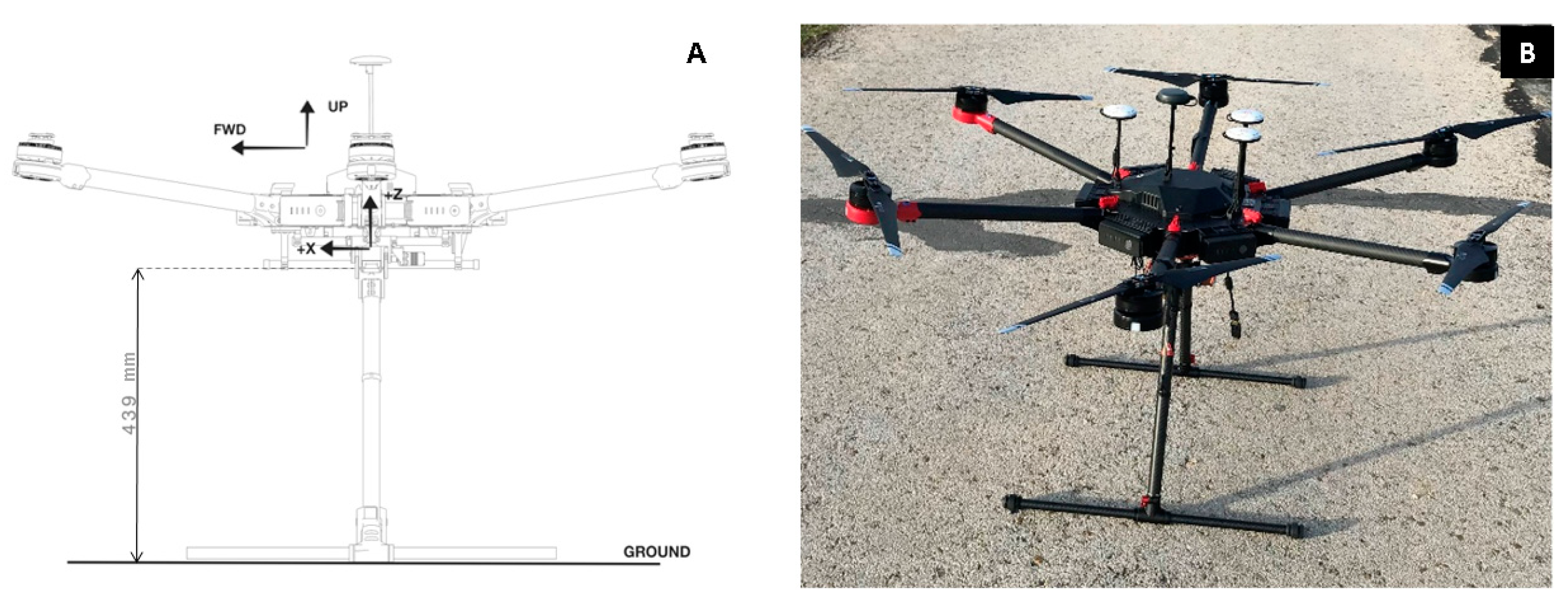
The design of the boom and its control and operation constitute one of the most challenging parts of the system.
The final design had to find a trade-off between the length required by the magnetic contamination in the position of the sensor, 1.2 m, and the RPA clearance (in the order of 0.4 m) when landed (
Figure 2), and be compatible with the RPA capabilities, in particular, with its maximum take-off weight of 15.5 kg.
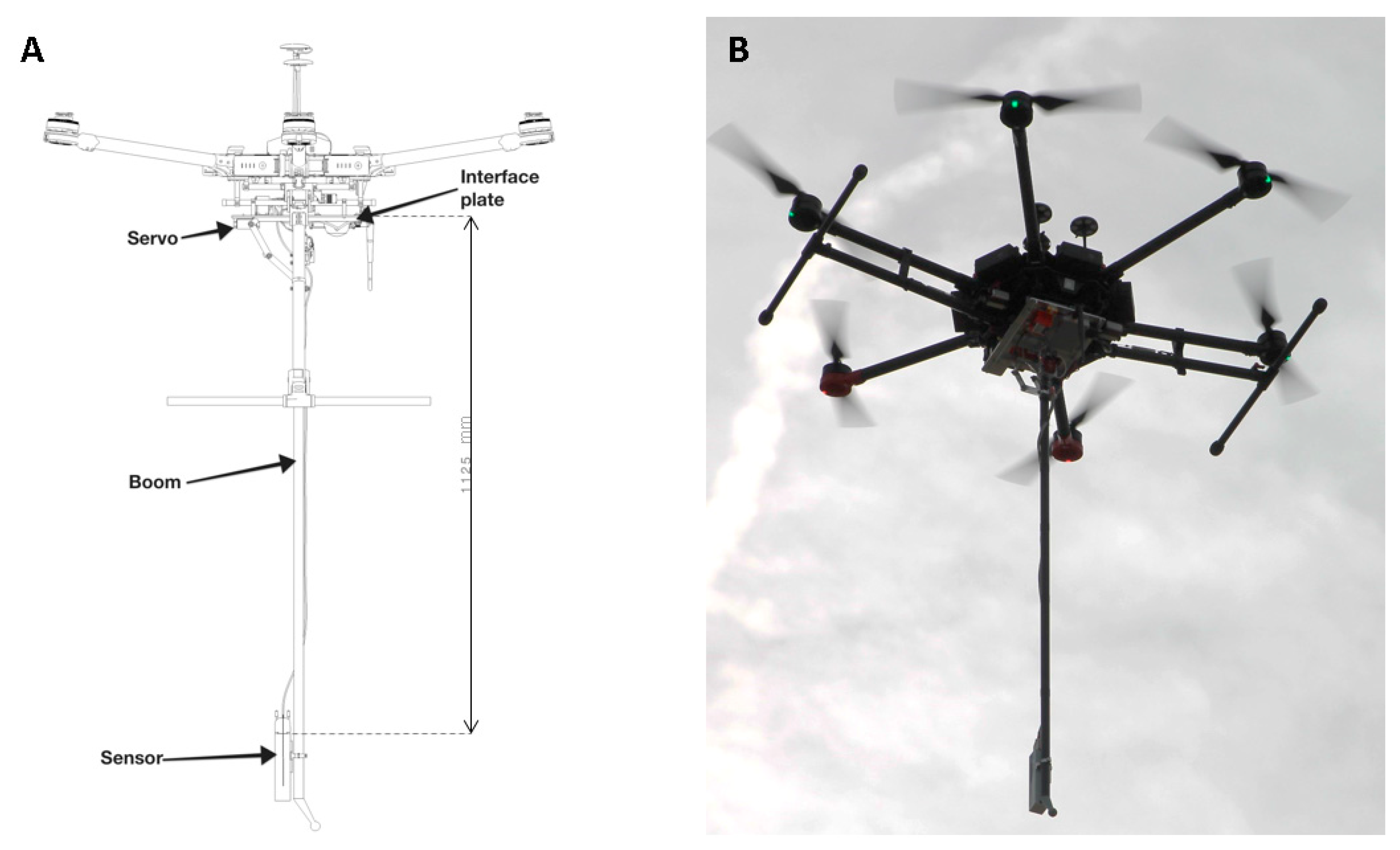
The mechanical design consists of a rigid boom with the magnetometer at its farthermost end (length 1.2 m) connected to a stiffened interface plate that is attached to the RPA expansion kit (composite frame provided to attach custom payloads) at four points using clamp type fittings. The solution, similar to the drone landing gear, allows for proper distance during measurement, together with accurate position, by using a rigid carbon composite tube as boom (
Figure 3).
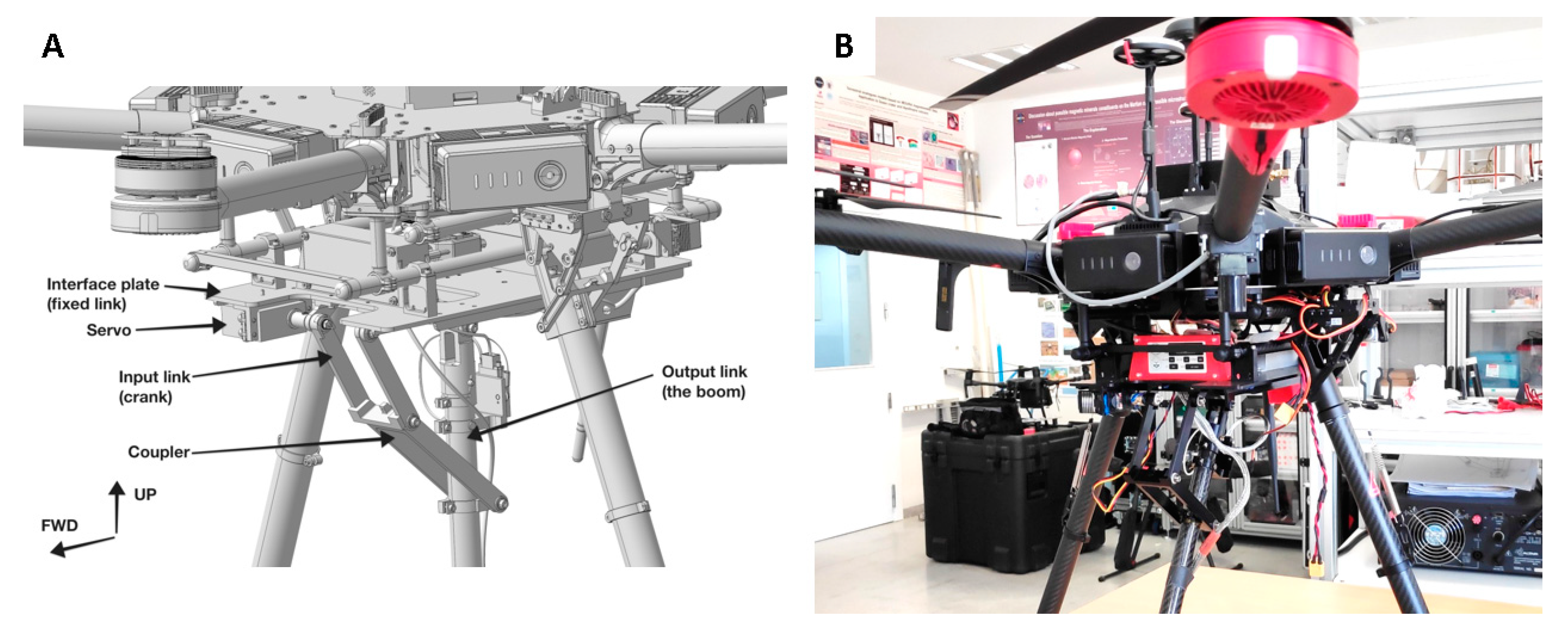
The boom is foldable to a horizontal position for taking off, and landing by means of a standard size servo with a stall torque in excess of 4 N-m was required. Dynamic behaviour for peak torque analysis (retraction and deployment) was done later, during the development phase, to verify sizing using the Adams software package [
14]. The retraction and extension capability with the servo is implemented via a four-bar mechanism (
Figure 4) in order to define the appropriate kinematic behaviour and mechanical advantage required to optimize torque requirements. In the folded position, the servo-holding torque keeps the boom retracted, and in the deployed position, the holding torque keeps the boom pointing downwards to the required accuracy.
The whole system has a take-off mass of 11.5 kg, giving sufficient scope for operations.
At every moment, the pilot from the ground station manages and can take the control of all the flight manoeuvres.
The communications are based on a commercial radio link with a standard RS232 interface between the drone and the ground control station, which provides a virtual link between the acquisition system and the ground control computer. The deployment system of the boom is directly commanded by the drone remote controller, with an operation independent of the acquisition part and standard Remote Controller Pulse Width Modulation (RC PWM) signal between 900 and 2100 µs, and coordinated with the drone flight operations.
To ensure the quality of the scientific data, a quick-view tool has been included in order to optimize the field work.
Even though the magnetic signature of the drone is minimized in the position of the sensor, the planification of the routes will use one-direction tracks, in particular, North–South transects. In order to achieve highest accuracy in the orientation of the tracks, Keyhole Markup Language (KML) file or other types of files with GPS information (latitude and longitude) are used for the track planner.
We have developed a series of software tools in MATLAB® in order to create the needed waypoints perfectly oriented to carry out magnetic surveys of any interested scientific place. The user can select different route parameters, such as number of survey lines or separation distance between them, in order to accommodate the number of waypoints of the route KML file. The application also permits the management of digital elevation models (DEM) with accurate terrain elevation data in order to incorporate the desired altitude to the final route file. At this point, other important aspects are the selection of the DEM and the tools used to guarantee the flight height. There are many sources of precise DEM data. Some of them are available under demand to country authorities, and others are expensive commercial products. High-resolution magnetic measurements need highly accurate DEM in order to guarantee a safe height over terrain with an appropriate tolerance.
In addition, most drones use barometric altimeters to calculate their altitude relative to the take-off position. These barometric altimeters have some drift depending on the quality of the sensor, the air temperature changes and other climate factors. On a 30 min flight, the maximum drift can reach up to 5 m, which has implications for the safe height over terrain.
In the surveys of terrestrial analogous for planetary explorations, often located in distant and rural or non-populated areas, it is common not to have an accurate DEM.
For this purpose, the navigation is not based on the barometric sensor, but uses the reference of an altimeter laser to correct the height of the drone’s flight, which is continuously set by the pilot. The system provides both flight modes (DEM and terrain-following). In our experience, to obtain the most accurate magnetic anomaly results, it is best to use the terrain-following mode. However, it must be noted that this is a riskier technique.
4. Results: System Demonstration in a Volcano and Example of Application for Planetary Exploration
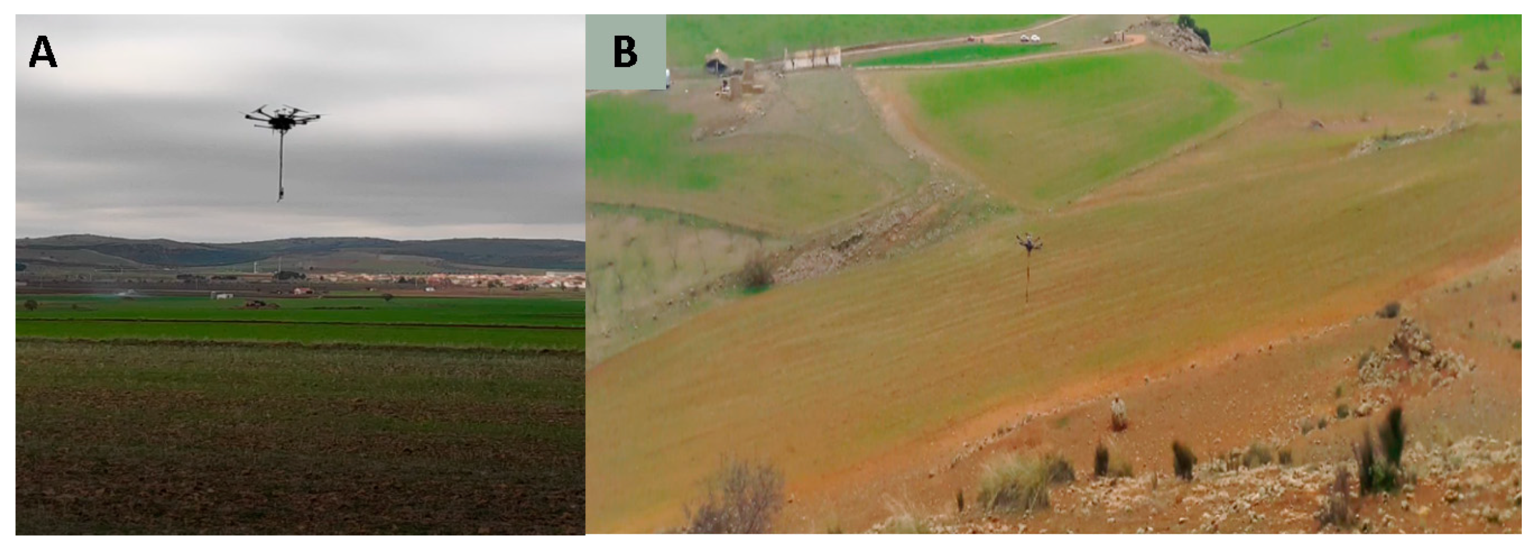
The system was demonstrated in Cerro Gordo Volcano (38°49′54.8′′N, 3°44′31.43′′W) in Spain. Cerro Gordo is situated at the Eastern part of Campo de Calatrava (Ciudad Real, Spain) constituting the Calatrava massif, the intensively eroded Almagro-Bolaños, anticline, and the Moral-Calzada de Calatrava basin.
The past volcanic eruptions, either effusive or explosive, in the East of Campo de Calatrava, are associated with a fault in the NE-SW direction.
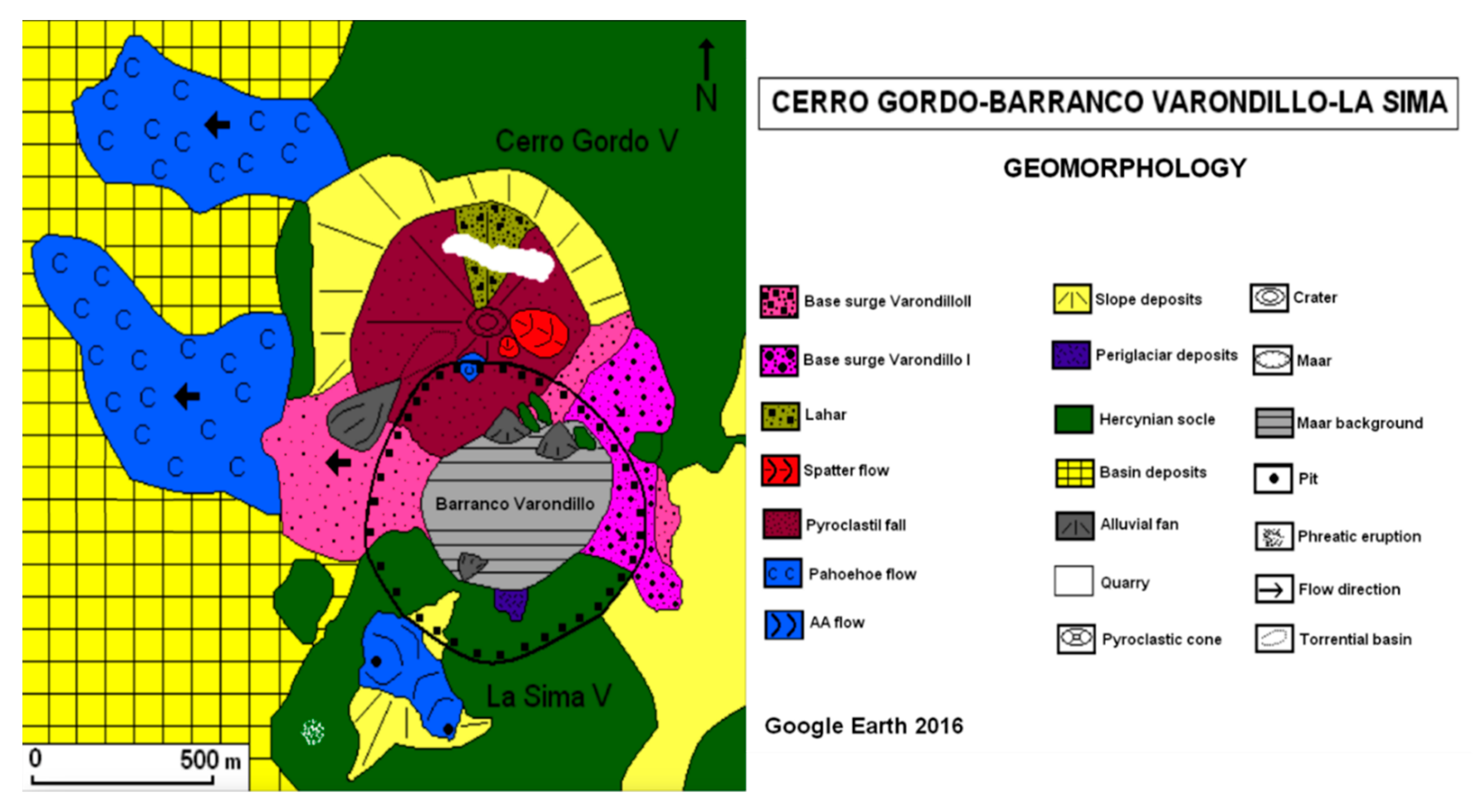
Here, the volcanic lineament of the Sierra de Valenzuela gathers five volcanoes formed by explosive eruptions of Strombolian and phreomagmatic types. The Cerro Gordo volcano is characterized by explosive eruptions, and to a minor extent, effusive eruptions producing lava flows (
Figure 7).
Currently, the area is intensively used for agricultural purposes. Even though the rocks have been partially moved, the colour of the terrain roughly shows the location of the lava flows.
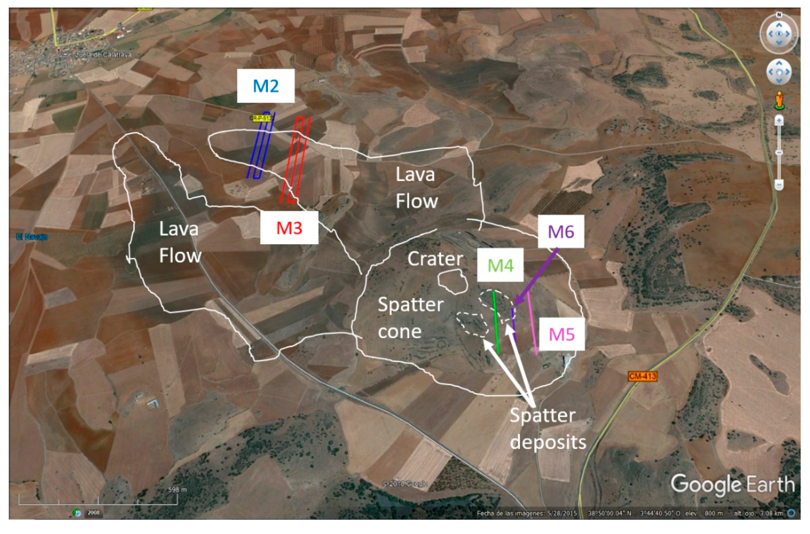
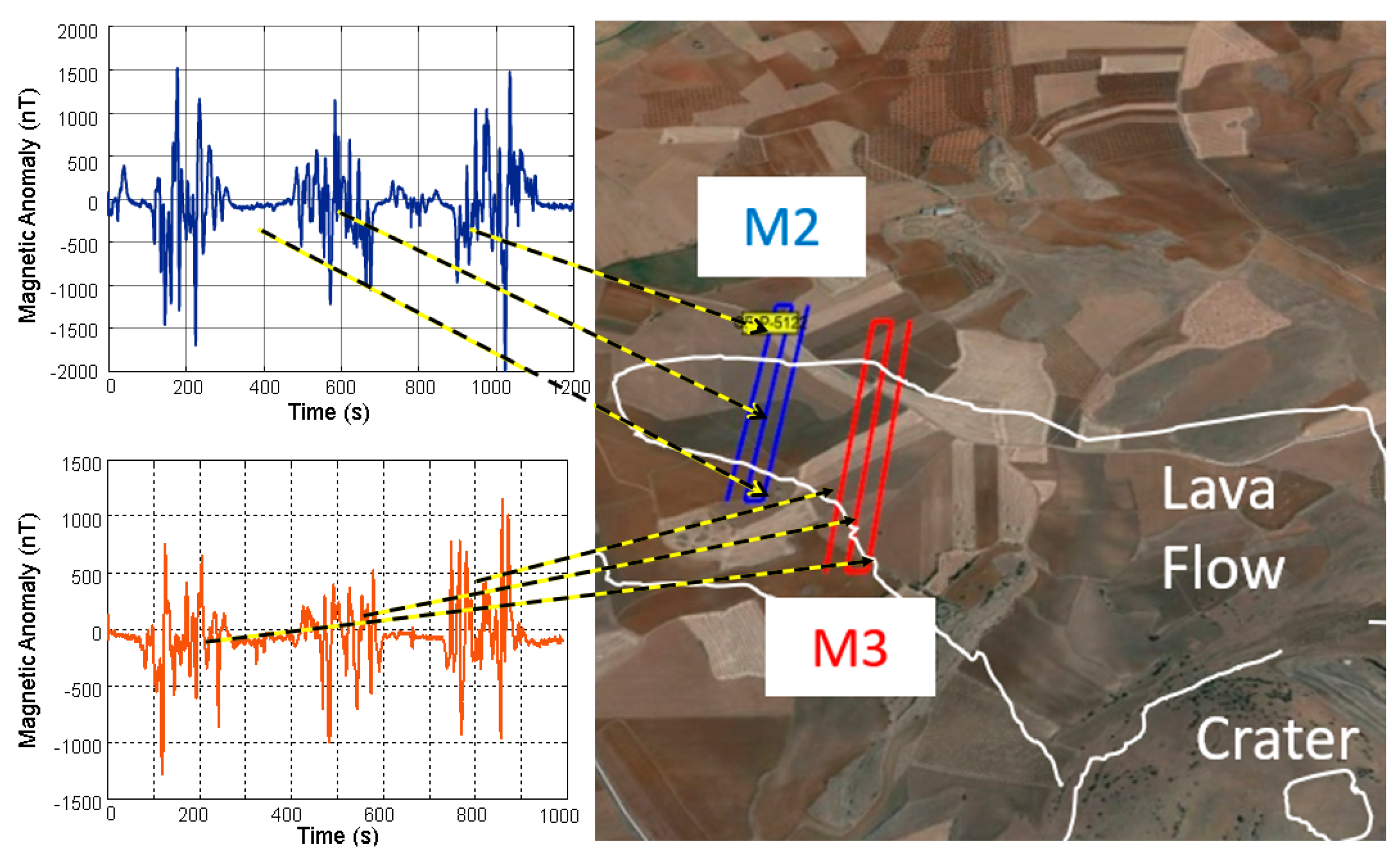
The missions were planned to characterize the contrast produced by lava flows and the spatter deposits (
Figure 8). It has to be taken into account that the area where the lava flows lies is relatively flat. However, the slope of the volcano with spatter deposits presents a height difference in the order of 70 m. However, the slope of the volcano with spatter deposits presents a height difference in the order of 70 m (
Figure 9).
As described in
Section 2, to mimic on-ground measurements, the flight navigation followed the topography in a 5 m flight over the surface, maintaining the magnetometer at 3.8 m over the terrain. The drone speed was 1.5 m/s. A visual control is needed when there are trees or other obstacles that could hinder an unproblematic flight course.
Figure 10 shows an important contribution of the lava flows to the magnetic signature, with variations up to 1500 nT. The high variability is also associated with the movement of the land for agriculture.
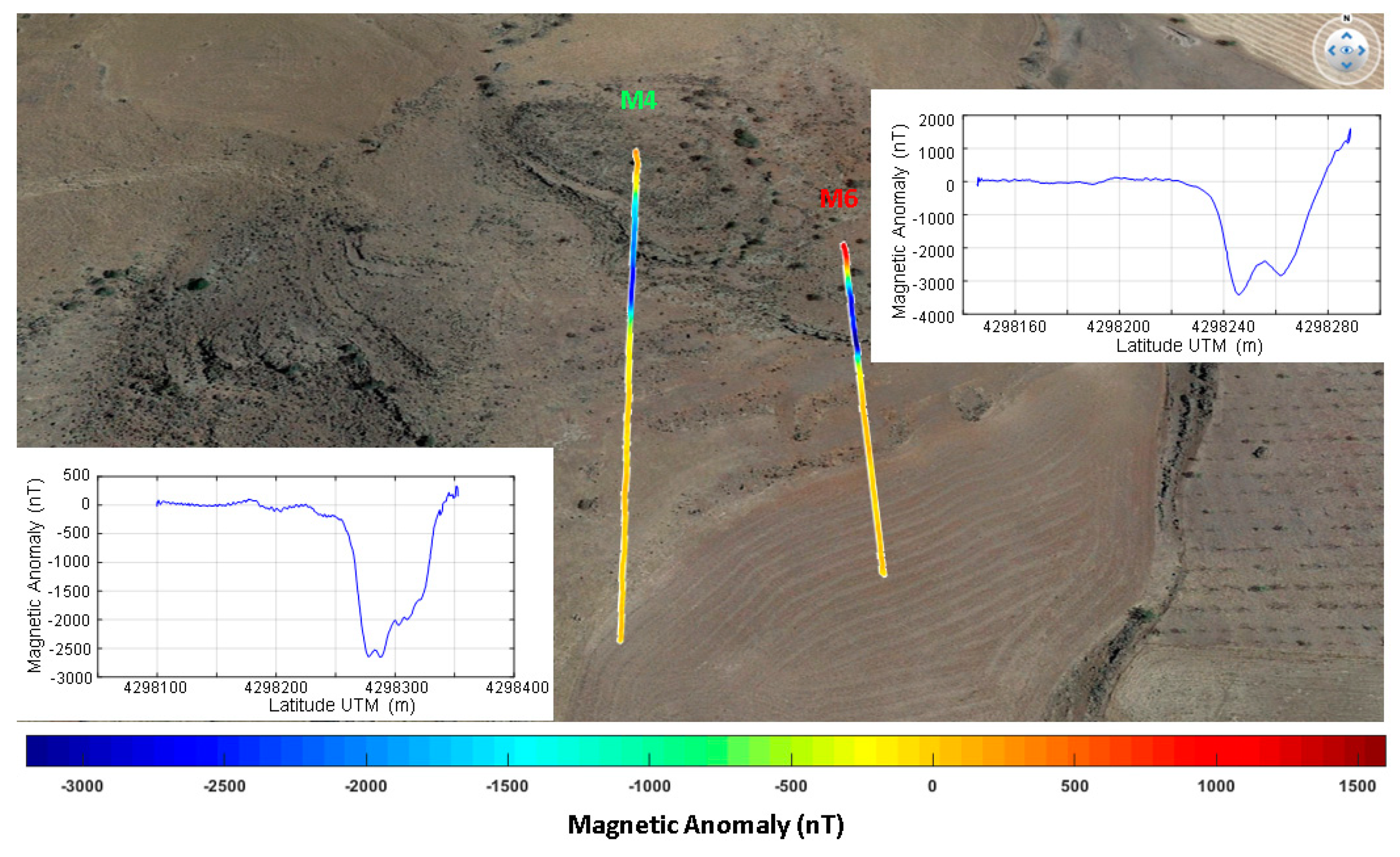
Figure 11 shows the field intensity recorded as a result of an overflight over the spatter deposits. The magnetic signature of the spatter deposits presents negative anomaly values around −3500 nT.
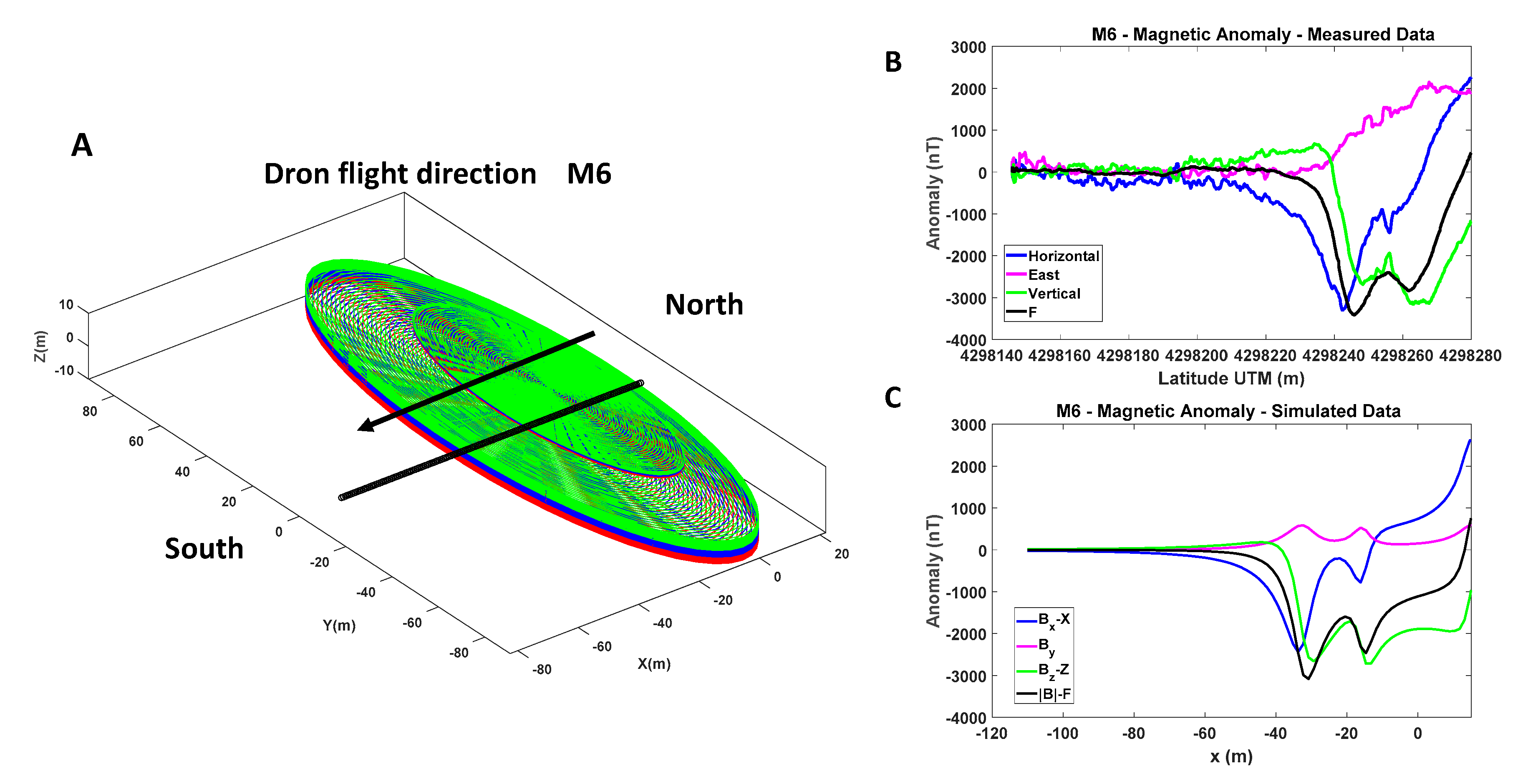
The result is not compatible with a body with induced magnetization by the present geomagnetic field, but has a declination that is compatible with the magnetization acquired during a geomagnetic reversal. Several samples were collected in the exposed wall of the deposit. The samples were characterized in the laboratory. Based on the magnetic susceptibility of the samples, the body was modelled as two three-layer cylinders with magnetization according to the susceptibility values and with south declination; see
Figure 12a.
The anomaly produced by this model reproduces the anomaly measured during the flight (M6) in the Southernmost end fairly well; see
Figure 12b,c. The discrepancies are attributed to the differences in shape, in particular in the thickness of the upper part (north) of the spatter deposit, which is a more complex structure whose composition is not exactly known.
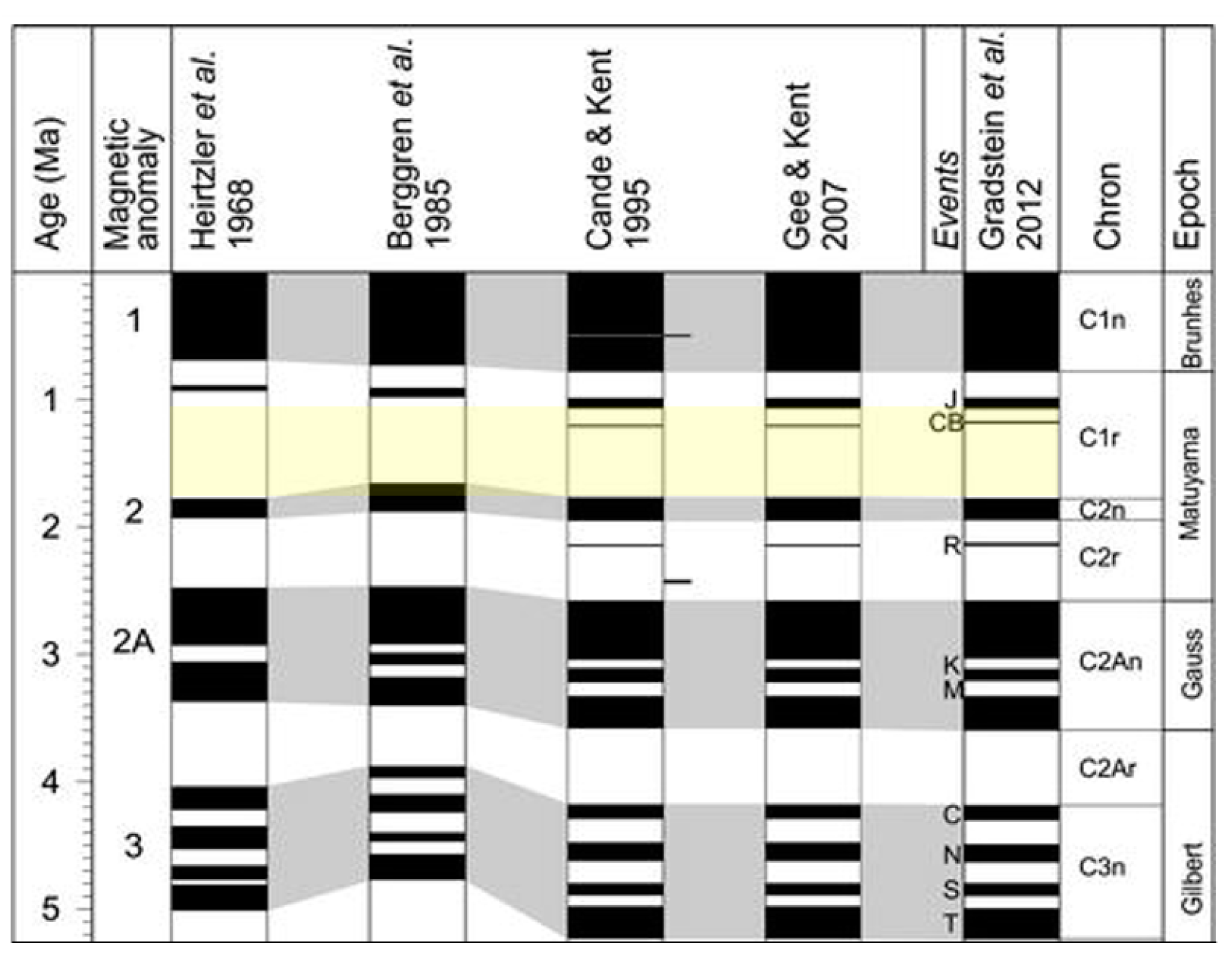
This scenario seems to point to an eruption during a period of time with inverted geomagnetic declination. Since the date in which this late eruption took place has been reported to be in the end of the Pliocene (5–1.8 Ma) and the beginning of the Pleistocene (1.8 Ma–11,000 years), Matuyama reversal chron seems to be the most appropriate candidate (
Figure 13). A more profound investigation should be carried out to better constrain this aspect.


 ,
, 


