Abstract
Synthetic aperture radar systems operating with satellites in geosynchronous orbits (GEO-SAR) can provide a permanent coverage of wide specific areas of the Earth’s surface. As well as for primary applications in remote sensing areas such as soil moisture and deformation monitoring, the wide availability of the signal emitted by a GEO-SAR on a regional scale makes it an appealing illuminator of opportunity for bistatic radars. Different types of receiving-only devices located on or near the Earth could exploit the same signal source, noticeably already conceived for radar purposes, for applications in the framework of both military and civil surveillance. This paper provides an overview of possible parasitic applications enabled by a GEO-SAR illuminator in different operative scenarios, including aerial, ground and maritime surveillance. For each selected scenario, different receiver configurations are proposed, providing an assessment of the achievable performance with discussions about the expected potentialities and challenges. This research aims at serving as a roadmap for designing parasitic systems relying on GEO-SAR signals, and also aims at extending the net of potential users interested in investing in GEO-SAR missions.
1. Introduction
Synthetic aperture radar (SAR) imaging represents today one of the most powerful tools for active Earth Observation from space. Usually, spaceborne SAR instruments operate with satellites in low Earth orbit (LEO), with a revisit time in the order of several days (depending on the orbit inclination and the latitude of the observed area), representing a major limitation of such sensors. In contrast to LEO-SAR systems, geosynchronous SAR (GEO-SAR) configurations could provide a permanent illumination of wide areas of the planet. Originally proposed in 1978 by Tomiyasu [1], the GEO-SAR concept has been studied for many years, exploring several aspects of the mission design, such as the coverage, orbit, atmospheric perturbation and impact of Radio Frequency Interference (RFI) [2,3,4,5,6,7,8,9].
Over the last few years, researchers have assessed a wide range of primary remote sensing applications for GEO-SAR missions, including earthquakes, soil moisture, snow mass monitoring and meteorology [2,10,11], arousing the interest of scientists and policymakers attracted by the unprecedented potentialities in terms of frequent revisit time. The growing interests of several users and stakeholders is accelerating the transfer process from the concept and feasibility studies toward the operative phases.
Thus far, a few studies have considered surveillance applications, mainly focusing on the possibility to detect moving targets by means of ground moving target indication (GMTI) approaches [12]. Nevertheless, such a type of approach seems barely appealing for safety and security services, due to the very long integration times required to cope with very high satellite altitude. To extend the range of potentialities to surveillance applications, in this work we propose secondary utilizations of the signals transmitted by the GEO-SAR system. The idea is to resort to bistatic radar configurations comprising receiving-only devices on or near the Earth’s surface that parasitically exploit the signals emitted by the satellite. A similar concept has been proposed in [13], assuming a high-power cooperative geosynchronous illuminator and LEO satellites/unmanned airborne vehicles as receivers for ground and aerial moving target indication. Conversely, in this work we assume a non-cooperative illuminator, whose design has been tailored for primary remote sensing applications, and we consider different classes of receivers depending on the specific surveillance task to be addressed. Such a type of radar configuration is known as passive radar.
Passive radar, also known as parasitic radar [14], is a class of radar systems in which the sensors are not equipped with a dedicated transmitting segment, but they capitalize on the signals already existing in the environment (signals of opportunity) [15]. This lowers the cost of the system and its maintenance, allowing for sensors with reduced size, weight and complexity. These factors, together with the low power consumption and the reduced environmental impact, facilitate the installation and multiple deployment of such systems, even in places where active radars cannot be installed or are undesired due to their harmful radiations. While the traditional choice for passive radar configurations is exploiting terrestrial illuminators (e.g., DVB-T signals), over the last few years new ideas about passive radar applications relying on satellite transmitters have begun to emerge. A suitable solution is represented by Global Navigation Satellite Signal (GNSS) constellations: for many years their opportunistic exploitation has been well known by the remote sensing community for reflectometry [16] and passive SAR [17] applications, and, more recently, their alternative utilizations for passive coherent locations have also been explored [18,19,20]. Other noteworthy options are represented by communication satellites such as Iridium and Inmarsat [21], and broadcast systems such as DVB-S transponders [22,23,24].
The parasitic exploitation of GEO-SAR signals could be an appealing solution for several applications where employing a light, green and easily deployable receiver is highly desirable.
First, such a system can rely on transmissions from space, assuring a coverage even in those environments where terrestrial signals are absent (e.g., in open sea) or their reception is hampered by the particular terrain conformation (e.g., mountain areas). In addition, the system is less susceptible to multipath effects and its operability is not easily compromised by manmade or natural disasters.
As the systems leverage on a SAR instrument, it can benefit from a waveform already conceived for radar purposes, and, therefore, has better properties of the ambiguity function than commercial illuminators using non-native radar waveforms. It should also be noted that for a few commercial satellites such as mobile communication systems (e.g., Iridium), the availability of the signal might even be subject to user demand and, therefore, not persistent. A further fundamental benefit offered by SAR signals is the availability of bandwidths much wider than most communication satellites, often using narrowband signals (e.g., a single frequency channel of Inmarsat I-4 has a nominal bandwidth of just 200 kHz) that limit the effectiveness of the system, especially in multi-target scenarios. The wide bandwidths adopted by current SAR missions (from tens up to a few hundreds of MHz), enable range resolutions comparable or even better than the size of several targets of interest, such as aircraft, ships or ground vehicles, also sensibly reducing system sensitivity to clutter echoes.
Finally, the selection of an instrument mounted on a GEO in lieu of an LEO satellite can guarantee a continuous signal availability over a large area. LEO platforms are in visibility of a geographic area for a limited amount of time, and a constellation of satellites would be needed to assure continuity of the coverage, with the further issue represented by the handover. Furthermore, passive systems typically use a dedicated receiving channel to record the direct signal as reference to enable the radar operations: in the case of LEO illumination, such a direct channel should possess tracking capability to properly follow the fast trajectory of the satellite. In contrast, a GEO illuminator keeps a nearly static position in the sky allowing an easier recording of its direct signal, which can be captured by using narrow-beam and high-gain antennas, assuring also robustness to interferences from other RF sources.
Prompted by these good characteristics, in this work we investigate which types of applications can fruitfully be enabled by GEO-SAR signals. In particular, we refer to satellites operating on geosynchronous orbits with small eccentricity, which are gaining momentum due to their capability to provide a near-continuous imaging with relaxed requirements for the system design [9]. We introduce parasitic concepts based on the availability of the emitted signals on a wide area referring to three main scenarios: aerial, ground and maritime surveillance. For each scenario under consideration, a few specific applications have been detailed. In each case, a feasibility study has been carried out to assess the achievable performance, discussing the expected potentialities and challenges to meet the main user requirements of the particular surveillance application. The purpose of the research is to provide a roadmap for designing parasitic systems exploiting GEO-SAR signals, with the ultimate goal to increase the number of applications that might justify investments in the forthcoming missions.
The paper is organized as follows. Section 2 describes the GEO-SAR system considered in this study. Aerial, ground and maritime surveillance applications are addressed in Section 3, Section 4 and Section 5, respectively. Section 6 provides a summary of the research findings and draws the conclusions.
2. GEO-SAR Parameters
The GEO-SAR system considered in this study belongs to the quasi-geostationary class, characterized by a nearly zero inclined eccentric orbit; such orbit configuration has been found attractive for GEO-SAR missions, as it could allow remarkable imaging performance with relaxed requirements for antenna size and power demand. While high inclination orbits would require very large antenna diameters (20–50 m) and several kW of transmitted power, low inclinations allow much lighter antennas (2–6 m diameter) and few kW or even less [6]. These factors could facilitate mission design using current technologies in terms of power and antenna reflectors [3,9], and, therefore, are the most promising to become operative.
Table 1 lists the parameters here assumed for the GEO-SAR. In particular, we focus on an X-band instrument transmitting wideband pulsed waveforms and operating with an antenna diameter of 5 m, resulting in an area of about 20 m2. Moreover, the considered peak power and duty cycle bring a mean transmitted power = 400 W. These parameters are compliant with related studies on low-inclination geosynchronous SAR missions [9].

Table 1.
Parameters of the GEO-SAR system.
As aforementioned, the main highlight of such a configuration is that it maintains near-continuous coverage of a regional area. Taking into account the operative frequency and the orbital choice, we assume a footprint in the order of 300 km × 300 km (evaluated at the −3 dB level from the beam centre) [9,11]. Figure 1 shows an example of coverage using four simultaneous beams steered toward the Italian territory. A higher number of beams could be assumed to further extend the coverage; however, in such a case, we assume that additional feeds are mounted on the payload, therefore not affecting the following power budget analysis.
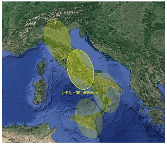
Figure 1.
Example of GEO-SAR signal coverage of the Italian territory using four beams.
The average power density available at ground level for each beam can be evaluated as
where is the transmitting antenna gain, being its effective area, which includes the aperture efficiency . includes the signal power losses due to atmospheric propagation. is the satellite distance from the Earth’s surface, approximately given by
being the Earth’s radius. Considering the parameters in Table 1, such a distance is approximately equal to 37,667 km. Assuming is equal to 4 dB to account for the potential transmission and propagation losses, an average power density in the order of (−95,−98) dBW/m2 is expected within the main lobe footprint area of each transmit beam (see Figure 1).
As it is apparent, the price to be paid for the good properties of the opportunistic illuminator under consideration is the restricted power budget provided, representing the main obstacle to be addressed to enable surveillance tasks. Therefore, the key element to be analysed in order to assess the feasibility of the secondary applications is the link budget. Let us consider a generic target characterized by radar cross section (RCS) within the footprint of one beam and located at distance from the receiver using an antenna with gain . The signal-to-noise ratio (SNR) achievable after waveform compression and coherent integration of multiple pulses over a coherent processing interval (CPI) of length is given by
where is the wavelength, is the Boltzmann constant, is the standard noise temperature and is the receiver noise figure.
While the transmitter parameters are defined according to the mainstream remote sensing applications and therefore are not under the control of the parasitic system, higher degrees of freedom can be exploited for the receiving system design. In the remainder of the work, we will propose several solutions for each identified secondary application, taking into account the available SNR and the main user requirements. In the analysis, the possible presence of clutter will be neglected. Indeed, the most critical factor affecting the concepts feasibility and the design of the receiving systems is the low power density made available by a non-cooperative geosynchronous satellite, while appropriate signal processing techniques could be adopted to eliminate possible clutter deleterious effects.
Table 2 summarizes the parameters used to compute the SNR taking into account the assumed GEO-SAR parameters reported in Table 1. It is worth pointing out that denotes a bistatic RCS. As is well known, the bistatic RCS could differ from its monostatic counterpart, and its characterization is a difficult task, especially in the case of complex objects of very different classes such as aerial, ground and ship targets. This topic is well beyond the scope of this work and, therefore, for the feasibility study of parasitic surveillance potentialities here addressed, in the remainder of the work, the typical values available in the literature for monostatic RCS in X-band will be considered.
Table 2.
Radar equation parameters.
3. Aerial Surveillance
The availability of a persistent illumination over large areas enables potential air traffic surveillance applications, relying on the use of ground-based passive receivers in bistatic configuration. The echoes from cooperative and non-cooperative aircrafts may be collected, parasitically exploiting the satellite power density available up to 10–12 km from the Earth’s surface. In this section, we illustrate the concept of a GEO-SAR-based passive radar for air traffic surveillance and propose potential user requirements for different application scenarios. Then, a performance analysis is carried out to evaluate the feasibility of such a concept and investigate the possibility of it complying with the requirements set.
To this purpose, based on the idea that the proposed bistatic sensors might complement (or possibly enhance) the performance of existing technologies in specific scenarios, we refer to the standards and recommendations regulating the international civil aviation.
3.1. Conventional Radar Systems for ATC
Air Traffic Control (ATC) services regulate air traffic, prevent collisions between aircraft, and between aircraft and ground obstructions. These tasks are accomplished by means of several surveillance systems, whose use and requirements are regulated by the International Civil Aviation Organization (ICAO). Surveillance systems provide the controller and ground-based automation with the required information. For this purpose, a combination of cooperative and non-cooperative systems is usually employed [25,26,27,28,29,30,31].
Radar systems play a crucial role in many operational scenarios, thanks to the capability to detect any aircraft within their coverage area without requiring cooperation by the targeted aircraft. Among the primary radar systems,
- Airport Surveillance Radar (ASR) is an approach control radar used to detect and track aircrafts in the terminal area. It usually operates in S-Band and provides reliable detection of aircraft at altitudes below 25,000 feet and within 60 nautical miles from the airport, with 360° azimuth coverage and update times below 5 s.
Additional specialized radars are employed in other divisions of control. Common applications include:
- Precision Approach Radar (PAR), which provides ground-controlled guidance information for aircraft landing;
- Surface Movement Radar (SMR), which locates aircraft and ground vehicles’ positions within a few kilometres on the airport surface;
- Collision Avoidance (CA) radar, which operates to prevent unintentional contact with other aircrafts, obstacles or the ground.
The specifications provided by the authorities for the abovementioned ATC radar systems can be found in [25,28,29,30,31]. When these are not explicitly defined, the typical performance of commercial systems have been considered in the following.
Most of the considered radar systems use large rotating antennas and associated machinery. They typically require several pieces of equipment, cooling systems, backup generators and a consistent energy supply. Moreover, their installation typically takes several months for site preparation and deployment. Besides the costs, a wide range of drivers may contribute to the way in which surveillance infrastructure would need to operate in the future [26], including increasing traffic density, new types of aircraft and construction techniques with reduced radar cross sections, increasing use of secondary airports and the introduction of spectrum charging schemes and RF congestion.
Spectrum pressure and cost drivers might possibly carry to less use of conventional primary radar surveillance systems in favour of cooperative systems, based on targets equipped with transponders, which nowadays represent a principal component of ATC. Nevertheless, non-cooperative surveillance will continue to be required for reasons of safety and security and to guarantee the full situational awareness against intrusions by non-cooperative aircraft or aircraft experiencing failures.
In this regard, multi-static primary surveillance radar (MSPSR) represents a viable solution. This technology, currently under development, is expected to provide several advantages by exploiting multiple transmitters and receivers in a multi-static mode to detect and localize aircrafts. Surveillance at a lower altitude (<10,000 ft) could be achieved by exploiting transmitters of opportunity, ensuring spectral efficiency and reducing costs. The fusion of different techniques is expected to be one of the most important trends of the next years with the aim to obtain the best cost benefit depending on local constraints. These key elements motivate our investigation for a GEO-SAR-based passive solution.
3.2. Passive Radar Concept for Air Surveillance
The use of passive radar for air traffic surveillance applications has received considerable attention in the last few decades. Ground-based receivers exploiting the illumination offered by transmitters of opportunity can be employed as a gap-fill/back-up technology on specific airspaces and in particular scenarios (e.g., low altitude surveillance) [32,33]. Moreover, the idea of applying passive radar on board aircraft has been investigated, to protect the platform from collisions and other threats [34,35]. Most studies have considered the use of ground-based emitters, such as radio/TV broadcasting, [36,37]. However, the main limitation of VHF/UHF emitters is the poor achievable accuracy in terms of target localization and motion parameter’s estimation due to the low available carrier frequency and bandwidth, being unsuitable for use against dense traffic in the area surrounding airports. Moreover, the radiative characteristics of typical ground-based transmitters [38] and the emitted waveform can significantly affect the achievable performance.
The parasitic exploitation of satellite transmitters may represent a viable solution to several of the issues above. Only a few contributions have considered satellite emitters of opportunity for aerial surveillance applications. In [39], the authors exploit the 2.3 GHz downlink of the geostationary XM-Radio satellites to detect aircrafts at short distance. Noticeably, the proposed passive radar system exploiting an X-band GEO-SAR as an illuminator of opportunity represents an innovative solution for air traffic surveillance. In fact, it is expected to complement the existing solutions and enhance the performance, at least in selected scenarios, widening the network of potential receivers for pervasive aerial surveillance.
The concept of the proposed system is illustrated in Figure 2. By deploying one or more ground-based receivers that collect the echoes from potential aircrafts and vehicles, several functions can be developed, as those foreseen for the conventional ATC surveillance radar, with the well-known advantages of non-emitting systems.
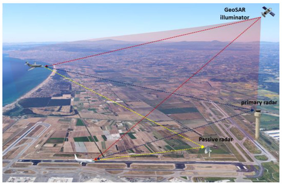
Figure 2.
Concept of GEO-SAR-based passive bistatic radar for air surveillance.
Depending on specific applications, the proposed passive sensor might be employed as a stand-alone technology to replace the conventional systems, or to restore a basic performance level when the existing radar is disabled due to unwanted events. Moreover, it might be thought as an auxiliary technology, to monitor specific areas where the coverage of the existing sensors is not guaranteed or to extend their capabilities.
In this study, potential system requirements are provided for the case of the application of the passive sensor as an auxiliary technology within a more complex system jointly exploiting mixed solutions, as, for example, in MSPSR. This allows us to define a set of possible specifications for different ATC application scenarios by relaxing some of the requirements compared to those generally provided for the conventional radar systems.
The set of selected requirements for each considered application is summarized in Table 3. Specifically, it is expected that a GEO-SAR-based passive radar could be employed as an auxiliary solution for ASR and SMR systems. The range and angular coverage requirements have been reduced, compared to those of the conventional sensors, assuming to deploy a network of receivers and/or to cover a limited area or sector where the coverage of the existing sensors is not easily guaranteed. Similarly, the potential exploitation as a PAR system is also considered. Furthermore, we report the possible requirements for use in airborne applications as a low-cost CA system. This would enable civil airliners and general aviation aircraft to be equipped with a stand-alone solution for collision avoidance applications as commonly adopted for military aircrafts. Finally, we report the tentative requirements for a possible application to the detection of commercial drones. While this application is of high interest and actuality, there are no definite and universally accepted requirements for the performance of anti-drone (AD) sensors. The idea of possible desired performance is based on the current experiments and common sense.
Table 3.
Requirements for a GEO-SAR-based passive radar as an auxiliary solution for different air traffic control and surveillance applications.
3.3. Analysis of Potentialities
As stated above, the most critical aspects for a GEO-SAR-based passive radar are related to the expected low signal power level, due to the large distance of the transmitter. Therefore, long integration times are required to achieve appreciable range coverage capability for a surveillance radar. However, in the case of air surveillance applications, typical target motion properties are likely to not be suitable for excessively long coherent integration times (several seconds).
To give a first insight about the system performance, let us assume a ground-based receiver characterized by antenna aperture and able to coherently integrate the echoes from an aerial target for a processing interval of . Considering the transmitter parameters reported in Section 2 and the example receiving system parameters summarized in Table 4, the expected SNR as a function of range from the receiver is shown in Figure 3. Notice that the typical average X-band RCS has been assumed for different target classes, from light aircraft to large four-engine aircraft. It is also worth recalling that we assume to be within the main-beam illumination area of one of the transmitter beams. In fact, considering the wide field of view of the multiple transmitted beams (see Figure 1) and the interest of the primary GEO-SAR applications on terrestrial areas, an almost constant illumination can be assumed for this kind of secondary applications.
Table 4.
Example of receiving system parameters for air surveillance.
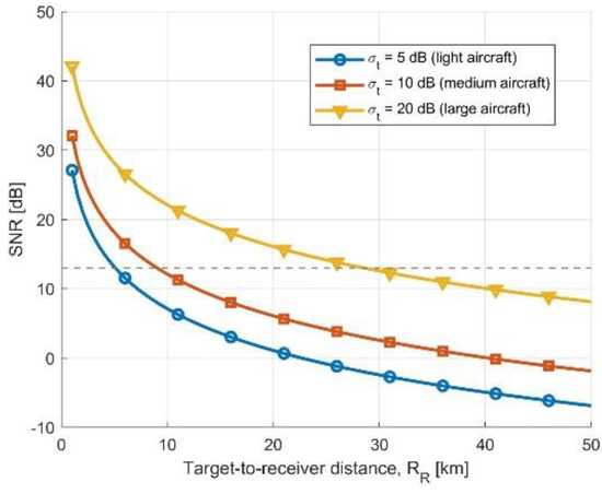
Figure 3.
SNR as a function of range for different target classes assuming a receiving antenna of and a CPI of .
As expected, by assuming a minimum SNR requirement of 13 dB to guarantee an acceptable detection performance, the achievable range coverage is limited to a few kilometres for small targets and below 30 km for large aircraft. Actually, the achievable performance is strictly related to the receiver design strategy. Typical user requirements specify a minimum angular coverage and a corresponding minimum update time. Therefore, given a specific area for the receiving antenna (and, hence, a specific beam size), the CPI will be limited by the need to cover the entire scanning sector in the required update time.
Aiming at some standardization, to analyse the performance independently from the design choices for the receiving system, we consider the required angular coverage in elevation and azimuth , the minimum update time , and we rearrange Equation (3) as
To achieve Equation (4), the antenna gain and integration time have been written as
where and , respectively, indicate the elevation and azimuth beamwidth related to an assumed rectangular antenna of area .
Therefore, the achievable SNR can be evaluated regardless of the design choices on the receiving antenna and the integration time. If the achievable SNR is not sufficient, solutions with multiple simultaneous beams on receive could be considered, either by employing multiple separate antennas or array-based beamforming. In this case, the SNR in Equation (4) can be increased by a factor equal to the number of simultaneous beams
The performance analysis for the considered ATC applications and system classes is carried out according to the specific requirements of range coverage, angular coverage and update time. The results of this analysis are summarized in Table 5. Specifically, by setting a minimum required SNR of 13 dB, we show the resulting minimum number of simultaneous beams on receive that would allow us to satisfy the requirements by exploiting the considered GEO-SAR design. Likewise, we report the additional equivalent isotropic radiated power (EIRP) that would be required on transmit to enable the corresponding ATC bistatic application by exploiting a single receiving beam (staring or scanning).
Table 5.
General requirements for enabling ATC applications.
From the above results, the PAR class of applications proves to be the most feasible, thanks to the lower requirements in terms of angular and range coverage. However, it is worth mentioning that this kind of system might not be of primary interest in the context of civil air traffic control, being most frequently used by military facilities. The SMR systems typically operate at short-range, but they are required to also detect smaller vehicles on the airport surface over a relatively wide angular sector. This results in the need for many simultaneous beams. The ASR application probably represents the most appealing scenario, thanks to the well-known advantages of a passive bistatic system complementing the existing active technologies, although it is penalized by the demanding requirements in terms of range and angular coverage. Anyway, the air surveillance potentialities might still be considered by accepting further relaxations on the performance constraints, in the case of a dense network of sensors, each with a limited assigned coverage. The same applies to the AD radar application. Finally, it may be of interest as an on-board passive radar as a stand-alone solution for CA applications, whose short-range operation makes the concept ideally feasible.
4. Ground Surveillance
Due to its large distance and long integration times, the GEO-SAR system can provide useful information only against persistent scatterers, being incompatible with the typical ground target velocities and surveillance applications. Nevertheless, the continuous availability of a radar illumination from a geostationary emitter over very wide ground areas, opens interesting opportunities for ground surveillance and imaging applications by considering bistatic configurations with lower altitude receivers. Bistatic SAR and GMTI capabilities may be enabled by lightweight and low-cost airborne receivers, exploiting the GEO-SAR as a common illumination source.
4.1. Passive Radar Concept for Ground Surveillance
Even if passive radar research has been primarily focused on the detection and tracking of airborne and maritime targets exploiting stationary ground-based receivers, in the last few years a great interest has been devoted to airborne passive radar systems as a way to enhance the current potentialities of ground monitoring, surveillance and situational awareness, in both defence and civil scenarios. First, theoretical and experimental results have been presented on passive bistatic radars on board a moving platform, aimed at SAR [40,41] and GMTI applications [42,43,44,45,46]. Digital communication signals from ground-based transmitters have been primarily considered. However, such sources are usually characterized by a limited coverage and unfavourable illumination geometries, being easily subject to shadowing phenomena. Moreover, the emitted waveforms are not well suited for conventional clutter suppression strategies, possibly reducing the performance and complicating the signal processing.
In this context, the GEO-SAR transmitter may represent a valuable source for airborne passive radar, providing a very wide area illumination, with a convenient geometry and a pulsed waveform, and opens interesting perspectives for ground surveillance and GMTI applications in several scenarios. Figure 4 sketches the considered system concept. According to the desired coverage, persistence of observation and specific application requirements, different kinds of platforms could be considered, such as conventional aircraft, unmanned aerial vehicles (UAV) or high-altitude platforms (HAPs). Long endurance HAPs or constellations of lightweight receivers might represent an extremely appealing solution for surveillance and reconnaissance applications in the near future, meeting the requirements for long-term monitoring or short revisit times, and could significantly benefit from the advantages of a passive radar sensor.
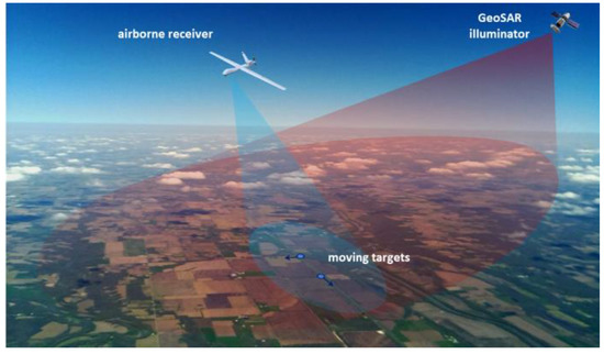
Figure 4.
Concept of GEO-SAR-based passive bistatic radar for airborne ground surveillance applications.
Apart from the more straightforward military and defence applications, several civilian applications can be identified, connected to the capability of detecting, tracking and imaging of ground moving targets. Among them we mention:
- Vehicular traffic monitoring: to control traffic of vehicles, especially in areas where no other kind of systems for this purpose is available, or in critical situations where a backup information system might be required.
- Rail traffic monitoring: to monitor the circulation of trains on railways in critical junctions in case of outage of other kinds of dedicated sensors.
- Borderline and strategic areas’ surveillance: to monitor sensitive areas and detect the possible presence of unauthorized vehicles or people.
- Disaster and crisis management: to increase situational awareness in emergency circumstances, integrate terrestrial segment and support search and rescue vehicles.
The achievable performance, in terms of resolution, coverage and detection capability, would strongly depend on the design and complexity of the receiving system, the acquisition geometry and the platform flight velocity.
A set of potential performance requirements for the mentioned ground surveillance applications are reported in Table 6. Since no specific standard is defined for such scenarios, being the GMTI surveillance more commonly related to the defence sector, the definition of consistent requirements is not straightforward, and our proposal is based on the typical performance of commercial systems and common-sense criteria.
Table 6.
Potential requirements of airborne GEO-SAR-based passive radar for GMTI applications.
4.2. Analysis of Potentialities
Several challenges must be faced for the conceived passive radar system on board an aerial platform to be effective in detecting and localizing potential moving targets, discriminating them from ground clutter. Contrary to stationary operation, the detection of slow-moving targets requires a proper suppression of clutter echoes, which is spread in Doppler due to the relative motion of the receiver with respect to the stationary scene. For this purpose, multi-channel solutions are typically employed, relying on space–time processing techniques [47]. The pulsed waveform of the GEO-SAR illuminator is well suited for these kinds of techniques.
On the other hand, the low available power density might severely limit the range coverage capability and requires relatively long integration times. This may represent an obstacle, especially for airborne receivers flying at high altitudes, with the purpose of wide area surveillance. The long integration times might be limited by potential range and Doppler migration issues, due not only to the target motion characteristics but also to the flight speed and stability of the receiving platform. Further limitations may derive from the expected low PRF adopted by the GEO-SAR transmitter, which may limit the unambiguous Doppler space in the bistatic applications, possibly resulting in ambiguous velocity information and clutter spectral folding. Nevertheless, such effects could be suitably addressed by means of appropriate signal processing techniques.
Let us assume a receiving antenna of area, coherently integrating the echoes of a ground target for a processing interval of . Two classes of carrier platforms are considered: a conventional aerial platform (light aircraft or UAV) flying at an altitude of 4 km and a high-altitude platform (HAP) at an altitude of 20 km.
The achievable SNR for different target classes is reported in Figure 5, as a function of the receiver to target ground range (see Figure 6) corresponding to an incidence angle from 20° to 80°. Typical values of X-band RCS have been assumed for targets, from 0 dBm2 (small ground vehicle) to 15 dBm2 (medium to large ground vehicle). As an order of magnitude, the average RCS of a medium size car oscillates between 0 dBm2 and 7 dBm2, depending on the aspect angle.
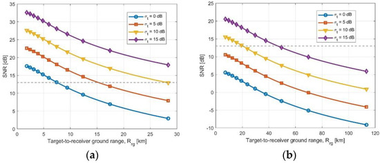
Figure 5.
SNR as a function of ground range for different target RCS assuming receiving antenna and of coherent integration time: (a) from an aircraft at 5 km altitude; (b) from a HAP at 20 km altitude.
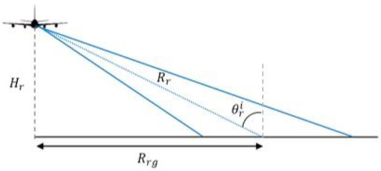
Figure 6.
Airborne receiver acquisition geometry.
Assuming a minimum SNR requirement of 13 dB to guarantee acceptable detection performance in the case of 6 km flight altitude, the achievable ground range may reach 15–20 km from platform nadir for medium class targets, and even more for larger targets. While, for a 20 km altitude platform, ground range coverage below 50 km is ideally obtainable only for large RCS targets. Although the above results may not correspond to the very wide area access capability typically desirable in an airborne surveillance system, the detection of ground targets seems feasible within localized areas, with all the mentioned benefits deriving from the use of a receive-only system.
If a single receiving beam and carrier platform motion are not sufficient to guarantee the coverage of the surveyed area in a given update time, this can be obtained by exploiting multiple beams on receive and/or adopting a beam steering agility. Again, a trade-off exists between the receiving antenna gain and the available integration time.
To define a performance analysis not bound to specific design choices for the receiving system, we refer to a global parameter given by the product of the receiver antenna gain and the coherent integration time. Results in terms of minimum values required to achieve an SNR of 13 dB are shown in Figure 7 as a function of ground range, for 5 km and 20 km platform altitudes and for different target classes.
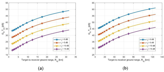
Figure 7.
Minimum required gain as a function of ground range: (a) aircraft at 5 km altitude; (b) HAP at 20 km altitude.
As expected, large gain values are required to compensate for the low available power density and enable target detection at distances such as to justify the use of an aerial platform. To guarantee this minimum required gain, proper design choices should be made for the receiving antenna and integration time, according to the technological limits, payload restrictions, signal processing capabilities and adopted operational strategies.
The feasibility of the potential surveillance applications proposed for a civil scenario is now analysed. The preliminary analysis takes into account the tentative user requirements defined for each application, focusing on the range coverage capability in a worst-case condition (target located at farthest range). The minimum value of gain required to allow target detection at desired range (assuming a minimum SNR of 13 dB) is reported in Table 7, for a platform flying at 5 km and 20 km altitude. Notice that the impact of the receiver altitude on the minimum required gain becomes less relevant in applications involving wide range coverage.
Table 7.
Minimum global gain value to enable the proposed ground surveillance application.
It is evident that a minimum gain above 40 dB is required in all cases. This means that the receiving system should employ, for instance, an antenna of area larger than 1 m2 ( at X-band) and/or coherent integration intervals longer than 1 s.
In conclusion, it can be stated that a GEO-SAR-based passive radar on board an aerial platform may enable ground surveillance applications, with some limitations in terms of extension of the surveyed area. The assumed GEO-SAR system parameters may require non-negligible technological efforts in the receiving system design, especially for long range surveillance applications. Nevertheless, the concept could be extremely appealing for specific kinds of scenarios, providing the benefits of a passive surveillance system, such as covert operations for defence use. In the considered civil scenario, shorter range applications focusing on limited surveyed areas, such as strategic area surveillance and crisis management, could be more easily achievable. Potential additional products could be enabled if an increase in the available power density at ground level was possible.
5. Maritime Surveillance
Keeping the sea environment safe has been one of the biggest challenges of the last few years. Various types of vessels navigate the seas, varying from cruise and trading ships up to vessels involved in nefarious activities such as piracy, human smuggling or terrorist actions. Nowadays, maritime surveillance is essential in order to guarantee the safety of the marine environment and the security of every nation with access to a seashore.
Most of the existing systems tackling maritime traffic safety are based on the use of Automatic Identification System (AIS) transponders, which do not guarantee the monitoring of non-cooperative maritime traffic, often responsible for illegal activities [48]. Radar sensors represent a fundamental asset for improving the safety and security of the maritime domains. Usually, ground-based radar systems monitor the coastal areas, whereas airborne and spaceborne radars survey large, offshore areas. In this section, we define two operative scenarios within which the parasitic exploitation of GEO-SAR signals can represent an appealing alternative solution. In particular, we consider two segments of the maritime environment: open sea and coastal areas.
5.1. Open Sea Surveillance
Open sea surveillance denotes systems and methods providing situational awareness in marine areas far from land, namely in Economic Exclusive Zones (EEZ) or in international waters. The protection of these environments from illegal activities, such as unregulated fisheries and other harmful practices, is essential for both economic and security reasons. However, providing monitoring of such vast areas is difficult. Solutions based on SAR sensors have been proposed [49], but they suffer from the low revisit time allowed by LEO instruments. In this section, we define a novel solution based on a parasitic receiver hitchhiking GEO-SAR signals.
We consider the receiving hardware installed onto a HAP, assumed stationary at a height equal to 20 km above the sea level, collecting the signal reflections from a large offshore area. Figure 8 sketches the system concept. The goal is providing monitoring in a vast offshore area of several tens of nautical miles (NM) [48]. Such a large area is comparable with the size of the GEO-SAR footprint; however, we must assume that one of the transmitting beams is steered toward the maritime area of interest, at least on a periodic basis, with a period suitable for the considered application.
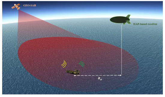
Figure 8.
Concept of GEO-SAR-based passive bistatic radar for open sea surveillance.
The system aims at the detection of moving ships that could belong to very different class types, varying from large vessels such as oil tankers, offshore fishing boats up to small wooden and glass-fiber boats used by traffickers. This large variety, along with the challenging conditions of the system under consideration, make it necessary to define different levels of confidence for the radar detection outputs [50]. To this purpose, we define three different levels of confidence as Low (L), Medium (M) and High (H). Indeed, even though a surveillance system should provide very reliable detections, the presence of small, low observable targets prompts the acceptance of plots less reliable but still useful to enable the detection of the lowest RCS ships. These confidence levels correspond to different objective SNR in Equation (3), particularly equal to 5 dB (L), 9 dB (M) and 13 dB (H). Table 8 lists the assumed levels of confidence for the various classes of targets of interest. It is to be noticed that, even in the case of a low confidence level, performance can be considerably improved considering a successive decision with a tracking stage or resorting to track-before-detect approaches.
Table 8.
Receiving system parameters for open sea surveillance (evaluated at a ground range of 80 NM).
To design the receiving equipment to be installed onto the HAP, it is necessary to quantify the needed antenna gain to assure the nominal performance at the maximum radar range. Here, we assume the farthest target at a ground range distance = 80 NM from the receiver projection on the sea level (see Figure 8). This can be evaluated by making use of Equation (3) considering the SNR objective pertaining to the different confidence levels. For maritime targets under X-band observations, a typical value that can be assumed as upper bound for CPI (to avoid de-correlation effects of the e.m. response) is 1 s. To further stress the operative conditions, we also consider a reduction of 3 dB on the flux power density provided by the GEO-SAR at the footprint centre to consider targets navigating on the edge of the main lobe area. By also assuming a receiver noise figure F = 2 dB, we found the needed values listed in the fourth column of Table 8. Moreover, it is of interest evaluating the area coverage resulting from the exploitation of a single antenna with size able to assure the desired gains. To this purpose, we consider a symmetrical beam in azimuth and elevation and then calculate the corresponding swath in range and azimuth directions, whose resulting values are reported in the last column of the table.
From the analysis above, it is clear as the detection of low RCS targets, even though with degraded performance, is very challenging in the considered scenario, requiring narrow-beam antennas to assure high gains. Consequently, multi-beam receiving antennas or scanning capabilities should be considered to monitor large maritime sections. However, it must be pointed out that most of the offshore vessels usually belong to medium/large RCS classes, such as cargo ships, bulk and container carriers. Short and less reflective ships navigating far from littoral areas are usually small wooden and glass-fiber boats currently used by traffickers for smuggling irregular migrants and illicit drugs. These types of illegal traffics often occur in specific critical areas, where a highly directive beam can be steered for providing situational awareness.
It is also worth stressing that in the analysis we did not consider any further strategy to extend the integration time. However, ships are relatively low speed targets, for which the overall dwell time can be extended by means of combinations of coherent and non-coherent integrations, such as multi-frame [19] and/or track-before-detect [20] approaches, thus allowing increasing of the system performance with slightly increased effort at the processing level.
5.2. Coastal Surveillance
In this section, we put forward a parasitic system leveraging on the GEO-SAR signal for coastal surveillance. Such an application is of particular interest in countries with long shorelines (e.g., Italian shoreline is longer than 7400 km), where national Vessel Traffic System (VTS) networks usually suffer for several gaps that are hard to be filled by active systems due to environmental and legacy issues. Figure 9 sketches the system concept. A receiving-only device is located on the seashore and operates with two RF channels: one for reference, with the antenna pointed to the satellite and recording its direct signal, and the other for surveillance, collecting the reflections from the surveyed area. It is possible that a multitude of receivers could be deployed to extend the coverage over the coast or to perform multi-static operations. In the analysis, unless otherwise specified, we will focus on a single receiving site.
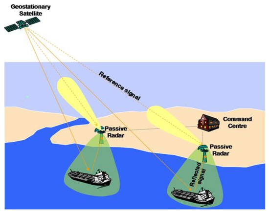
Figure 9.
Concept of GEO-SAR-based passive bistatic radar for coastal surveillance.
The goal of the system is to monitor the littoral traffic in the area going from the shore up to the optical horizon, or at least to the bound of the territorial waters, to ensure the safety and efficiency of ship traffic, to dynamically assess marine risks and plan proper reactions. The monitoring of possible threats must be continuous (24/7 service and independent of the weather conditions), with high refresh rate of the maritime pictures (few seconds). Usually, coverage required by VTS radar equipment must be compliant with the guidelines defined by the International Association of Marine Aids to Navigation and Lighthouse Authorities (IALA) [51]. In particular, detection ranges can be divided into different classes of service: Basic, Standard and Advanced. Table 9 lists the assumed recommendations for range performance for X-band VTS radar systems for the three classes of service. Moreover, the system should be able to discriminate the target with a range resolution of about 30 m (at ranges lower than 5 NM)–75 m (at higher ranges), while angular resolution should be in the order of 1–2°.
Table 9.
Range performance recommendations for VTS radar systems operating in X-band, [51].
Concerning the geometric resolution, the wideband waveforms employed by SAR missions assure a system accuracy compliant with the IALA guidelines, while in azimuth the achievable resolution depends on the particular receiving antenna configuration, as will be discussed later. Concerning the detection ranges, a target belonging to a given class type must be detected with a detection probability PD above a minimum required value while keeping the false alarm rate PFA below a maximum allowed level. These values must be compliant with the role of the system within the VTS service. Typical values for the PD lie in the range 0.7–0.9, while PFA should not exceed 0.1%. In the following, an SNR equal to 13 dB will be considered to meet such criteria. In line with the analysis provided in Section 5.1, the power budget analysis will be carried out assuming a CPI equal to 1 s. While we could assume one of the GEO-SAR beams is centred on the coastal areas to survey, considering the size of the footprint of the GEO-SAR beam we can assume that the littoral area is covered even in the case that the primary applications of the mission require the beam steered over land territories. To take into account such an event, we include a loss of 3 dB in the power budget provided by the transmitter over the sea surface, namely, assuming operation on the edge of the main lobe.
Three possible solutions for the receiver configuration will be analysed and discussed in the following: rotating antenna, staring antenna and multi-beam configuration (see Figure 10).
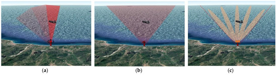
Figure 10.
Possible receiver configurations for coastal surveillance applications. (a) Rotating antenna beam. (b) Staring antenna beam. (c) Array receiver.
5.2.1. Rotating Antenna Beam
Generally, an active coastal radar operates with a narrow-beam antenna put in mechanical rotation to cover the surveyed area, see Figure 10a. While the narrow beam assures a high gain and a fine angular resolution, the rotation imposes a boundary on the CPI, equal to the amount of time a target is illuminated within a scan, referred to as the Time-on-Target, ToT.
Let us assume an antenna having a beamwidth equal to 2° and gain dB rotating with a rotation rate . Obviously, the faster the rotation speed is, the shorter is the ToT. In order to have an insight about the potential coverage achievable with such a configuration, we evaluate the maximum radar range for a target having RCS equal to 100 m2 subsequent to the coherent integration of the pulses within a ToT. The receiver is supposed to operate with a noise figure of 2 dB. Blue ‘□’ markers in Figure 11 denote the resulting maximum radar ranges for different values of the antenna rotation rates. It can be observed that the ranges decrease with the increase in the rotation rate. As an example, a maximum radar range of about 3 NM is achieved for the highest considered rotation speed (22 rounds per minute, rpm), therefore, at ranges much lower than the IALA requirements, even for the Basic class of service (see Table 9). Detection ranges could be increased by binary integrations over multiple scans, but lower rotation speeds should certainly be considered to increase the number of pulses that can be coherently integrated. Nevertheless, slow rotations strongly limit the temporal resolution of the system, which are shown by the red ‘*’ markers in Figure 11. As an example, = 6 rpm imposes a minimum refresh rate of 10 s, which might not be acceptable in high traffic scenarios requiring quick responses. Overall, this configuration seems not to be effective in the system under consideration.
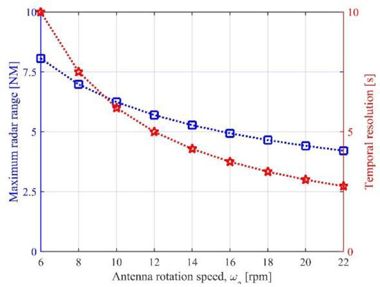
Figure 11.
Maximum radar range (blue) and temporal resolution (red) for coastal surveillance using a rotating antenna beam (RCS = 100 m2).
5.2.2. Staring Antenna Beam
Using a staring antenna beam, Figure 10b, allows signal integration over long dwells, which is particularly suitable for passive radar operations requiring to strengthen sufficiently the received target energy. To assess the coverage performance of this configuration, we assume an antenna with an azimuth beamwidth equal to 25°. Considering antenna length in the elevation dimension such that the whole area can be covered by a single antenna, and also taking into account a realistic antenna efficiency , = 26 dB can be obtained. As above, the noise figure is assumed to be equal to 2 dB.
Figure 12 shows the SNR pertaining to a single frame of duration 1 s as a function of the radar range. Taking 13 dB as objective SNR, we can observe that detection ranges greater than the IALA recommendations are achievable for targets belonging to the 1000 m2 RCS class and greater. For a target with RCS = 100 m2, a maximum radar range of 8 NM could be obtained, therefore, very close to the IALA requirements. Smaller targets (RCS 10 m2, such as sailing boats and small fishing vessels) are hard to detect at ranges required by the IALA. However, the achievable ranges are still of practical interest (e.g., 3 NM for a 10 m2 target); moreover, given the exploitation of a staring antenna, detection performance could be enhanced by resorting to multi-frame integration strategies.
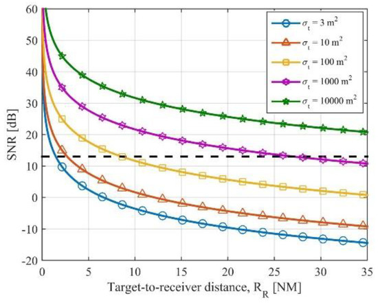
Figure 12.
SNR vs. target-to-receiver range for a coastal radar receiver using a staring antenna beam.
Even though the coverage potentialities can be effective in practical applications, this configuration poses some issues about the angular dimension. First, it is worth noting that while a rotating antenna can cover the full 180°, this is not the case for a staring antenna, whose angular coverage is limited by the need for a high gain. Therefore, a proper trade-off between needed coverage in range and azimuth must be considered depending on the specific user requirements. Moreover, a staring antenna cannot meet the fine angular resolution requirement. Therefore, advanced solutions have to be considered to enable the target angular separation, such as multilateration approaches exploiting multiple receiving sites.
Overall, this configuration can be of practical interest as a gap-filler in areas not covered by active instruments. In particular, it can be an appealing low-cost solution for those coastal areas where overlapping coverage from two or more radar sites is required (as areas subject to high maritime traffic [52]) to guarantee the high levels of reliability and availability required by the VTS authorities.
5.2.3. Multi-Beam Configuration
The performance of the system can be significantly enhanced by resorting to an array of antennas, in lieu of the single-beam configuration. The concept is sketched in Figure 10c: the same surveyed area is covered by means of multiple beams. The passive radar array offers two main improvement factors:
- The coherent integration of the target signal returns received at the antenna elements is expected to provide an increase in the final SNR by a factor K, K being the number of elements of the array.
- The receiving antenna array provides a DOA (Direction of Arrival) estimation capability. Specifically, a target resolution in the angle of arrival can be obtained up to 1/K of the receiving antenna beam, thus allowing the separation of multiple targets potentially present on the same bistatic ellipse. Moreover, a proper estimation can be provided for the target DOA with respect to the receivers, with an accuracy depending on the signal-to-noise conditions.
The design of the array requires setting the number of elements (K) and their spacing (); once they have been set, the azimuth resolution is equal to . Moreover, the spacing of the elements impacts on the position of the grating lobes. In sine space, the array factor is periodic with period : grating lobes can be prevented if is made small enough. In our case, can be set imposing that grating lobes will occur outside of the covered beamwidth.
Let us consider array receiver composed of K = 16 elements with inter-element distance . This implies that: (i) grating lobes occur beyond of steering direction, which is supposed to be sufficiently larger than the antenna beamwidth; (ii) azimuth resolution is about 5°, therefore not too far from the user requirements. Of course, finer resolution can be obtained by using a greater number of elements, which also improves the available SNR.
Table 10 lists the maximum radar range for the different target types along with the results with the single-beam case. Comparing the achieved results with the IALA recommendation in Table 9, we can observe that the array receiver can meet the user requirements, even referring to the Advanced class of service, and also achieving proper angular resolutions with a single receiving site. Therefore, at the price of a more expensive receiver configuration than the single-beam case, this solution is potentially able to be employed as a stand-alone solution for VTS operations.
Table 10.
Maximum radar range for coastal radar system using single/multi-beam configurations.
6. Conclusions
Geosynchronous SAR systems could overcome the revisit time limitations posed by current LEO instruments, with a privileged point of observation of the Earth’s surface. To help this concept to become operative, it is essential to investigate potential applications that might benefit from these instruments. With this objective in mind, in this work we investigated several potential surveillance applications that can be enabled by the parasitic exploitation of the signals emitted by a GEO-SAR satellite.
Table 11 provides a summary of the applications investigated, along with the considered solutions for the receiver design, highlighting for each one its main use and the main benefits provided by the exploitation of GEO-SAR signals. The analysis showed as safety and security services can be enabled by GEO-SAR missions, nicely complementing the scientific applications usually considered, by using properly configured parasitic receivers. This suggests that a wider net of users and stakeholders can be involved in the mission planning to optimize the mission costs.
Table 11.
Summary of potentialities and challenges of the proposed surveillance applications.
Lastly, it is worth stressing that, in this study, we focused on an illuminator with a moderate transmitted power. This heavily affected the parasitic systems’ design, partly limiting their potentialities. Higher transmitted power may allow enhanced performance for surveillance tasks, but at the price of a more expensive GEO-SAR mission design. It is worth noticing that mission design is a complex task, where proper trade-offs between contrasting user needs and design solutions have to be found, also taking into consideration cost optimization. The analysis provided in this work was also aimed at driving the search for the best compromise for the different users’ needs. The next stage of this research is exploring system design solutions to enable both remote sensing and safety and security services.
Author Contributions
Conceptualization and methodology, F.S., G.P.B., D.P., F.C. and P.L.; writing—original draft preparation, F.S. and G.P.B.; writing—review and editing, F.S. and D.P.; funding acquisition, P.L. All authors have read and agreed to the published version of the manuscript.
Funding
The paper is the result of an activity performed in cooperation between Agenzia Spaziale Italiana (ASI) and Sapienza University of Rome, in the frame of GEOSAR project (CUP F43C17000010005).
Informed Consent Statement
Not applicable.
Data Availability Statement
Data sharing is not applicable to this article.
Conflicts of Interest
The authors declare no conflict of interest. The funders had no role in the design of the study; in the collection, analyses, or interpretation of data; in the writing of the manuscript, or in the decision to publish the results.
References
- Tomiyasu, K. Synthetic aperture radar in geosynchronous orbit. In Proceedings of the Antennas and Propagation Society International Symposium, College Park, MD, USA, 15 March 1978; Volume 16, pp. 42–45. [Google Scholar]
- Bruno, D.; Hobbs, S.E.; Ottavianelli, G. Geosynchronous synthetic aperture radar: Concept design, properties and possible applications. Acta Astronaut. 2006, 59, 149–156. [Google Scholar] [CrossRef]
- Hobbs, S.; Mitchell, C.; Forte, B.; Holley, R.; Snapir, B.; Whittaker, P. System design for geosynchronous synthetic aperture radar missions. IEEE Trans. Geosci. Remote Sens. 2014, 52, 7750–7763. [Google Scholar] [CrossRef]
- Monti Guarnieri, A.; Rocca, F.; Ibars, A.B. Impact of atmospheric water vapor on the design of a Ku band geosynchronous SAR system. In Proceedings of the 2009 IEEE International Geoscience and Remote Sensing Symposium, Cape Town, South Africa, 12–17 July 2009; pp. 945–948. [Google Scholar]
- Ruiz-Rodon, J.; Broquetas, A.; Makhoul, E.; Monti Guarnieri, A.; Rocca, F. Nearly Zero Inclination Geosynchronous SAR Mission Analysis With Long Integration Time for Earth Observation. IEEE Trans. Geosci. Remote Sens. 2014, 52, 6379–6391. [Google Scholar] [CrossRef]
- Hobbs, S.; Sanchez, J.P. Laplace plane and low inclination geosynchronous radar mission design. Sci. China Inf. Sci. 2017, 60, 060305. [Google Scholar] [CrossRef]
- Nicolás-Álvarez, J.; Broquetas, A.; Aguasca, A. Precise Orbit Observation Techniques for Geosynchronous Synthetic Aperture Radar (GEOSAR). In Proceedings of the 2019 IEEE International Geoscience and Remote Sensing Symposium, Yokohama, Japan, 28 July–2 August 2019; pp. 8753–8756. [Google Scholar]
- Li, Y.; Monti Guarnieri, A.; Hu, C.; Rocca, F. Performance and Requirements of GEO SAR Systems in the Presence of Radio Frequency Interferences. Remote Sens. 2018, 10, 82. [Google Scholar] [CrossRef]
- Leanza, A.; Manzoni, M.; Monti-Guarnieri, A.; di Clemente, M. LEO to GEO-SAR Interferences: Modelling and Performance Evaluation. Remote Sens. 2019, 11, 1720. [Google Scholar] [CrossRef]
- Madsen, S.N.; Edelstein, W.; DiDomenico, L.D.; LaBrecque, J. A geosynchronous synthetic aperture radar; for tectonic mapping, disaster management and measurements of vegetation and soil moisture. In Proceedings of the 2001 IEEE International Geoscience and Remote Sensing Symposium, Sydney, NSW, Australia, 9–13 July 2001; pp. 447–449. [Google Scholar]
- Wadge, G.; Monti Guarnieri, A.; Hobbs, S.E.; Schulz, D. Potential atmospheric and terrestrial applications of a geosynchronous radar. In Proceedings of the 2014 IEEE Geoscience and Remote Sensing Symposium, Quebec City, QC, Canada, 13–18 July 2014; pp. 946–949. [Google Scholar]
- Melzi, M.; Hu, C.; Dong, X.; Li, Y.; Cui, C. Velocity Estimation of Multiple Moving Targets in Single-Channel Geosynchronous SAR. IEEE Trans. Geosci. Remote Sens. 2020, 58, 5861–5879. [Google Scholar] [CrossRef]
- Guttrich, G.L.; Sievers, W.E.; Tomljanovich, N.M. Wide Area Surveillance Concepts Based on Geosynchronous Illumination and Bistatic UAV or Satellite Reception. In Proceedings of the 1997 IEEE National Radar Conference, Syracuse, NY, USA, 13–15 May 1997; pp. 126–131. [Google Scholar]
- Kuschel, H.; Cristallini, D.; Olsen, K.E. Tutorial: Passive radar tutorial. IEEE Aero. Elect. Syst. Mag. 2019, 34, 2–19. [Google Scholar] [CrossRef]
- Griffith, H.; Baker, C.J. An Introduction to Passive Radar; Artech House: Norwood, MA, USA, 2017. [Google Scholar]
- Zavorotny, V.U.; Gleason, S.; Cardellach, E.; Camps, A. Tutorial on Remote Sensing Using GNSS Bistatic Radar of Opportunity. IEEE Geosci. Remote Sens. Mag. 2014, 2, 8–45. [Google Scholar] [CrossRef]
- Antoniou, M.; Cherniakov, M. GNSS-based passive SAR. In Novel Radar Techniques and Applications; Klemm, R., Nickel, U., Gierull, C., Lombardo, P., Griffiths, H., Koch, W., Eds.; The Institution of Engineering and Technology: London, UK, 2018; Volume 1, pp. 719–766. [Google Scholar]
- Clemente, C.; Soraghan, J.J. GNSS-Based Passive Bistatic Radar for Micro-Doppler Analysis of Helicopter Rotor Blades. IEEE Trans. Aero. Elect. Syst. 2014, 50, 491–500. [Google Scholar] [CrossRef]
- Pastina, D.; Santi, F.; Pieralice, F.; Bucciarelli, M.; Ma, H.; Tzagkas, D.; Antoniou, M.; Cherniakov, M. Maritime Moving Target Long Time Integration for GNSS-Based Passive Bistatic Radar. IEEE Trans. Aero. Elect. Syst. 2018, 54, 3060–3083. [Google Scholar] [CrossRef]
- Santi, F.; Pastina, D.; Bucciarelli, M. Experimental Demonstration of Ship Target Detection in GNSS-Based Passive Radar Combining Target Motion Compensation and Track-before-Detect Strategies. Sensors 2020, 20, 599. [Google Scholar] [CrossRef] [PubMed]
- Stove, A.G.; Gashinova, M.; Hristov, S.; Cherniakov, M. Passive maritime surveillance using satellite communication signals. IEEE Trans. Aerosp. Electron. Syst. 2017, 53, 2987–2997. [Google Scholar] [CrossRef]
- Martelli, T.; Cabrera, O.; Colone, F.; Lombardo, P. Exploitation of Long Coherent Integration Times to Improve Drone Detection in DVB-S based Passive Radar. In Proceedings of the 2020 IEEE Radar Conference, Florence, Italy, 21–25 September 2020; pp. 1–6. [Google Scholar]
- Li, J.; Wei, J.; Cao, Z.; Chen, Q.; Yang, L.; Song, C.; Xu, Z. A DVB-S-Based Multichannel Passive Radar System for Vehicle Detection. IEEE Access 2021, 9, 2900–2912. [Google Scholar] [CrossRef]
- Pisciottano, I.; Santi, F.; Pastina, D.; Cristallini, D. DVB-S based passive polarimetric ISAR—Methods and experimental validation. IEEE Sens. J. 2021, 21, 6056–6070. [Google Scholar] [CrossRef]
- ICAO Annex 10—Aeronautical Telecommunications; Volume 4—Surveillance Radar and Collision Avoidance Systems. Available online: https://store.icao.int/en/annex-10-aeronautical-telecommunications-volume-iv-surveillance-radar-and-collision-avoidance-systems-amendment-no-90-effective-16-7-18 (accessed on 25 November 2021).
- ICAO Global Air Navigation Plan—Framework for Global Planning; d) Surveillance Roadmap. Available online: https://www.icao.int/Meetings/anconf12/IPs/ANConf.12.IP.004.1.1.en.pdf (accessed on 25 November 2021).
- ICAO Global Air Navigation Plan for CNS/ATM Systems, 2nd ed.; Chapter 7 Surveillance Systems. 2002. Available online: https://www.icao.int/publications/Documents/9750_2ed_en.pdf (accessed on 25 November 2021).
- ICAO Guidance Material on Comparison of Surveillance Technologies (GMST), Edition 1.0—September 2007. Available online: https://www.icao.int/APAC/Documents/edocs/cns/gmst_technology.pdf (accessed on 25 November 2021).
- ICAO Manual of Surface Movement Guidance and Control Systems (SMGCS); Doc 9476-AN/927. 1986. Available online: https://store.icao.int/en/manual-of-surface-movement-guidance-and-control-systems-smgcs-doc-9476 (accessed on 25 November 2021).
- EUROCONTROL Specification for ATM Surveillance System Performance (Volume 1 and Volume 2). Available online: https://www.eurocontrol.int/publication/eurocontrol-specification-atm-surveillance-system-performance-esassp (accessed on 25 November 2021).
- EUROCONTROL Standard Document for Radar Surveillance in En-Route Airspace and Major Terminal Areas. Available online: https://www.eurocontrol.int/publication/eurocontrol-standard-radar-surveillance-en-route-airspace-and-major-terminal-areas (accessed on 25 November 2021).
- Kuschel, H.; Ummenhofer, M.; Lombardo, P.; Colone, F.; Bongioanni, C. Passive radar components of ARGUS 3D. IEEE Aero. Elect. Syst. Mag. 2014, 29, 15–25. [Google Scholar] [CrossRef]
- Barott, W.C.; Johnson, M.B.; Scott, K.M. Passive radar for terminal area surveillance: Performance feasibility study. In Proceedings of the AIAA/IEEE Digital Avionics Systems Conference 2014, Colorado Springs, CO, USA, 5–9 October 2014. [Google Scholar]
- Kulpa, K.; Malanowski, M.; Samczyński, P.; Misiurewicz, J.; Smolarczyk, M. On-board PCL systems for airborne platform protection. In Proceedings of the 2011 Tyrrhenian International Workshop on Digital Communications—Enhanced Surveillance of Aircraft and Vehicles, Capri, Italy, 12–14 September 2011; pp. 119–122. [Google Scholar]
- Barott, W.C.; Coyle, E.; Dabrowski, T.; Hockley, C.; Stansbury, R.S. Passive multispectral sensor architecture for radar-EOIR sensor fusion for low SWAP UAS sense and avoid. In Proceedings of the 2014 IEEE/ION Position, Location and Navigation Symposium, Monterey, CA, USA, 5–8 May 2014; pp. 1188–1196. [Google Scholar]
- Palmer, J.E.; Harms, H.A.; Searle, S.J.; Davis, L.M. DVB-T Passive radar Signal Processing. IEEE Trans. Signal Proc. 2013, 61, 2116–2126. [Google Scholar] [CrossRef]
- Colone, F.; Bongioanni, C.; Lombardo, P. Multi-Frequency Integration in FM Radio Based Passive Bistatic Radar. Part I: Target Detection. IEEE Aero. Elect. Syst. Mag. 2013, 28, 28–39. [Google Scholar] [CrossRef]
- O’Hagan, D.W.; Griffiths, H.D.; Ummenhofer, S.M.; Paine, S.T. Elevation Pattern Analysis of Common Passive Bistatic Radar Illuminators of Opportunity. IEEE Trans. Aero. Elec. Syst. 2017, 53, 3008–3019. [Google Scholar] [CrossRef]
- Barott, W.C.; Butka, B. A passive bistatic radar for detection of aircraft using spaceborne transmitters. In Proceedings of the 2011 IEEE/AIAA 30th Digital Avionics Systems Conference, Seattle, WA, USA, 16–20 October 2011. [Google Scholar]
- Gromek, D.; Kulpa, K.; Samczyński, P. Experimental Results of Passive SAR Imaging Using DVB-T Illuminators of Opportunity. IEEE Geosci. Remote Sens. Lett. 2016, 13, 1124–1128. [Google Scholar] [CrossRef]
- Fang, Y.; Atkinson, G.; Sayin, A.; Chen, J.; Wang, P.; Antoniou, M.; Cherniakov, M. Improved Passive SAR Imaging with DVB-T Transmissions. IEEE Trans. Geosci. Remote Sens. 2020, 58, 5066–5076. [Google Scholar] [CrossRef]
- Dawidowicz, B.; Kulpa, K.; Malanowski, M.; Misiurewicz, J.; Samczyński, P.; Smolarczyk, M. DPCA detection of moving targets in airborne passive radar. IEEE Trans. Aero. Elect. Syst. 2012, 48, 1347–1357. [Google Scholar] [CrossRef]
- Wojaczek, P.; Colone, F.; Cristallini, D.; Lombardo, P. Reciprocal-Filter-based STAP for passive radar on moving platforms. IEEE Trans. Aero. Elect. Syst. 2019, 55, 967–988. [Google Scholar] [CrossRef]
- Blasone, G.P.; Colone, F.; Lombardo, P.; Wojaczek, P.; Cristallini, D. Passive Radar DPCA Schemes with Adaptive Channel Calibration. IEEE Trans. Aero. Elect. Syst. 2020, 56, 4014–4034. [Google Scholar] [CrossRef]
- Wojaczek, P.; Cristallini, D.; O’Hagan, D.W.; Colone, F.; Blasone, G.P.; Lombardo, P. A three-stage inter-channel calibration approach for Passive Radar on moving platforms exploiting the minimum variance power spectrum. Sensors 2021, 21, 69. [Google Scholar] [CrossRef] [PubMed]
- Blasone, G.P.; Colone, F.; Lombardo, P.; Wojaczek, P.; Cristallini, D. Passive Radar STAP detection and DOA estimation under antenna calibration errors. IEEE Trans. Aero. Elect. Syst. 2021, 57, 2725–2742. [Google Scholar] [CrossRef]
- Klemm, R. Principles of Space-Time Adaptive Processing, 3rd ed.; The institution of Electrical Engineers: London, UK, 2006. [Google Scholar]
- Ramongassiè, S.; Taveneau, N.; Calmettes, T.; Richard, J.; Challamel, R.; Autran, O.; Foix, V.; Durand, P. Radar and AIS constellation for global maritime surveillance. In Proceedings of the 2010 IEEE International Geoscience and Remote Sensing Symposium, Honolulu, HI, USA, 25–30 July 2010; pp. 3793–3796. [Google Scholar]
- Iervolino, P.; Guida, R. A Novel Ship Detector Based on the Generalized-Likelihood Ratio Test for SAR Imagery. IEEE Trans. Geosci. Remote Sens. 2017, 10, 3616–3630. [Google Scholar] [CrossRef]
- Margarit, G.; Tabasco, A.; Gómez, C. Maritime situational awareness: The MARISS experience. In Proceedings of the ESA SEASAR, Frascati, Italy, 25–29 January 2010; pp. 1–8. [Google Scholar]
- IALA Recommendation V-128 On Operational and Technical Performance Requirements for VTS Equipment, 3rd ed.; International Association of Marine Aids to Navigation and Lighthouse Authorities: Saint Germain en Laye, France, 2007.
- Ristov, P.; Komadina, P.; Tomas, V. Reliability and Availability of the Vessel Traffic Management and Information Systems. Trans. Marit. Sci. 2013, 2, 101–108. [Google Scholar] [CrossRef][Green Version]


Publisher’s Note: MDPI stays neutral with regard to jurisdictional claims in published maps and institutional affiliations. |
© 2021 by the authors. Licensee MDPI, Basel, Switzerland. This article is an open access article distributed under the terms and conditions of the Creative Commons Attribution (CC BY) license (https://creativecommons.org/licenses/by/4.0/).