Abstract
In this study, we improve the matching accuracy of underwater gravity matching navigation. Firstly, the Iterative Optimal Annulus Point (IOAP) method with a novel grid topology is proposed for breaking through the inherent grid structure limit of the canonical gravity matching algorithm and enhancing its underwater gravity matching accuracy. The theory of IOAP is as follows: (1) small-annulus matching and positioning mechanism on the tracking starting point is developed by employing the starting point and drift error of the INS (Inertial Navigation System), the fixed rotation angle, etc. The optimal matching location of the starting point is obtained by matching and comparing the matched points in this small-annulus grid, which contributes to heightening the initial-position error insensitivity of the algorithms. (2) Variable-angle three-layer annulus matching and positioning mechanisms on the tracking ending point were constructed by using the optimal matching location of the starting point and combining the tracking direction-and-distance information of the INS and the cumulative drift error, etc. It is used to generate the annulus matching points with the ring-type grid topology. (3) The optimal matching position of the ending point in this annulus is obtained by iteratively calculating the evaluation index value of the matching points and following the evaluation index optimal rule. Secondly, we comprehensively consider the main performance evaluation indexes of the underwater gravity matching algorithms, such as the statistical indicators of the matching accuracy, the average matching time and the matching success rate, and take them as a basis of the pros and cons of the matching analysis. Furthermore, under conditions that include different scale searching regions or different reference-angle ring radii, the statistical results verify that the IOAP had a different matching ability and better robustness. Finally, several trajectories with the starting points from different areas and the ending points in different gravity ranges are tested and compared to carry out the numerical simulations. These results indicate that the IOAP has many advantages, such as a high matching accuracy and strong positioning applicability in different gravity regions. Compared with the TERCOM (terrain contour matching algorithm), its average matching accuracy was the highest, increased by 40.39%.
1. Introduction
The Inertial Navigation System [1] (INS) is the core navigation system for realizing the autonomous navigation of underwater vehicles. It has the characteristics of short-time high-precision positioning [2]. However, due to the inherent errors of inertial components (such as gyros and accelerometers) and multiple integration of positioning calculations, the INS error is accumulated and diverged over time, which makes it difficult to meet the long-time high-precision positioning target of the underwater vehicle [3]. Therefore, the INS system needs to be calibrated regularly to maintain its navigation accuracy [3]. Moreover, the gravity field information, as one of Earth’s natural geographic attributes, is not easily influenced by uncertain environments, such as climate and sea waves [4]. It usually shows a relative stability for a long time, so the gravity field information is suitable for aiding the INS navigation of underwater vehicles. At present, the gravity aided navigation system is an important technology of underwater INS navigation [5,6] and has become an international hot issue studied by scholars at home and abroad.
An important topic of the gravity-aided INS system is the matching algorithm. Currently, the canonical gravity matching algorithms [7] mainly include the Sandia inertial terrain-aided navigation algorithm (SITAN), the iterative nearest contour point algorithm (ICCP) and the terrain contour matching algorithm (TERCOM [8]). By contrast, the TERCOM has the advantages of simple calculation, insensitivity to the initial error, strong robustness and high positioning accuracy [9], which have widely concerned and been studied by scholars for improving its matching accuracy, efficiency and reliability. On the one hand, in terms of improving the matching accuracy of the TERCOM, Yan et al. [10] presented a new matching algorithm by integrating the TERCOM and ICCP, in which the TERCOM was used to get the initial position, and the ICCP was used for accurate positioning. Tong et al. [11] presented a combined matching algorithm based on local gravity map approximation, which employed the two-dimensional Gaussian basis function for approximating the local gravity reference map and the quasi-Newtonian BFGS nonlinear optimization method for resolving the correlation extremum matching model. In addition, they integrated rough matching based on the TERCOM and measured the data preprocessing based on the difference methods to improve the matching accuracy of the algorithm. Zhao et al. [12] combined the TERCOM with a particle filter and put forward a new terrain-aided navigation algorithm for enhancing the positioning accuracy of the BITAN II algorithm. Zhang et al. [13] came up with an online false matching judgement criterion based on the joint probability of multiple reference points in a correlation plane to settle the mismatching problem that the TERCOM is susceptible to elevation measurement error and terrain similarity. Zhang et al. [14] applied the simulated method of the TERCOM to analyze the influence of major factors on the matching accuracy, such as submarine speed, depth sounding accuracy, initial position deviation, underwater terrain features and digital map resolution. On the other hand, in terms of improving the matching efficiency and reliability of the TERCOM, Han et al. [15] constructed an improved TERCOM by combining the shortest path algorithm and a new correlation analysis algorithm. Soon afterwards, they proposed a new matching algorithm with the mismatching diagnosis method by integrating [9] the spatial sequence constraint and the decision criteria limitation for improving the reliability and matching accuracy of the TERCOM. Li et al. [6] proposed a new hierarchical neighborhood threshold searching method based on the rough–thin matching strategies to improve the matching efficiency of the point-by-point traversal search in the TERCOM. In the same year, they [16] put forward a new geodesic-based method by coupling the shortest arc principle of spherical geometry with the attitude control theory in space and maritime environments to reduce the size of the matching area and improve the matching efficiency of the algorithms. Zhang et al. [17] came up with an underwater terrain matching algorithm based on a line–surface combination to improve the robustness and positioning accuracy of algorithms, in which the TERCOM was selected as the line-matching algorithm, and geometrical similarity was used in the surface matching method.
To sum up, most scholars’ studies have mainly focused on improving the underwater vehicle navigation performance of the TERCOM, but there is little research work on changing the matching grid topology of the TERCOM. Furthermore, the canonical TERCOM does not depend on the starting point location of the underwater vehicle in its trajectory and only takes three times the INS error at the ending point location in the trajectory as the half-side length to span a square-shaped grid matching point matrix. Then, it iterates and searches these pre-matched points to determine the best-matching position of the underwater vehicle. However, this searching mechanism requires a large amount of computation costs and is easy to lead to a low matching efficiency of the algorithms [18]. In addition, the TERCOM also has other shortcomings, including the difficulty in effectively dealing with the observation noise and the process noise [12] and the sensibility of the angle error in the INS range [19]. Therefore, it is necessary to further discuss and research the design problem of grid topology different from that of the TERCOM.
Different from the previous studies, this paper was inspired by the matching grid topology of the TERCOM and the drift error characteristics of the INS, and our main research motivation is the reconstruction of matching grid topology for innovatively proposing the iterative optimal annulus point method (IOAP) with a novel grid topology that aims at improving the matching accuracy of gravity-aided navigation on underwater vehicles. The calculation principle of the proposed IOAP is as follows. The small-annulus matching location mechanism of the trajectory starting point with a ring-type topology was constructed to reduce the sensitivity of the IOAP to the initial location error, in which the INS starting point location is put as the center and the preset drift error and rotation angle are used to span the small-annulus matching grid points. Then, the optimal matching position of the starting point is obtained by following the minimization principle of the gravity absolute deviation value. According to this optimal matching position of the starting point, the central position of the large-annulus matching grid is obtained by recombining the sailing direction-and-distance information of the INS. Simultaneously, the INS cumulative drift error is based on obtaining the number of matched grid rings in the large annulus. Next, the referenced rotated angle of the middle-ring radius and the inner-double and outer-half-based angle principle are employed to establish the ring-shaped distributed topology on these matched grid points and further construct the variable-angle three-layer annulus Matching and Positioning mechanism on the tracking Ending Point (EPMP). In the EPMP, every grid point is used to extract the corresponding gravity sequence from the gravity reference map and then compared with the real measured gravity sequence to calculate the mean square difference (MSD) between them. Afterwards, these MSDs are compared to gain the optimal matched position of the tracking ending point by following the MSD minimization principle.
2. Construction of Iterative Optimal Annulus Point (IOAP) Method with a Novel Grid Topology
The gravity matching navigation algorithm is one of the core components of the underwater vehicle navigation system. Its performance directly determines the positioning effects of the underwater vehicle location calibration, i.e., the positioning accuracy and the matching reliability. Benefitting from the high-precision properties of INS short-time output data [2] and inspired by the matching grid topology of the TERCOM with the INS drift error, the iterative optimal annulus point method (IOAP) with a novel grid topology is proposed to realize the effective search for a high-probability high-precision ring area and improve the positioning accuracy of the TERCOM. Briefly speaking, the calculation principle of the IOAP mainly includes two core modules, namely the Matching Positioning strategy of the tracking Starting Point in small annulus (SPMP) and the Matching Positioning mechanism of the tracking Ending Point in three-layer annulus (EPMP). Their corresponding operations will be described in detail as follows.
2.1. Matching Positioning Strategy of the Tracking Starting Point in Small Annulus (SPMP)
Considering the relative sensitivity [20] of gravity matching algorithms such as the SITAN and ICCP to the initial error of the tracking starting point, the Matching Positioning strategy of the tracking Starting Point in small annulus (SPMP) was established to improve, to a certain extent, the insensitivity (robustness) of the IOAP to the gravity matching initial error. In brief, it is centered around the underwater vehicle position indicated by the INS and uses a certain drift error and rotated angle to span a matched grid area with small annulus topology (termed as small annulus) for covering the real position of the tracking starting point with a probability one. Then, the optimal principle of the gravity-matched indexes on these matched points is evaluated to get the optimal matched location of the tracking starting point.
For the convenience of the mathematical formulation and follow-up description of the algorithms, denote the sampling time margin of a certain trajectory of the underwater vehicle as and the tracking output location sequence of the INS as . Meanwhile, their positioning coordinates and corresponding gravity values in this sequence are marked as and , where represents the sampling sequence length of the INS-indicated trajectory. Thus, the SPMP strategy takes the location coordinate of the INS starting point as the center of the small annulus and sets three times the INS drift error standard deviation with one sampling time margin as the maximum searching boundary radius of the small annulus. Furthermore, if the northeast-rotated angle and the ring radius equally spaced coefficient are set, the total number of matched grid points in small annulus and their positioning coordinates can be calculated and obtained under the SPMP strategy. Figure 1 shows the matched grid points distribution in the small annulus based on SPMP at and .
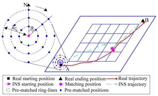
Figure 1.
Matched points distribution in the small annulus based on the SPMP ().
According to Figure 1 and the above parameter settings, the calculation formulation of the coordinate position of the matched grid points in the small annulus of the SPMP can be expressed as follows:
where and denote the horizontal and vertical coordinates of the th grid point on the th small ring, respectively. is the radius of the th ring in the small annulus, where and show the floor, indicates the standard deviation of the INS drift error between two adjacent tracking sampling points (in this paper, the accelerometer is set as 0.01 °/ h, while the gyro is 10−3 m/s2, so the standard deviation of the INS drift error is about 1.8 km/h). represents the rotated angle of the th grid point on each ring in the small annulus, where .
On the basis of the gravity reference map and its grid resolution , the set of matched grid points are obtained for the tracking starting point real position, including the INS tracking starting point position and the SPMP-based grid points position . Then, they are mapped into the gravity reference map point by point, and the gravity value at the nearest grid point from the gravity reference map is taken as the gravity value of the matched point. Therefore, its corresponding expression is as follows:
where shows the gravity value matrix at the grid point position of the gravity reference map, and implies the rounding technique.
In order to determine the optimal matching position of the tracking starting point of the underwater vehicle, the minimizing principle of the gravity absolute deviation value is introduced, and it can be expressed as
where and . It should be noted that is , while is , i.e., the corresponding starting position on the INS.
Remarks: The multimodal phenomenon may occur when multiple grid points in some small scale are projected onto the gravity reference map. Thus, in this paper, it is the first grid point with the minimization of gravity absolute deviation values. In addition, the random selection method can be used as a substitute to get the optimal matched position of the tracking starting point.
The SPMP strategy can realize the effective matched positioning of the tracking starting point of the underwater vehicle with a probability and weaken the sensitivity of IOAP to the initial position error. At the same time, it can also provide the position information of the tracking starting point for further ascertaining the tracking ending point position guided by the INS sailing direction and distance.
2.2. Matching Positioning Mechanism of the Tracking Ending Point in Three-Layer Annulus (EPMP)
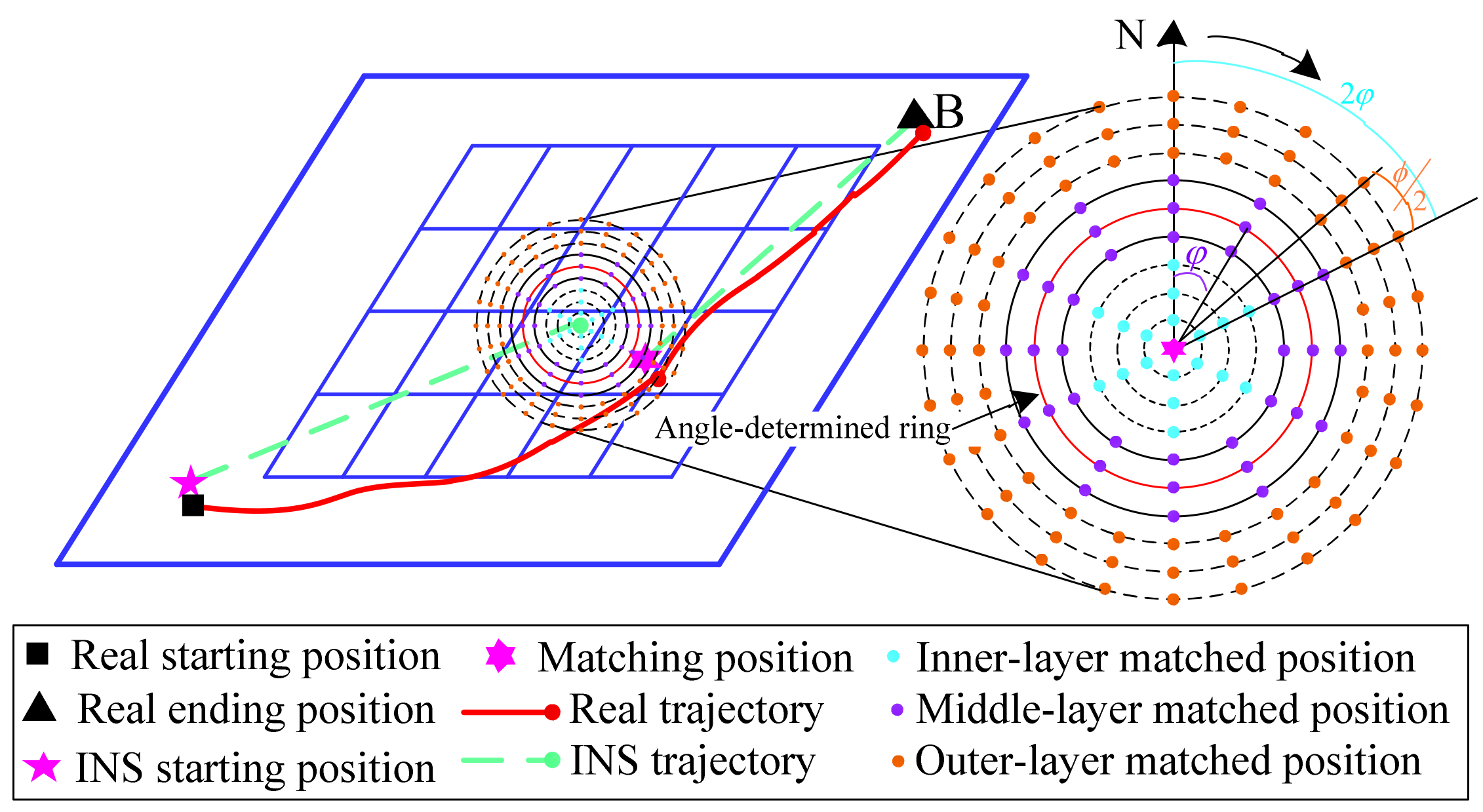
Considering that the INS tracking sequence contains good short-term and high-precision sailing direction and distance information, combining the optimal matched position of the tracking starting point by the SPMP, the central position of the matched domains on the tracking ending point can be further estimated and gotten. Then, the novel matched grid point topology with annulus distribution and its matched positioning mechanism, termed as the Matching Positioning mechanism of the tracking Ending Point in a three-layer annulus (EPMP), is constructed based on the statistical characteristics of the INS drift error. If the standard deviation of the INS cumulative drift error is and the grid resolution of the gravity reference map and the radius of the middle ring are marked as and , respectively, the EPMP can follow the relative relationship among the three constants to obtain the maximum number of rings and the rotated angle between the matched grids in its ring coverage area and further span a large annulus grid with a changed-angle three-layer topological structure (termed as a large annulus) for covering the real position of the tracking ending point with a probability. Then, the coordinate position of every grid point in the EPMP would be mapped into the gravity reference map to extract a gravity sequence of the matched navigational trajectory, which is further compared with the surveyed gravity sequence of underwater vehicles to gain a certain evaluation index (like MSD, i.e., Mean Square Difference) and determine the optimal matched position of the tracking ending point by following the optimal principle of this index (like MSD).
For generating the location coordinates of all matched grid points in the large annulus of the EPMP, it is necessary to get the navigation direction and distance of underwater vehicles based on the tracking starting point and ending point output by the INS system. Then, combining the starting point optimal matched position obtained by the SPMP, the central position of the large annulus can be derived and calculated as the following formulation:
where is the p-norm distance metric between the starting and ending points in the INS trajectory (in this paper, is set to 2, i.e., the corresponding Euclidean distance). shows the sailing radian angle of the positive direction indicated by the abscissa of the coordinate system.
The EPMP consists of several important core parameters, including the central position of the large annulus guided by the INS sailing direction and distance, the maximum search radius of the large annulus set by three times the INS cumulative drift error standard deviation and the scale margin between rings adjusted by the grid resolution of the gravity reference map. Following them, the total number of rings in the large annulus of the EPMP is , where is the ceil. Moreover, if further given a rotated angle between two adjacent grid points on each ring, the matched grid point set based on the EPMP can be calculated and determined. However, the matched grid point generation method of the small annulus in the SPMP is not suitable for the large annulus point generation based on the EPMP, because the fixed can keep the same number of the matched grid points on each ring, which results in the appearance of the phenomenon of “inner denseness and outer sparseness” in grid points obtained by the EPMP; that is, the separation distance between two grid points on the inner ring is too small, while, on the outer ring, is too large. Thus, the changed-angle three-ring grid point topology of the EPMP is designed and introduced, in which the ratio of the grid resolution to the radius of the middle ring is calculated to determine the matched grid point-generated reference angle , and then, the inner and outer rotated angles between adjacent matched points, following the principle of “inner double and outer half”, are set to and to obtain the matched grid point set in the large annulus of the EPMP. Figure 2 shows the distribution diagram of the matched grid point set in the large annulus of the EPMP at and .
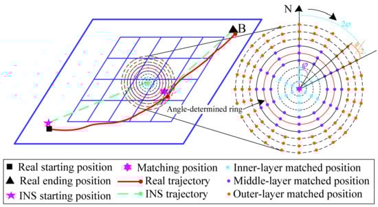
Figure 2.
Distribution diagram of the matched grid points in a large annulus by the EPMP ().
Considering that the normal distribution under natural conditions has a better applicability of the vast majority of systematic errors and its three-sigma rule has a statistically higher probability of covering a character than 99%, three kinds of IOAPs with -EPMP, -EPMP and -EPMP are constructed, termed as -IOAP, -IOAP and -IOAP, respectively, whose total number of rings in their large annulus are denoted by , and , respectively. In addition, since may not be a multiple of three under different principles, and in order to further enhance the good coverage effect of the large annulus grid points by the EPMP on the real location of underwater vehicles, should be adjusted as the following formulation, which contributes to splitting the total rings of the large annulus by the EPMP into the inner, middle and outer three layers:
where indicates the adopted -level principle, and the corresponding radius of rings is .
In order to determine the matched location of the three-layer grid points with the “inner-double and outer-half”-rotated angle, the gird resolution is used as the arc length between two adjacent grid points of the central ring in the large annulus, and the calculation expression of the reference angle for different principles is
where represents the corresponding radius of the central ring in the large annulus under the ith principle, and its formula is . According to Figure 2 and the above parameter settings, following the principle of “inner double and outer half” of the referenced angle with different , the matched grid point position on the inner-middle-outer ring layers in the large annulus of the EPMP can be calculated as
where is the corresponding number of rings in each ring layer under the principle. , and indicate the number of grid point-rotated angles corresponding to the inner layer, the middle layer and the outer layer in the large annulus under the EPMP, respectively.
Given the high accuracy of the gravity value at the grid resolution in the gravity reference map, the reckon gravity value by the interpolation method may not truly reflect the actual gravity value at the matched point position. Thus, the matching process is similar to that of the traditional TERCOM [8], which is performed to determine the best-matched location of the underwater vehicle end point based on the EPMP. Set the total number of matched grid points in the inner, middle and outer three ring layers of the EPMP under a certain specific principle as ; the matched point in the large annulus is firstly taken as the end point of the underwater vehicle tracking sequence (the corresponding position in the gravity reference map) and is then compared with the grid resolution and the grid on the gravity reference map nearest to point , obtained according to the rounding principle. Secondly, the gravity value is taken as the approximation of the gravity value of the matched point. Furthermore, a gravity tracking sequence corresponds to and is extracted by using the approximate grid position of and the sailing speed and direction information of the underwater vehicles. Simultaneously, their nearest neighbor gravity sequence is also obtained on the gravity reference map and compared with the real measured gravity sequence of the underwater vehicle to calculate the matched performance evaluation index. Taking the mean square deviation (MSD) as an example, the matched evaluation index value between them is marked as . Similarly, all matched points in the large annulus of the EPMP are calculated to obtain their evaluation index value, termed as . Thus, following the principle of minimum MSD, the best matched position of the tracking end point of the underwater vehicle can be obtained.
2.3. Implementation Process of Iterative Optimal Annulus Point Algorithm for New Grid Topology
Coupling the SPMP in Section 2.1 with the EPMP in Section 2.2, the IOAP is proposed to realize the effective matching location of the tracking end point of underwater vehicles and, then, to modify the system control parameters of the INS and assist in accomplishing the long-time and long-distance navigation target of the underwater vehicle. In detail, the implementation process of the IOAP is as follows.
Step1: Import the gravity reference map () of the study area, set the tracking starting position, the sailing speed and direction and the number of sampling points and sampling time interval , so as to further calculate and obtain the real position sequence of the simulated track. Moreover, the sailing speed error, the direction error and INS error are set, and the INS position sequence of the simulated track and the gravity value sequence are calculated and obtained.
Step2: The rotated angle and the proportional coefficient of the ring radius in the SPMP mechanism are set to generate the matching grid points at the tracking starting point. Taking three times the INS error at the tracking starting position as the maximum ring radius of the small ring domain, the ring radius of each ring and the rotated angle between the adjacent grid points can be calculated and obtained. Then, the INS starting point is taken as the center of the small ring domain, and each matching grid position in the small ring domain can be determined by Equation (1).
Step3: For each matching grid point in the small ring domain of the SPMP, the gravity value at its nearest grid point is extracted from the gravity reference map by using Equation (2) and used as the matching gravity value of this point . Then, according to Equation (3), the best-matching position of the tracking starting point is obtained by following the principle of minimizing the absolute value of gravity deviation.
Step4: The tracking direction and distance are derived and calculated according to the position relationship between the INS starting point and ending point . Combined with the optimal matching position of the starting point based on the SPMP, the center position of the large ring domain in the EPMP can be obtained by employing Equation (4).
Step5: Following the different principles of the INS errors, the total number of the large ring domains is calculated and achieved with Equation (5), and grid resolution is taken as the span interval between two adjacent ring radii . At the same time, is taken as the arc length between the two adjacent grid points on the inter-ring of the large ring domain, and the reference angle between grid points in the large ring domain can be obtained by utilizing Equation (6).
Step6: Following the ring radius and the principle of “ inner double and outer half “ on referenced angle , each matching grid position of the large ring domain in the EPMP can be obtained according to Equation (7).
Step7: Each matching grid point in the large ring domain of the EPMP is taken as the tracking ending point . The gravity value of the grid position is extracted from the gravity reference map by following the nearest neighbor principle and is the approximate replacement of the gravity value of the matching point . Then, according to the real sailing speed and direction and sampling time interval of the underwater vehicles, a tracking sequence of the matching point is extracted from the gravity map and its corresponding nearest neighbor gravity sequence is calculated, which results in computing the MSD value of this matching point , denoted by .
Step8: For MSDs of all the matching points in the large ring domain of the EPMP, the optimal matching position of the tracking ending point based on the IOAP can be obtained by following the minimization optimization principle.
3. Verification and Application of the Proposed IOAP Algorithm
To test and verify the effectiveness and superiority of the proposed IOAP algorithm in the application of underwater vehicle gravity navigation, three groups of testes are carried out. In detail, Test1 is executed to verify the matched performance difference of the IOAP with different criteria. In Test2, the reference angle calculated by different ring radii is used to examine the different influences on the matched performances of the algorithms. Test3 is performed to demonstrate the good applicability of the proposed IOAP for underwater gravity-matched navigation under different tracking starting points.
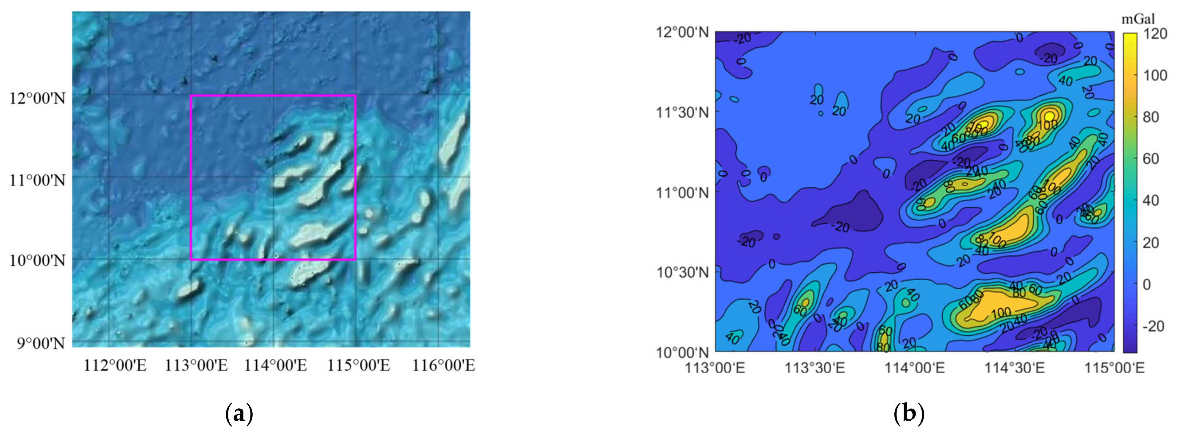
The instance data are sourced from the gravity anomaly data on the San Diego website (http://topex.ucsd.edu/, 10 June 2020) of the University of California, which originally has a resolution. As shown in Figure 3a, the gravity anomaly data in the South China Sea were selected for this paper, in which the longitude and latitude range are 113° E–115° E and 10° N–12° N, respectively. The bilinear interpolation method [21] is employed to transform the gravity anomaly datum data into 100-m × 100-m grid resolution gravity data, as shown in Figure 3b. Statistically the maximum value of the gravity anomaly in this area is 130.57 mGal, while the minimum value is −33.53 mGal, and the average value is 15.43 mGal. All tests were run with Windows 10 (20H2 Version), Intel(R) Core(TM) i7-8565U CPU @ 1.80 GHz 1.99 GHz and Matlab2018a.
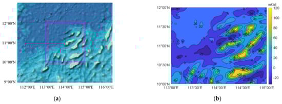
Figure 3.
Schematic diagram of the satellite remote sensing and the gravity reference map in the study area. (a) Satellite remote sensing map and (b) gravity reference map.
3.1. Verification on the Matched Performance Difference of IOAP with Different Criteria
The gravity anomaly grid resolution in the simulated sample block is , and the simulation parameters are set as follows: the accelerometer 0.01 °/h with gyro 10−3 m/s2, the sailing speed 10 m·s−1, the sailing direction northeast 70°, the initial position error 0 m, the velocity error 0.04 m·s−1 and the sailing direction error 0.05°. In addition, the real-time measured data of the gravimeter are the sum of the sampled value in the gravity anomaly reference map and random noise with a standard deviation of 1 mGal, while the number of sampling points and the sampling period are set as 110 and 20 s, respectively. In this paper, suppose that the matching positioning accuracy is defined as /m; the effective matching means that the absolute value difference between the matching position and the real position is located in the closed interval . Thus, if the number of the effective matching of algorithms is in the experimental tests, the matching success rate can be shown as . Meanwhile, the average value (mean), standard deviation (std), worst value (max) of the matching positioning accuracy in times tests and the average matching time T (excluding the simulation environment configuration time) are calculated and recorded as the performance evaluation index of the gravity matching algorithm.
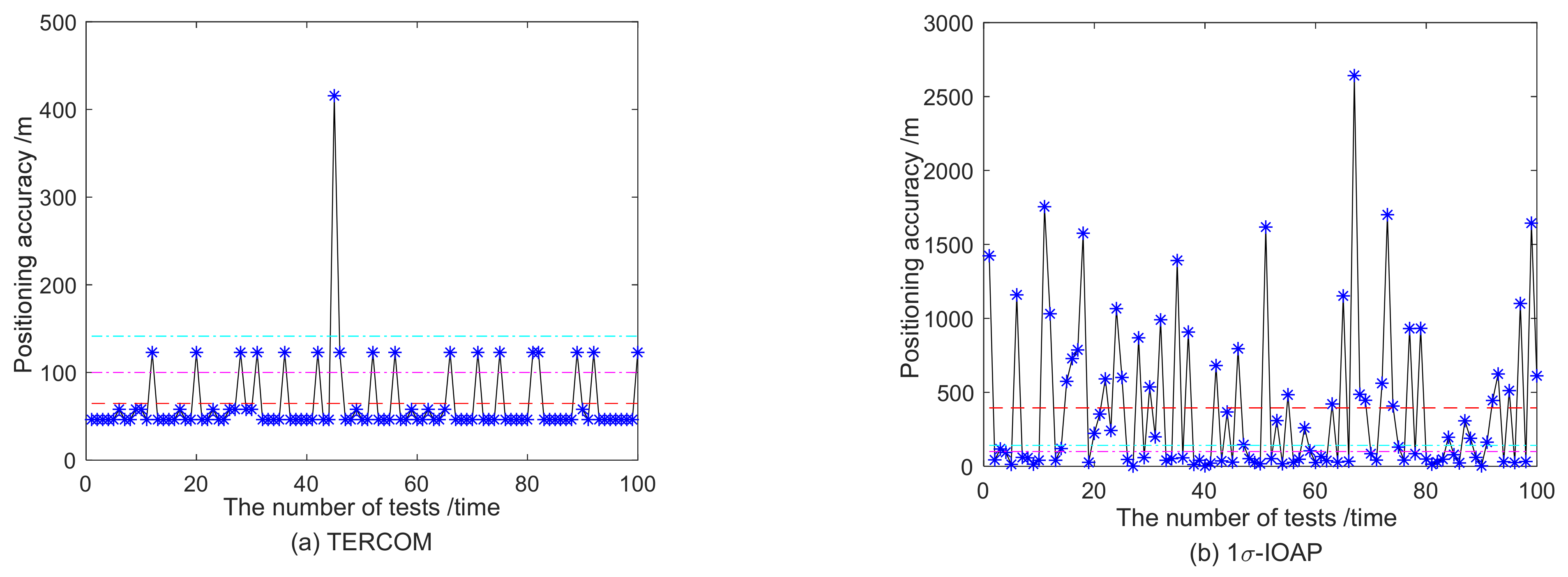
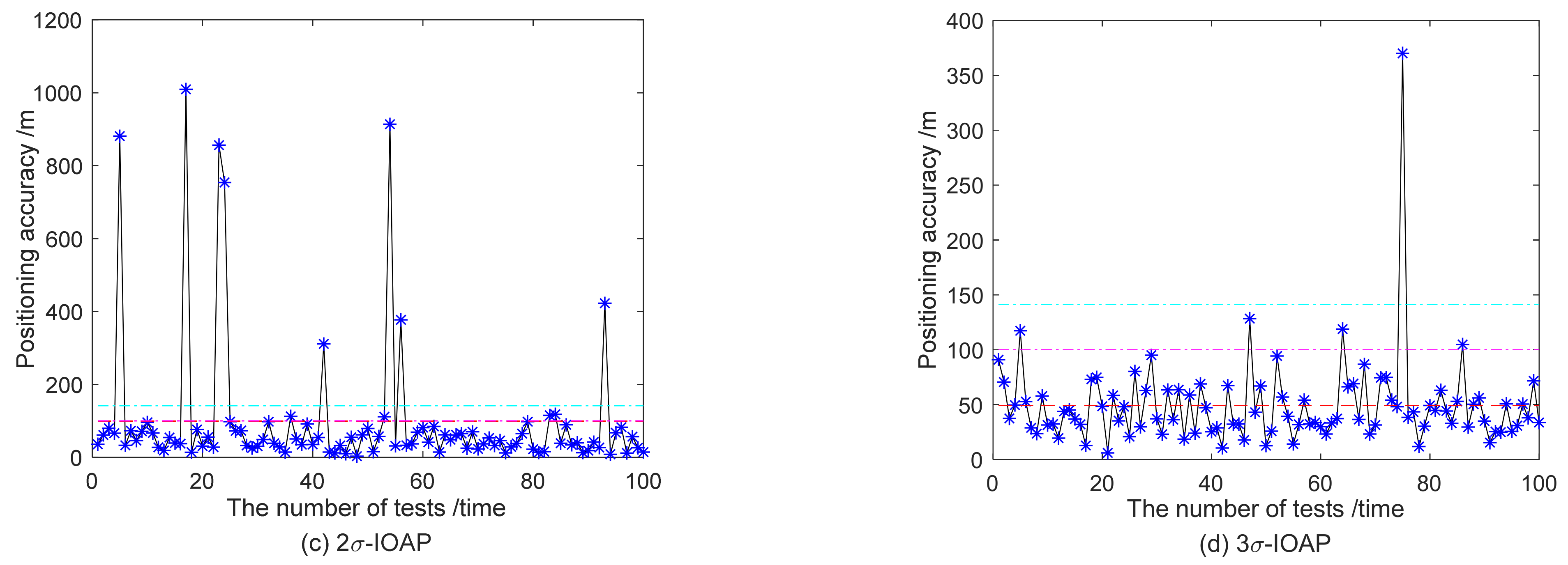
To test and analyze the application performance of IOAPs with different criteria in underwater vehicle gravity matching navigation, 100 times the independent experiments are carried out on 1-IOAP, 2-IOAP and 3-IOAP, while the TERCOM is used as the comparison algorithm. Moreover, the gravity reference map grid coordinates (1400, 1500) are selected as the simulation starting point for underwater vehicle navigation. The statistical results of 100 tests are shown in Table 1, and the compared illustration of the matching positioning accuracy is shown in Figure 4.

Table 1.
Comparison results of the gravity matching algorithms with different criteria.
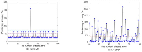
Figure 4.
Comparison of the matching test results of gravity matching algorithms under different A criteria.
As shown in Table 1, the matching positioning performance of the IOAPs is different under the different , where the matching performance of 3-IOAP is the best and significantly better than that of the canonical TERCOM. In terms of the T index, the average running time of 1-IOAP is the smallest, but the matching effect is poor, which results in limiting its effective application in actual underwater vehicle navigation to a certain extent. By contrast, the average running time of 2-IOAP is about half of the TERCOM, its average matching accuracy is less than one grid resolution and the matching probability of 2-IOAP is also better than the TERCOM (88% > 82%) under the condition of positioning accuracy . Consequently, these results show that 2-IOAP has a certain potential navigation application value for the dual target conditions of matching efficiency and accuracy. Furthermore, 3-IOAP has almost the same T-index value as the TERCOM, while its mean, std and max index values on the matching accuracy, as well as the matching success probability, are better than all indexes of the TERCOM and most of the indexes of the other compared algorithms. It was fully demonstrated that the proposed 3-IOAP has a better matching performance and good potential practical value in the gravity-aided navigation of underwater vehicles.
To further analyze the differences of the successful matching effects of the four algorithms under the constraint of different positioning accuracies , the comparison results of the successful matching probabilities for 100 of the tests are shown in Table 2, where the s are set as 20, 40, 60, 80, 100 and 200, respectively. In addition, the comparison histogram is shown in Figure 5.
Table 2.
Comparison results of the successful matching probability /% of four algorithms under different positioning accuracies.
Figure 5.
Comparison histogram of the successful matching probability for four algorithms under different positioning accuracies.
From Table 2, under different positioning accuracy constraints, the successful matching probabilities of -IOAPs are significantly different. Meanwhile, the three -IOAP models have been successfully matched a certain number of times at , but the TERCOM fails. In view of the successful matching probability of algorithms with different positioning accuracies , the matching performance of 3-IOAP is the best, and 2-IOAP is the second-best and better than the traditional TERCOM, but 1-IOAP is weaker than the TERCOM when the positioning accuracy is larger. Figure 5 further intuitively shows the excellent successful matching performance of 3-IOAP. To sum up, the above analysis conclusions still effectively verify the excellent performance of the proposed 3-IOAP in underwater gravity matching navigation.
To further explore and analyze the reasons why 3-IOAP is superior to the TERCOM and other IOAPs on the matching efficiency and accuracy, the scatter comparison graph between the matching position of the TERCOM and the underwater vehicle actual position are plotted as shown in Figure 6 (where the INS positions are used as the origin of image coordinates to ensure that the results of 100 tests can be drawn in the same image).
Figure 6.
The matching and real position comparisons and grid point classification of the TERCOM.
According to Figure 6a, the actual positions of the TERCOM in 100 tests are almost all within the error grid of the INS positions (see the solid-line square outside the dotted-line circle in Figure 6a), and all these positions are also almost located inside the annulus boundary dashed line centered on the INS position (see the dashed-line inscribed circle of the solid-line square in Figure 6a). These results, to a certain extent, show that there are a certain number of small probability-matched points in the rectangular grid of the TERCOM (see the points between the solid-line square and the dashed-line circle in Figure 6b). However, the matched probability of these points outside of the annulus is small but obviously affects the matched efficiency of the TERCOM. Thus, these outer matched points of the annulus are deleted for the gravity matching algorithm, which has no significant effect on the matched efficiency of the algorithms but can effectively improve the matched accuracy, which also indirectly proves the feasibility and effectiveness of designing the grid-matched mechanism based on the annulus topology.
To further analyze the reason why the matched accuracy of 3-IOAP is better than the other -IOAPs, the matched effects of different -IOAPs are drawn in Figure 7.
Figure 7.
Comparison schematic diagrams between the matched and real positions of different-IOAPs.
From Figure 7, it can be seen that the coverage matched effects of IOAPs with different annulus are different for the real positions of underwater vehicles. On the one hand, 3-IOAP realizes the high precision matching positioning of the underwater vehicle by using the grid point coverage of its large annulus. On the other hand, 2-IOAP and 1-IOAP only achieve a good match for the real position, but the optimal matched point for the real position outside the domains is often only scattered on the boundary ring, and it is difficult to find a better matched position, which dramatically affects the matching accuracy of the models. To a certain extent, it further explains the difference of the successful matched probability by employing different IOAPs in Table 1 and Table 2 and the better matched accuracy of 3-IOAP. In summary, 3-IOAP has better and more important potential application value in the gravity matching navigation of underwater vehicles.
3.2. Verification of the Difference Influence on Matching Performance of IOAPs with Different Ring Radius Reference Angle
To further study the effect of the reference angle based on a different ring radius on the matching performance of 3-IOAP, the maximum ring radius of the inner ring layer, the middle ring radius of the “inner-middle” ring layer, the maximum ring radius of the middle ring layer and the middle ring radius of the “middle-outer” ring layer are applied to calculate the reference angle of 3-IOAP, respectively, and then, the corresponding changed-angle three-annulus layer matched grid point sets are generated, in which these models are termed as 1-IOAP, 1.5-IOAP (i.e., 3-IOAP in Section 3.1), 2-IOAP and 2.5-IOAP, respectively. In addition, from Equation (6), it should be remarked that the larger the ring radius , the smaller the reference angle of 3-IOAP, and the more the total number of the generated matched grid points, so, in theory, the matched efficiency of 1-IOAP is the fastest, while the run time of 2.5-IOAP is the slowest.
The parameter settings, including the simulated sample block and the grid coordinates of the tracking starting point, are all the same as Section 3.1. The matching positioning statistical results of 100 independent tests are collected and recorded in Table 3 and Table 4 respectively, where the matched accuracy illustration associated with Table 3 is shown in Figure 8, and the successful matched probability of IOAP in Table 4 is compared and shown in Figure 9.
Table 3.
Comparison of the matched performances of IOAPs with different ring radius reference angles.
Table 4.
Comparison of the matching success probability of IOAPs with different location accuracies (%).
Figure 8.
Comparison on the matching effects of IOAPs with different ring radius reference angles.
Figure 9.
Histogram comparison on the matching success probability of IOAPs with different ring radius reference angles.
From Table 3, the matched accuracy and the matched success rate of 3-IOAP are almost all improved with the increase of the reference angle ring radius . The performance of 2.5-IOAP is the best, followed by 2-IOAP, and the matching effect of 1-IOAP is relatively poor but still better than the TERCTOM in the 5/6 index, which indicates that the reference angle based on a different ring radius will affect the matching performance of 3-IOAP. In view of the T index, the IOAP models with different ring radius reference angles show the phenomenon of “matching efficiency decrease” with the increase of , and the result is consistent with the above theoretical analysis conclusion, which shows that the total number of matched grid points for the different ring radius reference angles are different, which further leads to differences of the matched efficiency. Therefore, in actual applications of underwater vehicle navigation, 3-IOAP for the specific matching target requirements can be properly selected by using the suitable ring radius in order to implement certain specific navigation matching tasks. In summary, the proposed 3-IOAP model in this paper has a higher robustness and better application value for underwater gravity matching navigation.
In a further comprehensive analysis of the results in Table 4 and Figure 9, the matched accuracy of 2.5-IOAP and its success probability under the different scales are almost better than the other IOAPs and TERCOM, but its matching T index value is the highest and almost twice as long as the matched time of the TERCOM. Thus, 2.5-IOAP may be the best choice for the gravity matching algorithm when the underwater navigation objects have no high requirement for the matching efficiency and pay more attention to the matching accuracy. When the bi-objects, including the matched efficiency and accuracy, are required, 1-IOAP is the best choice for the gravity matching algorithm. Therefore, these conclusions further proved that 3 IOAP has a better robustness for underwater gravity matching navigation. In addition, 1.5-IOAP (i.e., 3-IOAP in Section 3.1) shows a better tradeoff effect between the matching efficiency and the matching accuracy and has a considerable matched performance with the TERCOM on the matching efficiency, so the next section will use 1.5-IOAP to further test its good matching performance for different tracking starting points.
3.3. Verification of the Good Matching Performance of IOAP for Different Tracking Starting Points
To further verify the good matching applicability of 1.5-IOAP in the underwater vehicle matching navigation, according to our team’s partitioning results of the suitability area in this researching simulated block [22], three regional grid coordinates, such as A (1660,740), B (1550,740) and C (1400,350), are respectively taken as the tracking starting points of underwater vehicles in this section. The other model parameters are set the same as Section 3.1, and the comparative statistical results of 100 tests are collected in Table 5.
Table 5.
Comparison matching results of IOAPs for different tracking starting points.
As shown in Table 5, under the premise of little differences in the matching efficiency (T index), 1.5-IOAP is significantly better than the traditional TERCOM in the average matching accuracy (mean), the matching accuracy standard deviation (std) and the worst matching accuracy (max). Compared with the TERCOM, the max index values of 1.5-IOAP in the three different starting point situations are improved by 47.24%, 63.96% and 72.16%, respectively, while the mean index values are relatively improved by 20.37%, 40.39% and 13.88%, which shows that the proposed IOAP in this paper has a higher matching accuracy and better synchronous optimizing capacity of multiple tests. On the other hand, for different scales of the successful match, the proposed model shows a relatively superior matching success rate than the TERCOM. Especially when the matching accuracy is less than 40 m, 1.5-IOAP still has a certain probability to successfully achieve the positioning match of underwater vehicles. Thus, these results effectively prove the outstanding matching applicability of the proposed IOAP model for the different domain starting points in the underwater gravity matching navigation.
For intuitively displaying the matching difference effects between 1.5-IOAP and TERCOM in three test positions, a position comparison diagram of the worst match in 100 tests was drawn, as shown in Figure 10.
Figure 10.
Comparison diagram of the matching positions for different tracking starting points.
As shown in Figure 10, 1.5-IOAP, compared with the TERCOM, has a higher matching positioning accuracy for underwater gravity matching navigation with different-domain tracking starting points. Furthermore, since the ending points of these three sailing trajectories are located in different gravity ranges, it is effectively verified that the proposed IOAP algorithm also has good matching adaptability for the different gravity domains, to a certain extent. To sum up, the effectiveness and reliability of the IOAP based on the new grid topology are full demonstrated to improve the gravity matching accuracy of underwater vehicles.
4. Conclusions
In this paper, an iterative optimal annulus point model with a novel grid topology was proposed to improve the matching accuracy of underwater gravity-aided navigation.
- (1)
- The construction of an iterative optimal annulus point model with a novel grid topology. On the basis of breaking out from the traditional square-shaped grid topology of the TERCOM, the annulus-shaped topology of the matching grid points was constructed. Then, the Matching Positioning strategy of the tracking Starting Point in small annulus (SPMP) and the Matching Positioning mechanism of the tracking Ending Point in three-layer annulus (EPMP) were proposed by employing the INS sailing direction and distance information. Furthermore, an iterative optimal annulus point model with a novel grid topology was constructed by coupling the SPMP and EPMP.
- (2)
- The optimization selection of the criterion and the reference angular ring radius for the optimal matching navigation in the large annulus at the tracking ending point. In this paper, the matching evaluation indexes, such as the average matching accuracy, matching standard deviation, average matching time and matching success rate, were comprehensively compared. These evaluation indexes were taken as the selection basis of the model parameters, which resulted in verifying the different influences of the parameters on the matching performances of the proposed iterative optimal annulus point algorithm and realizing the selection of good parameters to improve the underwater gravity matching accuracy.
- (3)
- The improvement of the underwater matching navigation accuracy. For the matching performance testing in three regions, the results showed that the iterative optimal annulus point model with a novel grid topology, compared with the TECOM, had little difference of the average matching time. The worst matching accuracies of the proposed model were also improved by up to 47.24%, 63.96% and 72.16%. Simultaneously, the average matching accuracies of the iterative optimal annulus point model were increased by up to 20.37%, 40.39% and 13.88%, respectively. In summary, the iterative optimal annulus point model with a novel grid topology contributed to enhancing the matching accuracy of underwater vehicle gravity matching navigation.
Author Contributions
Conceptualization, S.Z., W.Z. and Z.L.; data curation, S.Z.; formal analysis, S.Z. and Z.L.; funding acquisition, W.Z.; software, S.Z. and Z.L.; writing—original draft, S.Z. and writing—review and editing, S.Z., W.Z., Z.L., A.X. and H.Z. All authors have read and agreed to the published version of the manuscript.
Funding
This work was supported by the China Postdoctoral Science Foundation under grants 2021M701537, the National Natural Science Foundation of China under grants 41774014 and 41574014, the Liaoning Revitalization Talents Program under grant XLYC2002082, the Frontier Science and Technology Innovation Project and the Innovation Workstation Project of Science and Technology Commission of the Central Military Commission under grant 085015 and the Outstanding Youth Fund of China Academy of Space Technology.
Acknowledgments
We greatly appreciate the helpful suggestions from the editors and anonymous reviewers.
Conflicts of Interest
The authors declare no conflict of interest.
References
- Wang, C.; Wang, B.; Deng, Z.; Fu, M. A Delaunay Triangulation-Based Matching Area Selection Algorithm for Underwater Gravity-Aided Inertial Navigation. IEEE/ASME Trans. Mechatron. 2020, 26, 908–917. [Google Scholar] [CrossRef]
- Wang, B.; Zhu, J.; Deng, Z.; Fu, M. A characteristic parameter matching algorithm for gravity-aided navigation of underwater vehicles. IEEE Trans. Ind. Electron. 2018, 66, 1203–1212. [Google Scholar] [CrossRef]
- Jeon, H.C.; Park, W.J.; Park, C.G. Grid design for efficient and accurate point mass filter-based terrain referenced navigation. IEEE Sens. J. 2017, 18, 1731–1738. [Google Scholar] [CrossRef]
- Lee, C.; Oh, J.; Hong, C.; Youn, J. Automated generation of a digital elevation model over steep terrain in Antarctica from high-resolution satellite imagery. IEEE Trans. Geosci. Remote Sens. 2014, 53, 1186–1194. [Google Scholar] [CrossRef]
- Zheng, W.; Hu, H.Z.; Zhong, M.; Yuan, M.J.; Zhou, X.H.; Bang, B.B. Efficient and rapid estimation of the accuracy of future GRACE Follow-On Earth′s gravitational field using the analytic method. Chin. J. Geophys. 2010, 53, 796–806. [Google Scholar] [CrossRef]
- Li, Z.; Zheng, W.; Wu, F.; Fang, J. Improving the matching efficiency of underwater gravity matching navigation based on a new hierarchical neighborhood threshold method. Chin. J. Geophys. 2019, 62, 2405–2416. [Google Scholar]
- Park, J.; Park, Y.G.; Park, C.G. Parameter Estimation of Radar Noise Model for Terrain Referenced Navigation Using a New EM Initialization Method. IEEE Trans. Aerosp. Electron. Syst. 2019, 56, 107–112. [Google Scholar] [CrossRef]
- Golden, J.P. Terrain contour matching (TERCOM): A cruise missile guidance aid. In Image Processing for Missile Guidance; International Society for Optics and Photonics: Bellingham, WA, USA, 1980; Volume 238, pp. 10–18. [Google Scholar]
- Han, Y.; Wang, B.; Deng, Z.; Wang, S.; Fu, M. A mismatch diagnostic method for TERCOM-based underwater gravity-aided navigation. IEEE Sens. J. 2017, 17, 2880–2888. [Google Scholar] [CrossRef]
- Yan, L.; Cui, C. A new algorithm of gravity matching aided navigation. In Second International Conference on Space Information Technology; International Society for Optics and Photonics: Bellingham, WA, USA, 2007; Volume 6795, p. 679529. [Google Scholar]
- Tong, Y.D.; Bian, S.F.; Jiang, D.F.; Xiang, C.B. A new integrated gravity matching algorithm based on approximated local gravity map. Chin. J. Geophys. 2012, 55, 2917–2924. [Google Scholar]
- Zhao, L.; Gao, N.; Huang, B.; Wang, Q.; Zhou, J. A novel terrain-aided navigation algorithm combined with the TERCOM algorithm and particle filter. IEEE Sens. J. 2014, 15, 1124–1131. [Google Scholar] [CrossRef]
- Zhang, K.; Wang, K. Judgement criterion for terrain false matching based on joint probability of multiple reference points. J. Beijing Univ. Aeronaut. Astronaut. 2018, 44, 1562–1568. [Google Scholar]
- Zhang, J.; Xu, Z.; Wang, X. Research on error of underwater terrain aided navigation based on TERCOM algorithm. J. Nav. Univ. Eng. 2020, 32, 44–49. [Google Scholar]
- Han, Y.; Wang, B.; Deng, Z.; Fu, M. An improved TERCOM-based algorithm for gravity-aided navigation. IEEE Sens. J. 2016, 16, 2537–2544. [Google Scholar] [CrossRef]
- Li, Z.; Zheng, W.; Wu, F. Geodesic-based method for improving matching efficiency of underwater terrain matching navigation. Sensors 2019, 19, 2709. [Google Scholar] [CrossRef] [PubMed] [Green Version]
- Zhang, L.; Liu, X.; Jia, S.; Yan, S. A line-surface integrated algorithm for underwater terrain matching. Acta Geod. Cartogr. Sin. 2020, 2, 10–20. [Google Scholar]
- Zhang, J.; Zhang, T.; Shin, H.S.; Wang, J.; Zhang, C. Geomagnetic gradient-assisted evolutionary algorithm for long-range underwater navigation. IEEE Trans. Instrum. Meas. 2020, 70, 1–12. [Google Scholar] [CrossRef]
- Dai, T.; Miao, L.; Shao, H.; Shi, Y. Solving gravity anomaly matching problem under large initial errors in gravity aided navigation by using an affine transformation based artificial bee colony algorithm. Front. Neurorobot. 2019, 13, 1–11. [Google Scholar] [CrossRef] [PubMed]
- Han, Y.; Wang, B.; Deng, Z.; Fu, M. A combined matching algorithm for underwater gravity-aided navigation. IEEE/ASME Trans. Mechatron. 2017, 23, 233–241. [Google Scholar] [CrossRef]
- Liu, Y.; Zhang, G.; Huang, Z. Study on the Arctic Underwater Terrain-Aided Navigation Based on Fuzzy-Particle Filter. Int. J. Fuzzy Syst. 2021, 23, 1017–1026. [Google Scholar] [CrossRef]
- Li, Z.; Zheng, W.; Fang, J.; Wu, F. Optimizing suitability area of underwater gravity matching navigation based on a new principal component weighted average normalization method. Chin. J. Geophys. 2019, 62, 3269–3278. [Google Scholar]
Publisher’s Note: MDPI stays neutral with regard to jurisdictional claims in published maps and institutional affiliations. |
© 2021 by the authors. Licensee MDPI, Basel, Switzerland. This article is an open access article distributed under the terms and conditions of the Creative Commons Attribution (CC BY) license (https://creativecommons.org/licenses/by/4.0/).