1. Introduction
Spaceborne synthetic aperture radar (SAR) systems are used to provide weather and daytime independent images of the earth. These images are obtained from the backscattering properties of the region illuminated by the frequency chirp of the SAR system [
1] (pp. 6–7). In order to obtain correct physical quantities, such as the radar cross section (RCS) and the backscattering coefficients, the whole SAR system has to be calibrated against reference targets with known RCS, which can be passive and active targets.
Active targets, which are referred to as transponders, are able to receive, amplify, and retransmit the SAR signal. By doing so, they appear as bright spots in the imaged region. As their RCS is accurate and stable, they are used as a reference for the external calibration of SAR systems. In addition to this, polarimetric capabilities of SAR systems require fully polarimetric transponders to determine the complete backscattering matrix of the system [
2].
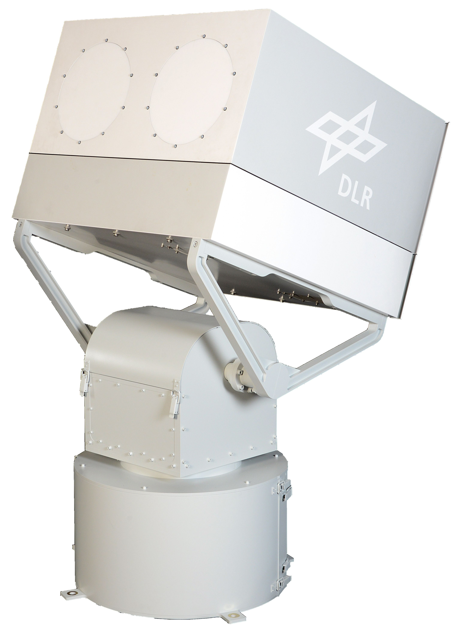
The German Aerospace Center (DLR) has been developing, building, and operating accurate transponders for more than 20 years. These are based on a two-antenna concept, where one antenna is used to receive the SAR signal and the second antenna is used to retransmit the amplified signal. Using this concept, a variable time delay between the signals’ reception and re-transmission can be introduced. In between, the SAR signal can be recorded to obtain additional information, such as the satellite’s beam pattern, its pointing, or pulse characteristics. A further advantage of the two-antenna concept is the possibility of providing different receive and transmit polarizations. The antennas and electronics are contained in a temperature stabilized housing, as shown in
Figure 1. In order to achieve the aim of an all year round outdoor operation, a compact transponder and, consequently, antenna design are prerequisites.
When operating two antennas simultaneously and in close proximity of each other, the antenna coupling has to be considered as an interfering factor. As an electronic amplification of the incident signal takes place in the transponder, the coupling has to be reduced to a minimum to avoid measurement errors and the escalation of the transponder system.
A new generation of transponders is currently in development at DLR for future fully polarimetric SAR missions operating in L-band. As one of the key influences on the transponder design, the antenna coupling of the newly developed L-band antennas was investigated and the results will be presented in this paper.
2. L-Band Antenna
The antenna developed for the compact transponder design in L-band is referred to as a VEGA antenna, which is an abbreviation of the German equivalent to the choked Gaussian horn antenna. The antenna is dual-polarized, which means it is able to receive or transmit two polarizations—horizontal and vertical [
3].
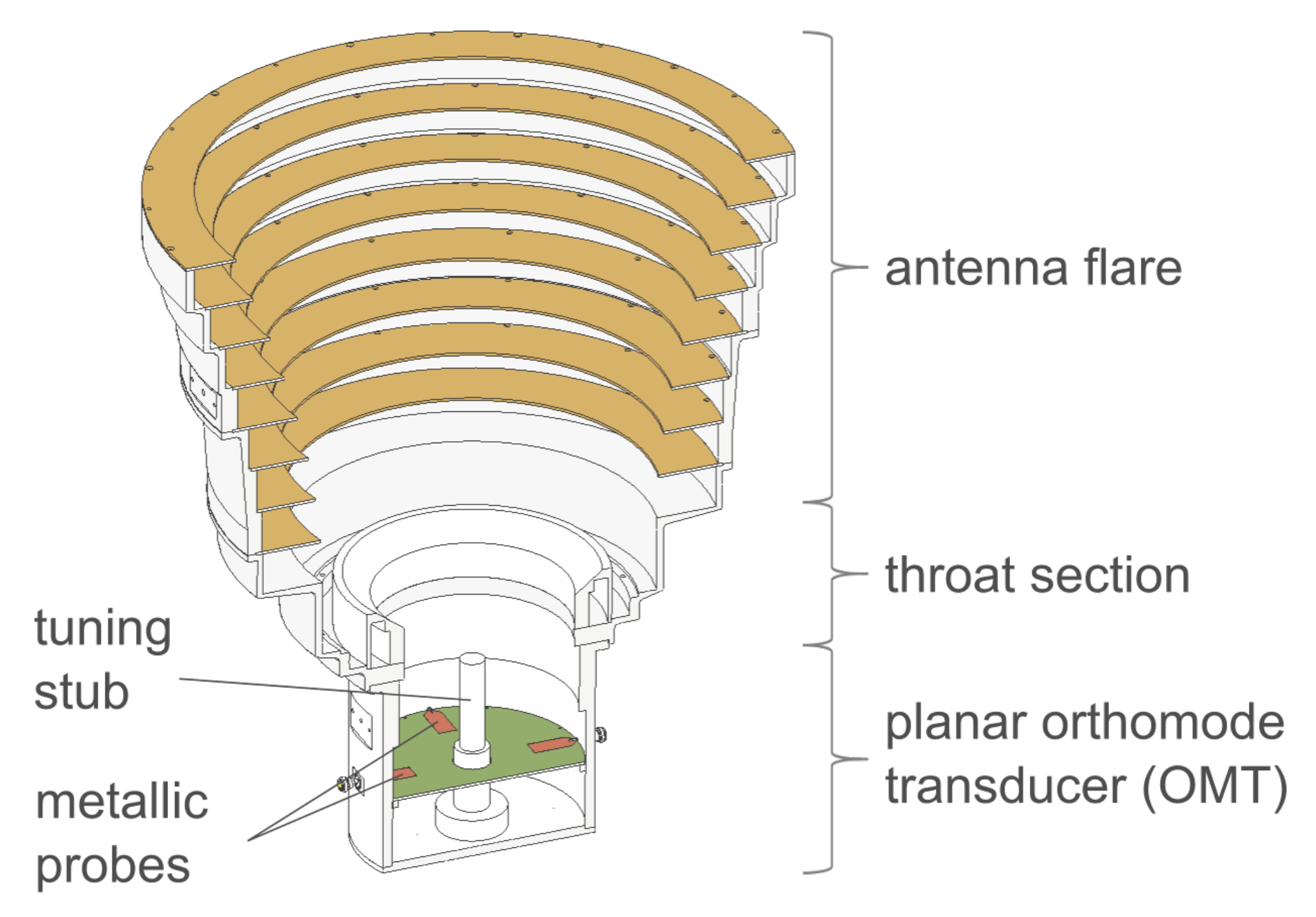
Structurally, the VEGA antenna can be separated into three parts. The antenna flare, its throat section, as well as its planar orthomode transducer (OMT) as shown in
Figure 2.
The antenna has an overall height of
and a maximum diameter of approximately
. The OMT is responsible for generating a TE
mode, which is transformed into a hybrid mode by the throat section. Through the antenna flare, the hybrid mode will be coupled into free space as a Gaussian beam mode with linear polarization [
4].
In order to generate the TE
mode within the OMT, two metal probes opposite of each other have to be fed simultaneously with the same signal but with an induced 180
phase difference between the probes’ inputs. This is achieved by utilizing a so-called feed-network. The main part of the feed-network is a 3 dB 180
hybrid coupler, which is able to equally split an input signal in between its two outputs while introducing a 180
phase shift between the two outputs. To fine tune the inputs into the antenna additional variable attenuators and phase shifters are used [
5] (pp. 30–32). To realize their dual-polarization capability, each antenna has to utilize two feed-networks, and is therefore able to generate two orthogonal linear polarizations. These polarizations will be referred to as horizontal and vertical polarization.
Each transponder will be outfitted with two antennas, which have been designed to be compact and whose antenna flares are specifically manufactured out of carbon-reinforced-polymer (CFK) to reduce weight (see
Figure 3 and
Figure 4).
3. Coupling Parameters
Previous DLR transponder designs are based on single-polarized antennas, which are operated with a 90
polarization offset to each other. Therefore, the best possible polarization mismatch and decoupling of the antennas is realized [
6]. With the newly developed antennas for L-band it is possible to receive and to retransmit a horizontal and vertical polarization. The reception may partially take place simultaneously to the re-transmission of the signal. This, in turn, means a polarization offset of 90
between the receiving and transmitting antenna is not always possible, and the resulting coupling of the antennas becomes critical. In addition to investigating said coupling, possible measures to reduce the antenna coupling have to be tested to realize a compact two-channel transponder.
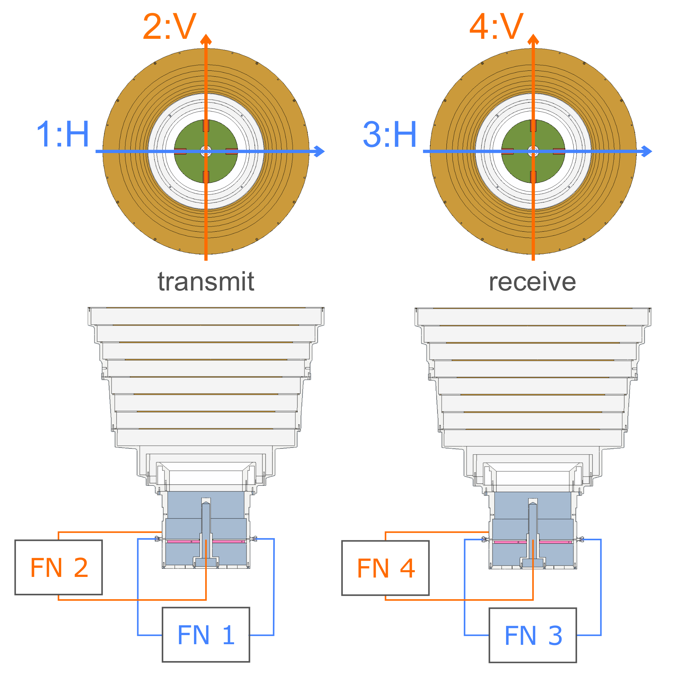
In order to properly characterize the mutual antenna coupling between the two VEGA antennas, coupling parameters have been defined on the underlying idea of common s-parameters referencing the numeration in
Figure 5. This numeration corresponds to the enumeration of the feed-networks (FN) used in the setup. S
represents the received signal at the output of the feed-network with the number r when a signal is transmitted using the feed-network number t.
This leads to several definitions regarding the antenna coupling, which are listed in
Table 1. A RX-TX polarization set consisting of parallel polarizations is referred to as co-coupling, while a set of perpendicular polarizations is referred to as cross-coupling. The antenna cross-talk is defined separately for each antenna.
Assumptions regarding the severity of the mutual antenna coupling can be based on the behavior of the polarization mismatch. Additionally, it can be expected that the mutual coupling will decrease, the further the antennas are apart.
Taking into account the design of the transponder, the targeted RCS, the intrinsic amplification, and the antenna gain, the requirements consist of realizing an antenna decoupling of at least 90 dB and to find the minimal distance between the antennas at which this decoupling magnitude is reached.
4. Simulations and Measurements
To obtain a first estimate on the mutual coupling of the dual-polarized VEGA antennas, a simulation setup using Altair® Feko® was developed, which was closely based on the physical implementation. This means that the dual feeding system was implemented through the use of ideal hybrid couplers to allow for the correct feeding of the antenna inputs. A total of 50 Ω terminations were placed at the unused ports of the hybrid couplers.
The verification of the dual feeding antenna was obtained through comparison of a single antenna simulation setup with a compact test range (CTR) measurement of the antenna and its feeding system. Specifically, the simulated antenna radiation pattern, the reflections at the input ports, as well as the coupling between both polarization channels were compared to the actual measurement results. For the reflections and cross-talk the range of magnitude and overall trend could be verified. In addition to that, the co- and cross-polarization gain patterns showed good agreement between the simulation and measurement [
5] (pp. 41–44).
The complete coupling simulation setup consisted of two VEGA antennas and four feed-networks in total. The distance between both antennas, always measured from one antenna center to the other, increased from up to 3 .
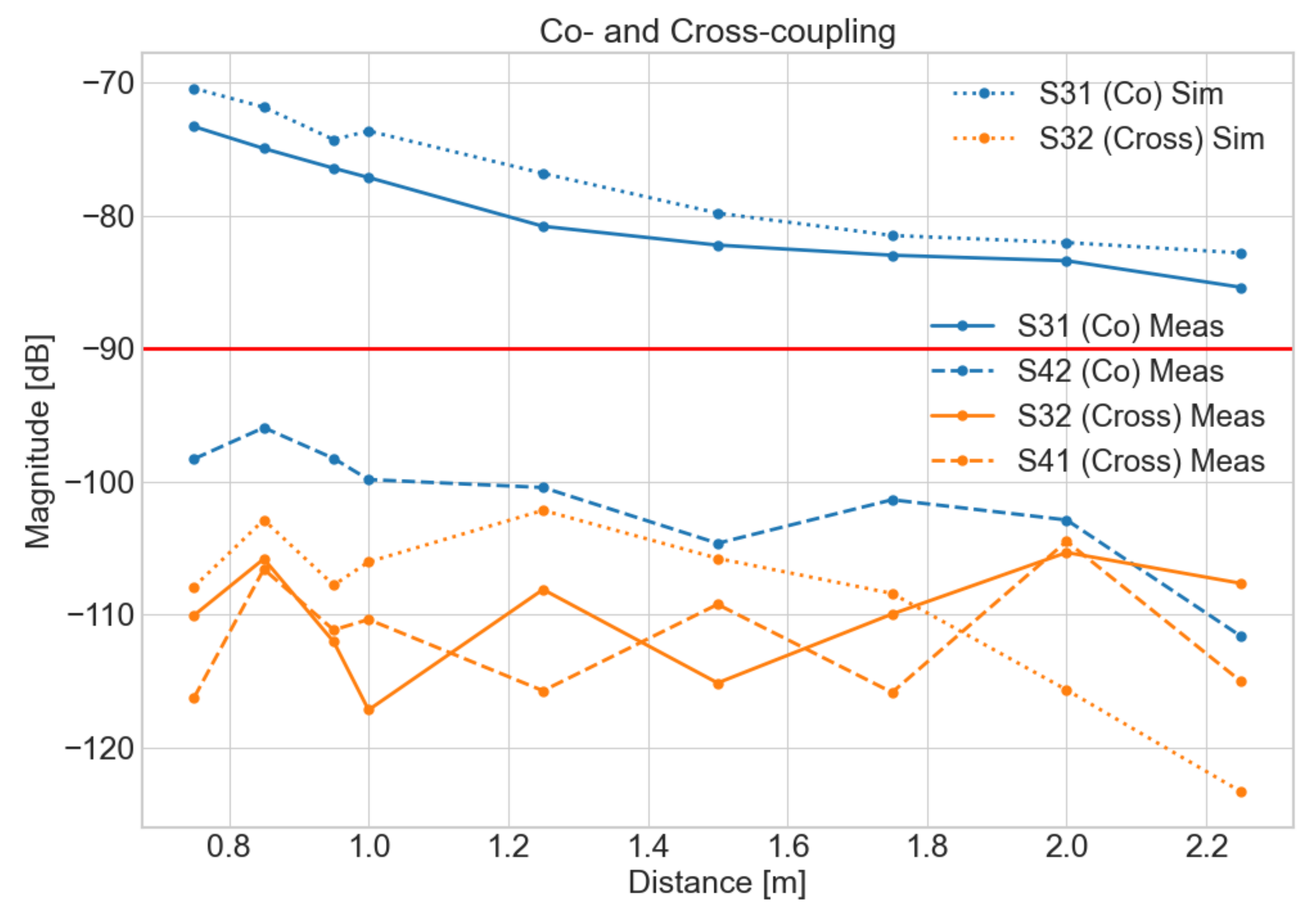
As is shown by the dotted data set in
Figure 6, the initial assumptions were confirmed by the simulation results. The overall trend of a decrease in the antenna coupling with an increase of the antennas’ distance can be observed. In addition, the simulated cross-coupling magnitude is about 30 dB lower than the simulated co-coupling magnitude for all distances due to the polarization mismatch. Therefore, the co-coupling parameters S
and S
were chosen as the determining worst case coupling parameters and were investigated further.
Although S and S are both co-coupling parameters, additional simulation results had indicated that the HH polarization set would be the worst case coupling scenario. Therefore, we expected S to be the single determining parameter for realizing the decoupling goal of 90 dB.
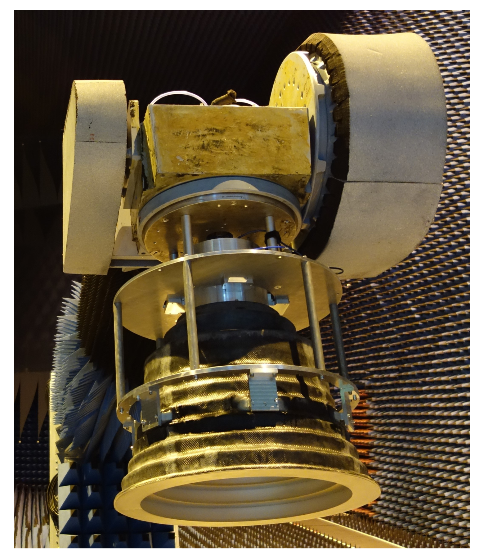
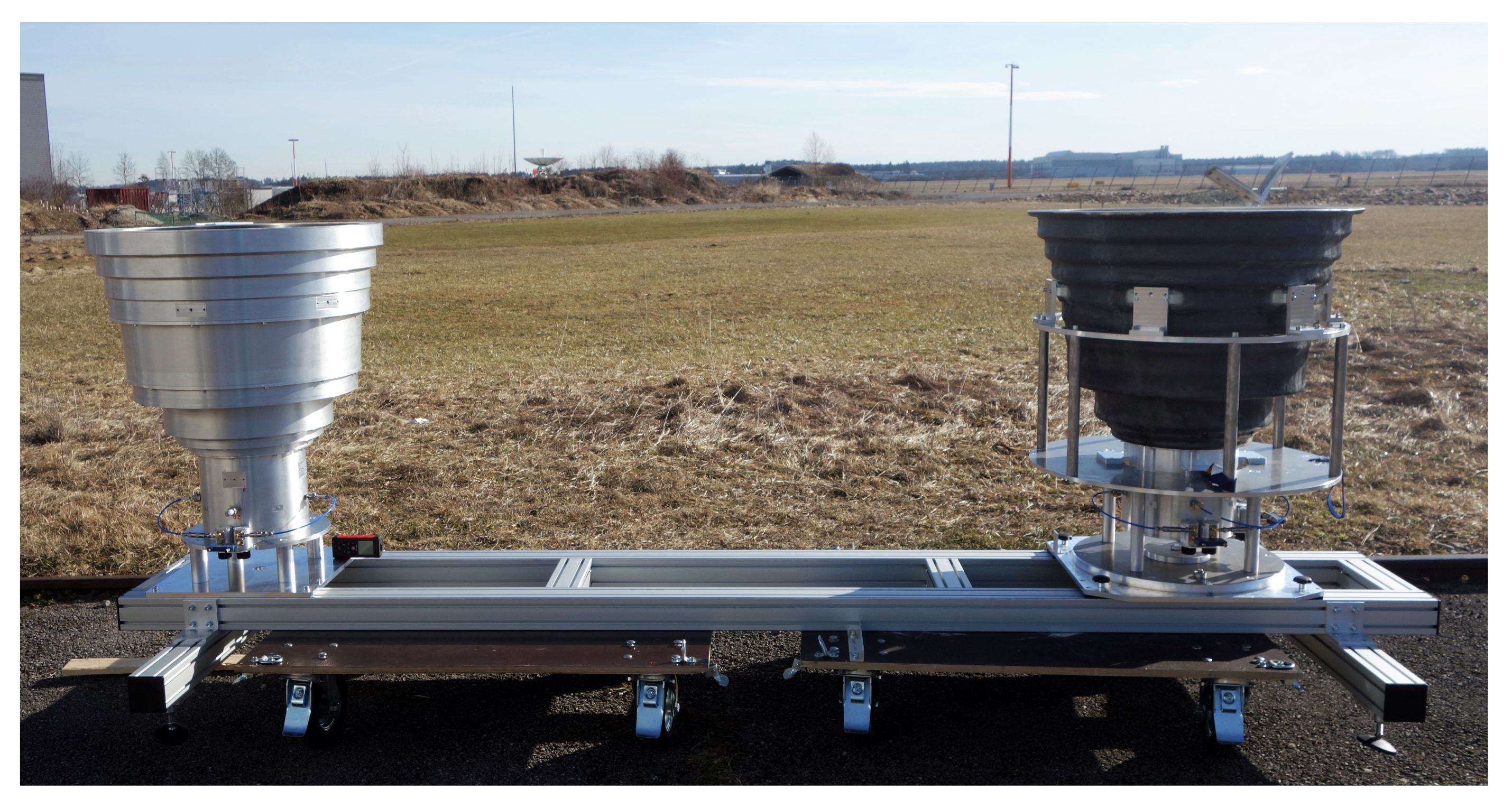
Based on the simulation results a coupling measurement setup was derived to verify the results and to obtain more information regarding the frequency dependence of the parameters. The setup is shown in
Figure 7 and initially utilized an aluminum and a CFK antenna. The antennas were proven to show the same radiation characteristics through far-field measurements in DLR’s CTR and, therefore, could be used as equivalents for the first investigations.
The setup allowed for a variable distance between the antennas and a measurement over a frequency range of with could be conducted using a vector network analyzer (VNA). This frequency range was chosen to include frequency ranges of possible future SAR missions like ROSE-L.
As indicated by the simulation in
Figure 6, the measurements show that the cross-coupling magnitude is about 30 dB lower than the co-coupling magnitude. The further the antennas are placed apart, the better is their decoupling and, therefore, the overall trends shown by the simulation could also be verified. With the cross-coupling mean magnitude at roughly
dB their measured values show high variation and the decreasing trend cannot be observed clearly due to the noise level of the measurement. Nevertheless, both S
and S
are well below the targeted decoupling magnitude and their behavior is therefore uncritical to the fulfillment of said requirement.
Additionally, it can be seen that the co-coupling parameter S is below the target magnitude as well. This means, the determining parameter for the fulfillment of the decoupling requirement is S, as predicted by the simulations.
The difference in magnitude of both co-coupling parameters can be explained by evaluating the simulated near-field of the antennas. When the antenna is excited with a horizontal polarization it generates a greater near-field radiation towards the second antenna than it does while transmitting with a vertical polarization. Therefore, the horizontal polarization of the transmitting antenna is able to couple more into the receiving antenna than the transmitted vertical polarization.
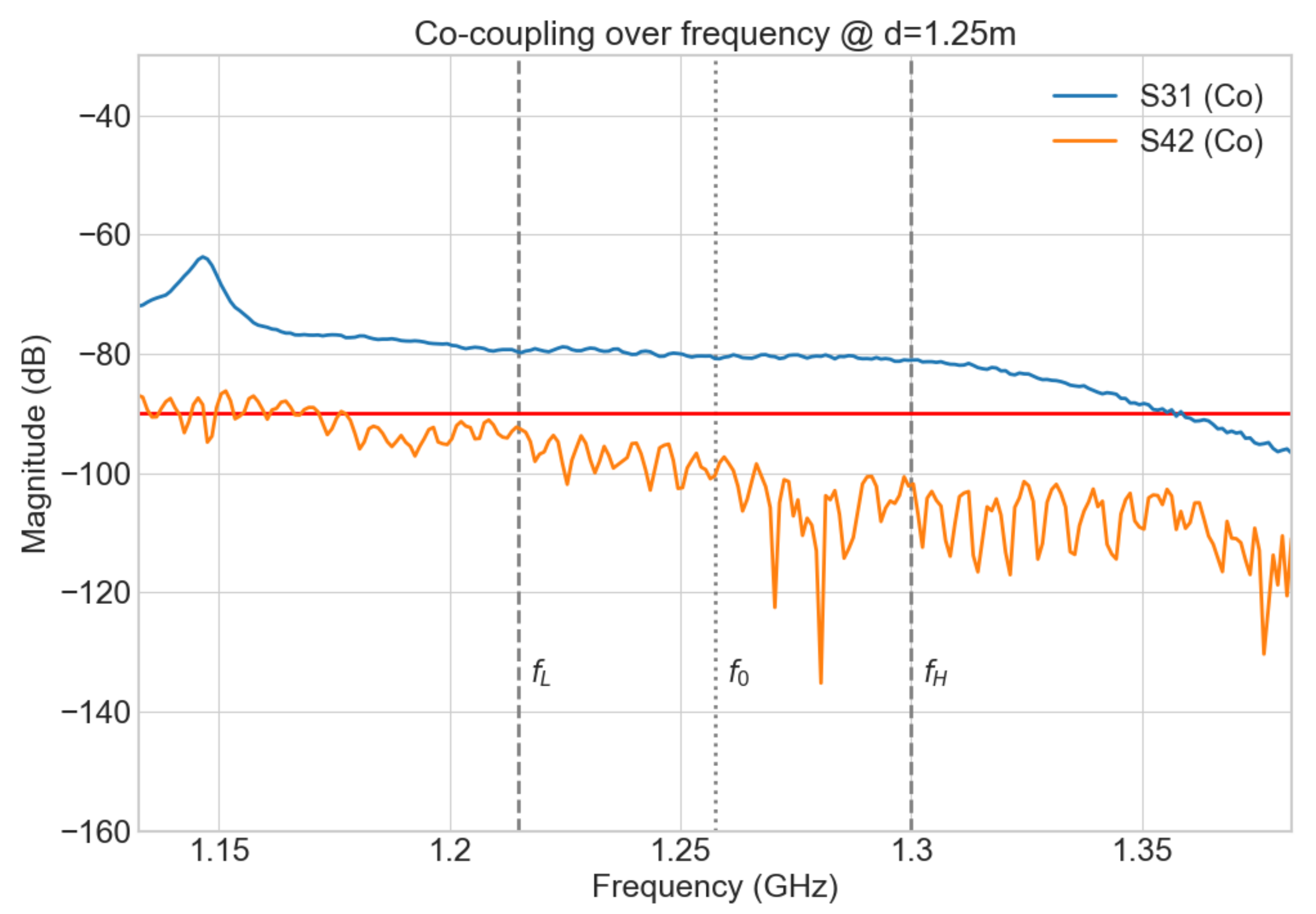
Exemplary, the behavior of the co-coupling parameters over the frequency are shown in
Figure 8 for the distance
. The relevant frequency range for ROSE-L (
) as well as
are annotated in the graph.
It can be seen that S remains below dB over the relevant frequency range, while parameter S is near constant over said range and has a magnitude of dB. As noted previously, the target decoupling magnitude is 90 dB and the described setup did not fulfill the requirement for any of the measured distances. Therefore, additional measures to increase the decoupling of the antennas were investigated and implemented.
5. Improvements and Final Results
In order to further suppress the coupling of both antennas, a choke ring design was developed which is mounted to the antennas’ apertures. This design consists of a base plate onto which vertical rings are attached. The choke rings add around
of height to the antennas and increase the diameter of the antenna to 1
. The vertical rings are equally spaced on the base plate in intervals of
. Their height and distance to each other are related to the chosen frequency
, so that waves traveling along the choke ring’s surface are able to cancel out immediate waves traveling above the ring in close proximity [
7]. Choke rings are widely used to mitigate multipath effects in GPS antennas, which can occur due to reflections from the ground or surrounding objects [
8]. With regard to the coupling setup this effect is exploited to lessen the propagation of waves from the transmitting in the direction of the receiving antenna.
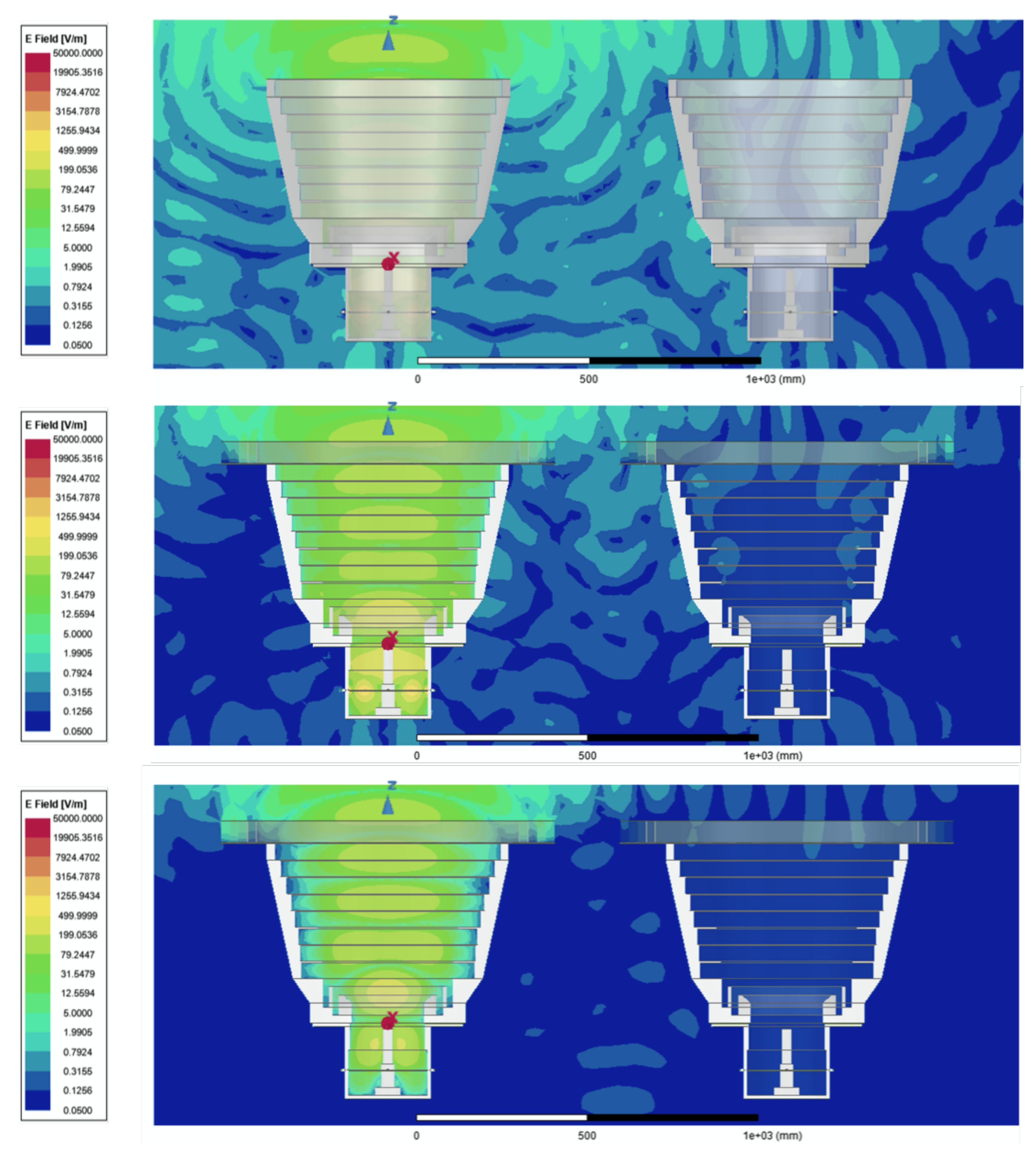
As can be seen in the simulation results of the antennas’ near-field at
in
Figure 9 obtained with the Ansys HFSS simulation software, the electric field density below the antennas’ aperture can be reduced for both polarizations of the VEGA antenna by introducing choke rings. It can also be observed that the excitement of a horizontal polarization (middle) leads to a higher radiation towards the receiving antenna on the right than transmitting with a vertical polarization (bottom).
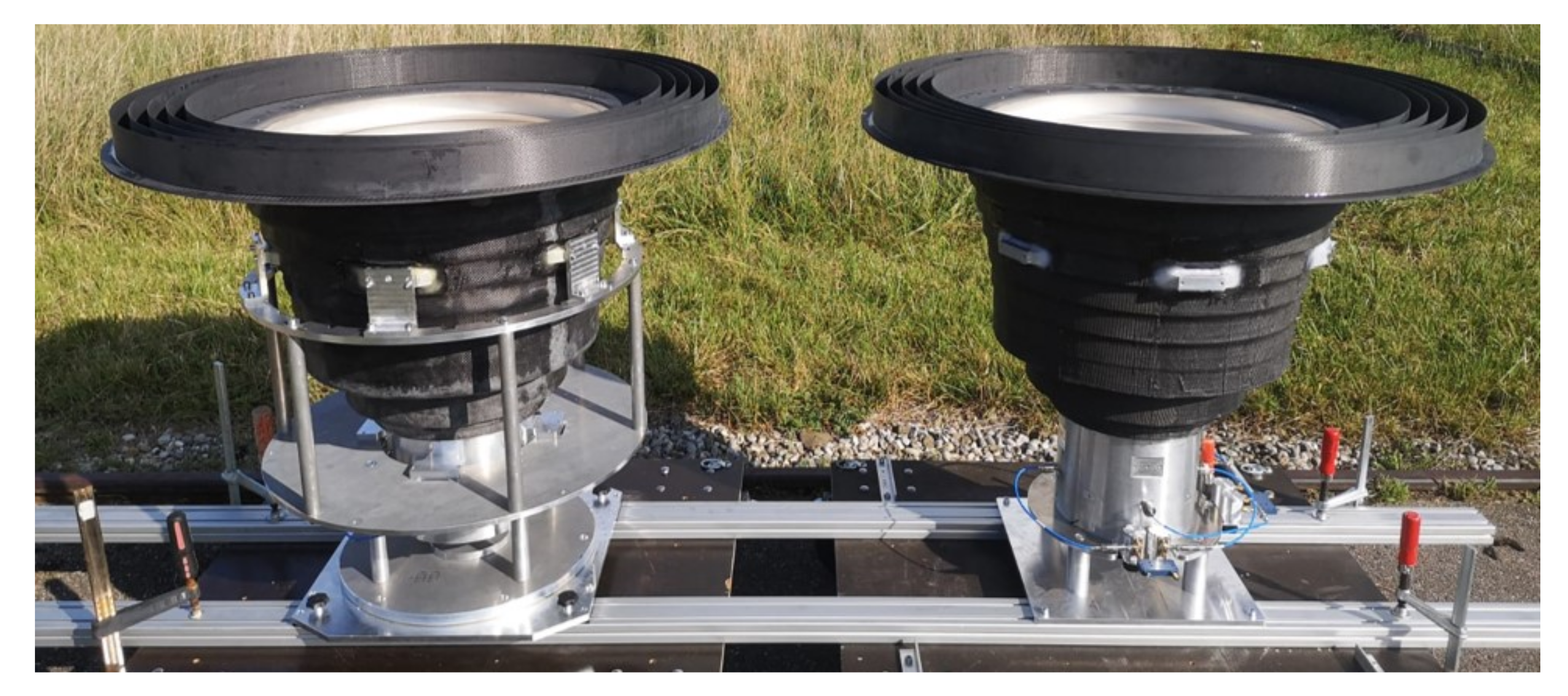
The preliminary testing of the choke rings’ effectiveness was conducted with choke rings made out of aluminum. Due to the thin aluminum rings, the manufacturing process posed various difficulties, such as warping of the material and inaccuracies of the ring positions. Nevertheless, it could be shown that the co- as well as the cross-coupling of the VEGA antennas can be reduced by the use of these choke rings. To decrease weight and to increase the accuracy of the manufacturing process, another pair of choke rings was constructed out of CFK and tested with the setup shown in
Figure 4.
In comparison, the performance of the CFK choke rings was nearly identical to the aluminum choke rings’ performance. With their benefits and ability to realize a significant decrease of the antennas’ coupling the CFK choke rings were chosen for the subsequent measurements.
As in the previous measurements, the cross-coupling magnitude is again well below
dB over the relevant frequency range.
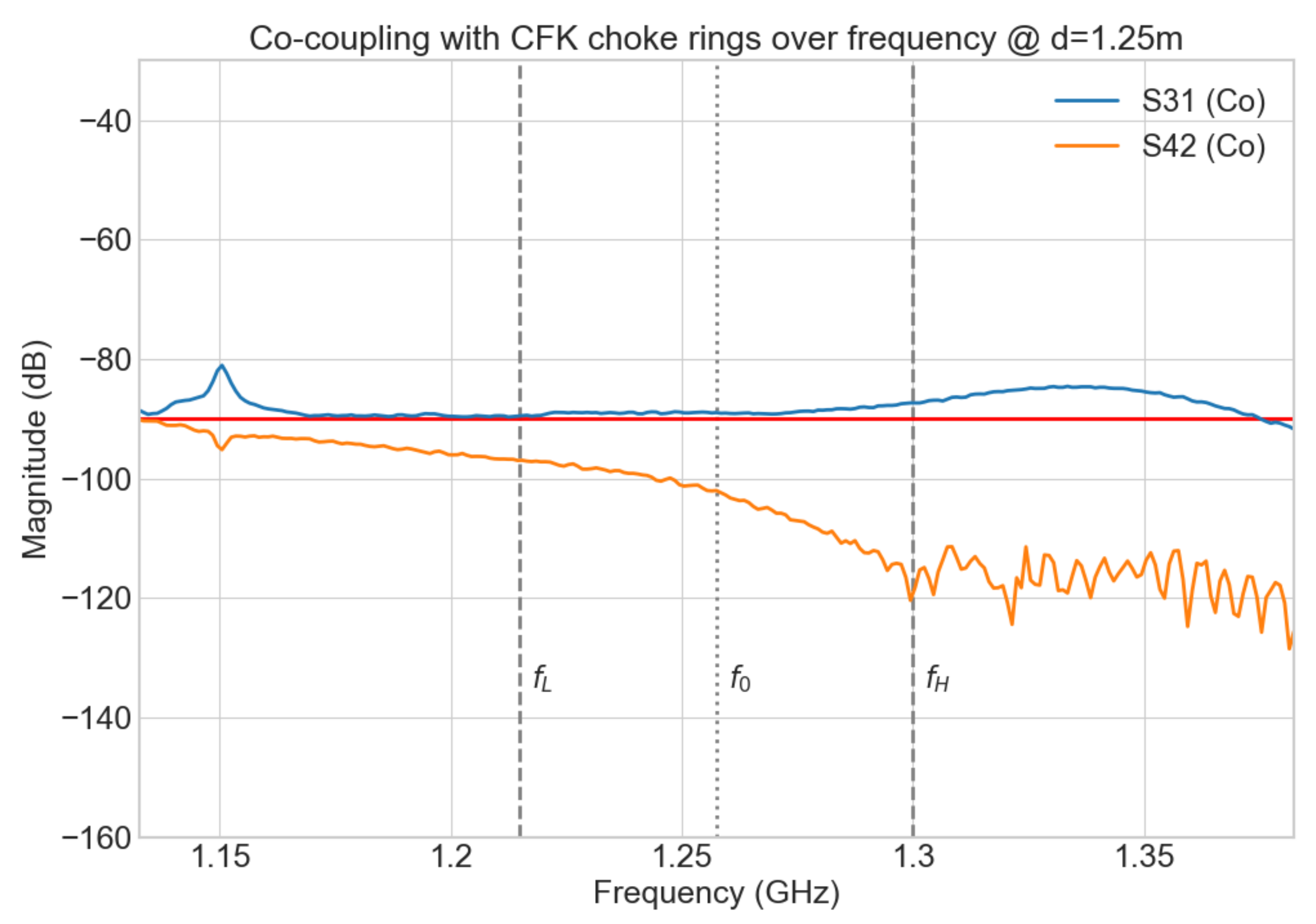
Figure 10 shows the co-coupling results of a frequency sweep with a distance of
between the antennas and a reduction of up to 10 dB can be seen for both co-coupling parameters.
is below the targeted magnitude at all times and reaches a minimum magnitude of approximately
dB. The most relevant coupling parameter,
, is near constant to
dB for the lower frequency range and has a maximum of
dB at
. As can be seen in
Figure 8, the maximum co-coupling magnitude of
is at
dB in the lower frequency range and
dB at
when no choke rings are utilized.
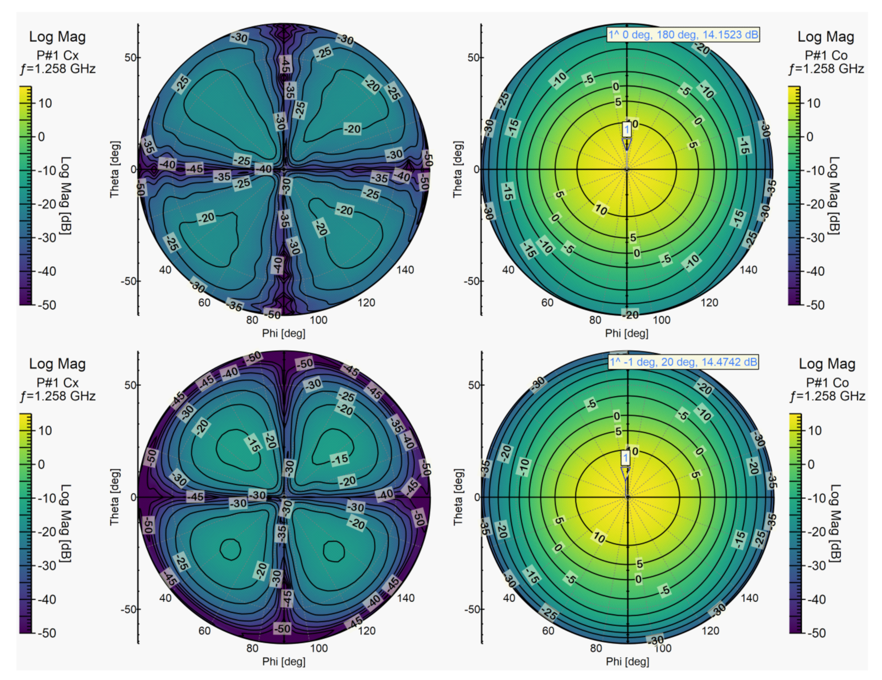
In addition to these measurements the radiation pattern of the VEGA antenna with choke rings was investigated in the CTR. When compared with previous measurements without choke rings, no significant changes could be observed in the main beam characteristics of the antenna.
Figure 11 shows the far-field of the VEGA antenna split into its co- and cross-polarization part, without choke rings on the top and with choke rings on the bottom. The shamrock shape of the antenna’s cross-polarization remains distinctly visible and the co-polarization pattern retains its shape as well. The maximum gain of the antenna changes slightly from
dB to
dB with the use of the choke rings as less energy is emitted in the form of side lobes, and is instead diverted towards the antenna’s main lobe.
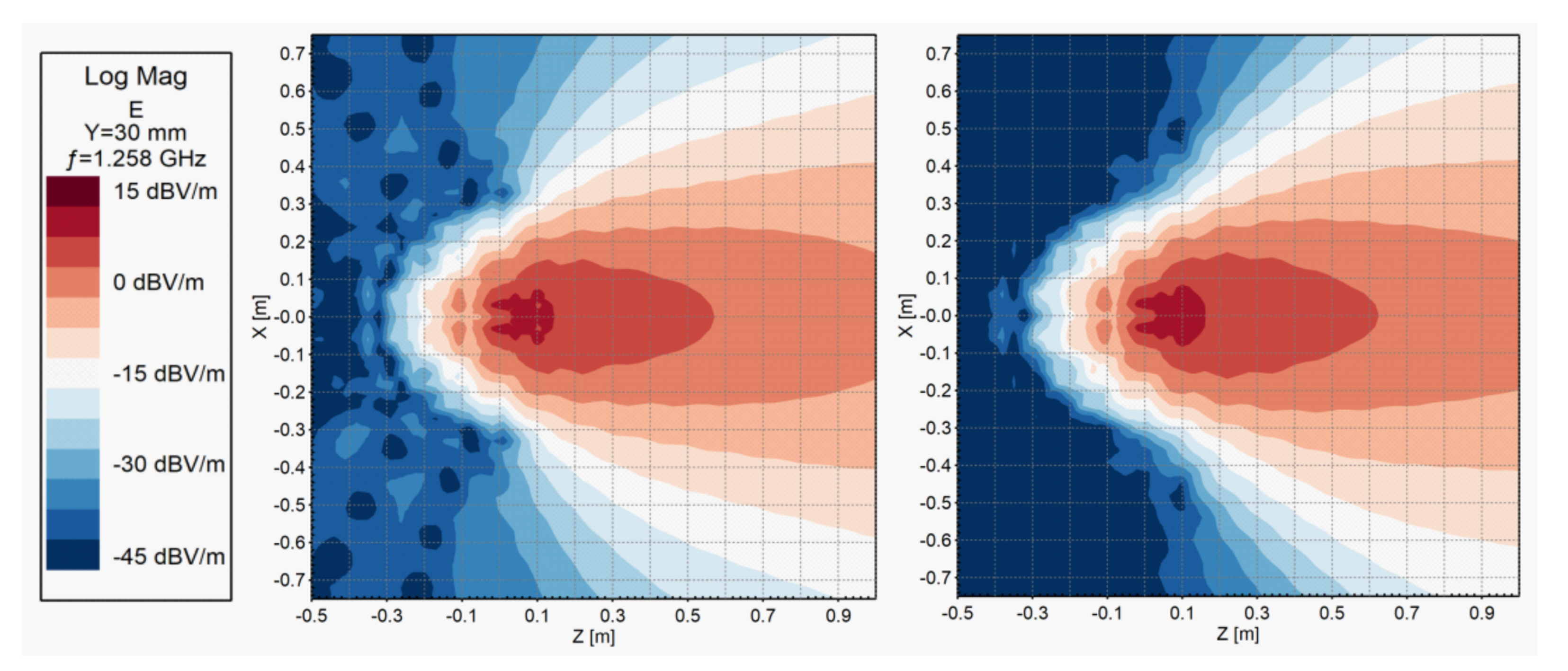
In addition to the far-field pattern of the antenna, the changes in its near-field radiation were investigated and are shown in
Figure 12.
For both views in
Figure 12, the center of the antenna aperture is located on the XY-plane at
. In consequence, the near-field radiation for
is considered a major contributor to the antenna coupling and was significantly reduced through the use of the choke ring. Furthermore, the data derived from the measurement confirms the simulation results shown in
Section 5 in
Figure 9.
With the CTR measurement results, the use of choke rings is accepted as an effective way to reduce the coupling of two VEGA antennas without altering their individual performance.
6. Conclusions
This paper describes and shows the latest steps in the antenna development for DLR’s novel L-band transponders. Comprehensive simulation studies and measurements were conducted to investigate the mutual coupling of dual polarized antennas operated in close proximity.
It could be shown that the combination of the lightweight VEGA antenna with CFK choke rings makes it possible to reach the targeted 90 dB decoupling starting from a distance of between the antenna centers. Based on these results the design of a compact weatherproof outdoor housing as well as the electronics could be finalized and the realization of a compact transponder even in L-band becomes achievable.
Author Contributions
Conceptualization, K.W., M.S. and A.M.B.; methodology, A.M.B.; validation, A.M.B.; investigation, A.M.B., K.W., B.G. and M.L.; data curation, A.M.B.; writing—original draft preparation, A.M.B.; writing—review and editing, K.W. and M.S.; visualization, A.M.B., B.G. and M.L. All authors have read and agreed to the published version of the manuscript.
Funding
This research received no external funding.
Institutional Review Board Statement
Not applicable.
Informed Consent Statement
Not applicable.
Data Availability Statement
Not applicable.
Acknowledgments
The authors thank the staff of the institute’s mechanical lab for their support and expertise during the antenna manufacturing and construction, as well as for their help with the building of the measurement setup.
Conflicts of Interest
The authors declare no conflict of interest.
References
- Moreira, A.; Prats-Iraola, P.; Younis, M.; Krieger, G.; Hajnsek, I.; Papathanassiou, K. A Tutorial on Synthetic Aperture Radar. IEEE Geosci. Remote. Sens. Mag. 2013, 1, 6–43. [Google Scholar] [CrossRef] [Green Version]
- Raab, S.; Rudolf, D.; Weidenhaupt, K.F.; Schwerdt, M. Development of DLR’s Innovative Remote Controlled Calibration Targets-Potential of Polarization Sensitive Measurements. In Proceedings of the European Conference on Synthetic Aperture Radar (EUSAR), Eurogress Aachen, Aachen, Germany, 4–7 June 2018. [Google Scholar]
- Weidenhaupt, K.F.; Raab, S.; Rudolf, D.; Schwerdt, M. Innovative Antenna Concepts for DLR’s Fully Polarimetric Low-Frequency Transponders. In Proceedings of the European Conference on Synthetic Aperture Radar (EUSAR), Eurogress Aachen, Aachen, Germany, 4–7 June 2018. [Google Scholar]
- Gonzalo, R.; Teniente, J.; del Rio, C. Improved Radiation Pattern Performance of Gaussian Profiled Horn Antennas. IEEE Trans. Antennas Propag. 2002, 50, 1505–1513. [Google Scholar] [CrossRef]
- Büchner, A.M. Measurement and Simulation of Mutual Coupling Effects between Dual-Polarized L-Band Horn Antennas for Satellite-Based Radar System Calibration. Master’s Thesis, University of Applied Sciences Jena, Jena, Germany, 2019. [Google Scholar]
- Rudolf, D.; Döring, B.; Jirousek, M.; Reimann, J.; Schwerdt, M. A Compact Antenna Rotation Concept for Precise Polarimetric SAR Calibration Transponders. In Proceedings of the European Conference on Synthetic Aperture Radar (EUSAR), Hamburg, Germany, 6–9 June 2016. [Google Scholar]
- Javad Navigation Systems. Choke Ring Theory. Available online: http://www.javad.com/jns/index.html?/jns/technology/Choke%20Ring%20Theory.html (accessed on 1 September 2021).
- Scire-Scappuzzo, F.; Makarov, S.N. A Low-Multipath Wideband GPS Antenna With Cutoff or Non-Cutoff Corrugated Ground Plane. IEEE Trans. Antennas Propag. 2009, 57, 33–46. [Google Scholar] [CrossRef]
Figure 1.
One of DLR’s remote controlled C-band Kalibri transponders on its two axis positioner. The positioner allows for precise alignment of the transponder in both azimuth and elevation.
Figure 1.
One of DLR’s remote controlled C-band Kalibri transponders on its two axis positioner. The positioner allows for precise alignment of the transponder in both azimuth and elevation.
Figure 2.
Cut through the developed VEGA antenna showcasing its three sections. Together the antenna flare, throat section and planar orthomode transducer (OMT) are able to produce two distinct orthogonal linear polarizations.
Figure 2.
Cut through the developed VEGA antenna showcasing its three sections. Together the antenna flare, throat section and planar orthomode transducer (OMT) are able to produce two distinct orthogonal linear polarizations.
Figure 3.
Lightweight carbon-reinforced-polymer (CFK) VEGA antenna mounted on the positioner of the DLR’s compact test range (CTR). During various measurement campaigns, the antenna pattern of the VEGA antenna on its own, as well as with additional modifications, was determined.
Figure 3.
Lightweight carbon-reinforced-polymer (CFK) VEGA antenna mounted on the positioner of the DLR’s compact test range (CTR). During various measurement campaigns, the antenna pattern of the VEGA antenna on its own, as well as with additional modifications, was determined.
Figure 4.
Outdoors coupling measurement setup with two CFK VEGA antennas and CFK choke rings. Shown in the figure is the mechanical setup without the VNA, which was used to measure all coupling parameters. The distance between the antennas was varied to evaluate the choke rings’ effectiveness in relation to distance and frequency.
Figure 5.
Representation of the antenna coupling setup. Shown on the bottom is a cut through both antennas with their feed-network (FN) setup. The top down view into the antennas shows the resulting polarization when exciting the antenna using the respective feed-network. The antenna on the left is referred to as the transmitting antenna, while the right antenna is consequently set as the receiving antenna.
Figure 6.
Simulation and measurement results for selected co- and cross-coupling parameters. Both simulated and measured data sets show the antenna coupling in dB at a chosen frequency of for various distances between the antenna centers. The target decoupling of 90 dB is marked in red.
Figure 6.
Simulation and measurement results for selected co- and cross-coupling parameters. Both simulated and measured data sets show the antenna coupling in dB at a chosen frequency of for various distances between the antenna centers. The target decoupling of 90 dB is marked in red.
Figure 7.
Outdoors coupling measurement setup. For the measurement one aluminum (left) and one CFK VEGA antenna (right) with equal radiation characteristics were used. Not shown in the picture is the vector network analyzer (VNA) used to measure all coupling parameters at different distances between the antennas.
Figure 8.
Measurement results for both co-coupling parameters S and S in dB at a distance of between the antenna centers plotted against frequency. The relevant frequency range for the ROSE-L mission as well as the decoupling target are indicated in the diagram.
Figure 8.
Measurement results for both co-coupling parameters S and S in dB at a distance of between the antenna centers plotted against frequency. The relevant frequency range for the ROSE-L mission as well as the decoupling target are indicated in the diagram.
Figure 9.
Simulation results obtained with the Ansys HFSS simulation software for the electrical near-field of two VEGA antennas without choke rings (horizontal polarization) (top) and with choke rings for horizontal (middle) and vertical polarization (bottom) of the transmitting antenna. The simulation was conducted using the finite element–boundary integral (FEBI) method, which is a reflectionless boundary condition and requires no theoretical minimum distance from the radiator. With this approach, the simulation volume, which is shown above, could be reduced without influencing the radiation results.
Figure 10.
Measurement results for both co-coupling parameters S and S in dB plotted against frequency while using choke rings on both antennas. The distance between the antenna centers was set at . As before, the relevant frequency range for the ROSE-L mission as well as the decoupling target are indicated in the diagram.
Figure 11.
Measurement results for the horizontal polarization of one VEGA antenna without (top) and with choke rings (bottom) obtained through measurements in DLR’s CTR. The graphs show polar plots of the antenna’s far field split into the co-polarization (right) and cross-polarization (left) for both cases at the chosen frequency .
Figure 12.
Cut through the electrical near-field at for the horizontal polarization of one VEGA antenna without (left) and with choke rings (right) derived from far-field measurements in DLR’s CTR. The radiation propagates along Z and the center of the antenna’s aperture is located at .
Figure 12.
Cut through the electrical near-field at for the horizontal polarization of one VEGA antenna without (left) and with choke rings (right) derived from far-field measurements in DLR’s CTR. The radiation propagates along Z and the center of the antenna’s aperture is located at .
Table 1.
Coupling parameters and corresponding description based on possible polarization sets.
Table 1.
Coupling parameters and corresponding description based on possible polarization sets.
| Polarization Set | Corresponding | Referred to as |
|---|
| (RX, TX) | Parameter | |
|---|
| HH | S | Co-coupling |
| HV | S | Cross-coupling |
| VH | S | Cross-coupling |
| VV | S | Co-coupling |
| Publisher’s Note: MDPI stays neutral with regard to jurisdictional claims in published maps and institutional affiliations. |
© 2021 by the authors. Licensee MDPI, Basel, Switzerland. This article is an open access article distributed under the terms and conditions of the Creative Commons Attribution (CC BY) license (https://creativecommons.org/licenses/by/4.0/).


