Article

Sentinel-1 Data Processing for Detecting and Monitoring of Ground Instabilities in the Rocky Coast of Central Asturias (N Spain)

by
José Cuervas-Mons
1,*,
María José Domínguez-Cuesta
1,
Félix Mateos Redondo
2,
Anna Barra
3,
Oriol Monserrat
3,
Pablo Valenzuela
4 and
Montserrat Jiménez-Sánchez
1
1
Department of Geology, University of Oviedo, 33005 Oviedo, Spain
2
GEA Asesoría Geológica—S. COOP ASTUR, 33192 Llanera, Spain
3
Geomatics Division, CTTC/CERCA, 08860 Castelldefels, Spain
4
Tecnologías y Servicios Agrarios, Tragsatec S.A., 24008 León, Spain
*
Author to whom correspondence should be addressed.
Remote Sens. 2021, 13(16), 3076; https://doi.org/10.3390/rs13163076
Submission received: 28 June 2021 / Revised: 29 July 2021 / Accepted: 31 July 2021 / Published: 5 August 2021
(This article belongs to the Special Issue Advances in Remote Sensing in Coastal Geomorphology)

Abstract

:
The cliff coastline of the central region of Asturias (N Spain) is severely affected by terrain instabilities, causing considerable damage to properties and infrastructures every year. In this study, we applied the A-DInSAR technique based on Sentinel-1 imagery to map and monitor active slopes in an emblematic rocky area of the Asturian coast: the Peñas Cape. The A-DInSAR dataset analysis has been focused at regional and local scales. For the local scale assessment, six areas were selected based on previous work and the landslide database of the Principality of Asturias region (BAPA-Base de datos de Argayos del Principado de Asturias), created by the University of Oviedo. The processing of the data has been performed using two independent sets of processing tools: the PSIG software tools, a professional tool and, the GEP service, an unsupervised platform. The dataset consisted of 113 SAR IW-SLC images acquired by the Sentinel-1 A/B satellites between January 2018 and February 2020. LOS mean deformation velocity maps (mm year−1) and deformation time series (mm) were obtained by PSIG and GEP software, allowing coastal areas with landslide incidence and other terrain movements to be distinguished. Deformation motion has been estimated from PSIG VLOS rates to be from −17.1 to 37.4 mm year−1 and GEP VLOS rates from −23.0–38.3 mm year−1. According to deformation time series (mm), the minimum and maximum accumulated displacements are −68.5–78.8 and −48.8–77.0 mm by means of PSIG and GEP, respectively. These ground motions could be associated with coastal instabilities related to marine activity and coastal retreat, both at regional and local study scales. The main contributions of this work are: (1) the demonstration of the potential of A-DInSAR techniques to evaluate coastal instabilities in a coastal retreat context and (2) the comparison of the results provided by the two sets of tools, which allowed the ground motion to be assessed by using an unsupervised approach vs. a contrasted one (robust software). This study increases the knowledge about coastal instabilities and other ground movements along the rocky coast and cliffs of Central Asturias. As a conclusion for the future, we believe that this work highlights the evaluated methods as significant tools to support the management of coastal territories with jagged and rocky coastlines.

1. Introduction

1.1. Background

Satellite based A-DInSAR (Advanced-Differential Interferometry Synthetic Aperture Radar) techniques have been used since the end of the last century as powerful tools to detect, monitor, and analyze natural hazards. These methods combine the information obtained from a set of satellite SAR interferograms to retrieve deformation time-series, ground displacement velocities, topographic information, atmospheric artifacts, and orbital errors [1]. Among them, Persistent Scatter Interferometry (PSI) [2,3] and Small Baseline Subsets (SBAS) [4] are the most representative ones. The authors of [5] provide a comprehensive review of such methods. The range of applications is wide, including seismic and volcanic risk [6,7,8], subsidence phenomena [9,10,11,12], landslide activity [13,14,15,16], overexploitation of aquifers [17,18,19], and civil infrastructure monitoring [20,21,22]. One of the key factors of these techniques is the great satellite data availability acquired by different satellite constellations providing different performances: (1) C-Band Satellites (ERS-1/2, Envisat ASAR, Radarsat, and Sentinel-1) with a wavelength around 5.5 cm, (2) L-Band (ALOS PALSAR) with a wavelength around 23 cm, and (3) X-Band (TerraSAR-X, COSMO-SkyMed and PAZ), with a wavelength around 3.1 cm. These constellations will be complemented in the near future with the new generation of high-resolution satellites such as Capella Space (REFE) or Ice Eye (REFE). They will be able to provide 30–40 cm resolution images every few hours.
In this paper, we have used images acquired by the C-Band ESA constellation Sentinel-1, which provides a unique performance acquired over the whole Earth every 6 days. This represents a significant improvement with respect to previous C-Band satellites, considerably increasing the monitoring potential of geohazards over large areas [23]. Moreover, the medium size wavelength (5.6 cm) and the relatively high resolution (≈4 × 14 m) provide a good trade-off to map ground displacement over the bare surface and sparse vegetation [24], which are the most common types of surface in our area of interest.
Rocky coasts represent about 75–80% of coasts worldwide [25]. In recent decades, several authors [26,27,28,29] have addressed their studies of these coasts from a geomorphological and evolutionary point of view. Some of them [30,31,32,33] have focused on the development of slope instabilities and the measurement of cliff retreat rates. Others [14,34,35,36] have applied different A-DInSAR techniques to monitor terrain deformation by means of InSAR data. In coastal areas, the SAR dataset provided by Sentinel-1 A/B is used to define the coastline [37], to detect landslide activity [23,38,39], and to analyze ground displacements and subsidence phenomena [40,41,42].
The cliff coast of Asturias has already been studied by [43,44,45], focusing mainly on the development of slope instabilities that causes coastal retreat. These studies have included photointerpretation analysis, the use of unmanned airborne vehicles (UAV), and field work topographic campaigns since June 2018, continuing to date.
The present work is based on the use of A-DInSAR techniques to detect and monitor coastal instabilities over a regional sector of the central Asturian coast (N Spain) (Figure 1), with the main goal of analyzing their relationship with coastal retreat. For this purpose, different local areas with known landslides and other ground movements have been chosen for study, considering previous data recorded in the BAPA (Base de datos de Argayos del Principado de Asturias-Principality of Asturias Landslide Database [46].
Considering that A-DInSAR techniques are only capable of detecting very slow movements (<1.6 m year−1) [47], the scope of this work aims to assess the potential and limitations presented by the A-DInSAR techniques for mapping and monitoring of ground movements in cliff coastal areas. For this purpose, we used Sentinel-1 data and two different approaches: a robust and supervised approach and an unsupervised and automatic approach. In this way, the combined use of both software methodologies is due to the necessity: (i) to avoid unmonitored areas, increasing the number of PS (velocity points) detected, and (ii) to provide and improve the interpretation of the A-DInSAR dataset. In addition, and as a novelty of this study, we demonstrate the high capability and utility of the unsupervised service to detect and monitor ground movements at a local scale.

1.2. Setting of the Study Area

The study area is located in the coastal region of Peñas Cape environment, on the central coast of Asturias (N Spain) (Figure 1). The area encompasses 187 km2 and includes, from West to East, the administrative areas of Castrillón, Avilés, Gozón, Carreño, and Gijón, whose total population is 393,364 inhabitants [48]. This area is characterized by the presence of the urban areas of Avilés and Gijón, with important economic and industrial activity and important Port infrastructures [49]. Additionally, there are smaller towns such as Salinas, Luanco, and Candás, whose principal economic activities are tourism and fishing. The study area has a characteristic Oceanic climate, with average values of annual precipitation and temperature of 1122 mm year−1 and 13.2 °C (Avilés-Airport weather station) [50]. From a geographical and geomorphological point of view, the study area is characterized by a coastline pattern with inlets and promontories, with small beaches (only one more than 1.5 km long) and cliffs with slopes of above 65° and heights close to or greater than 100 m [44]. The predominant relief along the coast is the “rasa” [51,52], which defines a characteristic W-E direction plain relief with altitudes ranging from over 60 to 80 m.a.s.l., and formed by alluvial, peat, slope, and beach deposits, with ages from Pliocene to Holocene [52]. In addition, the estuary of Avilés, situated in the West of the area, is another important geomorphological element [44]. Geomorphological activity is mainly associated with coastal and gravity processes and, locally, with karst development [44].
From a geological point of view, the study area is mainly located in the Cantabrian Zone and the Permian-Mesozoic-Paleogene cover of the Cantabrian Mountains [53]. The bedrock mainly consists of an almost complete Paleozoic succession with the exception of the Cambrian, which is absent. According to [54,55], the Lower Paleozoic is predominantly constituted by siliciclastic rocks (quartzsandstone, shale, and sandstone), having an Ordovician volcanic level (volcanodetritic materials, basalts, and cinerites). The Upper Paleozoic is formed by alternations of carbonate and siliciclastic sections (dolomite, limestone, marl, sandstone, slate, shale, and quartzsandite). The Permo-Triassic and Mesozoic materials are discordantly arranged in this Paleozoic basement [55] and separated by faults with little displacement. These units are constituted by siliciclastic and carbonate materials such as slate, sandstone, conglomerate, limestone, dolomite, and gypsum. The most recent materials are quaternary in age and are composed of alluvial, beach, estuary, and colluvial sediments, defining different geoforms, among which the rasa stands out.

2. Materials and Methods

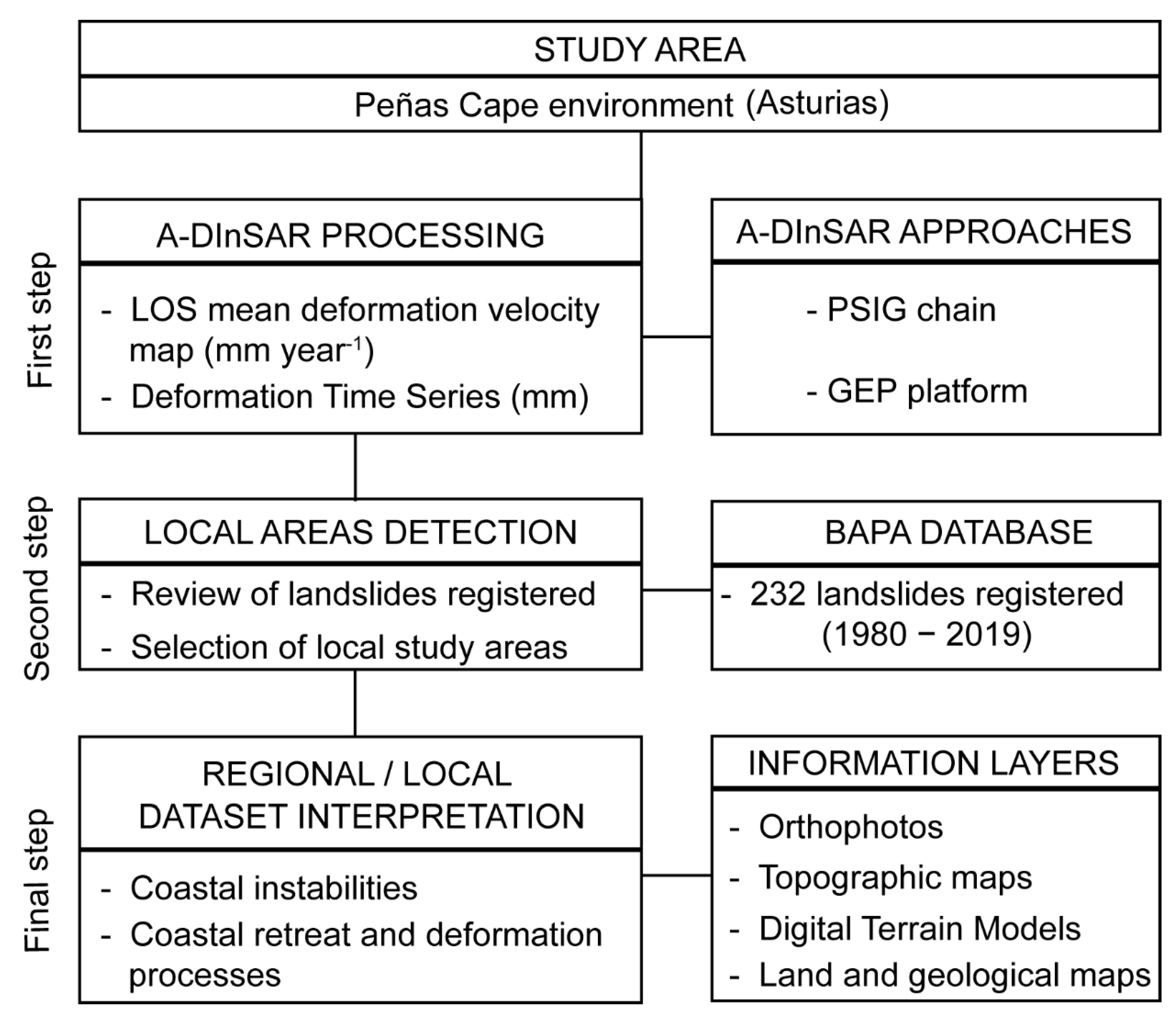
This section describes the procedure followed in this work (Figure 2). Firstly, we applied A-DInSAR techniques by exploiting Sentinel-1 A/B images of the study area. Secondly, the BAPA database was used to establish the key local areas. The data provided by A-DInSAR were analyzed, both at regional and local scales, in order to identify and interpret the coastal instabilities and their relationships with coastal retreat.

2.1. A-DInSAR Processing

Available SAR data consisted of 113 IW-SLC SAR images acquired by Sentinel-1A/B satellite in C-Band (5.4 cm wavelength) during the period January 2018–February 2020 and descending orbit (Table 1). For A-DInSAR processing (Figure 2), 2 different approaches have been used: (i) PSIG chain (Persistent Scatterer Interferometry of the Geomatics Division), a robust software developed by CTTC [56,57,58] and (ii) GEP platform (Geohazard Exploitation Platform), an unsupervised service [59,60] with P-SBAS algorithm implemented [1].
The general procedure of A-DInSAR processing consisted of: (i) co-registration of SAR images and generation of wrapped interferograms; (ii) estimation of residual topographic errors and line-of-sight (LOS) mean velocity over a network of PS, according to amplitude and coherence threshold criteria; (iii) interferogram phase unwrapping and assessment of deformation time series; (iv) estimation and filtering of the atmospheric component using a low pass spatial (LPS) filter in PSIG. In GEP, an atmospheric phase screen (APS) filter was included in the algorithm; (v) geocoding and implementation of LOS mean deformation velocity map (mm year−1) and deformation time series (mm) in a Geographical Information System (GIS). The main processing parameters of both approaches are shown in Table 1.
With respect to the processing conducted in this research, the A-DInSAR dataset consisted of large regional processing of the whole of Central Asturias using both approaches. The reference points were located in the city of Oviedo, which was located to the South and outside our study area. The geographical location of the reference points is shown in Table 1. Afterward, in order to focus only on the coastal area, a buffer of 3 km from the coastline was created (Figure 1), and only the PS measured into this study area have been considered.
Concerning measured PS, the sign indicated a movement towards the satellite if the value was positive; the value was negative if the movement was away from the satellite [61]. In this work, since the Sentinel-1 SAR images used were acquired in descending orbit, the highest sensitivity will be obtained when terrain orientations were 278 degrees with respect to N and a slope of 55° approximately.

2.2. Local Areas Detection

At present, the BAPA landslide and ground movements database, developed by the Department of Geology (University of Oviedo, Oviedo, Spain), covers the period 1980–2019, recording 2839 individual landslides. Information was classified in 105 data fields. Data accuracy of the spatial location and temporal occurrence of the landslides were evaluated and validated through field work. Moreover, the inventory included data about the source, the type of landslides, the triggering factor and the damage, costs and affected infrastructures, among others [46].
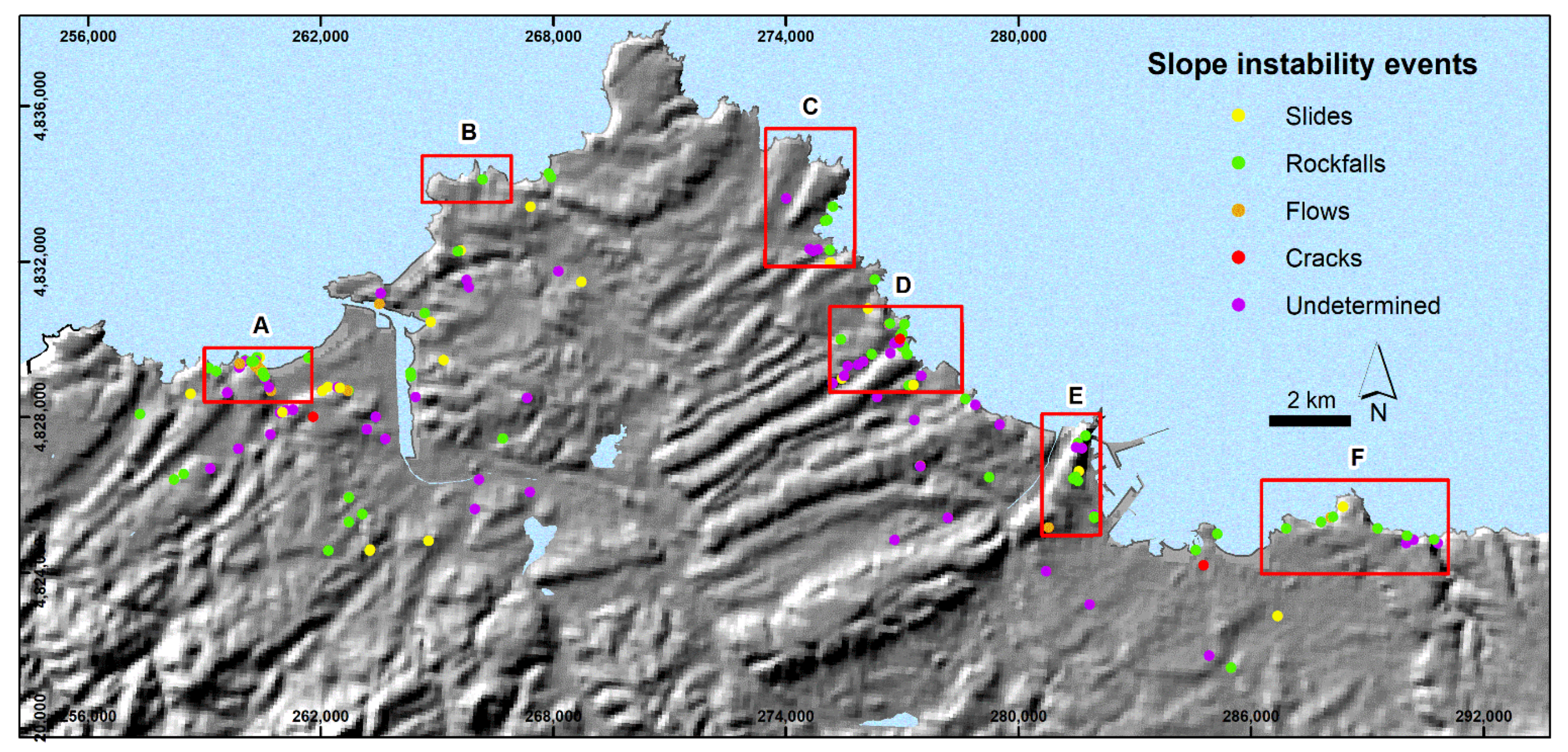
All the inventoried landslides present in the study area have been reviewed (Figure 2). A total of 232 landslide events were registered between 1980 and 2019 in the study area; 37.5% of them were classified as rockfalls, 14.2% as slides, 14.3% as flows, 1.7% were cracks, and 32.3% were undetermined instabilities (Figure 3). Different local areas have been selected in order to apply A-DInSAR techniques according to i) the BAPA database, by considering the spatial distribution of landslides, and ii) previous studies about cliffs on the Asturian coast [43,44,45]. In this way, historical landslides and other known terrain instabilities are taken into account for the interpretation of results. Moreover, new ground deformations associated with mass movements have been detected and studied using remote sensing.
The selected local areas were as follow, from West to East (Figure 3):
  • Salinas Town. With an area of 3.9 km2, it is highly anthropized and urbanized, encompassing the urban centers of Arnao, Salinas, and La Vallina, among others. Its maximum altitude is 85 m, and the coastal orientation is towards the North. There are 72 mass movements recorded in the BAPA database in this sector.
  • Podes Peninsula. With an area of 2.8 km2, it is a predominantly rural area, with very few buildings. Its maximum altitude is 75 m, and the coast orientation is towards the North. Only one mass movement is registered in the BAPA database.
  • Luanco Town. With an area of 8.1 km2, it includes the urban area of Luanco, the rest being predominantly rural. Its maximum altitude is 90 m, and the predominant coastal orientation is towards the East and North. Nine mass movements are recorded in the BAPA database in this sector.
  • Candás Town. With an area of 7.5 km2, it includes the urban area of Candás and other small villages. Its maximum altitude is above 100 m, and the predominant coastal orientation is towards the Northeast. There are 37 mass movements recorded in this sector.
  • Musel Port. With an area of 4.7 km2, it is located to the West of the city of Gijón. It is the most important and critical port infrastructure of Asturias. Its maximum altitude is 120 m, and the predominant coastal orientation is towards the East. Thirteen mass movements are recorded in this sector.
  • Peñarrubia Beach. With an area of 11.6 km2, it is located in the East of the study area and is to the East of the city of Gijón. Its maximum altitude is 100m, and the predominant coastal orientation is towards the North. Twelve mass movements are recorded in this sector.

2.3. Interpretation of Regional and Local Dataset Acquired with A-DInSAR

For an adequate interpretation of the dataset acquired with A-DInSAR, at a local and a regional scale, different information layers have been analyzed together with the geocoded PS in a GIS environment (ArcGIS 10.3). The geo-information layers used are the following (Figure 2):
  • Aerial orthophotos acquired in 2017 (OrtoPNOA 2017 CC-BY 4.0 scne.es) with a pixel resolution of 0.25 m.
  • Topographic maps of the Principality of Asturias at scale 1:25,000.
  • Digital Terrain Models: Elevation, Slope, and Orientation with pixel resolution of 5 × 5 m.
  • Soil and geological maps at 1:25,000 and 1:50.000 scales, respectively.
  • Land use map of 2014 at scale 1:25,000 by SIOSE plan (Sistema de Información de Ocupación del Suelo en España- Land Occupation Information System in Spain).

3. Results

In this section, the obtained A-DInSAR results are shown at regional and local scales. Firstly, we describe PSIG and GEP results at a regional scale. Afterward, different detected deformation sectors were analyzed in detail, and some coastal instabilities were shown. Finally, a detailed analysis of a local area was shown as a representative example (Salinas Town, Figure 3).

3.1. A-DInSAR at Regional Scale

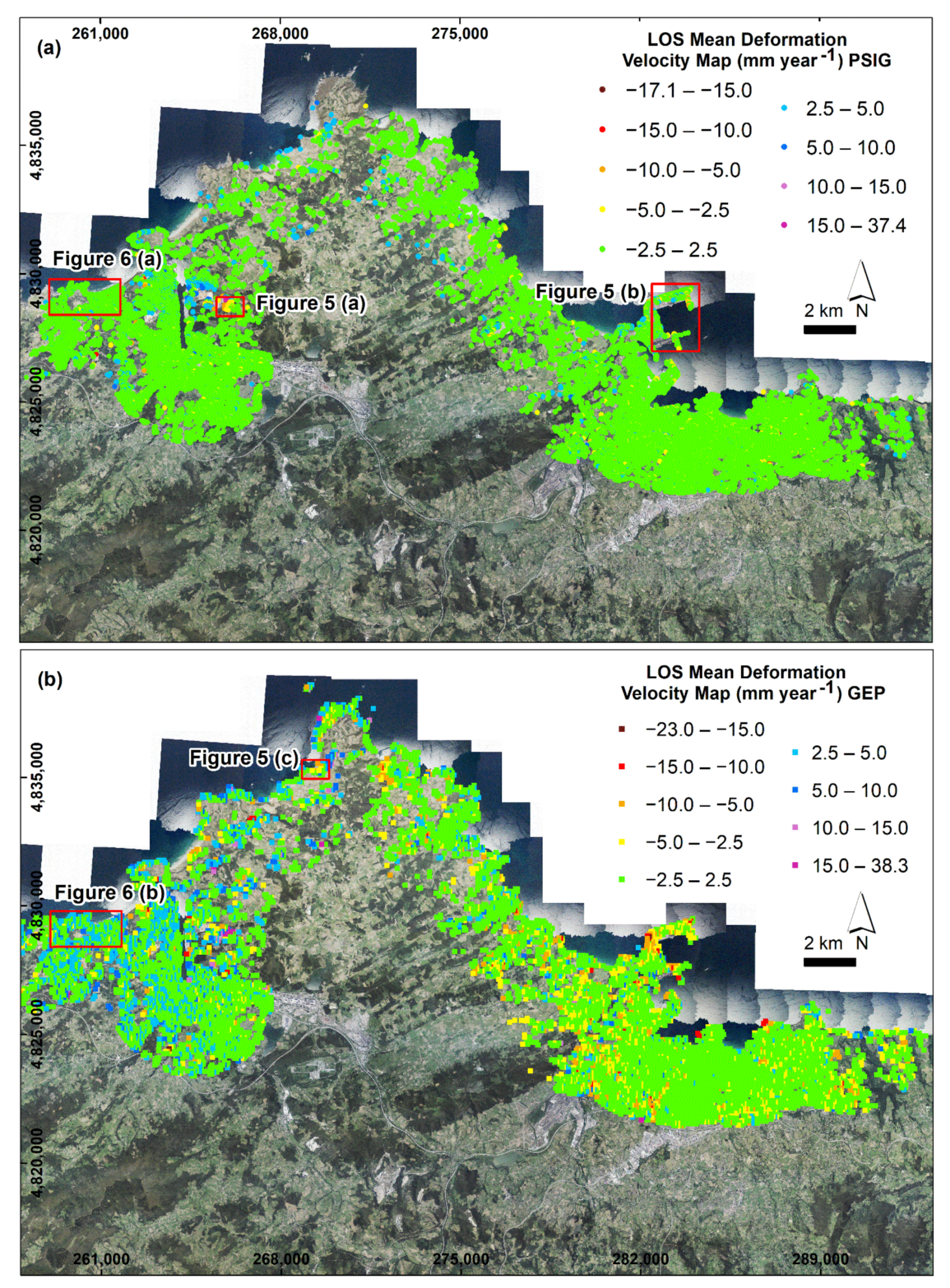
The LOS mean deformation velocity maps (mm year−1) obtained by the PSIG chain and GEP service are presented in Figure 4 and are summarized in Table 2. There was a great difference in the total number of PS detected between the PSIG and GEP maps. A total of 151,722 PS (811.3 PS km−2) were obtained with the PSIG chain. With the GEP service, a total of 16,654 points were measured (89.1 PS km−2). The LOS velocity ranges estimated were similar to each other. In PSIG, the minimum and maximum LOS velocities were −17.1 and 37.4 mm year−1 (mean value is 0.0 ± 1.1 mm year−1). For GEP service, the minimum and maximum LOS velocities were −23.0 and 38.3 mm year−1 (mean value is 0.0 ± 2.6 mm year−1).
In order to compare the ground movement rates, we have considered as active PS those above ± 2.5 mm year−1. This threshold was selected according to the standard deviation of GEP results (σ =±2.6). In the case of PSIG, there were 146,855 PS (96.79%) with LOS mean velocity between -2.5 and 2.5 mm year−1. However, in the GEP results the total number of PS between −2.5 and 2.5 mm year−1 was 16,654 (74.53%). With respect to the accumulated displacement, PSIG detected between −68.5 and 78.8 mm (mean value 0.1 ± 3.6 mm). With GEP, we have measured between −48.8 and 77.0 mm (mean value 1.1 ± 5.1 mm).
Figure 4 makes it possible to distinguish several differences between the results of the approaches. Firstly, GEP presents a wider distribution of dispersed active PS across the whole area, without delimiting deformation areas. Nonetheless, the active PS of PSIG appeared to define ground movement areas. On the other hand, there were some sectors where PSIG had barely detected PS whereas GEP had detected movements: the northernmost zone of Peñas Cape and the Podes sector, for example. In the first case, the LOS velocities detected were between –8.6 and 15.2 mm year−1. The minimum and maximum accumulated displacements were −17.2 and 30.1 mm. In the Podes peninsula, the PS present LOS velocities from −6.8 to 12.9 mm year−1.
Figure 4a shows the LOS mean deformation velocity map (mm year−1) obtained by PSIG. LOS velocity PS < −10.0 mm year−1 (15 PS, 0.01%) were detected, as isolated PS, in Avilés and Gijón cities and Musel Port infrastructures. They cannot be considered as good PS for interpretation. LOS velocity rates between −10.0 and −5.0 mm year−1 (184 PS, 0.12%) and from −5.0 to −2.5 mm year−1 (2049 PS, 1.35%) appear grouped in some areas with significant deformations (Figure 5a,b). The LOS velocity rate of 2.5–5.0 mm year−1 (2,426 PS, 1.60%) are the most difficult to analyze. They can be observed across the study area as grouped and isolated PS. Moreover, they appear on some cliffs whose orientation is predominantly northward. We have related them with abundant unfiltered atmospheric noise. PS with LOS rate of 5.0–10.0 mm year−1 (167 PS, 0.11%) appear in industrial districts and open pit mining. These deformations were produced by anthropic activity (accumulation of materials). There were only 26 PS (0.02%) with LOS mean velocity > 10.0 mm year−1, which were located on an anthropic deposit to the East of Avilés. It could be related to the accumulation of material.
Figure 4b displays the LOS mean deformation velocity map (mm year−1) obtained by GEP. LOS velocity PS < −10.0 mm year−1 (49 PS, 0.29%) was found as isolated PS except at Musel Port, where some interesting ground movements can be observed. LOS velocity rates of −10.0–−5.0 mm year−1 (513 PS, 3.08%) and -5.0 to −2.5 mm year−1 (1295 PS, 7.78%) appeared throughout the study area. These deformations were seen predominantly in the East of the study area (Gijón city and Peñarrubia sector). These PS were difficult to interpret on a regional scale, as they could represent terrain and coastal instabilities (Figure 5c) or an uncorrected atmospheric component. However, there were deformations that may show movements associated to ground coastal instabilities (Figure 5c). LOS rates from 2.5–5.0 mm year−1 (1956 PS, 11.74%) and 5.0–10.0 mm year−1 (385 PS, 2.31%) were observed over the whole of the study area. As in the previous case, detailed local analysis should be conducted to obtain a correct interpretation because a significant influence of artifacts and an atmospheric component could act at a regional scale. Finally, PS with LOS mean velocity > 10.0 mm year−1, of which there were 43 (0.26 %), found as isolated PS and indicating deformation in an open pit in Avilés city; these velocities can be associated with the accumulation of anthropic materials.
Some examples of landslides and coastal instabilities at a regional scale are shown in Figure 5a,b show deformations detected only by means of the PSIG approach, while C displays ground movements measured by the GEP service and PSIG chain.
The case of Figure 5a consists of deformations detected in an electrical sub-station to the East of Avilés city. This area was located over anthropic materials overlying a Jurassic bedrock composed of siliceous conglomerate and sandstone. The deformations present VLOS ranging from −12.4 to 0.6 mm year−1, and an increase in the velocity can be observed from the flat areas to the sloping areas. The deformation time series show a minimum accumulated displacement of −24 mm (Figure 5a). Their trends display a stable period from January to July 2018, there then being a more or less constant period of ground movement until February 2020 (Figure 5a).
Figure 5b shows deformations registered in Musel Port breakwater wall, with VLOS rates from −8.6 to 6.3 mm year−1. It is an example of deformation in coastal infrastructure. The deformation time series registered a minimum and maximum displacement of −35.6 and 34.5 mm. In general, there was an intense episode of deformation during the 4 months from January to April 2018, with accumulated displacements from −5 to −20 mm (Figure 5b). As in April, a deformation trend was observed until February 2020, but slower, even reaching stabilization in some cases. On the other hand, the positive PS presents maximum LOS velocities of 6.3 mm year−1. Their time series have different deformation patterns, with maximum accumulated displacements of 12.5 mm.
Figure 5c shows PS with VLOS from −9.1 to 8.1 mm year−1. The bedrock was composed of shale, sandstone, and volcanoclastic rocks, covered by rasa deposits. At the foot of the cliffs there were beach deposits. Despite the low resolution of the GEP product (90 × 90 m), a possible coastal instability was observed. It presents LOS velocities ranging between −9.1 and −2.5 mm year−1. In addition, the time series has a minimum and maximum displacements of -22.7 and 13.1 mm, with a stable period (January 2018 to July 2019) followed by a period of increasing deformation until February 2020. On the other hand, PSIG has detected LOS velocities between −3.6 and 5.6 mm year−1. The PS measured over buildings make it possible to reliably distinguish the ground motion area detected by GEP. The few positive PS can be considered as noise or as an atmospheric component.

3.2. A-DInSAR at Local Scale

In this section, we present the A-DInSAR dataset (Table 3) obtained in all the selected local areas (Figure 3 and Figure 4). In addition, we show the analysis of one of them, Salinas town, which has been selected due to the significant problems related to slope instabilities registered in the BAPA database.
In general, all the local areas present an adequate PS density for a local analysis. In the case of the PSIG software, the densities were higher than 364.0 PS km−2. The GEP service presents densities higher than 30.4 PS km−2 (Table 3). The density of PS obtained with PSIG was much higher than that of GEP, in the order of 5.7–8.3 times. The exception was found in the Podes Peninsula area, where there was not an adequate density of PS (30.4 PS km−2 of GEP and 8.9 PS km−2 of PSIG) (Table 3).
On the other hand, the deformation velocities observed were different from one area to another. For example, in the case of the Musel Port area, the PSIG software had detected LOS mean deformation velocities of between −17.1 and 6.0 mm year−1, while the GEP service had measured rates from −12.3 to 9.7 mm year−1. Likewise, their deformation time series present minimum and maximum accumulated displacements of −53.6–33.6 and −26.8–32.1 mm, respectively (Table 3).
Of the 6 areas studied at a local scale, the Salinas area was the one that best represents the history of slope instabilities in the Peñas Cape surroundings. This area was situated in the West of the study area, including the town of Salinas (Castrillón administrative area) (Figure 3, Figure 4, Figure 6 and Figure 7). From a lithological point of view, the bedrock was constituted by dolomite, limestone, slate, marl, sandstone, conglomerate, and some coal layers, covered by quaternary materials such as rasa, beach, alluvial, and slope deposits. In addition, anthropogenic deposits and erosion forms were present in the area, especially in Salinas (the East of the town) and the sectors of Arnao and El Cuerno Beach (Figure 6 and Figure 7).
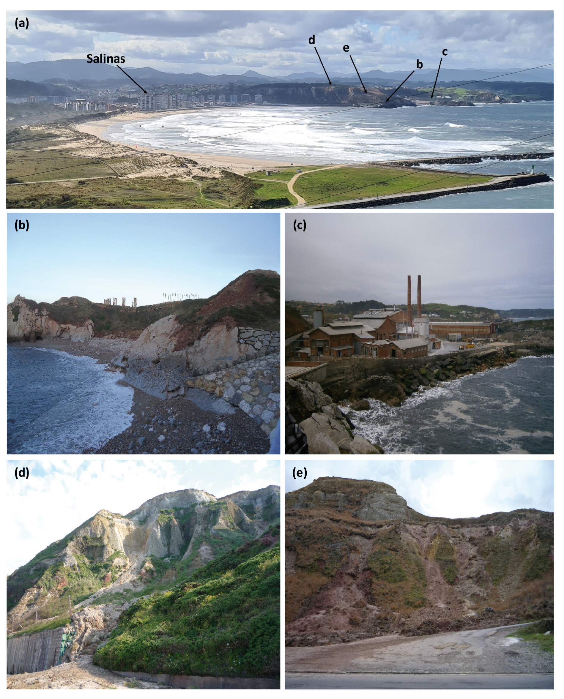
According to the BAPA database, there were a total of 78 slope instabilities between August 1993 and February 2019 in this area. The events were 29 flows (37.2%), 21 rockfalls (26.9%), 21 undetermined events (26.9%), 6 slides (7.7%), and 1 crack (1.3%). Their spatial distribution can be observed in Figure 7. Examples of three slope instabilities produced in this area are shown in Figure 6d,e. In addition, the majority of the landslide events were produced along the cliffs located between the town of Salinas and El Cuerno beach. Here, the slopes can exceed 60° in inclination. Their orientations are predominantly towards the N and E (0–135°).
Figure 7 shows the LOS mean velocity maps obtained by PSIG and GEP in the Salinas Area. According to PSIG measurements (Figure 7a, Table 4), the VLOS rates obtained range between −10.2 and 5.3 mm year−1. The total number of PS detected was 3417 (885.2 PS km−2). They were distributed between the urban, rock cliff, and outcrop reflectors. With respect to the accumulated displacement measured, a minimum and maximum of accumulation of -27.6 and 23.5 mm were detected. As to LOS rates measured, the stable PS represents 98.3% (3360 PS). In the case of negative PS (from −10.9 to −2.5 mm year−1), there are only 11 PS (0.3%). The positive PS with velocity rates of 2.5–4.6 mm year−1 (46 PS, 1.4%) stands out compared to those with negative deformation velocity, of which there were only 11 PS (0.3%). Moreover, all detected active PS were isolated and surrounded by stable PS. This makes it difficult to identify areas with deformation because the entire area can be considered as a sector without movement.
In the case of the LOS mean velocity map of GEP (Figure 7b, Table 4), the VLOS were between −7.4 to 9.8 mm year−1. The total number of PS was 459 (118.9 PS km−2). The accumulated displacements ranged from −17.1 to 18.9 mm. An important fact was the predominance of positive velocities (2.5 to 9.8 mm year−1, 167 PS, 36.4%). There were only 8 PS with negative velocities of −2.5 to −7.4 mm year−1 (1.7%). Stable PS represent 61.9 % of the total (284 PS). Besides, in both LOS mean velocity maps there was a massive lack of PS in the central area, due to the fact that there was a wooded area.
It can be appreciated that the A-DInSAR approaches have not detected ground movement in the problematic slope instability zone (Figure 7). In the case of PSIG, the few PS detected on these slopes show a LOS mean velocity of 1.2 mm year−1. Thus, we have chosen some deformation areas detected with GEP and have analyzed them with respect to PSIG and geospatial data in order to distinguish the movements linked to ground deformations from noise or other artifacts. Different time series were presented (Figure 7c) and were described below. The time series shown have been selected according to: (i) GEP deformations detected and (ii) the most representative deformations. Each deformation time series shows only one target, with the PS number, the mean VLOS (mm year−1) and the accumulated deformation (mm).
TSI: The TS measured by PSIG (TS-Ia, Figure 7c) do not present a deformation trend and their pattern is chaotic. The accumulated displacement is 4.2 mm. On the other hand, the GEP TS (TS-Ib, Figure 7c) presents a certain tendency of increasing deformation between January 2018 and May 2019. In this trend, the deformation achieves a displacement of 4 mm. However, there are some jumps in April and June 2018, and between May 2019 and February 2020 that make it difficult to read the TS. The accumulated deformation reaches a displacement of 2.4 mm. GEP TS presents a LOS mean velocity of 2.1 mm year−1.
TSII: situated in the Northeast of the Salinas area, in the town of Salinas itself. According to PSIG, the LOS velocity observed here is 2.8 mm year−1. On the other hand, 2.7 mm year−1 was measured by means of GEP. In the case of the PSIG, the TS (TS-IIa, Figure 7c) presented a period of increasing deformation between January 2018 and October 2018. The displacement measured was 4 mm. Afterward, there was a stabilization stage, from October 2018 to September 2019. Then, a time period with increasing deformation was recognizable until February 2020. The maximum accumulated displacement was 7.5 mm. On the other hand, according to GEP, the TS (TS-IIb, Figure 7c) shows a deformation period from January to October 2018. The achieved deformation was 4 mm. Later, there appears to be a stabilization until May 2019, when increasing deformation was registered for two months (until July 2019). Afterward, the trend presents two different patterns: firstly, it became stable until October 2019 and then chaotic from this month until February 2020. However, both patterns could be a stabilization stage with noise. The maximum displacement measured was 6.1 mm. A slope instability event has been recorded in the BAPA database. In June 2003, a collapse on the boardwalk of Salinas took place.
TSIII: located in the West of Salinas, near the slope. The LOS mean velocities detected were 1.9 mm year−1 and 3.5 mm year−1 by PSIG and GEP, respectively. The TS measured by PSIG (TS-IIIa, Figure 7c) showed a well-defined pattern. Firstly, it presented a rise in deformation between January 2018 and November 2018. The displacements reached 5–6 mm. Next, there was a stabilization step until February 2020. A small deformation spike (probably noise) can be observed in September 2019, with a displacement of 8 mm. During the mentioned stabilization period, the deformation continued, reaching values of up to 5.1 mm. However, the TS of GEP (TS-IIIb, Figure 7c) displayed a trend with increasing deformation from January 2018 to July 2019. The displacement reached 10 mm. From August 2019 the trend became more complex. There were some jumps with falls (until 2 mm) and rises in the deformation. During this period, the maximum accumulated displacement was 9.7 mm. In addition, in this place, there was an undetermined event in November 2003.

4. Discussion

PSIG and GEP approaches have been applied in the surroundings of Peñas Cape for the first time to increase the number of PS in the study area and to facilitate the analysis and interpretation of the detected deformation areas.
The results are discussed below in the following order: (i) PSIG and GEP results at a regional and local scale to detect and monitor coastal instabilities in cliff coast; (ii) observed relationships between coastal instabilities and coastal retreat in the study area; (iii) future research directions.
The LOS mean deformation velocity maps obtained by the two approaches (Figure 4 and Figure 5) allowed us to observe similar VLOS rates at a regional scale. PSIG has measured VLOS rates from −17.1 to 37.4 mm year−1 and GEP has measured VLOS rates from −23.0 to 38.3 mm year−1. Nevertheless, they present important differences in the interpretation of the obtained datasets at regional and local scales. Some of these differences are observed in the squared areas (Figure 6a,b) in Figure 4. These differences in A-DInSAR patterns are mainly that the number of positive PS on the GEP VLOS map (36.4% of positive PS with VLOS > 2.5 mm year−1) are greater than PSIG VLOS map (1.4% of positive PS of PSIG). The different results obtained by both approaches could be explained by the following factors; (1) the pixel resolution of software (14 × 4 m for the PSIG product versus 90 × 90 m for the GEP product), (2) the degree of selection and manipulation of the input parameters during the processing, (3) the technique implemented in each approach: thus, PSIG software is based on the PSI technique [2,3,56], while the GEP service has implemented the P-SBAS technique [1,62], (4) the variable amount, in each processing, of the uncorrected atmospheric component and (5) the location of the reference points.
Both approaches used have allowed the detection of different coastal instabilities at a regional scale (Figure 5). Firstly, in Figure 5a, the deformations (with VLOS rates between −12.4 and 0.6 mm year−1) are located in an electrical sub-station, in which ground movements have been related with slope instabilities that have developed on (i) destabilized slope and ii) anthropic fill settlements [63]. Secondly, different ground movements were detected in the Musel Port (Figure 5b), with VLOS rates between −8.6 and 6.3 mm year−1. These movements are produced by wave processes, tides, and the migration of sandy sediments. Additionally, being an area reclaimed from the sea, the deformations may be due to ground settlement taking place in the filler materials [64]. Positive accumulated ground motion trends can also be distinguished due to: i) accumulation of materials (anthropic activities) and (ii) different affections on the breakwater wall that produce a relative movement towards the satellite. Finally, GEP has allowed deformations to the West of Peñas Cape to be detected and identified (Figure 5c), with VLOS from −9.1 to 8.1 mm year−1. The affected materials are the bedrock and overlying rasa deposits. The authors of [45] indicate that the West of Peñas Cape shows the greatest coastal retreat in the area, with 13.38 m between 2006 and 2017. We suppose that these deformations, from −2.5 to −9.1 mm year−1, are due to coastal instabilities, which may be directly related to erosion of the cliff foot and undercutting sea action.
Other deformations detected reflect the accumulation of anthropic materials in open pits, works, and quarries, with VLOS greater than 5 mm year−1. In addition, some detected PS are associated with artifacts produced by uncorrected atmospheric components or processing errors. These processing errors, observed in some time series where there are jumps and aliasing effects, may be due to phase unwrapping.
Regarding local analysis, A-DInSAR processing has allowed us to distinguish local ground motions in all the selected areas. The Salinas area (Figure 3, Figure 4, Figure 6 and Figure 7) shows different deformations resulting from terrain instabilities detected thanks to the combined use of the two software tools. In this case, the GEP platform has detected more active PS than PSIG. In the first case, the detected deformations are directly produced by the effects of the sea on the shoreline (Figure 7c, TB-IIa and TB-IIb). The VLOS present rates from 2.7–2.8 mm year−1, with accumulated displacements of 6.1 and 7.5 mm. The coastline here is the seafront of Salinas, which was affected by severe storms [65]. These extreme episodes have produced collapses in the seafront and important beach and dune erosion [46,66]. According to [65], this area is located in a zone with high coastal recession and erosion. At this point, these authors have measured a change in the vertical distance between the top of the seafront promenade and the upper beach of −2.9 m between 1998 and 2010. In the second case (Figure 7c, TB-IIIa and TB-IIIb), the detected ground motion may be related to slope instabilities, since at this location, two mass movements occurred in November 2003 and June 2010 [46]. The involved materials are slope and rasa deposits, both composed of siliciclastic pebbles and abundant clay matrix.
In this study, we have demonstrated that the GEP service can be a useful tool to detect and monitor ground motion at a local scale. GEP had already proven itself as a powerful tool to identify and monitor soil instabilities on a regional scale [59]. However, it has not been possible to directly relate the areas prone to instabilities with the A-DInSAR results (Figure 7). With respect to this problem, we were able to observe and demonstrate the main limitation factors: (i) the orientation of the terrain; the principal zone of slope instabilities in Salinas presents a NE orientation (Figure 7), thus, slope movements are parallel to satellite sensor displacement direction. Therefore, these movements are practically impossible to detect by A-DInSAR. (ii) The high inclination of the slopes, which produces a foreshortening effect [67] and, therefore, a drastic reduction of the spatial resolution. (iii) The velocity of the landslide development; the nature of the slope instabilities, which are mainly rockfalls and flows, with movement velocities ranging from slow to extremely fast (>13 m month−1–>5 m s−1). Consequently, these slope instability typologies are undetectable by A-DInSAR [47].
Regarding Asturian coastal retreat data, at present, there are very few quantitative data, with rates ranging from 0.25 and 2.19 m year−1 [45]. These authors have evaluated different retreat rates in several local sectors (Table 5). In this research, we have identified different LOS velocity rates and LOS accumulated displacements for the same local areas (Table 5).
An important point to consider is that the zones reclaimed from the sea have a high incidence of movements and also significant damage to the civil and port infrastructures [68,69]. In this study, the most intense deformations have been found in the Musel port (Figure 4 and Figure 5B and Table 3). These ground motions are directly related to differential settlements in unconsolidated soils and coastal processes, as has been mentioned in other areas [69].
In addition, we should highlight that between 2006 and 2017, there were several important meteorological events. For example, in June 2010 and February 2014, there were storms and intense rainfall episodes. These events resulted in numerous instabilities and damage along the Asturian coast [44,45,46]. The majority of landslides registered [46] are rockfalls, flows, and undetermined events. According to [44,45], these movements were directly associated with littoral and gravity processes. However, as we mentioned above, these slope instabilities cannot be measured by A-DInSAR due to their high velocity and sudden development.
Finally, future research in the study area could be directed towards the application of the technologies and methodologies developed within the A-DInSAR techniques, such as: (i) application of the post-processing methodology proposed by [23,70], consisting in the definition, delimitation, and analysis of Active Deformation Areas (ADA) at both regional and local scales; (ii) conversion of VLOS measurements to VSLOPE values [14,71], a procedure that consists in the projection of the VLOS along the VSLOPE. It would allow the correction of the geometric distortions produced by the type of satellite orbit with respect to the terrain topography; (iii) new processing in ascending trajectories by means of both approaches used. This re-processing of the study area will help to explain and interpret the movements toward the sensors, which are difficult to interpret under the current research conditions.

5. Conclusions

First, A-DInSAR processing and analysis of the cliffs of the Central Coast of Asturias (N Spain) have been presented, using a dataset of 113 descending IW-SLC SAR images of Sentinel-1 A/B from January 2018 to February 2020. For the A-DInSAR processing, professional software (PSIG chain) and free unsupervised service (GEP platform) were applied. The principal aim of this work has been to detect and monitor coastal instabilities, differentiating and quantifying deformations related to slope instabilities from other ground movements or noise and atmospheric artifacts. Firstly, the ground motion analysis was conducted at regional scale. Afterwards, the deformations detected were analyzed at a local scale. The BAPA database has served as a key for the selection of the different local areas.
The main contribution of this work is to demonstrate that A-DInSAR techniques can be used to support the management of the coastal cliff areas at the regional scale. The BAPA database has served as a key for the selection of different areas at a local scale. These deformations can be directly related to coastal instabilities and effects on port infrastructures due to marine activity and infrastructure subsidence. The LOS mean deformation velocity maps (mm year−1) by means of PSIG and GEP show rates of −17.1–37.4 and −23.0–38.3 mm year−1, respectively. According to the deformation time series (mm), the minimum and maximum accumulated displacements are −68.5–78.8 and −48.8–77.0 mm by means of PSIG and GEP, respectively. These deformation movements could be related to coastal incidence and retreat. Other deformations that were found are due to anthropic activities and uncorrected atmospheric component.
This study considerably improves the previous knowledge of coastal instabilities and other ground motions along the Central cliff coast of Asturias. The factors that limit the application of A-DInSAR in the study area are: (i) the geometry and characteristics of the cliffs of the Asturian coast in relation to satellite trajectories and (ii) the nature of the landslides (rockfalls, flows and undetermined events) occurring over the study area.
Future research will involve improving the interpretation of the A-DInSAR dataset, by means of re-processing in ascending trajectories, the application of the ADA methodology and the estimation of the VSLOPE from VLOS measurements obtained in this work. These techniques will contribute to improving the future management of the Asturian Coast.

Author Contributions

Conceptualization, J.C.-M., M.J.D.-C. and F.M.R.; methodology, J.C.-M.; software, J.C.-M., A.B. and O.M.; validation, J.C.-M.; formal analysis, J.C.-M.; investigation, J.C.-M.; resources, J.C.-M., M.J.D.-C., P.V., A.B. and O.M.; data curation, J.C.-M., M.J.D.-C., P.V., A.B. and O.M.; writing—original draft preparation, J.C.-M.; writing—review and editing, J.C.-M., M.J.D.-C., F.M.R., A.B., O.M., P.V. and M.J.-S.; visualization, J.C.-M.; supervision, J.C.-M., M.J.D.-C.; project administration, M.J.D.-C., F.M.R. and M.J.-S.; funding acquisition, M.J.D.-C. and M.J.-S. All authors have read and agreed to the published version of the manuscript.

Funding

This research was funded by COSINES Project Ref. CGL2017-83909-R, Call 2017 for RETOS Projects funded by the Spanish Economy, Industry and Competitiveness Ministry-Ministerio de Economía, Industria y Competitividad (MINECO), the Spanish Research Agency-Agencial Estatal de Investigación (AEI) and the European Regional Development Fund (FEDER).

Data Availability Statement

Not applicable.

Acknowledgments

We really appreciate the suggestions and comment of two anonymous referees that have contributed substantially to improving this manuscript.

Conflicts of Interest

The authors declare no conflict of interest.

References

  1. Casu, F.; Elefante, S.; Imperatore, P.; Zinno, I.; Manunta, M.; De Luca, C.; Lanari, R. SBAS-DInSAR parallel processing for deformation time-series computation. IEEE J. Sel. Top. Appl. Earth Obs. Remote Sens. 2014, 7, 3285–3296. [Google Scholar] [CrossRef]
  2. Ferreti, A.; Prati, C.; Rocca, F. Nonlinear subsidence rate estimation using Permanent Scatterers in Differential SAR Interferometry. IEEE Trans. Geosci. Remote Sens. 2000, 38, 2202–2212. [Google Scholar] [CrossRef] [Green Version]
  3. Ferreti, A.; Prati, C.; Rocca, F. Permanent Scatterers in SAR interferometry. IEEE Trans. Geosci. Remote Sens. 2001, 39, 8–20. [Google Scholar] [CrossRef]
  4. Berardino, P.; Fornaro, G.; Lanari, R.; Sansosti, E. A New Algorithm for Surface Deformation Monitoring Based on Small Baseline Differential SAR Interferograms. IEEE Trans. Geosci. Remote Sens. 2002, 40, 2375–2383. [Google Scholar] [CrossRef] [Green Version]
  5. Crosetto, M.; Monserrat, O.; Cuevas-González, M.; Devanthéry, N.; Crippa, B. Persistent Scatterer Interferometry: A review. ISPRS J. Photogramm. Remote Sens. 2015, 115, 78–89. [Google Scholar] [CrossRef] [Green Version]
  6. Hooper, A.; Zebker, H.A.; Segall, P.; Kampes, B. A new method for measuring deformation on volcanoes and other natural terrains using InSAR persistent scatterers. Geophys. Res. Lett. 2004, 31, L23611. [Google Scholar] [CrossRef]
  7. De Novellis, V.; Carlino, S.; Castaldo, R.; Tramelli, A.; De Luca, C.; Pino, N.A.; Pepe, S.; Convertito, V.; Zinno, I.; De Martino, P.; et al. The 21 August 2017 Ischia (Italy) Earthquake Source Model Inferred From Seismological, GPS, and DInSAR Measurements. Geophys. Res. Lett. 2017, 45, 2193–2202. [Google Scholar] [CrossRef]
  8. Béjar-Pizarro, M.; Álvarez-Gómez, J.A.; Staller, A.; Luna, M.P.; Pérez-López, R.; Monserrat, O.; Chunga, K.; Lima, A.; Galve, J.P.; Martínez-Díaz, J.J.; et al. InSAR-Based Mapping to Support Decision-Making after an Earthquake. Remote Sens. 2018, 10, 899. [Google Scholar] [CrossRef] [Green Version]
  9. Raucoules, D.; Colesanti, C.; Carnec, C. Use of SAR interferometry for detecting and assessing ground subsidence. Comptes Rendus Geosci. 2007, 339, 289–302. [Google Scholar] [CrossRef]
  10. Sanabria, M.P.; Guardiola-Albert, C.; Tomás, R.; Herrera, G.; Prieto, A.; Sánchez, H.; Tessitore, S. Subsidence activity maps derived from DInSAR data: Orihuela case study. Nat. Hazards Earth Syst. Sci. 2014, 14, 1341–1360. [Google Scholar] [CrossRef] [Green Version]
  11. Solari, L.; Ciampalini, A.; Raspini, F.; Bianchini, S.; Moretti, S. PSInSAR Analysis in the Pisa Urban Area (Italy): A Case of Study of Subsidence Related to Stratigraphical Factors and Urbanization. Remote Sens. 2016, 8, 120. [Google Scholar] [CrossRef] [Green Version]
  12. Solari, L.; Del Soldato, M.; Bianchini, S.; Ciampalini, A.; Ezquerro, P.; Montalti, R.; Raspini, F.; Moretti, S. From ERS 1/2 to Sentinel-1: Subsidence Monitoring in Italy in the Last Two Decades. Front. Earth Sci. 2018, 6, 149. [Google Scholar] [CrossRef]
  13. Cascini, L.; Fornaro, G.; Peduto, D. Advanced low- and full-resolution DInSAR map generation for slow-moving landslide analysis at different scales. Eng. Geol. 2010, 112, 29–42. [Google Scholar] [CrossRef]
  14. Bianchini, S.; Herrera, G.; Mateos, R.M.; Notti, D.; Garcia, I.; Mora, O.; Moretti, S. Landslide Activity Maps Generation by Means of Persistent Scatterer Interferometry. Remote Sens. 2013, 5, 6198–6222. [Google Scholar] [CrossRef] [Green Version]
  15. Herrera, G.; Gutiérrez, F.; García-Davalillo, J.C.; Guerrero, J.; Notti, D.; Galve, J.P.; Fernández-Merodo, J.A.; Cooksley, G. Multi-sensor advanced DInSAR monitoring of very slow landslides: The Tena Valley case study (Central Spanish Pyrenees). Remote Sens. Environ. 2013, 128, 31–43. [Google Scholar] [CrossRef]
  16. Barra, A.; Monserrat, O.; Mazzanti, P.; Esposito, C.; Crosetto, M.; Scarascia-Mugnozza, G. First insights on the potential of Sentinel-1 for landslides detection. Geomat. Nat. Hazards Risk 2016, 7, 1874–1883. [Google Scholar] [CrossRef] [Green Version]
  17. Bell, J.W.; Amelung, F.; Ferreti, A.; Bianchi, M.; Novali, F. Permanent Scatterer InSAR reveals seasonal and long-term aquifer-system response to groundwater pumping and artificial recharge. Water Resour. Res. 2008, 44, W02407. [Google Scholar] [CrossRef] [Green Version]
  18. Béjar-Pizarro, M.; Ezquerro, P.; Herrera, G.; Tomás, R.; Guardiola-Albert, C.; Ruíz Hernández, J.M.; Fernández Merodo, J.A.; Marchamalo, M.; Martínez, R. Mapping groundwater level and aquifer storage variations from InSAR measurements in the Madrid aquifer, Central Spain. J. Hydrol. 2017, 547, 678–689. [Google Scholar] [CrossRef] [Green Version]
  19. Haghighi, M.H.; Motagh, M. Ground surface response to continuous compaction of aquifer system in Tehran, Iran: Results from a long-term multi-sensor InSAR analysis. Remote Sens. Environ. 2019, 221, 534–550. [Google Scholar] [CrossRef]
  20. Perissin, D.; Wang, Z.; Lin, H. Shangai subway tunnels and highways monitoring through Cosmo-SkyMed Persistent Scatterers. ISPRS J. Photogram. Remote Sens. 2012, 73, 58–67. [Google Scholar] [CrossRef]
  21. Del Soldato, M.; Tomás, R.; Pont, J.; Herrera, G.; García-Davalillos, J.C.; Mora, O. A multi-sensor approach for monitoring a road bridge in the Valencia harbour (SE Spain) by SAR Interferometry (InSAR). Rend. Online Della Soc. Geol. Ital. 2016, 41, 235–238. [Google Scholar] [CrossRef] [Green Version]
  22. Chang, L.; Dollevoet, R.P.; Hanssen, R.F. Nationwide Railway Monitoring Using Satellite SAR Interferometry. IEEE J. Sel. Top. Appl. Earth Obs. Remote Sens. 2017, 10, 596–604. [Google Scholar] [CrossRef]
  23. Barra, A.; Solari, L.; Béjar-Pizarro, M.; Monserrat, O.; Bianchini, S.; Herrera, G.; Crosetto, M.; Sarro, R.; González-Alonso, E.; Mateos, R.M.; et al. Methodology to Detect and Update Active Deformation Areas Based on Sentinel-1 SAR Images. Remote Sens. 2017, 9, 1002. [Google Scholar] [CrossRef] [Green Version]
  24. Rott, H. Advances in interferometric synthetic aperture radar (InSAR) in earth system science. PPG Earth Environ. 2009, 33, 769–791. [Google Scholar] [CrossRef]
  25. Sunamura, T. Geomorphology of Rocky Coasts; John Wiley and Sons: Chichester, UK, 1992; p. 302. [Google Scholar]
  26. Trenhaile, A.S. Modeling the development of marine terraces on tectonically mobile rock coasts. Mar. Geol. 2002, 185, 341–361. [Google Scholar] [CrossRef]
  27. Gómez-Puyol, L.; Pérez-Alberti, A.; Blanco-Chao, R.; Costa, S.; Neves, M.; Del Río, L. The rock coast of continental Europe in the Atlantic. In Rock Coast Geomorphology: A Global Synthesis; Kennedy, D.M., Stephenson, W.J., Naylor, L., Eds.; Geological Society London Memoirs: London, UK, 2014; Volume 40, pp. 77–87. [Google Scholar]
  28. Flor, G.; Flor-Blanco, G.; Rey, J. Dynamics and morpho-sedimentary interactions in the lower mesotidal estuary of Villaviciosa (NW Spain): A management proposal. Geol. Acta 2015, 13, 107–121. [Google Scholar] [CrossRef]
  29. Trenhaile, A. Rocky coasts—their role as depositional environments. Earth Sci. Rev. 2016, 159, 1–13. [Google Scholar] [CrossRef]
  30. Epifânio, B.; Zêzere, J.L.; Neves, M. Identification of hazardous zones combining cliff retreat rates with landslide susceptibility assessment. J. Coast. Res. 2013, 65, 1681–1686. [Google Scholar] [CrossRef] [Green Version]
  31. Michoud, C.; Carrea, D.; Costa, S.; Derron, M.H.; Jaboyedoff, M.; Delacourt, C.; Maquaire, O.; Letortu, P.; Davidson, R. Landslide detection and monitoring capability of boat-based mobile laser scanning along Dieppe coastal cliffs, Normandy. Landslides 2015, 12, 403–418. [Google Scholar] [CrossRef]
  32. Boualla, O.; Mehdi, K.; Fadili, A.; Makan, A.; Zourarah, B. GIS-based landslide susceptibility mapping iin the Safi region, West Morocco. Bull. Eng. Geol. Environ. 2019, 78, 2009–2026. [Google Scholar] [CrossRef]
  33. Horacio, J.; Muñoz-Narciso, E.; Trenhaile, A.; Pérez-Alberti, A. Remote sensing monitoring of a coastal-valley earthflow in northwestern Galicia, Spain. Catena 2019, 178, 276–287. [Google Scholar] [CrossRef]
  34. Notti, D.; Galve, J.P.; Mateos, R.M.; Monserrat, O.; Lamas-Fernández, F.; Fernández-Chacón, F.; Roldán-García, F.J.; Pérez-Peña, J.V.; Crosetto, M.; Azañón, J.M. Human-induced coastal Landslide reactivation. Monitoring by PSInSAR techniques and urban damage survey (SE Spain). Landslides 2015, 12, 1007–1014. [Google Scholar] [CrossRef]
  35. Cigna, F.; Banks, V.; Donald, A.W.; Donohue, S.; Graham, C.; Hughes, D.; McKinley, J.M.; Parker, K. Mapping Ground Instability in Areas of Geotechnical Infraestructure Using Satellite InSAR and Small UAV Surveying: A Case Study in Northern Ireland. Geosciences 2017, 7, 51. [Google Scholar] [CrossRef] [Green Version]
  36. Mateos, R.M.; Ezquerro, P.; Azañón, J.M.; Gelabert, B.; Herrera, G.; Fernández-Merodo, J.A.; Spizzichino, D.; Sarro, R.; García-Moreno, I.; Béjar-Pizarro, M. Coastal lateral spreading in the world heritage site of the Tramuntana Range (Majorca, Spain). The use of PSInSAR monitoring to identify vulnerability. Landslides 2018, 15, 797–809. [Google Scholar] [CrossRef]
  37. Spinosa, A.; Ziemba, A.; Saponieri, A.; Navarro-Sanchez, V.D.; Damiani, L.; El Serafy, G. Automatic Extraction of Shoreline from Satellite Images: A new approach. In Proceedings of the IEEE International Workshop on Metrology for the Sea; Learrning to Measure Sea Health Parameters (MetroSea) 2018, Bari, Italy, 8–10 October 2018; pp. 33–38. [Google Scholar] [CrossRef]
  38. Solari, L.; Barra, A.; Herrera, G.; Bianchini, S.; Monserrat, O.; Béjar-Pizarro, M.; Crosetto, M.; Sarro, R.; Moretti, S. Fast detection of ground motions on vulnerable elements using Sentinel-1 InSAR data. Geomat. Nat. Hazards Risk 2018, 9, 152–174. [Google Scholar] [CrossRef] [Green Version]
  39. Atanasova, M.; Nikolov, H. Detection of ground motions in coastal area. In Proceedings of the XXIX International Symposium on “Modern Technologies, Education and Professional Practice in Geodesy and Related Fields” 2019, Istanbul, Turkey, 5–6 November 2019. [Google Scholar] [CrossRef]
  40. Yu, L.; Yang, T.; Zhao, Q.; Liu, M.; Pepe, A. The 2015-2016 Ground Displacements of the Shangai Coastal Area Inferred from a Combined COSMO-SkyMed/Sentinel-1 DInSAR Analysis. Remote Sens. 2017, 9, 1194. [Google Scholar] [CrossRef] [Green Version]
  41. Krishnan, S.; Kim, D.; Jung, J.; Cho, Y.K. Application of PS-InSAR Technique for Measuring the Coastal Subsidence in the East Coast of South Korea. In Proceedings of the URSI Asia-Pacific Radio Science Conference 2019, New Delhi, India, 9–15 March 2019. [Google Scholar] [CrossRef]
  42. Cian, F.; Delgado-Blasco, J.M.; Carrera, L. Sentinel-1 for Monitoring Land Subsidence of Coastal Cities in Africa Using PSInSAR: A Methodology Based on the Integration of SNAP and StaMPS. Geosciences 2019, 9, 124. [Google Scholar] [CrossRef] [Green Version]
  43. Domínguez-Cuesta, M.J.; Jiménez-Sánchez, M.; González-Fernández, J.A.; Quintana, L.; Flor, G.; Flor-Blanco, G. GIS as a tool to detect flat erosional surfaces in coastal areas: A case study in North Spain. Geol. Acta 2015, 13, 97–106. [Google Scholar] [CrossRef]
  44. Domínguez-Cuesta, M.J.; Valenzuela, P.; Rodríguez-Rodríguez, L.; Ballesteros, D.; Jiménez-Sánchez, M.; Piñuela, L.; García-Ramos, J.C. Cliff Coast of Asturias. In The Spanish Coastal System. Dynamic Processes, Sediments and Management; Morales, J.A., Ed.; Springer Nature Switzerland AG: Cham, Switzerland, 2019; pp. 49–77. [Google Scholar] [CrossRef]
  45. Domínguez-Cuesta, M.J.; Ferrer-Serrano, A.; Rodríguez-Rodríguez, L.; López-Fernández, C.; Jiménez-Sánchez, M. Análisis del retroceso de la costa cantábrica en el entorno del Cabo Peñas (Asturias, N España). Geogaceta 2020, 68, 63–66. [Google Scholar]
  46. Valenzuela, P.; Domínguez-Cuesta, M.J.; Mora, M.; Jiménez-Sánchez, M.A. spatio-temporal Landslide inventory for the NW of Spain: BAPA database. Geomorphology 2017, 293, 11–23. [Google Scholar] [CrossRef] [Green Version]
  47. Canuti, P.; Casagli, N.; Ermini, L.; Fanti, R.; Farina, P. Landslide activity as a geoindicator in Italy: Significance and new perspectives from remote sensing. Environ. Geol. 2004, 45, 907–919. [Google Scholar] [CrossRef]
  48. Instituto Nacional de Estadística (INE). Demografía y Población. Available online: https://www.ine.es/dyngs/INEbase/es/categoria.htm?c=Estadistica_P&cid=1254734710984 (accessed on 23 November 2020).
  49. Flor, G.; del Busto, J.A.; Flor-Blanco, G. Morphological and Sedimentary Patterns of Ports of the Asturian Region (NW Spain). J. Coast. Res. 2006, 48, 35–40. [Google Scholar]
  50. AEMET. Agencia Estatal de Meteorología. Available online: http://www.aemet.es/es/portada (accessed on 1 December 2020).
  51. Flor, G. Las Rasas Asturianas: Ensayos de Correlación y Emplazamiento. Trab. Geol. 1983, 13, 65–81. [Google Scholar]
  52. Flor, G.; Flor-Blanco, G. Raised beaches in the Cantabrian Coast. In Landscapes and Landsforms of Spain; Gutiérrez, F., Gutiérrez, M., Eds.; Springer Nature Switzerland AG: Chan, Switzerland, 2014; pp. 1–10. [Google Scholar] [CrossRef]
  53. Julivert, M. La estructura de la región de Cabo Peñas. Trab. Geol. 1976, 8, 203–309. [Google Scholar]
  54. Truyols, J.; Julivert, M. La sucesión paleozoica entre Cabo Peñas y Antromero (Cordillera Cantábrica). Trab. Geol. 1976, 8, 5–30. [Google Scholar]
  55. Arbizu, M.; Aller, J.; Méndez-Bedia, I. Rasgos geológicos de la región del Cabo Peñas. In Geología de Asturias, 1st ed.; Aramburu, C., Bastida, F., Eds.; Ediciones TREA S.L.: Gijón, Spain, 1995; pp. 231–246. [Google Scholar]
  56. Biescas, E.; Crosetto, M.; Agudo, M.; Monserrat, O.; Crippa, B. Two Radar Interferometric Approaches to Monitor Slow and Fast Land Deformation. J. Surv. Engrg. 2007, 133, 66–71. [Google Scholar] [CrossRef]
  57. Devanthéry, N.; Crosetto, M.; Monserrat, O.; Cuevas-González, M.; Crippa, B. An Approach to Persistent Scatterer Interferometry. Remote Sens. 2014, 6, 6662–6679. [Google Scholar] [CrossRef] [Green Version]
  58. Devanthéry, N.; Crosetto, M.; Monserrat, O.; Crippa, B.; Mróz, M. Data analysis tools for persistent scatterer interferometry based on Sentinel-1 data. Eur. J. Remote Sens. 2019, 52, 15–25. [Google Scholar] [CrossRef] [Green Version]
  59. Galve, J.P.; Pérez-Peña, J.V.; Azañón, J.M.; Closson, D.; Caló, F.; Reyes-Carmona, C.; Jabaloy, A.; Ruano, P.; Mateos, R.M.; Notti, D.; et al. Evaluation of the SBAS InSAR Service of the European Space Agency´s Geohazard Exploitation Platform (GEP). Remote Sens. 2017, 9, 1291. [Google Scholar] [CrossRef] [Green Version]
  60. Geohazards-TEP. Geohazard Exploitation Platform. Available online: https://geohazards-tep.eu/#! (accessed on 1 December 2020).
  61. Meisina, C.; Zucca, F.; Notti, D.; Colombo, A.; Cucchi, A.; Savio, G.; Giannico, C.; Bianchi, M. Geological Interpretation of PSInSAR Data at Regional Scale. Sensors 2008, 8, 7469–7492. [Google Scholar] [CrossRef] [Green Version]
  62. Manunta, M.; Bonano, M.; Buonanno, S.; Casu, F.; De Luca, C.; Fusco, A.; Lanari, R.; Manzo, M.; Ojha, C.; Pepe, A.; et al. Unsupervised Parallel SBAS-DInSAR Chain for Massive and Systematic Sentinel-1 Data Processing. In Proceedings of the IEEE International Geoscience and Remote Sensing Symposium IGARSS, Beijing, China, 10–15 July 2016; pp. 3890–3893. [Google Scholar] [CrossRef]
  63. Uriel-Ortiz, A. Patología de las cimentaciones. Inf. Construcción 1983, 35, 5–35. [Google Scholar] [CrossRef] [Green Version]
  64. Almazán-Gárate, J.L.; Palomino-Monzón, M.C. Introducción a la ingeniería Portuaria: Sistema Portuario Español. Obras Exteriores; Universidad Politécnica de Madrid: Madrid, Spain, 2000; pp. 11–16. [Google Scholar]
  65. Flor, G.; Flor-Blanco, G. An Introduction to the erosion and sedimentation problems in the coastal regions of Asturias and Cantabria (NW Spain) and its implications on environmental management. J. Coast. Res. 2005, 49, 58–63. [Google Scholar]
  66. Flor-Blanco, G.; Flor, G.; Pando, L. Evolution of the Salinas-El Espartal and Xagó beach/dune systems in north-western Spain over recent decades: Evidence for responses to natural processes and anthropogenic interventions. Geo Mar. Lett. 2013, 33, 143–157. [Google Scholar] [CrossRef]
  67. Colesanti, C.; Wasowski, J. Investigating landslides with space-borne Synthetic Aperture Radar (SAR) interferometry. Eng. Geol. 2006, 88, 173–199. [Google Scholar] [CrossRef]
  68. Zhao, Q.; Lin, H.; Gao, W.; Zebker, H.A.; Chen, A.; Yeung, K. InSAR detection of residual settlement of an ocean reclamation engineering project: A case study of Hong Kong International Airport. J. Oceanogr. 2011, 67, 415–426. [Google Scholar] [CrossRef]
  69. Zhao, Q.; Pepe, A.; Gao, W.; Lu, Z.; Bonano, M.; He, M.L.; Wang, J.; Tang, X. A DInSAR Investigation of the Ground Settlement Time Evolution of Ocean-Reclaimed Lands in Shangai. IEEE J. Sel. Top. Appl. Earth Obs. Remote Sens. 2015, 8, 1763–1781. [Google Scholar] [CrossRef]
  70. Navarro, J.A.; Tomás, R.; Barra, A.; Pagán, J.I.; Reyes-Carmona, C.; Solari, L.; Vinielles, J.L.; Falco, S.; Crosetto, M. ADAtools: Automatic Detection and Classification of Active Deformation Areas from PSI Displacement Maps. ISPRS Int. J. Geo Inf. 2020, 9, 584. [Google Scholar] [CrossRef]
  71. Bianchini, S.; Herrera, G.; Mateos, R.M.; García-Moreno, I.; Mora, O.; Sanchez, C.; Sanabria, M.; López, M.; Merodo, J.A.; Hernández, M.; et al. Metodología para mejorar el análisis de datos satélite radar en el estudio de los movimientos de ladera: Resultados del proyecto FP7 DORIS en la Serra de Tramuntana (Mallorca). In Proceedings of the VIII Simposio Nacional sobre Taludes y Laderas Inestables, Palma de Mallorca, Spain, 11–14 June 2013. [Google Scholar]
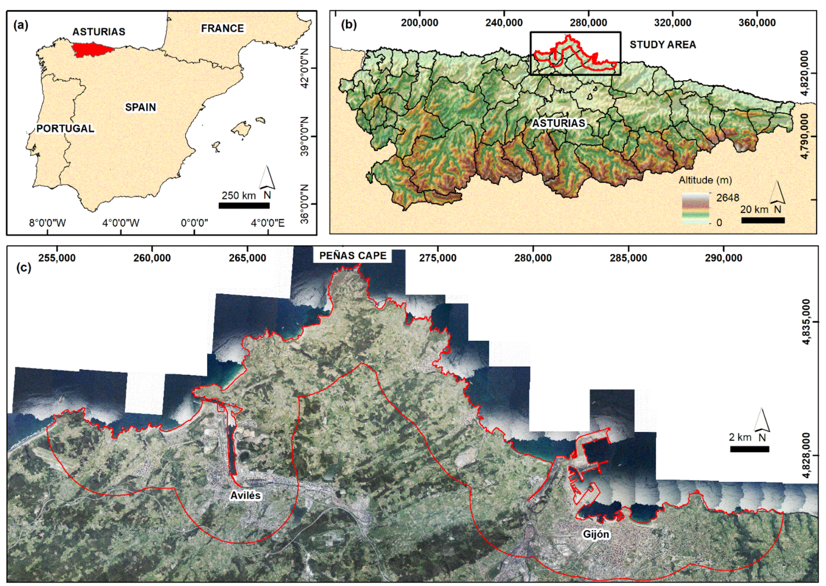
Figure 1. (a) Location of Asturias in the N of Spain; (b) central coast of Asturias study area; (c) study area, with principal cities of Avilés and Gijón and the Peñas Cape location; OrtoPNOA 2017 CC-BY 4.0 scne.es.
Remotesensing 13 03076 g001
Figure 2. Flow diagram of the procedure and tools used in this work.
Remotesensing 13 03076 g002
Figure 3. Geographical distribution of coastal slope instabilities registered in the BAPA database [46] between 1980 to 2019. Red rectangles indicate areas studied more in depth: A-Salinas Town, B-Podes Peninsula, C-Luanco Town, D-Candás Town, E-Musel Port and F-Peñarrubia Beach. DEM with 5 × 5 m pixel resolution.
Remotesensing 13 03076 g003
Figure 4. (a) LOS mean deformation velocity map in mm year−1 obtained by PSIG software; (b) LOS mean deformation velocity map in mm year−1 obtained by GEP service; the red squares are the selected deformation areas for local analysis. OrtoPNOA 2017 CC-BY 4.0 scne.es.
Remotesensing 13 03076 g004
Figure 5. (a) Deformations detected in an electrical sub-station (Avilés city) through some observed time series obtained by PSIG software; (b) PSIG deformations measured in Musel Port (Gijón city) showing some representative time series; (c) GEP and PSIG PS detected in a cliff area. See locations in Figure 4. OrtoPNOA 2017 CC-BY 4.0 scne.es.
Remotesensing 13 03076 g005
Figure 6. Salinas area views. (a) Salinas town panorama; (b) cliffs and beach of La Peñona; (c) industries located at the El Cuerno beach; (d) and (e) debris flows on the Salinas-La Peñona road in 2010 and 2008, respectively.
Remotesensing 13 03076 g006
Figure 7. Salinas town. (a) LOS mean deformation velocity map by PSIG chain; (b) LOS mean deformation velocity map by GEP service; (c) Deformation time series obtained by PSIG and GEP. OrtoPNOA 2017 CC-BY 4.0 scne.es.
Remotesensing 13 03076 g007
Table 1. Main acquisition parameters of the SAR satellite dataset used and principal processing parameters of both approaches.
SatelliteSentinel-1
SensorA/B
BandC
Wavelength5.55 cm
Acquisition modeWide Swath
PolarizationVV
SAR productSingle Look Complex
Acquisition orbitDescending
Temporal period4 January 2018–5 February 2020
Revisit period6–12 days
Resolution14 × 4 m
Incidence angle39°
Track154
Number of SAR images113
Processing ParametersPSIGGEP
A-DInSAR techniquePSIP-SBAS
Pixel Resolution14 × 4 m90 × 90 m
Pixel selection criteriaAmplitudeCoherence
Reference Point−5.862760/43.364576−5.8430905/43.368119
Used DEMSRTM_35_04 (90 m)SRTM_1arcsec (30 m)
Multilooking Factor1 × 1 (Azimuth × Range)5 × 20 (Azimuth × Range)
Applied FilterLPSAPS
Table 2. Main characteristics of PSIG and GEP processing and A-DInSAR dataset: Statistics of LOS mean deformation velocity rates (mm year−1) and accumulated LOS deformation (mm).
STUDY AREAPSIG Software GEP Service
Number of points (PS)151,722 16,654
Density of points (PS km−2)811.3 89.1
LOS velocity (mm year−1)
Mean 0.0 0.0
Maximum37.4 38.3
Minimum−17.1 −23.0
Standard deviation1.1 2.6
Accumulated LOS deformation (mm)
Mean0.1 1.1
Maximum78.8 77.0
Minimum−68.5 −48.8
Standard deviation3.6 5.1
LOS Rates PSIG
(mm Year−1)
PSIG
PS–%
LOS Rates GEP
(mm Year−1)
PS–% GEP
<−10.0 15–0.010<−10.0 49–0.29
−10.0–−5.0 184–0.12−10.0–−5.0 513–3.08
−5.0–−2.52049–1.35−5.0–−2.51295–7.78
−2.5–2.5146,855–96.79−2.5–2.516,654–74.53
2.5–5.02426–1.602.5–5.01956–11.74
5.0–10.0167–0.115.0–10.0385–2.31
>10.026–0.02>10.043–0.26
Table 3. A-DInSAR results for each local area selected: #PS—Number of points detected; VLOS—LOS mean deformation velocity rates in mm year−1; TS—minimum and maximum deformation accumulated in mm.
Local
Areas
Area
km2
PS km−2PS km−2PSIG SoftwareGEP Service
PSIGGEP#PSVLOSTS#PSVLOSTS
Salinas town3.9876.2117.73417−10.9−4.6−27.6–23.5459−7.4–9.8−17.1–18.9
Podes
Peninsula
2.88.930.4251.5–4.51.6–10.785−6.8–12.9−13.7–28.9
Luanco town8.1509.564.74127−4.6–7.4−28.0–27.0524−10.9–8.9−15.1–19.0
Candás town7.5479.760.93598−4.7–6.2−27.7–22.2457−11.6–9.1−18.6–18.7
Musel Port4.7850.0102.63995−17.1–6.0−53.6–33.6482−12.3–9.7−26.8–32.1
Peñarrubia
Beach
11.6364.063.94222−6.3–4.6−22.3–23.7741−12.6–8.7−28.0–15.4
Table 4. LOS mean deformation velocity rates (mm year−1), number of PS with their percentages.
LOS Mean Velocity Rates (mm Year−1)PS–% PSIGPS–% GEP
<−2.5 11–0.38–1.7
−2.5–2.5 3360–98.3284–61.9
> 2.5 46–1.4167–36.4
Table 5. Maximum coastal retreat rate (2006-2017) [45], LOS mean velocity and maximum LOS accumulated displacements (2018-2020) for some local sectors.
SectorMaximum
Coastal Retreat Rate
(m Year−1)
LOS Velocity
(mm Year−1)
LOS Displacement
(mm)
PSIGGEPPSIGGEP
Podes Peninsula 0.71No data−6.8–12.9No data−13.7–28.9
Luanco town 1.22−2–3.7−9.1–7.5−15.8–26.6−12.9–16.3
Candás town0.78−1.7–1.2−5.6–7.5−3.9–10.1−8.9–10.4
Publisher’s Note: MDPI stays neutral with regard to jurisdictional claims in published maps and institutional affiliations.