Abstract
The global climate shift currently underway has significant impacts on both the quality and quantity of snow precipitation. This directly influences the spatial variability of the snowpack as well as cumulative snow height. Contemporary glacier retreat reorganizes periglacial morphology: while the glacier area decreases, the moraine area increases. The latter is becoming a new water storage potential that is almost as important as the glacier itself, but with considerably more complex topography. Hence, this work fills one of the missing variables of the hydrological budget equation of an arctic glacier basin by providing an estimate of the snow water equivalent (SWE) of the moraine contribution. Such a result is achieved by investigating Structure from Motion (SfM) image processing that is applied to pictures collected from an Unmanned Aerial Vehicle (UAV) as a method for producing snow depth maps over the proglacial moraine area. Several UAV campaigns were carried out on a small glacial basin in Spitsbergen (Arctic): the measurements were made at the maximum snow accumulation season (late April), while the reference topography maps were acquired at the end of the hydrological year (late September) when the moraine is mostly free of snow. The snow depth is determined from Digital Surface Model (DSM) subtraction. Utilizing dedicated and natural ground control points for relative positioning of the DSMs, the relative DSM georeferencing with sub-meter accuracy removes the main source of uncertainty when assessing snow depth. For areas where snow is deposited on bare rock surfaces, the correlation between avalanche probe in-situ snow depth measurements and DSM differences is excellent. Differences in ice covered areas between the two measurement techniques are attributed to the different quantities measured: while the former only measures snow accumulation, the latter includes all of the ice accumulation during winter through which the probe cannot penetrate, in addition to the snow cover. When such inconsistencies are observed, icing thicknesses are the source of the discrepancy that is observed between avalanche probe snow cover depth measurements and differences of DSMs.
Keywords:
snowcover; snow water equivalent; cryosphere; moraine; arctic; UAV-SfM; spatial dynamics; photogrammetry 1. Introduction
Cryosphere dynamics are highly dependent on snowcover processes, which trigger further hydrological processes. Snowmelt runoff is part of fresh water fluxes reaching oceans and, thus, is strongly linked with snowpack spatio-temporal variability over a season [1,2]. Furthermore, in certainn environments, such as mountainous regions, snowpack dynamics often dominate water storage and release [3], which strongly influences geomorphological adaptation. In the high Arctic, year-after-year, a glacier retreat trend is generally observed, while the area of the proglacial moraine increases at the same time [4,5]. Consequently, the corresponding snowpack surface on ice-free ground also becomes wider. With respect to a glacial hydro-system, this pro-glacial moraine area should now be considered to be an increasingly important contributor to outflows in addition to the glacier snowpack itself [6,7]. However, snowpack in the moraine is much more challenging to monitor due to the glacier forefield topographical characteristics. Indeed, the micro and local rough topography result in a high degree of seasonal and inter-annual variability in spatial distribution [8]. Snow banks and massive accumulations contrast with a convex areas which are particularly eroded by the wind or influenced by black-body effect [9].
In addition to such considerations, ongoing dynamics that are induced by climate shift imply an increase of short events with long lasting consequences, such as rain on snow [10], wind effects [11], or even sudden heavy snowfalls [12]. The occurrence of these phenomena is observed to increase over time, strongly contributing to the modification of snowcover dynamics [13].
In the specific case of a morainic structure, collecting snow cover data that are representative of the spatial distribution of snow depth is challenging due to topographic discontinuities. Thus, remote sensing methods could be considered to be an alternative or, better still, a complement to ground observations. In recent years, the use of unmanned aerial vehicle (UAV) data acquisition has emerged as a well suited method for investigating geomorphological changes due to climate shift [14,15]. Similarly, cryospheric processes can also be measured quite accurately [16,17,18,19]. According to these works, the use of combined UAV with Structure from Motion (SfM) data processing is well suited for the glacial/periglacial environment [20,21,22], and especially when following fast and short processes [23,24] tha last a few hours to a few days, such as flash floods inducing large transfers of sediments and carving canyons in the moraine, or washing away the snow cover that took weeks to months to accumulate in only a few hours. In addition, in past works [25] we showed that, in the Arctic, climatic conditions as well as harsh field campaigns need a flexible means for carrying out a monitoring task: a UAV is deployed on short notice in less than a couple of hours, the time that is needed to reach any launch site in the glacier basin in addition to being granted flight permission. Because of quickly varying weather conditions, field campaigns should be carried out with short notice to meet the assumption of Structure from Motion (SfM) processing of constant illumination and static terrain features [26]. The weather changes on a daily basis, with low cloud ceiling and strong winds preventing flight as well as satellite imagery that will not penetrate clouds: planning needs to be adjusted on a daily basis as short as possible after the brief (heavy snow fall or rain, rain on snow) event occurred. Thus, field campaigns have to be carried out as fast as possible to ensure both data acquisition and data homogeneity. There is all the more reason to use and apply this workflow for snowpack survey, even if it was shown that photogrammetry on snow remains challenging [26].
Here, we investigate snowpack accumulation from one year to another time frame, within a small proglacial moraine. We aim at highlighting the capability of UAV collected images that were processed using SfM to assess specific snowcover evolution processes in a typical Arctic environment. In this work, this topic is mainly discussed through icing field dynamics. The occurrence of such phenomena has been described for several areas of Svalbard [13,27]. Water storage and release during the winter reflects the development of the subglacial drainage system and its capacity in the cold season, according to [28]. When considering that icing fields are well described in the literature [29,30,31,32], our approach focuses on seasonal evolutions and quantifying water release due to the disappearance of icings.
In this paper, the main purposes are as follow:
- to derive Digital Surface Models (DSM) at maximum/minimum snow accumulation in order to quantify the snow water equivalent (SWE); and,
- to analyze icing dynamics over Austre Lovén proglacial moraine by focusing on highly responsive areas, such as river channels (Figure 1).
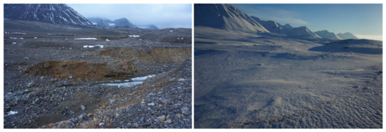 Figure 1. Two pictures, taken in October 2016 (left) and April 2017 (right), from the same location, illustrating the snowpack distribution over the moraine topography.
2. Study Site and Morphological Characteristics
This work was carried out on a small glacial basin that is located on the West coast of Spitsbergen (high-Arctic), on the North side of the Brøgger Peninsula (79 N, 12 E, Figure 2).
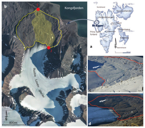
Figure 2.
General settings of the investigated area (a) with a focus (b) on Austre Lovén glacier basin. The proglacial moraine is delimited by the yellow line. The area where most of the hydrological and geomorphological processes occurred is in pale yellow, including the main water system, from the glacier outlet (red dot number 2) to the basin outlet (red dot number 1). (c) represents the moraine in spring at its snow maximum accumulation while (d) exhibits the snow free moraine in autumn. These two photos were taken from one of the highest point of the basin at app. 800 m.a.s.l. The red line on the oblique view images (c,d) matches the yellow line on the aerial photography (b), providing scale with respect to the orthorectified aerial picture.
With a km basin, Austre Lovén (AL) is a small land-terminating valley and polythermal glacier that covers an area of km , with a maximum altitude of no more than 550 m.a.s.l. AL exhibits a strong negative mass balance with a mean ablation rate of 0.43 m.a between 1962 and 1995, which increased to 0.70 m.a for the 1995–2009 period, as reported by [33]. Similarly to many small glaciers, AL is surrounded by rugged peaks and slopes that stand out against a flat forefield where surface run-offs are very dynamic [34]. Today, the moraine is a km large sedimentary complex that has formed since the Little Ice Age (LIA) period, which was around 1860 in this region. Hence, the moraine exhibits features that are representative of successive retreats of the glacier with a particular shape at the interface with the glacier snout, due to the fast retreat during the last decade [35]. The combination of glacier melting, temperature variability, and increasing precipitation [36] widely favors processes, such as sediment transfer [37], melting, and runoffs [38]. Under these dynamics, the proglacial moraine constantly reshapes from one year to another due to the glacial retreat exposing brittle material in a rough topography. With such a heterogeneous morphology coupled with a significant geomorphological and hydrological activity, the proglacial moraine is a key area. Indeed, several snowcover processes, such as melting processes [39,40] as well its role of water storage [41], play a key role in the broader source-to-sink dynamics.
3. Material and Methods
3.1. Reference Data
We designed our study on reference data on which our measurements are based and compared. The baseline Digital Elevation Model (DEM) used was obtained from ArcticDEM (https://www.pgc.umn.edu/data/arcticdem/ (accessed on 1 January 2021)). This model refers to 2015 images and provides a 2 m resolution DEM, which is accurate enough with respect to the natural (boulder) or size of the topographic features where artificial GCPs were located for UAV data referencing and validation.
The aerial images used as reference were provided by Norsk Polarinstitutt (available as a Web Map Tile Service (WMTS) service at http://geodata.npolar.no/arcgis/rest/services/Basisdata/NP_Ortofoto_Svalbard_WMTS_25833/MapServer/WMTS/1.0.0/WMTSCapabilities.xml (accessed on 1 January 2021)). The image that corresponds to the AL area was acquired in 2010 with a resolution of 16.5 cm, and it was well suited for ground control point localization. The overall definition and optical quality of the images were helpful in localizing and highlighting erratic boulders and terrain features that were used as the control points.
In addition to these data, the Topo Svalbard physical maps were also used as terrain references and implemented into the Geographical Information System software (Quantum Geographic Information System—QGIS available at https://qgis.org (accessed on 1 January 2021)) in this study. Figure 3 illustrates an overview of these reference data and highlights the focus on the region of interest.
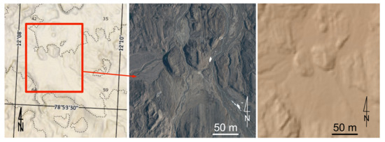
Figure 3.
Reference data, with (Left) the physical topographic map being used for basic controls and localization. (Center) reference orthophoto fetched on the WMTS server of Norsk Polar Institutt (acquired in 2010), cropped to the region of interest. (Right) associated DEM with a 2 m resolution.
3.2. Image Acquisition Protocol
Image acquisition was undertaken using a Commercial Off the Shelf (COTS) DJI Phantom 3 Professional UAV (Figure 4) that was fitted with its on-board camera based on the 1/2.3 CMOS, 12 Mpixel— pixel images—sensor exhibiting a field of view of 94, as would be obtained with a 20 mm equivalent lens on a 35 mm film. The UAV was used with its associated control hardware and software (DJI GO) while keeping the original settings, meaning that the camera was not calibrated. The flight elevation was set at approximately 110 m above ground level, providing a ground resolution of cm per pixel when considering the optical system lens properties. In total, 2795 pictures were collected in September 2016 during five successive flight sessions covering the whole moraine and glacier snout, and 1699 pictures were collected in April 2017 over two days.
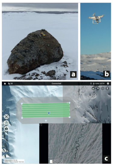
Figure 4.
Experimental setup: natural Ground Control Points are selected for their good visibility, even with the heavy spring snow cover. (a) Their position is measured using a dual-frequency GPS receiver, or identified on a reference orthophoto. (b) A COTS UAV is used for nadir picture acquisition from an elevation of 110 m above the take-off altitude. (c) Real time feedback of the camera view and GPS position of the UAV during acquisition improves safety and allows for adapting the flight path to features seen in the aerial views. Altizure software is used for setting the raster scan flight path accounting for horizontal speed, image coverage, and field of view.
Every camera parameters (ISO, shutter speed, and focal aperture) have been manually set, mainly depending on the light conditions as well as the ground nature (bare stones, ice, snow), as recommended in several works conducted in a similar environment [42,43,44].
Besides, a dedicated mapping software (Altizure, www.altizure.com (accessed on 1 January 2021)) was used to define raster-patterned flight plannings and storing such paths for later reproduction. Pre-defined flight plans and settings give a systematic approach that improves the efficiency and allows for a faithful repetition of the flight path, which is convenient for further data processing (photo overlap, triggering interval). Afterwards, these plans could also be used again in order to repeat the observations, ensuring a similar protocol of data acquisition. The overlap between pictures was set in the Altizure software to 80% in the fast scan flight direction and a sidelap of 60% in the slow-scan direction. Further details on this survey setup and validation were documented by [45].
For this work, data acquisitions were made in autumn (during the most likely snow-free moraine period, beginning of October) and spring (late April) at the theoretical peak snow accumulation. In autumn 2016, the UAV survey was flown during a single campaign to obtain both homogeneous images and a proper light pattern (i.e., no drop shadow and a sufficient light). In spring 2017, a two-day survey period was necessary because of the impact of cold weather on battery capacity. The total area that is covered by these surveys is c. 2 km , representing 88% of the total moraine surface. The investigation is split between a broad analysis of water storage volume computed through the snow cover thickness distribution, in addition to a focused investigation on the canyon and icings dynamics on a restricted 0.31 km region of interest (ROI), as described in Section 4.2.
Both of the periods present technical difficulties. In autumn, grazing sun and low lights imply careful camera settings (aperture, speed, and ISO choice) as well as short measurement intervals. The goal is to prevent the cast shadow from inducing an excessively variable observation of the same scenery during repeated passes of the UAV over the same region. In spring, the high reflectance, the lack of structures on the smooth snow cover, and low contrast also make photogrammetry challenging. Nevertheless, we observed protruding rocks or snow structures (i.e., sastrugis) to offer some usable tie points in most moraine areas (Figure 4).
The GCP coordinates were measured using a dual-frequency GPS receiver (Geo XH device with Zephyr antenna) and post-processed using RINEX data that were obtained from the EUREF Permanent Network station at Ny-Ålesund (http://www.epncb.oma.be/networkdata/ (accessed on 1 January 2021)), and their position and elevation were cross-checked with the ArcticDEM that was also used to assess the consistency of the resulting DSM.
The 2016 and 2017 imagery datasets were georeferenced using 25 GCPs. Twenty of them consisted of erratic boulders that were easily identified on an aerial picture, since they are, at least, bigger than 1 m . The other five GCPs consisted of pink plastic gardening saucers targets with a 30 cm diameter that were placed where no natural GCPs could be identified. They have not been permanently installed, and they have been deployed a few hours prior to the UAV flight each time. These saucers were also used as reference points.
Two parallel processing flows were run for independent assessment of the error sources:
- in autumn, dedicated GCPs were deployed in the moraine along the flight paths, and their position was recorded prior to the UAV flights. According to post processing, the accuracy obtained reached values of 15 cm for 98% of the markers, in the three directions (X, Y, Z);
- large boulders were identified on the Norsk Polar Institutt orthophoto used as reference and, thanks to the ArcticDEM, the three coordinates of these reference points are identified and used as GCPs in addition to positioning on the field using the dual-frequency GPS receiver.
3.3. Manual Snow Measurement
Unlike the glacier that exhibits a low-roughness surface, the moraine is characterized by a changing and, most of all, very rugged terrain. An avalanche snow probe was used to determine the snow depth in such a context and to ensure a reference measurements and then compare with DSM deduced snow cover thicknesses. This efficient way to quickly measure snow depth meets the objective of obtaining accurate values on a recurring basis. As reported by several works on snow science [46,47], it is the most common, easiest, and most reliable way of snow measurements protocol (especially when considering local scale works). Thus, to assess the quality of our data, 50 probings were carried out using a 3 m long snow probe with centimetric graduations during the same period that the UAV dataset was collected. A single operator made the campaign to avoid shifts in the way of probing along a transect following the central flowline. It extends over the glacier front to the maximum LIA glacier extent corresponding to hummocky moraine limits. Although probing values cannot be spatially interpolated due to the strong variability that is given by the uneven ground (which is one of the issues that initiated this work), these points provide a valuable one-off validation dataset that was compared with photogrammetric data.
3.4. Data Processing
In this study, we adopted the SfM workflow, as implemented in the commercial software package Agisoft PhotoScan Professional version 1.4.5. both for DSM and orthophoto generation. Its efficiency for such a purpose (i.e., geosciences and cold environments) was highlighted in several previous publications [48,49], and it represented a robust solution to achieve the goals that we had set up for this work. The detailed description of the SfM procedure using Photoscan is described in [50]: the classical steps for ground surface reconstruction have been followed according to a three-step process, as described and used by [51,52]. We used different photo chunks, in order to select regions of interest (ROI) in the moraine. More specifically for this work, we have chosen to edit several photos from spring acquisition. At this period, almost all of the ground is covered by snow, which gives a texture/colour consistency. This uniformity does not allow the registration algorithm to work properly unless some features, such as rocks or bare stones, can be found. To overcome this issue, we edited the photos with the Affinity Photo (version 1.8.4) software by using a batch processing, first increasing the contrast (slider at 50% of the available range) and then the sharpness (setting “70%”) with the “high pass sharpening tool”.
The generated data from Agisoft Photoscan were processed afterwards in QGIS open source software (LT version 2.8). The images were analyzed with the classical raster tools and the Object-Based Image Analysis (OBIA) to obtain surfaces of icings and a representation of the hydrological network.
In order to analyze the DSMs, we used the SAGA plugin that provides a robust toolbox for geosciences purposes, as described at sagatutorials.wordpress.com (accessed on 1 January 2021) whose “Terrain Analysis and Processing” and “Hydrological Flow Path” processing flowcharts were followed. In the SAGA toolbox, we first used the “terrain analysis → catchment area” tool to determine and apply the same catchment surface of comparison to both DSMs. Subsequently, the “morphometry” library allowed for correcting potential artefacts and closing gaps in the DSMs. Finally, the last step was completed with the “raster calculus → raster volume” tool to compute the differences between both of the DSMs (Difference of DSMs, DoD) and, hence, to estimate the volume of snow. These processing steps led to quantifying the remaining quantity of snow and the volume of melted snow and residual icing accretion. Processing the DSM differences over the whole moraine is challenging. Nevertheless, a raster difference layer was created by subtracting the 2016 (October) and 2017 (April) DSMs to assess snowpack accumulation over time. The entire area recorded was cropped to fit the area of interest. This area includes the outlet at the front of the glacier, following the main stream, up to the external moraine. This sequence represents the most rolling and changing topography.
4. Results and Discussion
4.1. Morphological Evidence of Icings Spatial Dynamics
The analysis of orthoimages shows significant differences with regard to icings size and distribution between the maximum snow accumulation and the end of the hydrological year (i.e., October to September of the next year) (Figure 5). Throughout recent years, in the moraine, we have observed firn areas getting smaller or even completely disappearing during the melting season. In this example, the surface of icings varies between a maximal extent of km to a residual extent of km at the very end of the hydrological season.
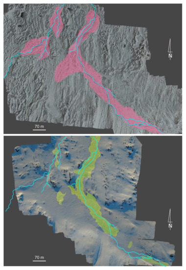
Figure 5.
Top: localization of the remaining hydrological network (light blue) coming from the melting season, and mapped on the ortho-image of October. These are the main channels where the major part of run-offs occurs. The pink areas exhibit the maximum extent of the icings at the beginning of the melting season. Bottom: the hydrological network (light blue) is overlapped on the ortho-image acquired in April, with the yellow areas highlighting the icings that are present at the time of acquisition.
The localization of remaining icing structures at the beginning and at the end of the season demonstrates the active water upwelling by capilarity through the snowpack as explained by [29]. Especially in the period of maximal snow accumulation, the processes are not fixed and a huge amount of liquid water flows into the snowpack depending on its quality (i.e., hard pack vs. fresh snow).
In autumn, the remaining icing areas are mainly located in the rugged part of the proglacial moraine where the impact of radiation is the lowest and the heavier cold katabatic air preferentially flows. In the case of the Austre Lovén basin, this means that icings are essentially located on the right bank (East side) of the proglacial moraine. These old canyons concentrate most on the firn accumulation that persists over a hydrological year. This situation contrasts with active periods, in spring. Icing field localizations correspond to the stream bed of the main outlet, but they include a large part of its floodplain. Indeed, these are areas where the snowpack is less thick: when combined with the action of strong pressure, the liquid water reaches the surface. This results in a wider area, which evolves very quickly from one day to another, as mentioned by [28]. This is a point that we observed on the field and that is actually impossible to map: UAV flight sessions should be carried out at least every half a day to highlight such dynamic changes. If we compare the images acquired in April 2017 with older data (satellite images from 2007–2009), icing fields today are less fragmented, but much wider when compared to previous year observations.
In the active area, i.e., the main proglacial river, the shapes of icings are more complex and elongated than in the inactive area. Moreover, while the inactive area exhibits residual icings, dynamics along the main rivers are more complex. During the melting season, the part of the icing spreading in the river channel usually melts completely. We observed that, in the proglacial moraine, flat proglacial zones favor the formation of larger icing fields. The snowpack seems to play a significant role in the development of icing mounds, as already described. The water that flows out of a glacier moves in and on the snowpack until upwelling by capilarity is stopped with sub-zero air temperatures. In the case of Autre Lovénbreen proglacial forefield, the compact structure of canyons as well as snow accumulation block the water that accumulates and flows out under pressure.
4.2. Data Quality Assessment: Snow Depth Calculation
We aim at determining the accuracy of remotely measured snow depth with respect to manually probing the snow cover thickness, which is considered to be the reference method. We applied a Bland and Altman test [53] on the reference values extracted from the manual probing transect and on the corresponding values that are to be tested and given by the DoD. The heterogeneity of the measurements is assessed thanks to the varied terrain crossed by the transect (from a rugged and complex topography to a flat smooth ground). The consistency of the results obtained by the two measurement methods—avalanche probe and DoD—is assessed with the estimate of the mean bias and standard deviation error between the two datasets. As described by [53], we calculated a confidence interval of 95%, which gives the Limits of Agreement (LoA), also derived as the mean value with the standard deviation.
The results of this test are reported in Figure 6, and they highlight excellent agreement with an average of less than 1 cm difference between the reference method (manual avalanche probing) and the tested method (photogrammetry and DoD) whenever the snow covers rocky areas and as long as icing fields are not crossed. All of the outliers (squared in yellow on Figure 6A) correspond to areas where icings dynamics occur (the red circles in Figure 6C) and from which the differences of measurements are associated with the presence of ice. However, the CD section, which is located on an icing free area, shows no shift and, thus, a significant convergence between both of the methods. Not removing these erroneous measurements point sets would raise the bias to cm and the LoA to 42 cm, which empahsizes the need to mask out icings when processing the data collected over the moraine to establish the snow cover water equivalent volume (Section 4.3).
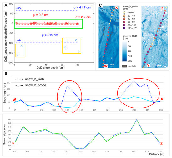
Figure 6.
Two cross sections (C) were selected for comparing DoD and manual avalanche probe measurement snow depths according to their geomorphological features as well as its dynamics: one section crosses icing areas (W,X) while the other is known to only include rock-covered areas (Y,Z). (B) displays the error between both of the measurement techniques as a function of snow depth, emphasizing the low error bar (less than 3 cm) and bias (less than 1 cm) between the measurements using the avalanche probe vs. DoD when eliminating the measurement over icings (red), while the bias (mean value as solid line) increases to cm and the Limit of Agreement (LoA, dashed lines) becomes equal to 1.96 times the standard deviation to nearly 42 cm (blue). (W,X) shows that the inconsistencies between the avalanche probe measurements and DoD only correspond to the icing areas that are filled with varying ice thickness, depending on the season. (A) highlights the Bland and Altman test that validates the consistency of the method used (i.e., difference of DSMs) with respect to a reference method (DoD).
In fact, the avalanche probe is unable to drill through such compact ice and, yet, the icings displaying melt in autumn will add to the DoD thickness measurement. Because icings are localized in the moraine to the riverbeds, their contribution to the total snow volume calculation will be negligible. The morphology of these steep-edged riverbeds makes them prone to be filled with snow, with the shapes forcing vertical capillary upwellings. On such morphological shapes, it is most likely that icing processes usually occur. The compact and hard snow/ice mixture does not allow the probe to reach the ground, which explains the difference of measured values, as depicted in Section 4.4.
The difference of DSMs applied to the snowpack thickness measurement emphasizes the importance of ground topography. Figure 7 highlights the smoothing effect (images below) when landforms exhibit very small topography. On the contrary, when the landforms are quite sharp (Figure 7, top images), even a strong wind effect is unable to smooth the surface. Indeed, a rugged topography promotes cornices formation. This is a much easier configuration for snow depth estimation, since:
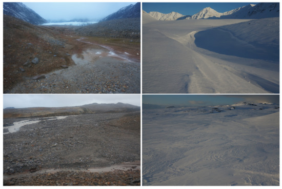
Figure 7.
Pictures taken from the same spot in April 2017 (right) and in September 2016 (left), towards the glacier (top) or the fjord (bottom), illustrating the smoothing effect of snow accumulation and hinting at the consistency of the observed ice and snow thicknesses that are quantitatively deduced from the difference of DSMs.
- the snowpack is in the range of a decimeter-to-meter deep and, hence, is easier to estimate by using photogrammetry; and,
- during the data processing step, cornices create shadows and structures that are identifiable by processing algorithm.
4.3. Water Equivalent Calculation
One of the main topics in studying a small glacial basin is to better understand the melting processes and their interaction with climate. Icing fields constitute a very important element of the cryosphere in the High Arctic, as they constitute a witness of thermal transformation of the glacier and, thus, indirectly on the impact of climate change, as was demonstrated [29].
Measuring the snow water equivalent (SWE) requires substantially more effort than only sampling the snow depth (HS). SWE and HS are known to be strongly correlated [54]. This correlation could potentially be used to estimate SWE from HS, even with few sampling points. Thus, studies have suggested enhancing the sampling efficiency by substituting a significant part of the time-consuming SWE measurements by simple HS measurements [55]. In our case, we carried out some snow sample measurements while flying the UAV, thus ensuring data acquisition at the same time. The snow samples were collected in snow pits at depths ranging from 20 to 100 cm by using 125 mL plastic bottles. Snow cover thickness was measured by using an avalanche probe following the same protocol as reported before. Despite varying snow conditions in various areas of the moraine, and depending on the surrounding topography yielding greater variable snow conditions than on the smooth glacier surface, the snow density was found to be homogeneous and constant at 0.43 ± 0.03 relative to water (1 g/cm ). This value is equal to those that are typically observed around the peninsula [56,57].
The snow depths deduced from DoD, as shown in Figure 8, are used for the water equivalent estimate over the whole moraine area. The mean snow thickness in the 2.2 km area of the internal moraine deduced from DoD is 333 mm, which, when multiplied by the snow density of 0.43, leads to 143 mm.SWE. This measurement excludes the hummocky moraine with its morphology that is characterized by a convex shape leading to rather snowy conditions. Our measurements on the 4.5 km glacier indicate a snow contribution of 491 mm.SWE. Hence, the snowpack contribution of the moraine accounts for % of the glacier contribution. Being normalized to the whole km basin, the moraine SWE contribution is mm. SWE, which compares to the glacier contribution of mm.SWE or a relative contribution of 14% that is normalized to the whole glacier basin. This statement should be balanced, since only the snowpack is included in this estimate while the groundwater and run-offs due to liquid precipitation are not taken into account in this calculation.
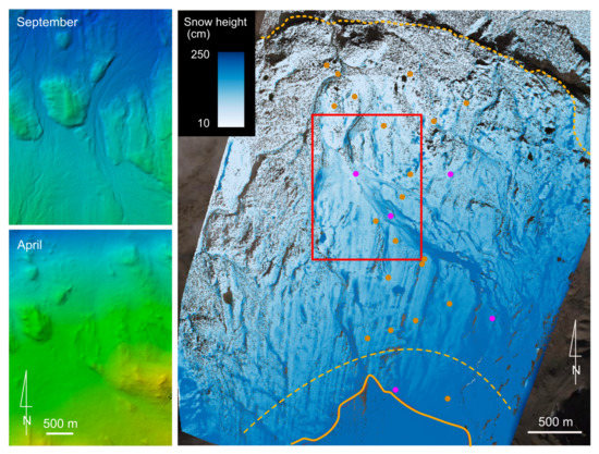
Figure 8.
DSMs were generated for both campaigns in October 2016 and April 2017. The spatial resolution was set at approximately 50 cm for both of the DSMs. The resulting difference of DSM is depicted on the right, with a threshold level at max. 250 cm. The yellow dotted line is the maximum extent of the moraine during LIA, the orange solid line is the current glacier front limit, and the dashed line corresponds to the limit of the new deglaciated area (i.e., during the last 10 years). The dots indicate the location of the GCPs, with red dots for natural GCPs consisting of large (>1 m) boulders, and pink dots for artificial GCPs located in flat areas. The red rectangle on the right image provides a geographical setting of the Region of Interest that is highlighted in both left images.
The error budget is as follows: because the SWE is deduced from a product of the density with the thickness h of the snow cover, the uncertainty on this quantity is
where indicates the uncertainty on quantity x. Here, mm mean snow cover height, so that the relative uncertainty according to the analysis of Figure 6, while the density uncertainty contributes to . Thus, both of the quantities contribute equally to a total uncertainty of 15% on the SWE.
These values emphasize the importance of the snowpack that is stored in the moraine in the hydrological equation of the watershed. This quantity of snow partly explains the increase of water runoffs at the melting season. The potential release of a massive amount of water increases the sediment transfer, as observed in [37]. This analysis solves one of the missing variables in the hydrological equation, including the glacier area, which is the moraine area here, as well as the still missing slope contribution to the global hydrological budget.
4.4. Lessons Learnt and Outlook
The use of SfM photogrammetry makes the estimation of snowpack characteristics is challenging. However, the measurements performed on the proglacial moraine assessed that there are strong snow drift effects. Regardless of snow accumulation, it appears that morainic mounds evolve very little, contrary to canyons, which are constantly re-shaping and subject to strong melting processes that consequently dig under sediment transport action. Thus, the structure of the topography promotes massive snow accumulation as well as the orthogonal orientation to the dominant winds. A lesson learnt while studying snowpack in the moraine is that the comparison with the glacier snowcover is possible with a low residual uncertainty, but it requires two workflows. Previous works [21,45] showed that, on the glacier, a simple interpolation can be applied to estimate both SWE and height. In the case of the proglacial moraine, the difference of DSM calculation is recommended since an interpolation is not consistent with its rugged topography. As often observed, the moraine constitutes a key area, but it is still hard to monitor. Based on this paper and previous works, the coupling of LiDAR measurements as references with several photogrammetric flight sessions appears to be the most efficient method.
UAV airborne data acquisition appears to be an efficient vector when addressing an investigation area of a few km with data collection lasting less than half a day, which meets the assumption of static measurement conditions. Photogrammetric SfM processing has then been used for generating DSM whose difference led to various geomorphological and snow cover evolution characterizations. When considering wider investigation areas, the uncertainty is more important and recent works that were carried out on the same area using RAdiofrequency Detection And Ranging (RADAR) lead to convincing results. However, the results given by RADAR are strongly correlated with the types of the snowpack: the presence of ice layers (due to rain on the snow event, far instance) decreases the accuracy of measurement due to the physical properties of RADAR signals and the complex interaction of electromagnetic waves with the snow pack. Thus, both of the methods seem to be complementary: the wide scale approach gives an overview, and data obtained through photogrammetry allow for surveying regions of interest. In addition, the use of a combined UAV campaign and photogrammetry processing is relevant in the context of phenomena occurring with an hourly to daily span with long lasting consequences, such as heavy snow fall, rainfall inducing canyon carving, and rain on snow events.
Discrepancies were highlighted between the manual measurements of snow depths and DoD analysis, which were interpreted, as illustrated in Figure 9, with the different quantities measured by both methods. The manual avalanche probe snow thickness is limited to the soft snow layer and it does not include the compact underlying ice of the icings. On the other hand, DoD integrates both quantities, since it refers to the ice-free moraine rocky surface observed in autumn. Beyond these icing areas, the snow cover thickness comparisons have been observed to match with a sub-decimeter accuracy, with DoD providing a high spatial resolution that cannot be matched with a manual avalanche probe measurement, which cannot be interpolated in the rough moraine area.
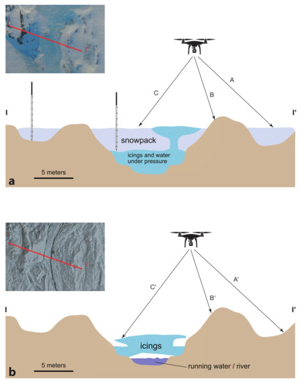
Figure 9.
Analysis of the different conditions that are met by subtracting DSMs collected when the snow cover is maximum (a) and has melted (b). A-A’ allows for snow cover thickness measurement, while B-B’ provides an estimate of the accuracy of the measurement by comparing snow-free areas where bare morainic rock is visible. Because of varying icings disposition, size, and volume between the beginning and end of the season, C-C’ being computed as the subtraction of one DSM to another does not yield the snow cover thickness. The scale on each cross-section schematic matches the length of the red line in the inset pictures. The avalanche probe schematic that is shown in the left of the top picture aims to illustrate how the snow cover thickness is measured over the rock-covered area, but how the measurement might be biased over icings with dense ice layers between the snow cover and bedrock, as is the case of SfM in the C-C’ condition.
Regarding icings dynamics, the seasonal approach that is described in this work will need to be extended to several years to better understand how climate influences its mechanisms. Nevertheless, inter-seasonal observation provided quite a few lessons. First, the presence or absence of icings indicates changes in the functioning of the proglacial moraine internal drainage system. Obviously, it appears that icings are not located in the same area in spring and in autumn. However, the important point is that, in autumn, there are no significant dynamics recorded, which is contrary to spring, where changes can be observed from one hour to another. The spatio-temporal scale at which processes are carried out is too fast to be measurable, even while using UAV surveys. It was quite easy to observe the fast formation of massive icing mounds, which raises questions regarding the icings dynamics. In autumn, the absence of any movement could be attributed to the fact that these icings are no longer in activity or supplied by water outflows. According to [58], this means that, in the case of Austre Lovén proglacial moraine, almost all of the icings are associated with rivers, glacial water outflows, and groundwater outflows. This conclusion is supported by spring observations, which clearly indicate the strong relationship between outflows and icings.
5. Conclusions
Two years of snow cover in an Arctic proglacial moraine area were investigated using the difference of Digital Elevation Models, referring to the snow-free dataset that was acquired in autumn. While spatial correlation is observed with respect to avalanche probe measurements in areas where snow accumulation over bare moraine rock is significant, the poor general correlation between in-situ measurement and remote-sensing techniques is attributed to the ice accumulation underlying the snowpack. This result is most striking in icings areas. The fine digital elevation model registration for snow cover thickness estimate requires ground-based control points. When lacking artificial reference points, natural ground control points were used here to register past and present acquisitions, referring to large boulders that are clearly visible, even at maximum snow cover, and that are known not to have moved in the last seven years with respect to the reference orthophoto. Despite the poor contrast under homogeneous snow cover conditions, Structure from Motion photogrammetric analysis appears to be suitable for mapping snow cover distribution, even in the low-lying sun cast shadow seen in Arctic environments.
Mapping the characteristics of a 2.4 km area proglacial moraine snow cover appears to be beyond the reach of a rotating wing quad-copter UAV: the estimate SWE for the whole moraine is not possible with the current dataset that was acquired over multiple flight sessions due to the limited (20 min. at most) autonomy. We conclude that a rotating wing UAV quadcopter is not suitable for such a large area. A fixed wing UAV seems to be a better suited solution, as demonstrated by [21], in which a 5 km tongue of a glacier was mapped, an area similar to the one under investigation here, through flights spanning about 0.35 km each, an area that is about 1.5 to two times larger than those covered during our rotating wing UAV flights. Despite similar flight elevation and adjacent image coverage, their flight duration at 2500 m.a.s.l. is approximately twice the one that we met in Arctic conditions of close to or sub-zero temperatures at sea level (15 min. flight durations for the DJI Phantom 3). In addition, combining SfM methods with satellite RADAR images analysis will open new opportunities for snowpack study in harsh conditions, as well as in a rough topographic environment, thanks to the high resolution DSM that is generated by the former technique needed for interferometric analysis of the latter. Despite the poorer RADAR spatial resolution (5 m for Sentinel 1) and high operating frequency (C-SAR at 5.4 GHz or a 5.5 cm wavelength) inducing a more complex interaction of the electromagnetic wave with the snow cover than an optical signal, such a technique [58,59] appears to be worth investigating with reference to a DSM generated by UAV.
Author Contributions
Conceptualization, É.B., J.-M.F. and M.G.; investigation, É.B., J.-M.F. and M.G.; writing—original draft preparation, É.B. and J.-M.F.; writing—review and editing, É.B. and J.-M.F.; funding acquisition, M.G. All authors have read and agreed to the published version of the manuscript.
Funding
This research was funded by Région Franche Comté grant and the logistic of French Polar Institute (IPEV).
Conflicts of Interest
The authors declare no conflict of interest. The funders had no role in the design of the study; in the collection, analyses, or interpretation of data; in the writing of the manuscript, or in the decision to publish the results.
References
- Nuth, C.; Moholdt, G.; Kohler, J.; Hagen, J.O.; Kääb, A. Svalbard glacier elevation changes and contribution to sea level rise. J. Geophys. Res. 2010, 115, F01008. [Google Scholar] [CrossRef]
- Hock, R. Glacier melt: A review of processes and their modelling. Prog. Phys. Geogr. 2005, 29, 362–391. [Google Scholar] [CrossRef]
- Lehning, M.; Ingo, V.; Gustafsson, D.; Nguyen, T.A.; St, M.; Zappa, M. ALPINE3D: A detailed model of mountain surface processes and its application to snow hydrology. Hydrol. Process. 2006, 20, 2111–2128. [Google Scholar] [CrossRef]
- Bernard, É.; Friedt, J.M.; Tolle, F.; Marlin, C.; Griselin, M. Using a small COTS UAV to quantify moraine dynamics induced by climate shift in Arctic environments. Int. J. Remote Sens. 2016, 1–15. [Google Scholar] [CrossRef]
- Tonkin, T.N.; Midgley, N.G.; Cook, S.J.; Graham, D.J. Ice-cored moraine degradation mapped and quantified using an unmanned aerial vehicle: A case study from a polythermal glacier in Svalbard. Geomorphology 2016, 258, 1–10. [Google Scholar] [CrossRef]
- Etzelmüller, B.; Ødegård, R.S.; Vatne, G.; Mysterud, R.S.; Tonning, T.; Sollid, J.L. Glacier characteristics and sediment transfer system of Longyearbreen and Larsbreen, western Spitsbergen. Nor. J. Geogr. 2010, 54, 37–41. [Google Scholar] [CrossRef]
- Martín-Español, A.; Navarro, F.; Otero, J.; Lapazaran, J.; Błaszczyk, M. Estimate of the total volume of Svalbard glaciers, and their potential contribution to sea-level rise, using new regionally based scaling relationships. J. Glaciol. 2015, 61, 29–41. [Google Scholar] [CrossRef]
- Derksen, C.; LeDrew, E. Variability and change in terrestrial snow cover: Data acquisition and links to the atmosphere. Prog. Phys. Geogr. 2000, 24, 469–498. [Google Scholar] [CrossRef]
- Barr, I.D.; Lovell, H. A review of topographic controls on moraine distribution. Geomorphology 2014, 226, 44–64. [Google Scholar] [CrossRef]
- Eckerstorfer, M.; Christiansen, H.H. Meteorology, Topography and Snowpack Conditions causing Two Extreme Mid-Winter Slush and Wet Slab Avalanche Periods in High Arctic Maritime Svalbard. Permafr. Periglac. Process. 2012, 23, 15–25. [Google Scholar] [CrossRef]
- Svendsen, H.; Beszczynska-Møller, A.; Hagen, J.O.; Lefauconnier, B.; Tverberg, V.; Gerland, S.; Ørbøk, J.B.; Bischof, K.; Papucci, C.; Zajaczkowski, M.; et al. The physical environment of Kongsfjorden–Krossfjorden, an Arctic fjord system in Svalbard. Polar Res. 2002, 21, 133–166. [Google Scholar] [CrossRef]
- Bednorz, E. Occurrence of winter air temperature extremes in Central Spitsbergen. Theor. Appl. Climatol. 2011, 106, 547–556. [Google Scholar] [CrossRef]
- Sobota, I. Icings and their role as an important element of the cryosphere in High Arctic glacier forefields. Bull. Geogr. Phys. Geogr. Ser. 2016, 10, 81–93. [Google Scholar] [CrossRef]
- Stumpf, A.; Malet, J.P.; Allemand, P.; Pierrot-Deseilligny, M.; Skupinski, G. Ground-based multi-view photogrammetry for the monitoring of landslide deformation and erosion. Geomorphology 2015, 231, 130–145. [Google Scholar] [CrossRef]
- Cook, K.L. An evaluation of the effectiveness of low-cost UAVs and structure from motion for geomorphic change detection. Geomorphology 2017, 278, 195–208. [Google Scholar] [CrossRef]
- Bhardwaj, A.; Sam, L.; Martín-Torres, F.J.; Kumar, R. UAVs as remote sensing platform in glaciology: Present applications and future prospects. Remote Sens. Environ. 2016, 175, 196–204. [Google Scholar] [CrossRef]
- Fonstad, M.A.; Dietrich, J.T.; Courville, B.C.; Jensen, J.L.; Carbonneau, P.E. Topographic structure from motion: A new development in photogrammetric measurement. Earth Surf. Process. Landforms 2013, 38, 421–430. [Google Scholar] [CrossRef]
- Lucieer, A.; Jong, S.M.D.; Turner, D. Mapping landslide displacements using Structure from Motion (SfM) and image correlation of multi-temporal UAV photography. Prog. Phys. Geogr. 2013, 38, 97–116. [Google Scholar] [CrossRef]
- Westoby, M.J.; Dunning, S.A.; Woodward, J.; Hein, A.S.; Marrero, S.M.; Winter, K.; Sugden, D.E. Instruments and methods: Sedimentological characterization of Antarctic moraines using uavs and Structure-from-Motion photogrammetry. J. Glaciol. 2015, 61, 1088–1102. [Google Scholar] [CrossRef]
- Nolan, M.; Larsen, C.; Sturm, M. Mapping snow depth from manned aircraft on landscape scales at centimeter resolution using structure-from-motion photogrammetry. Cryosphere 2015, 9, 1445–1463. [Google Scholar] [CrossRef]
- Gindraux, S.; Boesch, R.; Farinotti, D. Accuracy assessment of digital surface models from Unmanned Aerial Vehicles’ imagery on glaciers. Remote Sens. 2017, 9, 186. [Google Scholar] [CrossRef]
- Ryan, J.C.; Hubbard, A.L.; Box, J.E.; Todd, J.; Christoffersen, P.; Carr, J.R.; Holt, T.O.; Snooke, N. UAV photogrammetry and structure from motion to assess calving dynamics at Store Glacier, a large outlet draining the Greenland ice sheet. Cryosphere 2015, 9, 1–11. [Google Scholar] [CrossRef]
- Smith, M.W.; Carrivick, J.L.; Quincey, D.J. Structure from motion photogrammetry in physical geography. Prog. Phys. Geogr. 2015, 40, 247–275. [Google Scholar] [CrossRef]
- Eltner, A.; Kaiser, A.; Castillo, C.; Rock, G.; Neugirg, F.; Abellán, A. Image-based surface reconstruction in geomorphometry-merits, limits and developments. Earth Surf. Dyn. 2016, 4, 359–389. [Google Scholar] [CrossRef]
- Bernard, É.; Friedt, J.; Tolle, F.; Griselin, M.; Marlin, C.; Prokop, A. Investigating snowpack volumes and icing dynamics in the moraine of an Arctic catchment using UAV photogrammetry. Photogramm. Rec. 2017, 32. [Google Scholar] [CrossRef]
- Jagt, B.; Lucieer, A.; Wallace, L.; Turner, D.; Durand, M. Snow Depth Retrieval with UAS Using Photogrammetric Techniques. Geosciences 2015, 5, 264–285. [Google Scholar] [CrossRef]
- Bennett, G.L.; Evans, D.J.A. Glacier retreat and landform production on an overdeepened glacier foreland: The debris-charged glacial landsystem at Kvíárjökull, Iceland. Earth Surf. Process. Landf. 2012, 37, 1584–1602. [Google Scholar] [CrossRef]
- Bukowska-Jania, E.; Szafraniec, J. Distribution and morphometric characteristics of icing fields in Svalbard. Polar Res. 2005, 24, 41–53. [Google Scholar] [CrossRef]
- Bukowska-Jania, E. The role of glacier system in migration of calcium carbonate on Svalbard. Pol. Polar Res. 2007, 28, 137–155. [Google Scholar]
- Evans, D.J.A. Controlled moraines: Origins, characteristics and palaeoglaciological implications. Quat. Sci. Rev. 2009, 28, 183–208. [Google Scholar] [CrossRef]
- Rutter, N.; Hodson, A.; Irvine-Fynn, T.; Solås, M.K. Hydrology and hydrochemistry of a deglaciating high-Arctic catchment, Svalbard. J. Hydrol. 2011, 410, 39–50. [Google Scholar] [CrossRef]
- Lukas, S.; Nicholson, L.I.; Ross, F.H.; Humlum, O. Formation, meltout processes and landscape alteration if high-Arctic ice-cored moraines—Examples from Nordenskiöld Land, Central Spitsbergen. Polar Geogr. 2015, 29, 157–187. [Google Scholar] [CrossRef]
- Friedt, J.M.; Tolle, F.; Bernard, É.; Griselin, M.; Laffly, D.; Marlin, C. Assessing the relevance of digital elevation models to evaluate glacier mass balance: Application to Austre Lovénbreen (Spitsbergen, 79°N). Polar Rec. 2011, 48, 2–10. [Google Scholar] [CrossRef]
- Marlin, C.; Tolle, F.; Griselin, M.; Bernard, E.; Saintenoy, A.; Quenet, M.; Friedt, J.M. Change in geometry of a high Arctic glacier from 1948 to 2013 (Austre Lovénbreen, Svalbard). Geogr. Ann. Ser. Phys. Geogr. 2017, 99, 115–138. [Google Scholar] [CrossRef]
- Kohler, J.; James, T.D.; Murray, T.; Nuth, C.; Brandt, O.; Barrand, N.E.; Aas, H.F.; Luckman, A. Acceleration in thinning rate on western Svalbard glaciers. Geophys. Res. Lett. 2007, 34, L18502. [Google Scholar] [CrossRef]
- Hock, R.; Kootstra, D.S.; Reijmer, C. Deriving glacier mass balance from accumulation area ratio on Storglaciären, Sweden. Prog. Phys. Geogr. 2007, 1946, 163–170. [Google Scholar]
- Bernard, E.; Friedt, J.; Schiavone, S.; Tolle, F.; Griselin, M. Assessment of periglacial response to increased runoff: An Arctic hydrosystem bears witness. Land Degrad. Dev. 2018, 29, 1–12. [Google Scholar] [CrossRef]
- Hagen, J.O.; Eiken, T.; Kohler, J.; Melvold, K. Geometry changes on Svalbard glaciers: Mass-balance or dynamic response? Ann. Glaciol. 2005, 42, 255–261. [Google Scholar] [CrossRef]
- Bernard, É.; Florian, T.; Michel, F.J.; Christelle, M.; Madeleine, G. How short warm events disrupt snowcover dynamics Example of a polar basin—Spitsberg, 79°N. In ISSW Proceedings; IRSTEA: Grenoble, France, 2013. [Google Scholar]
- Ewertowski, M.W.; Tomczyk, A.M. Quantification of the ice-cored moraines’ short-term dynamics in the high-Arctic glaciers Ebbabreen and Ragnarbreen, Petuniabukta, Svalbard. Geomorphology 2015, 234, 211–227. [Google Scholar] [CrossRef]
- Wittmeier, H.E.; Bakke, J.; Vasskog, K.; Trachsel, M. Reconstructing Holocene glacier activity at Langfjordjøkelen, Arctic Norway, using multi-proxy fingerprinting of distal glacier-fed lake sediments. Quat. Sci. Rev. 2015, 114, 78–99. [Google Scholar] [CrossRef]
- Westoby, M.; Brasington, J.; Glasser, N.; Hambrey, M.; Reynolds, J. ‘Structure-from-Motion’ photogrammetry: A low-cost, effective tool for geoscience applications. Geomorphology 2012, 179, 300–314. [Google Scholar] [CrossRef]
- Lucieer, A.; Turner, D.; King, D.H.; Robinson, S.A. Using an Unmanned Aerial Vehicle (UAV) to capture micro-topography of Antarctic moss beds. Int. J. Appl. Earth Obs. Geoinf. 2014, 27, 53–62. [Google Scholar] [CrossRef]
- Colomina, I.; Molina, P. Unmanned aerial systems for photogrammetry and remote sensing: A review. ISPRS J. Photogramm. Remote Sens. 2014, 92, 79–97. [Google Scholar] [CrossRef]
- Bühler, Y.; Marty, M.; Egli, L.; Veitinger, J.; Jonas, T.; Thee, P.; Ginzler, C. Snow depth mapping in high-alpine catchments using digital photogrammetry. Cryosphere 2015, 9, 229–243. [Google Scholar] [CrossRef]
- Grünewald, T.; Schirmer, M.; Mott, R.; Lehning, M. Spatial and temporal variability of snow depth and SWE in a small mountain catchment. Cryosphere Discuss. 2010, 4, 1–30. [Google Scholar] [CrossRef]
- Bruland, O.; Sand, K. Snow Distribution at a High Arctic Site at Svalbard. Nord. Hydrol. 2001, 32, 1–12. [Google Scholar] [CrossRef]
- Cook, K.L.; Turowski, J.M.; Hovius, N. A demonstration of the importance of bedload transport for fluvial bedrock erosion and knickpoint propagation. Earth Surf. Process. Landf. 2013, 38, 683–695. [Google Scholar] [CrossRef]
- Harwin, S.; Lucieer, A.; Osborn, J. The impact of the calibration method on the accuracy of point clouds derived using unmanned aerial vehicle multi-view stereopsis. Remote Sens. 2015, 7, 11933–11953. [Google Scholar] [CrossRef]
- Verhoeven, G. Archaeological Three-dimensional Reconstructions from Aerial Photographs with PhotoScan. Archaeol. Prospect. 2011, 18, 67–73. [Google Scholar] [CrossRef]
- Dietrich, J.T. Riverscape mapping with helicopter-based Structure-from-Motion photogrammetry. Geomorphology 2016, 252, 144–157. [Google Scholar] [CrossRef]
- Uysal, M.; Toprak, A.S.; Polat, N. DEM generation with UAV Photogrammetry and accuracy analysis in Sahitler hill. Meas. J. Int. Meas. Confed. 2015, 73, 539–543. [Google Scholar] [CrossRef]
- Bland, J.M.; Altman, D.G. Statistical methods for assessing agreement between two methods of clinical measurement. Lancet 1986, 1, 307–310. [Google Scholar] [CrossRef]
- Deems, J.S.; Painter, T.H.; Finnegan, D.C. Lidar measurement of snow depth: A review. J. Glaciol. 2013, 59, 467–479. [Google Scholar] [CrossRef]
- Debeer, C.M.; Pomeroy, J.W. Modelling snow melt and snowcover depletion in a small alpine cirque, Canadian Rocky Mountains. Hydrol. Process. 2009, 2599, 2584–2599. [Google Scholar] [CrossRef]
- Obleitner, F. Measurement and simulation of snow and superimposed ice at the Kongsvegen glacier, Svalbard (Spitzbergen). J. Geophys. Res. 2004, 109, D04106. [Google Scholar] [CrossRef]
- Winther, J.G.; Bruland, O.; Sand, K.; Gerland, S.; Marechal, D.; Ivanov, B.; Gøowacki, P.; König, M. Snow research in Svalbard? An overview. Polar Res. 2003, 22, 125–144. [Google Scholar] [CrossRef]
- Dietz, A.J.; Kuenzer, C.; Gessner, U. Remote sensing of snow—A review of available methods. Int. J. Remote Sens. 2013, 33, 37–41. [Google Scholar] [CrossRef]
- Kääb, A.; Winsvold, S.H.; Altena, B.; Nuth, C.; Nagler, T.; Wuite, J. Glacier Remote Sensing Using Sentinel-2. Part I: Radiometric and Geometric Performance, and Application to Ice Velocity. Remote Sens. 2016, 8, 598. [Google Scholar] [CrossRef]


Publisher’s Note: MDPI stays neutral with regard to jurisdictional claims in published maps and institutional affiliations. |
© 2021 by the authors. Licensee MDPI, Basel, Switzerland. This article is an open access article distributed under the terms and conditions of the Creative Commons Attribution (CC BY) license (https://creativecommons.org/licenses/by/4.0/).