Abstract
Hybrid and quadrature-polarimetric (quad-pol) synthetic aperture radar (SAR) systems operating from space can obtain all polarimetric components simultaneously but suffer from severe azimuth ambiguities in the cross-polarized (cross-pol) measurement channels. In this paper, the hybrid and quad-pol SAR systems with multiple receive channels in azimuth are widely investigated to suppress the azimuth ambiguities of the cross-pol components. We first provide a more thorough analysis of the multichannel hybrid and quad-pol SAR systems. Then, the multichannel signal processing is briefly discussed for the reconstruction of the quad-pol SAR signal from the aliased signals, in which the conventional reconstruction algorithm causes extremely severe azimuth ambiguities. To this end, an improved reconstruction method is proposed based on a joint optimization, which allows for the minimization of ambiguities from the desired polarization and the simultaneous power of undesired polarized signal. This method can largely suppress azimuth ambiguities compared with the conventional reconstruction algorithm. Finally, to verify the advantages and effectiveness of the proposed approach, the azimuth ambiguity-to-signal ratio (AASR), the range ambiguity-to-signal ratio (RASR) and signal-to-noise ratio (SNR) of all polarizations, as well as a set of imaging simulation results, are given to describe the effects of reconstruction on the multichannel hybrid and quad-pol SAR systems.
1. Introduction
Quadrature polarimetric (quad-pol) synthetic aperture radar (SAR) systems play an important role in remote sensing. All polarimetric components, including co-polarized components and the cross-polarized components, can be obtained [1,2,3,4].
Hybrid or quad-pol SAR operates with the interleaved transmission of the alternate left (L)- and right (R)-circular polarizations or alternate (H+V) and (H-V) polarized pulses, receiving horizontal (H)- and vertical (V)- polarizations simultaneously after each transmission to build up a measurement of the complex scattering matrix formulated in a different polarimetric basis for each scattering target on the ground [5,6,7]. Besides this, the hybrid or quad-pol architecture leads to hardware that is more readily calibrated compared with the conventional quad-pol SAR system, because neither receiving channel is cross-polarized with respect to the transmitted polarization. Moreover, the hybrid or quad-pol architecture can significantly reduce the problem of rang ambiguities of cross-polarized (cross-pol) channels in a conventional quad-pol SAR system [7,8]. Therefore, the hybrid or quad-pol SAR has very promising advantages in the measurement of all polarizations.
In general, the hybrid or quad-pol SAR system cannot directly obtain all polarizations. Instead, it is required to transform the hybrid polarized data to polarimetric basis HH, HV, VH and VV by an additional mathematical transformation (linear combination operations, polarization synthesis). A key limitation to hybrid or the quad-pol SAR system has been the presence of first-order azimuth ambiguities of strong co-polarized (co-pol) (HH or VV) signals at the same time as the desired Doppler spectrum of relatively weak cross-pol (HV or VH) signals. In a hybrid or quad-pol SAR system, the hybrid polarimetric signals combines H and V polarizations. Additionally, there is a relative phase shift equal to in the polarizations in transmission. For example, in quad-pol SAR systems, V polarizations in the alternate (H+V) and (H-V) polarized signal are characterized by the opposite sign of , which leads to a Doppler frequency shift equal to half of the azimuth sample frequency [9], and thus results in the interplay of the odd-order azimuth ambiguities between the co-polarizations and cross-polarizations. Taking V polarized reception as an example, the VH and VV polarized signal in Doppler bin f can be expressed briefly as
where the represents the antenna pattern weighting ratio between the ambiguity and the desired signal. Therefore, the hybrid and quad-pol SAR systems both suffer from severe azimuth ambiguities in the cross-pol measurement channels [8].
The azimuth multichannel technique is a well-established technique allowing for mitigation of the contradiction between azimuth and range ambiguity in SAR systems. Moreover, the azimuth multichannel technique can also effectively reduce azimuth ambiguities without a pulse repetition frequency (PRF) increase for SAR systems. Therefore, we consider employing the azimuth multichannel technique [10,11,12,13,14,15,16,17,18] to the hybrid and quad-pol SAR systems to suppress the azimuth ambiguities of cross-pol channels.
In this paper, the hybrid and quad-pol SAR systems with multiple received channels are comprehensively investigated. Firstly, the multichannel hybrid and quad-pol SAR systems are mathematically described in vector format. The systems with multiple channels apply the conventional reconstruction algorithm, i.e., matrix inverse (MI) method [10], to retrieve the polarized signals. However, this method leads to extremely severe azimuth ambiguities for all polarizations, in which these azimuth ambiguities consist of two parts: one is from the azimuth ambiguity of the desired signal that can be ignored, and the other is induced by undesired polarizations, which is the main contribution of the azimuth ambiguities [19]. To this end, an improved reconstruction method is proposed based on a joint optimization, which allows for a minimization of azimuth ambiguities of the desired polarization and the power of undesired polarized signal with processing Doppler bandwidth simultaneously. Compared with the MI method, the azimuth ambiguities in cross-pol channels can be greatly suppressed by the proposed method.
This paper is organized as follows. In Section 2, we first provide a thorough analysis for the multichannel hybrid and quad-pol SAR systems. Then, the conventional matrix inverse (MI) method for reconstructing multichannel polarized signal is introduced. An improved reconstruction method based on a joint optimization is proposed to suppress the azimuth ambiguities at the end of Section 2. The analytical results, based on the azimuth ambiguity-to-signal ratio (AASR), the range ambiguity-to-signal ratio (RASR) and signal-to-noise ratio (SNR) of all polarizations, are given in Section 3 to describe the effects of reconstruction on the multichannel hybrid and quad-pol SAR systems. In Section 3, imaging simulations as well as numerical simulation results are also demonstrated, showing the advantage and effectiveness of the proposed approach. Finally, conclusions and some more discussions are drawn in Section 4.
2. Materials and Methods
2.1. Multichannel Hybrid and Quad-Pol SAR Systems
From [8], it can easily be obtained that the multichannel hybrid and multichannel quad-pol SAR systems lead to similar derivations. Thus, without loss of generality, we only discuss the multichannel quad-pol SAR system in the following. In this section, signal models are briefly introduced to describe the properties of multichannel quad-pol SAR systems. One can observe that the signal model of the desired polarized signal is the same as that of the conventional multichannel SAR system, while the undesired polarized signal possesses a distinctive form.
2.1.1. Multichannel Quad-Pol SAR
Figure 1 shows the geometry of a multichannel quad-pol SAR system, in which the receivers are uniformly equipped with M sub-antennas along the azimuth direction. The length of the sub-antennas and the distance of the phase center between adjacent antennas are both d.
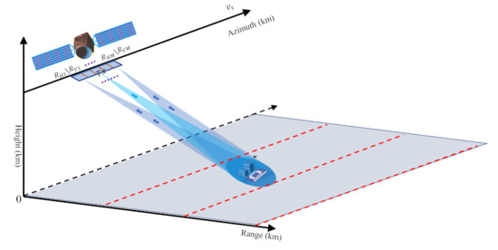
Figure 1.
Geometry of the multichannel quad-pol SAR system.
First, let the polarized signals from the receivers and be the reference channel signals of the H and V reception, respectively. Then, according to the geometry shown in Figure 1, the polarized echo received by the ith channel () can be approximately derived as
where denotes the impulse response of reference channel for each polarized signal, is the platform velocity, is the wavelength, is the minimal slant range between the azimuth direction and the scatter, and . The exponential term in (2) is a constant phase and can be pre-compensated before signal reconstruction processing. Therefore, this exponential term is ignored for convenience in the following discussion.
Figure 2 shows the spatial distribution of samples in azimuth direction from four transmit pulses separated by for a three-channel quad-pol SAR system (as an example), in which the circles represent equivalent phase centres, is the time distance between two transmitted pulses with the same polarization, and the time distance between two successive pulses is accordingly. According to the received polarization sequences (see Figure 2), the sampled polarization signals for the the multichannel quad-pol SAR system can be written as products of corresponding continuous azimuth polarization signals and Dirac combs [20] as follows:

Figure 2.
Spatial distribution of samples in azimuth direction from four transmit pulses separated by for a three-channel quad-pol SAR systems. The circles represent equivalent phase centers separated by .
The above equation shows that the expressions of the polarized signals from H reception are similar to that of the polarized signals from V reception. Therefore, this section chooses polarized signals from V reception for analysis.
According to Fourier transformation, the spectra of the polarized signals from V reception can be written by
where , and denotes the channel function, given by
According to Equation (4), the spectra in vector formal can be formulated as
and
where the VH-polarized signal in vector format is given by
and the VV-polarized signal in vector format is given by
The matrix represents the channel matrix given by
and represents the channel vector given by
The matrix depends on the
where denotes a diagonal matrix whose diagonal elements are the components of a vector .
Therefore, the spectra of the sampled received signal from V reception in vector format can accordingly be written as
where represents the spectrum of V-reception signal, and denotes noise vector and denotes the matrix transpose operator. Then, the signal covariance of desired polarization corresponding to the multichannel output in Doppler bin f is given by
Similarly, the signal covariance of undesired polarization is given by
where denotes the statistical expectation, and denotes the matrix conjugate transpose operator. In the case of SAR imaging, the covariance matrices and can be reformulated as [13]
and
where and represent the signal power of the desired and undesired polarization signal, respectively; and depends on the two-way antenna pattern , which is given by
Generally speaking, the two-way antenna pattern can be approximated as a function of (see Figure 3).

Figure 3.
The two-way antenna pattern .
2.1.2. Sampling Frequency (PRF)
A few considerations regarding the PRF and its relationship to the antenna spacing d are in order. Reference [13] defines a specific set of PRFs given by
When using PRFs from this set, the channel vector is periodic, with a period of K
As a result, the number of degrees of freedom (DOFs) K available to reconstruct the signal is lower than available Rx channels M. When K equals the number of channels M, the uniform PRF can accordingly be defined as
Then, the nonuniform PRFs are between the uniform PRF and specific PRFs .
2.2. Reconstruction Methods for Multichannel Quad-Pol SAR
2.2.1. Conventional Matrix Inversion (MI) Method
The matrix inverse (MI) method is based on the work in [10]. Without loss of generosity, the number of channels M is assumed to be an odd number. Then, let be reconstruction filters to reconstruct the desired polarization Doppler spectra from aliased signals. Let be an channel matrix given by
Then, the set of filters used to retrieve the desired polarization signal is obtained by computing the inverse matrix of , given by
where is an vector of zeros except for the element, which is equal to one.
In general, the MI method allows for the unambiguous recovery of the band-limited Doppler spectrum for multichannel SAR systems. However, the MI method mainly aims to suppress the azimuth ambiguities of the desired polarization signal. In contrast, the undesired polarization signal still exists in the multichannel quad-pol SAR systems and the desired polarization channel suffers from extremely severe azimuth ambiguities.
2.2.2. Joint Optimization to Suppress the Ambiguity (JOSA)
As mentioned above, the MI aims to suppress the azimuth ambiguities of the desired polarization signal but ignores the suppression of the undesired polarization signal. The undesired polarization signal causes more severe ambiguities than that from the desired polarization signal after reconstruction filters for the multichannel quad-pol SAR systems.
To this end, consider using a joint optimization to suppress the ambiguities. Specifically, through the reconstruction filter (), the spectra estimation of VH-polarized signal can be obtained as
where the first term of the right side of Equation (24) denotes the reconstructed VH-polarized signal, the second term denotes the azimuth ambiguity from VH-polarized signal, the third term represents the ambiguity induced by undesired VV-polarized signal and the fourth term is noise.
According to (24), the azimuth ambiguity power of the desired VH polarization can be derived by
where the represents the total power from the desired VH polarization, which can be derived by (16) after reconstruction filter . Note that the desired VH polarized signal is exactly the first term in (24), which is reconstructed as , whereas the azimuth ambiguities from the desired VH polarization are not properly reconstructed through filter as .
Similarly, the ambiguity power induced by undesired VV-polarized signal can be derived from (17):
Therefore, to largely suppress the ambiguity of the multichannel hybrid quad-pol SAR systems, a joint optimization is established to minimize the ambiguity power and simultaneously, which is given by
Using the Lagrange multiplier method [21,22], the corresponding solution of the joint optimization can accordingly be obtained as
One may note from equation (12) that the matrix is a periodic matrix with respect to with period . When and n is an integer, the matrix is transformed to an identity matrix. In this case, the factor in (28) becomes
Additionally, according to the definition of sampling frequency in (19), when , the matrix becomes singular, and thus the matrix is accordingly a singular matrix. Compared with the special PRFs, this can also be written as
Thus, the whole pulse repetition frequency between two successive pulses is lager than the . Then, due to the fact that the matrix with respect to is not invertible, one may calculate the Moore–Penrose generalized inverse matrix of this matrix to obtain the reconstruction filters.
3. Results
To characterize the effect on the hybrid and quad-pol SAR signals of the application of the azimuth multichannel technique and the multichannel performance, three parameters should be discussed:
- (1)
- AASR for different polarizations after reconstruction;
- (2)
- RASR for different polarizations after reconstruction;
- (3)
- Output signal-to-noise ratio (SNR) for different polarizations.
3.1. Characterization of the Reconstruction and Performance
3.1.1. Effects of Reconstruction on Azimuth Ambiguity
As mentioned in the previous section, the azimuth ambiguities consist of the azimuth ambiguity of the desired (VH) polarization and the ambiguity induced by undesired (VV) polarization signals. Let be the reconstruction filter of polarization. Then, through the Equations (25) and (26), one can obtain the AASRs of different polarization signals for the multichannel quad-pol SAR.
Due to the fact that only a constant phase difference between hybrid and quad-pol modes [7,8], the multichannel hybrid quad-pol SAR has the same mathematical expressions of AASR as (31).
3.1.2. Effects of Reconstruction on Range Ambiguity
Range ambiguities arise from preceding and succeeding echoes arriving back at the radar simultaneously with the desired return [23]. In the multichannel quad-pol system, the ambiguous range of echoes from even and odd pulses correspond to radiated pulses with different polarizations.
Let and be the odd-order and even-order range ambiguities received by the channel of V reception, respectively. Similar to the derivation process of polarization signal model for the multichannel quad-pol SAR (see Equations (6), (7) and (13) in Section 2.1.1), the spectra of sampled odd-ambiguous signal from V reception in vector format can accordingly be written by
where represents the vector format of odd-order range ambiguous signals ; , represent the Doppler spectra of the odd-ambiguous signals from different polarizations (VH and VV from V reception) and their mathematical expressions are similar to the Equations (8) and (9) :
Then, similarly, the Doppler spectra of the sampled even-ambiguous signal can also be written by
where represents the vector format of even-order range ambiguous signals ; , and represent even-ambiguous signals from different polarizations:
Note that in (32) and (34), the constant coefficients of VV polarization are and , respectively. This is due to the interleaved transmission of alternate (VH+VV) polarization and (VH-VV) polarization in quad-pol SAR systems (see Figure 2).
The power of range ambiguous signal in Doppler bin f after reconstruction filter can accordingly be obtained as
where is the look angle of the n-order range ambiguous area, is the number of range ambiguities, and represent the backscatter reflectivity of VH and VV polarization, respectively, is the two-way antenna power pattern in elevation, and is the slant range of the n-order range ambiguous area. Besides this, one can notice that the first term of the right side of (36) denotes the range ambiguity of desired polarization, and the second term denotes the range ambiguity induced by undesired polarization.
According to Equation (25), the power of desired polarization signal can be derived as
where is the look angle of the desired area and is the slant range of the desired area.
Thus, the range ambiguity-to-signal ratio (RASR) in Doppler bin f can accordingly be written by
The expression is Doppler frequency related. From (38), one can observe that the RASR consists of two components: the first one is completely irrelevant to reconstruction, while the other is directly decided by the reconstruction filter. The first term in (38) is a constant as the frequency-related coefficients in (36) and (37) cancel each other, whereas the second term relies on the reconstruction filter .
If the undesired VV polarization power is much larger than that of the desired VH polarization after reconstruction, the VH-polarized signal will suffer from severe range ambiguity. Therefore, it is of significance to design agreeable reconstruction filters to ensure the requirement of RASR in the multichannel hybrid and SAR systems. To this end, an optimization problem to minimize the RASR can be established as
Then, to solve this problem, the optimization can be transformed as
In general, due to the constraint , the term can be an approximate constant, and one can obtain a similar optimization problem as (see (27)). Therefore, the solution to the joint optimization can be treated as the optimal solution of the optimization . That is, the JOSA method can also achieve almost the lowest RASR.
According to Equation (38), one can obtain the whole RASR expressions (see (41)) of different polarizations for the multichannel hybrid and quad-pol SAR systems. As shown in (41), one can note that the RASR consists of two components: the first term represents the desired RASR, and the second term includes undesired RASR and the ratio of undesired azimuth signal power and desired azimuth signal power (UDR). Generally speaking, one can note that the UDR is approximately the AASR according to the Equation (31).
3.2. Numerical Simulation Results of Reconstruction Methods
In this section, the reconstruction performance of the proposed method (JOSA) is investigated for the exemplary multichannel quad-pol SAR systems defined in Table 1.

Table 1.
System Parameters.
As a comparison, the performance of the quad-pol SAR system is first briefly introduced. Then, this section discusses the reconstruction performance of all polarizations by the MI and JOSA methods for the multichannel quad-pol SAR system. The PRF is restricted to the interval between 760 Hz and 2600 Hz. One may note that this PRF denotes the PRF of two successive pulses. For performance analysis, three systems (see systems #1, #2 and #3 in Table 1) are considered to evaluate the behavior of the proposed method versus the PRF.
Figure 4 shows the configurations of these three systems, in which system #1 and system #2 have the same Rx antenna length but different Doppler bandwidths, and system #1 and system #3 possess the same Doppler bandwidth but with different Rx antenna lengths. System #1 is used for the quad-pol SAR, while systems #2 and #3 represent the multichannel quad-pol SAR systems with different Rx antenna lengths.
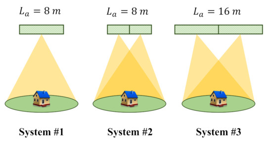
Figure 4.
Diagrams of systems #1, #2 and #3. Systems #1 and #2 have the same length of Rx antenna, while systems #2 and #3 have the same number of channels.
Figure 5 shows the two-way antenna patterns of these three systems. As shown in Figure 5, systems#1 and #3 have the same azimuth patten, while system #2 possesses a distinctive azimuth pattern.

Figure 5.
Configuration of systems #1, #2 and #3. Systems #1 and #2 have the same length of Rx antenna, while systems #2 and #3 have the same number of channels.
3.2.1. ASRs Performance of Single-Channel Quad-Pol SAR System (System #1)
For comparison, the AASR and RASR performance of quad-pol SAR system (system #1) is first depicted in Figure 6. Figure 6a shows the AASR performance of all polarizations versus PRF. It can be observed that the AASR of cross-pol signals of quad-pol SAR system is beyond −18 dB . The RASR performance (PRF = 3756 Hz) of quad-pol SAR system versus the ground range is shown in Figure 6b, in which all the RASR values are lower than −20 dB.

Figure 6.
AASR and RASR performance of quad-pol SAR system (system #1). (a) AASR versus PRF; (b) RASR (PRF = 3756 Hz) versus the ground range.
In general, the quad-pol SAR system requires PRF to eliminate the alias of the undesired signal. However, as the backscatter for the cross-pol channels is usually much lower than that for the co-pol channels, the cross-pol channels suffer from severe azimuth ambiguity even if PRF . For example, in Figure 6a, the AASR of HV and VH polarizations is about −7 dB when PRF = 3756 Hz. Though the AASR of cross-pol channels decreases with the increased PRF, the AASR is still beyond −20 dB and this result cannot satisfy the requirement of the SAR system.
3.2.2. ASRs Performance of Multichannel Quad-Pol SAR System (Systems #2 & #3)
Therefore, we consider the use of the multichannel technique to suppress the azimuth ambiguity. For the above multichannel systems #2 and #3, here are the ASRs performance results after reconstruction by conventional MI method and the proposed JOSA method, from Figure 7, Figure 8, Figure 9 and Figure 10. ASRs equations of all the four linear polarizations (HH/HV/VH/VV) of multichannel quad-pol SAR system after reconstruction are derived in Section 3.1, AASR (31) and RASR (41).

Figure 7.
AASR and RASR performance of system #2 by MI method. (a) the AASR versus PRF; (b) the RASR (PRF = 3756 Hz) versus the ground range.

Figure 8.
AASR and RASR performance of system #2 by JOSA method. (a) the AASR versus PRF. (b) the RASR (PRF = 3756 Hz) versus the ground range.

Figure 9.
AASR and RASR performance of system #3 by MI method. (a) the AASR versus PRF. (b) the RASR (PRF = 3756 Hz) versus the ground range.

Figure 10.
AASR and RASR performance of system #3 by JOSA method. (a) the AASR versus PRF. (b) the RASR (PRF = 3756 Hz) versus the ground range.
Figure 7 and Figure 9 show the AASR and RASR performance curves of systems #2 and #3 by conventional MI method. Figure 7a and Figure 9a demonstrate the AASR performance of systems #2 and #3, respectively. One can observe that almost all the AASR values of cross-pol signals (HV and VH) are beyond −20 dB. Moreover, both systems #2 and #3 suffer from extremely severe azimuth ambiguities when the PRF is close to the special PRF (see Equation (19), located at the peak positions in Figure 7a and Figure 9a.
The RASRs of these two systems versus the ground range for PRF = 3756 Hz are depicted in Figure 7b and Figure 9b, respectively.
As system #2 has very high UDR due to the high AASR value when PRF=3756 Hz (the corresponding special PRF is 3796Hz), one can notice that system #2 suffers from severe range ambiguities (see the second term of the right side of the Equation (41)). In Figure 9, though the cross-pol signals of the system #3 also have high AASR value, it does not cause too many effects on all the RASR because the UDR is lower than dB (see the AASR value, which can be approximated as the UDR value, see (31) and (41)), and the RASR is very close to the desired value. In a word, the MI method leads to poor AASR and RASR performance in multichannel quad-pol SAR.
To improve the ASRs performance of all polarizations, a novel method based on joint optimization (JOSA) is employed to system #2 and system #3. Figure 8 and Figure 10 show the AASR and RASR performance of systems #2 and #3 by the JOSA reconstruction method.
Compared with the MI method, the JOSA method can largely improve the AASR and RASR performance of all polarizations. For system #2, the AASR is below dB when PRF is within 3475 Hz and 4597 Hz with JOSA method applied (see Figure 8a, comparing with Figure 7a). For system #3, the AASR is below dB when PRF is beyond 4557 Hz (see Figure 10a, compared with Figure 9a).
Though the JOSA method can achieve low AASR for the system #3, this system requires higher PRF (beyond 4557 Hz), which would lead to degraded RASR performance. Compared with system #3, system #2 can obtain a low AASR value using the JOSA method with lower PRF (within 3475 Hz and 4597 Hz). As shown in Figure 8b and Figure 10b, the JOSA method can achieve a very low RASR (below dB) for system #2 and system #3. Note that system #3 here is a reference group. For the multichannel hybrid or quad-pol SAR of system #3, the corresponding special PRF is 5706Hz, which could be unusually large for a spaceborne SAR system (even the PRF of 4557 Hz in Figure 10a is relatively large). Thus, like other conventional azimuth multichannel systems [10], an appropriate beam position design is required in advance.
To further compare the MI method and JOSA method, Table 2 and Table 3 summarize the AASR performance of different methods with PRF = 3756 Hz and PRF = 3502 Hz for different systems, respectively.
Table 2.
AASR Performance (PRF = 3756 Hz).
Table 3.
AASR Performance (PRF = 3502 Hz).
From Table 2 and Table 3, we can see that the cross-pol signals of system #2 reconstructed by the proposed JOSA method have the lowest AASR when PRF = 3756 Hz and PRF = 3502 Hz. Compared with the conventional MI method (the third column), the AASR results of the four linear polarizations (HH/HV/VH/VV) achieve equilibrium in system #2 with the JOSA method applied (the fourth column). The AASR performance of all the polarizations is lower than dB. Note that the same PRF values are used in simulations of system #3. However, despite this, the cross-pol signals reconstructed by the JOSA method have lower AASR values than the cross-pol signals reconstructed by the conventional MI method.
In a word, the azimuth multichannel technique with JOSA method can improve the AASR performance of hybrid or quad-pol SAR system.
3.2.3. Imaging Simulation Results
To be more intuitive, this section gives a set of imaging simulations based on SAR systems #1 and #2 using parameters listed in Table 1. A set of nine points are simulated, see Figure 11 and Figure 12.
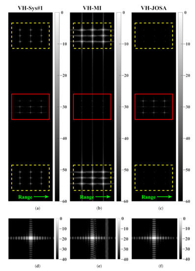
Figure 11.
Multi-point imaging results of VH polarization with azimuth ambiguities considered (nine points). System parameters in Table 1 is applied. Amplitude of all the sub-figures is normalized in dB. (a) Multi-point simulation result of VH polarization based on system #1 (single-channel quad-pol SAR); (b) points simulation result of VH polarization based on system #2 (multichannel quad-pol SAR), reconstructed via the conventional MI method; (c) points simulation result of VH polarization based on system #2 (multichannel quad-pol SAR), reconstructed via the proposed JOSA method. Points marked with solid red rectangle in (a–c) represent the desired targets, while the points in yellow dashed rectangle represent the fake targets introduced by ambiguities. (d–f) give the up-sampled imaging results of the desired targets (points in the upper-left corner) in (a–c), respectively.
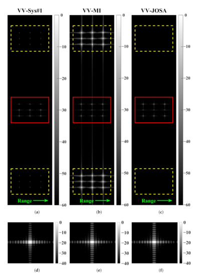
Figure 12.
Multi-point imaging results of VV polarization with azimuth ambiguities considered (nine points). System parameters in Table 1 are applied. Amplitude of all the sub-figures is normalized in dB. (a) Multi-point simulation result of VV polarization based on system #1 (single-channel quad-pol SAR); (b) points simulation result of VV polarization based on system #2 (multichannel quad-pol SAR), reconstructed via the conventional MI method; (c) points simulation result of VV polarization based on system #2 (multichannel quad-pol SAR), reconstructed via the proposed JOSA method. Points marked with red solid rectangle in (a–c) represent the desired targets, while the points in yellow dashed rectangle represent the fake targets induced by ambiguities. (d–f) give the up-sampled imaging results of the desired targets (points in the upper-left corner) in (a–c), respectively.
Figure 11 and Figure 12 show the VH and VV polarimetric imaging results, respectively. Similarly, imaging results of system #1 (normal single-channel quad-pol SAR) are first presented for comparison as Figure 11a and Figure 12a (the first column). In Figure 11 and Figure 12, sub-figures of (b) (Figure 11b and Figure 12b) and (c) (Figure 11c and Figure 12c) show the imaging results of system #2 reconstructed by the conventional MI method and the proposed JOSA method.
Additionally, point targets in the figures are separated: the desired targets (marked with red solid rectangle) and the fake targets induced by azimuth ambiguities (marked with yellow dashed rectangle). Moreover, the upper-left desired point targets in Figure 11 and Figure 12 are up-sampled, displaying the reconstruction results; see sub-figures of (d–f) (Figure 11d–f and Figure 12d–f).
Take VH polarization (Figure 11) as an example. As can be seen in Figure 11a, the power of the fake targets induced by azimuth ambiguities is strong, even if there is a little bit of defocus. This is because the co-polarization (VV) is the key contributor to the ambiguities in hybrid or quad-pol SAR systems [7,8].
From Figure 11b, we can see that the imaging performance after reconstruction is poor through the conventional MI reconstruction method. Specifically, in the up-sampling result of Figure 11e, the desired point target has been greatly contaminated by the ambiguities. Through the MI method, the AASR performance of all the four linear polarizations deteriorates (see Figure 7 and Table 2).
On the contrary, with the application of the proposed JOSA method, Figure 11c gives a decent imaging result of the cross-polarization (VH) compared to both the result of the common single-channel mode (Figure 11a) and the result reconstructed by the MI method (Figure 11b). In Figure 11c, the power of the fake targets induced by azimuth ambiguities degrades significantly. In addition, for VV polarization in Figure 12, imaging performance after reconstruction by the JOSA method is even better, of which the fake targets marked in yellow dashed rectangle are barely visible; see Figure 12c. This phenomenon further validates the feasibility and effectiveness of the proposed JOSA method.
The numerical result is also listed in Table 4. The data in Table 4 were obtained by calculating the ratio of the azimuth ambiguous target and the desired target considering the point impulse response [24]. Note that these ratio values in dB do not represent the AASR performance exactly. Specifically, since the azimuth ambiguous target is defocused, data in Table 4 are lower than the actual AASR values with only the maximum amplitude value considered.
Table 4.
Amplitude Intensity Ratio of Point Impulse Response.
Observing and comparing the ratio values in the same column in Table 4, it can be found that the intensity disparity of azimuth ambiguities from VH and from VV polarizations matches the AASR curves (from Figure 6, Figure 7 and Figure 8). For example, with the MI reconstruction method, the impulse response of the VV polarized target in Figure 12b is stronger than that of the VH-polarized target in Figure 11b. This means the relative strength of the azimuth ambiguities in VH polarization is larger. In Table 4, the difference in the ratio values of VH and VV polarizations by the MI method is dB, which leads to a poor imaging result, as shown in Figure 11e.
3.3. Effects of Reconstruction on Noise
As can be seen in Equation (24), it contains a noise component, which could also affect the reconstruction performance in multichannel systems. Based on the joint optimization result, the SNR for different polarizations can be then defined as (42)
Figure 13 and Figure 14 show the SNR performance result of systems #2 and #3 based on the conventional MI reconstruction method and the proposed JOSA method.

Figure 13.
SNR performance curves of system #2 after reconstruction (a) via conventional MI method; (b) via the proposed JOSA method.

Figure 14.
SNR performance curves of system #3 after reconstruction (a) via conventional MI method; (b) via the proposed JOSA method.
The SNRs of systems #2 and #3 versus PRF with the MI method are shown in Figure 13a and Figure 14a. Both systems suffer from severe noise when the PRF is close to the special PRF as the MI method is used. In sum, the MI method leads to poor AASR, RASR and SNR performance.
While from Figure 13b and Figure 14b, which show the SNRs of systems #2 and #3 versus PRF with the proposed JOSA method, one can observe that the system #2 possesses high SNR for all PRFs, the system #3 only has low SNR when the PRF is close to 3756 Hz. This proves the better performance of the proposed JOSA method over the conventional MI method.
4. Conclusions
In this paper, we discuss the ambiguity performance of the hybrid and quad-pol SAR systems with multiple received channels. Through the conventional matrix inverse (MI) reconstruction algorithm, the ambiguity performance is unsatisfactory. This is because, in addition to the ambiguity of the desired signals, it also contains ambiguity from undesired polarizations, which is the main contribution of the azimuth ambiguities. Therefore, we introduce an improved reconstruction method based on joint optimization (JOSA) to minimize the ambiguities.
Two parts are considered: the original ambiguities from desired polarizations (VH or HV), and the ambiguities induced by undesired polarizations (VV or HH). Through numerical analyses, as well as simulations of ASR curves and multi-point imaging results, the effectiveness of the proposed JOSA method is verified. The SNR performance results of the MI method and the proposed JOSA method presented in the latter also prove the superiority of the JOSA method in terms of ambiguity suppression and signal quality in hybrid or quad-pol SAR systems.
Additionally, for multichannel SAR systems, the system stability enhancement is also of importance. In future research, other systematic errors such as the channel imbalance could be taken into further consideration for robustness analysis.
Author Contributions
Conceptualization, P.Z.; methodology, P.Z. and Y.Z.; validation, P.Z. and Y.Z.; formal analysis, P.Z.; investigation, P.Z.; resources, P.Z.; data curation, P.Z.; writing—original draft preparation, P.Z.; writing—review and editing, P.Z., Y.D., W.W. and R.W.; visualization, P.Z.; supervision, Y.D. and R.W.; project administration, Y.D.; funding acquisition, Y.D. and R.W. All authors have read and agreed to the published version of the manuscript.
Funding
This work was funded by National Natural Key Research and Development Program of China under Contract 2017YFB0502700, by the National Science Fund for Distinguished Young Scholars Grant No. 61825106, and by the National Natural Science Foundation of China Grant No. 61701479 and 61971401.
Institutional Review Board Statement
Not applicable.
Informed Consent Statement
Not applicable.
Data Availability Statement
Not applicable.
Conflicts of Interest
The authors declare no conflict of interest.
Abbreviations
| AASR | Azimuth ambiguity-to-signal ratio |
| JOSA | Joint optimization to suppress the ambiguity |
| MI | Matrix inverse |
| PRF | Pulse repetition frequency |
| RASR | Range ambiguity-to-signal ratio |
| SNR | Signal-to-noise ratio |
| SAR | Synthetic aperture radar |
| UDR | Ratio of undesired azimuth signal power and desired azimuth signal power |
References
- Moreira, A.; Prats-Iraola, P.; Younis, M.; Krieger, G.; Hajnsek, I.; Papathanassiou, K.P. A tutorial on synthetic aperture radar. IEEE Geosci. Remote Sens. Mag. 2013, 1, 6–43. [Google Scholar] [CrossRef]
- Lee, J.S.; Pottier, E. Polarimetric Radar Imaging: From Basics to Applications; CRC Press: Boca Raton, FL, USA, 2009. [Google Scholar]
- Cloude, S. Polarisation: Applications in Remote Sensing; Oxford University Press: New York, NY, USA, 2009. [Google Scholar]
- Sinclair, G. The transmission and reception of elliptically polarized waves. Proc. IRE 1950, 38, 148–151. [Google Scholar] [CrossRef]
- Souyris, J.C.; Imbo, P.; Fjortoft, R.; Mingot, S.; Lee, J.S. Compact polarimetry based on symmetry properties of geophysical media: The pm pi-4 mode. IEEE Trans. Geosci. Remote Sens. 2005, 43, 634–646. [Google Scholar] [CrossRef]
- Raney, R.K. Hybrid-quad-pol SAR. In Proceedings of the IGARSS 2008-2008 IEEE International Geoscience and Remote Sensing Symposium IEEE, Boston, MA, USA, 8–11 July 2008; Volume 4, pp. IV–491. [Google Scholar]
- Raney, R.K.; Freeman, A.; Jordan, R.L. Improved range ambiguity performance in quad-pol SAR. IEEE Trans. Geosci. Remote Sens. 2011, 50, 349–356. [Google Scholar] [CrossRef]
- Villano, M.; Krieger, G.; Moreira, A. New insights into ambiguities in quad-Pol SAR. IEEE Trans. Geosci. Remote Sens. 2017, 55, 3287–3308. [Google Scholar] [CrossRef]
- Dall, J.; Kusk, A. Azimuth phase coding for range ambiguity suppression in SAR. In Proceedings of the IGARSS 2004. 2004 IEEE International Geoscience and Remote Sensing Symposium, Anchorage, AK, USA, 20–24 September 2004; Volume 3, pp. 1734–1737. [Google Scholar]
- Gebert, N.; Krieger, G.; Moreira, A. Digital beamforming on receive: Techniques and optimization strategies for high-resolution wide-swath SAR imaging. IEEE Trans. Aerosp. Electron. Syst. 2009, 45, 564–592. [Google Scholar] [CrossRef]
- Krieger, G.; Gebert, N.; Moreira, A. Unambiguous SAR signal reconstruction from nonuniform displaced phase center sampling. IEEE Geosci. Remote Sens. Lett. 2004, 1, 260–264. [Google Scholar] [CrossRef]
- Krieger, G.; Gebert, N.; Moreira, A. Multidimensional Waveform Encoding: A New Digital Beamforming Technique for Synthetic Aperture Radar Remote Sensing. IEEE Trans. Geosci. Remote Sens. 2008, 46, 31–46. [Google Scholar] [CrossRef]
- Cerutti-Maori, D.; Sikaneta, I.; Klare, J.; Gierull, C.H. MIMO SAR processing for multichannel high-resolution wide-swath radars. IEEE Trans. Geosci. Remote Sens. 2013, 52, 5034–5055. [Google Scholar] [CrossRef]
- Sikaneta, I.; Gierull, C.H.; Cerutti-Maori, D. Optimum signal processing for multichannel SAR: With application to high-resolution wide-swath imaging. IEEE Trans. Geosci. Remote Sens. 2014, 52, 6095–6109. [Google Scholar] [CrossRef]
- Wang, W.; Wang, R.; Deng, Y.; Xu, W.; Guo, L.; Hou, L. Azimuth ambiguity suppression with an improved reconstruction method based on antenna pattern for multichannel synthetic aperture radar systems. IET Radar Sonar Navig. 2015, 9, 492–500. [Google Scholar] [CrossRef]
- Li, Z.; Wang, H.; Su, T.; Bao, Z. Generation of wide-swath and high-resolution SAR images from multichannel small spaceborne SAR systems. IEEE Geosci. Remote Sens. Lett. 2005, 2, 82–86. [Google Scholar] [CrossRef]
- Liu, N.; Wang, R.; Deng, Y.; Zhao, S.; Wang, X. Modified multichannel reconstruction method of SAR with highly nonuniform spatial sampling. IEEE J. Sel. Top. Appl. Earth Obs. Remote Sens. 2017, 10, 617–627. [Google Scholar] [CrossRef]
- Zhang, Y.; Wang, W.; Deng, Y.; Wang, R. Signal Reconstruction Algorithm for Azimuth Multichannel SAR System Based on a Multiobjective Optimization Model. IEEE Trans. Geosci. Remote Sens. 2020, 58, 3881–3893. [Google Scholar] [CrossRef]
- Zhang, Y.; Wang, W.; Deng, Y.; Zhang, Z.; Wang, N.; Lang, Y.; Zhao, P.; Wang, R. Ambiguity Suppression of Cross-Pol Signals by DPCA With DBF Reflector for Hybrid/ pm pi/4 Quad-Pol SAR. IEEE Trans. Geosci. Remote Sens. 2021, 1–13. [Google Scholar] [CrossRef]
- Raney, R. A’free’3-dB cross-polarized SAR data. IEEE Trans. Geosci. Remote Sens. 1988, 26, 700–702. [Google Scholar] [CrossRef]
- Boyd, S.; Boyd, S.P.; Vandenberghe, L. Convex Optimization; Cambridge University Press: Cambridge, UK, 2004. [Google Scholar]
- Li, J.; Stoica, P.; Wang, Z. Doubly constrained robust Capon beamformer. IEEE Trans. Signal Process. 2004, 52, 2407–2423. [Google Scholar] [CrossRef]
- Cumming, I.G.; Wong, F.H. Digital Processing of Synthetic Aperture Radar Data: Algorithms and Implementation [with CDROM] (Artech House Remote Sensing Library); Artech Housel: Boston, MA, USA, 2005. [Google Scholar]
- Villano, M.; Krieger, G.; Moreira, A. Ambiguities and image quality in staggered SAR. In Proceedings of the 2015 IEEE 5th Asia-Pacific Conference on Synthetic Aperture Radar (APSAR), Singapore, 1–4 September 2015; pp. 204–209. [Google Scholar] [CrossRef]
Publisher’s Note: MDPI stays neutral with regard to jurisdictional claims in published maps and institutional affiliations. |
© 2021 by the authors. Licensee MDPI, Basel, Switzerland. This article is an open access article distributed under the terms and conditions of the Creative Commons Attribution (CC BY) license (https://creativecommons.org/licenses/by/4.0/).