Article

Application of Kinematic GPR-TPS Model with High 3D Georeference Accuracy for Underground Utility Infrastructure Mapping: A Case Study from Urban Sites in Celje, Slovenia

1
School Centre Celje, Higher Vocational College, Pot na Lavo 22, SI-3000 Celje, Slovenia
2
Faculty of Civil and Geodetic Engineering, The University of Ljubljana, Jamova 2, SI-1000 Ljubljana, Slovenia
3
Faculty of Arts, The University of Ljubljana, Aškerčeva 2, SI-1000 Ljubljana, Slovenia
*
Author to whom correspondence should be addressed.
Remote Sens. 2020, 12(8), 1228; https://doi.org/10.3390/rs12081228
Submission received: 17 February 2020 / Revised: 9 April 2020 / Accepted: 10 April 2020 / Published: 11 April 2020

Abstract

:
This paper describes in detail the applicability of the developed ground-penetrating radar (GPR) model with a kinematic GPR and self-tracking (robotic) terrestrial positioning system (TPS) surveying setup (GPR-TPS model) for the acquisition, processing and visualisation of underground utility infrastructure (UUI) in a real urban environment. The integration of GPR with TPS can significantly improve the accuracy of UUI positioning in a real urban environment by means of efficient control of GPR trajectories. Two areas in the urban part of Celje in Slovenia were chosen. The accuracy of the kinematic GPR-TPS model was analysed by comparing the three-dimensional (3D) position of UUI given as reference values (true 3D position) from the officially consolidated cadastre of utility infrastructure in the Republic of Slovenia and those obtained by the GPR-TPS method. To determine the reference 3D position of the GPR antenna and UUI, the same positional and height geodetic network was used. Small unmanned aerial vehicles (UAV) were used for recording to provide a better spatial display of the results of UUI obtained with the GPR-TPS method. As demonstrated by the results, the kinematic GPR-TPS model for data acquisition can achieve an accuracy of fewer than 15 centimetres in a real urban environment.

Graphical Abstract

1. Introduction

Ground-penetrating radar (GPR) is one of the most popular subsurface geophysical methods adopted for acquisition, position and mapping of underground utility infrastructure (UUI). The basics of the GPR principle are already well explained [1,2,3]. The unseen network of UUI is very complex in any urban environment [4]. Their importance and utility infrastructure cadastre would not be obvious until hazards and problems arise, such as a gas explosion, road collapse due to subsurface wash-out, water leakage and seepage to the road surface, etc [4,5,6,7].
The consolidated cadastre of utility infrastructure (CCUI) in the Republic of Slovenia was designed in 2004 as a centralised point of the utility infrastructures (UI) owners, who supply the system with data, and data users. Its purpose is to register all the UI, especially for local and state spatial planning, to prepare the database for the registration of legal rights (ownership) on UI, and to establish a system for the prevention of damage [5]. The following types of UI are registered: energy supply infrastructure (electric energy, natural gas, heating, oil transport), water-distribution system, stormwater drainage, sewer system, street lighting and traffic lighting cables and electronic communications networks [8,9]. The Surveying and Mapping Authority of the Republic of Slovenia (SMA) manages the entire system, while owners of UI are responsible for providing data, and geodetic surveyors are responsible for horizontal and vertical positions. The allowable horizontal and vertical position errors are guided by the ASCE 38-02 [10] standard from the USA, AS 5488-2013 [11] from Australia, and ICE PAS 128:2014 [12] from the UK. These standards categorise the utility survey results into four quality levels (QL): QL-A, QL-B, QL-C and QL-D. QL-A gives the highest accuracy while QL-D gives the lowest. These standards categorise the GPR method as the second-best quality level (QL-B). The horizontal and vertical accuracy of registered UI in CCUI are introduced by exchange format and the code lists of CCUI [13] and the guidelines for underground utility mapping in Slovenia [14] (see Table 1). The QL-B is carried out by horizontal accuracy of the coordinates of points, assessed with a semi-major axis of a standard ellipse of less than 40 cm. Furthermore, the vertical accuracy of UI estimated by the standard deviation of the height must not be less than 50 cm (Supplementary Materials).
The key motivation for the research was to demonstrate the usefulness of the kinematic GPR model for the acquisition, processing and visualisation of UUI in a real urban environment at least with QL-B. As demonstrated by the results in Šarlah et al. [5], the developed GPR model with a kinematic GPR and self-tracking (robotic) terrestrial positioning system (TPS) surveying setup (GPR-TPS model) for data acquisition is capable of achieving an accuracy of less than 10 centimetres in real urban testing pools. The GPR-TPS model was created for high-accuracy underground utilities Three-dimensional (3D) mapping in real-time and only minor adaptations would be necessary for the transfer to fields of GPR investigation in real urban environments. Three-dimensional scan continuous reflections resulted from hyperbolas from a series of parallel B-scans that can be mapped clearly and defined as UUI. By contrast, in a single 2D B-scan traverse, any hyperbolic reflection can be either a utility or some other anomalies with significant dielectric contrast to the host soil, such as boulders [4]. A 3D scan was undertaken conventionally by traversing a GPR antenna in an X-Y orthogonal grid on the ground [6,8,15,16]. To eliminate the use of rectangular grids for positioning of a GPR antenna, a global navigation satellite system (GNSS) and TPS can be used by mounting a GNSS receiver or a 360° reflector (prism) on the centre top of the GPR antenna [5,17,18,19,20,21,22]. Hence, accurate GNSS positioning is not always available in urban GPR surveys and an alternative method is required.
Table 2 reports the previous efforts spent on how UUI is positioned and mapped, and how their conditions can be assessed by GPR. For many types of research, the horizontal and vertical accuracy of UUI achieved by GPR is not known due to the unknown true position of UUI. Elucidations of the determined UUI are concealed by the effect of the various surface noises, the positioning method of GPR, the location of test field or urban site, the dimensions and electrical properties of the subsurface and UUI, and the different bandwidth applied based on the depth ranges.
As is seen from Table 2 some studies were focused on determining the positional and height accuracy of UUI in a test environment [5,18,19,27] and a few in a real urban site [23,24,25,26]. None of them, other than Šarlah et al. [5] and Gabryś et al. [27], use TPS to determine the position of the GPR antenna in kinematic mode. In Dou et al. [24] and Bilal et al. [23], a unique marching cross-section algorithm and Bayesian mapping model with implementing various machine-learning techniques for automatically locating UUI segments by fusing data from multiple sensors are introduced. All profiles measured with a GPR and other sensors were later calibrated on a known previously established coordinate system determinate with TPS. Despite the actual non-linear movement, strict linear movement is predisposed from the starting to the final point of the profile, which significantly reduces positional accuracy. In [25], 12 trial pits were excavated to obtain the true position and height of UUI in the test site. The true position and heights of the UUI between the pits is assumed rather than measured. The measuring methods and the accuracy of true position and heights of UUI are not cited. By using GPR data, 60.7% of the UUI in the urban site were detected closer than 30 cm according to the assumed true position and heights. In [23] the positional accuracy given with the mean spatial error S(x;y) is 163 cm for urban site I and 100 cm for urban site II. S(x;y) represents the mean spatial distance from the true to the estimated position. In [25], the individual hypothesised detections from a group of parallel GPR scans are used to determine the approximate location and direction of a UUI segment. The Bayesian data fusion algorithm is proposed for automatic UUI mapping. Determining the actual truth position and heights of UUI would involve excavation. The measuring methods and the accuracy of true position and heights of UUI are not cited. The positional and heights accuracy given with the mean spatial error E(x;θ) is 30 cm for real site I and 40 cm for real site II. E(x;θ) represents the mean spatial distance from the true to the estimated 3D position. Cheng et al. [26] cite the measurements with 270 MHz and 400 MHz antennas with the calibrated measuring wheel on a completely horizontal plain relief of three chosen real test urban sites. All distances measured with a GPR measuring wheel were later calibrated on known distances of the previously established orthogonal grid. The measuring methods and the accuracy of true position of UUI and orthogonal grid are not cited. Radargrams are processed with a zero-time correction, infinite and finite impulse response filtering, deconvolution and migration. The method to determine the estimation of velocity of electromagnetic wave (EMW) propagation and the used method of selecting the objects in the medium is not cited. The average positional accuracy of 400 MHz antenna of three detected pipes, given with the positional (radial) root mean square error (RMSEpos), is 33.5 cm, while the average vertical accuracy of three detected pipes and one electric cable is 61.3 cm, given the height RMSE.

2. Description of Sites

Two areas in the urban part of the Municipality of Celje in Slovenia were chosen, where the GPR-TPS model [5] was applied. A few basic criteria led towards selection of the representative testing area: appropriate relief; appropriate content of the area (coating with asphalt mixtures); the surface is a road or a pavement; there should be at least one UUI in the area, the position of which was determined with geodetic methods before the trenches were refilled; recorded in the CCUI; the existence of a reference basis or a geodetic network used when the geodetic surveying was done; an absence of EMW sources which can cause disturbances in GPR measurements due to interference (e.g., power lines, transformer stations, radio and television transmitters, GSM network transmitters); and an absence of the local deformities of the earth’s surface (areas with noticeable subsidence, avalanche and erosive areas). UUI positions were given in a national coordinate system and UUI height as the above sea-level altitude, given in the system of normal orthometric heights.
The real urban site I is situated west from the Hudinja watercourse and south of Bežigrajska street in Celje. All new UUI (sewers, water pipes, gas pipes and power lines) were newly built in the area. The intersection or the juncture of the extension of the Dečkova and Njegoševa streets in the Lava city quarter in Celje was selected as the real urban site II (see Figure 1). The frequency of traffic was the cause of the impediment, since it did not allow execution of the measurements on the entire area of the intersection. The main reason for the selection of the area was the reconstruction or renovation of the water and gas distributional supply system at the beginning of June 2012.
Prior to the filling of the trenches, a classic terrestrial geodetic measurement of the UUI from the poligonometric network of the I. order was executed. The accuracy of the true position and height of UUI determined using the geodetic methods is unknown. An identical poligonometric network as well as the starting and orientation points were used as a geodetic basis to determine the position of the GPR antenna with the GPR-TPS model.
The structure and thickness of the layer of the pavement and surfaces are summarised in the project documentation (see Table 3).
Real urban site I: Technical documentation cites the gas pipes, industrial water supply pipes, power cable and meteor, technological and faecal sewage pipes in the chosen area. All UUI lay on the 10 cm thick sand base and is covered with sand up to a height of 15 cm above the top (apex) point. The data about voltage, depths and characteristics of power lines are unknown (see Table 4).
Real urban site II: Water pipes, represent the reconstructed water system of the addressed area. The data show the presence pipes of industrial plumbing, which was built in 1991. The notes indicate the existence of a signal cable duct for the needs of telemetry of the waterworks; its spatial position is unknown. The material, dimensions, position and height of meteor sewage data are also unknown (see Table 4). The gas supply and thermal energy company in charge of the area discussed cites the data about gas pipes, and two hot water pipes with a temperature of 90/70 °C, of the culvert (1.70 m × 0.80 m). The data about the dimensions of the culvert and the thickness of the isolation (23 mm) of heating pipes are summarised from the geodetic record of the hot water system, from 1988. The thickness of the isolation at a later renovation is unknown. The data about the position and the height of the industrial water supply and heating system were in the past obtained based on the cadastre of communal infrastructure. The data obtained through digitalisation of the plans of the cadastre of communal infrastructure in the 1:1000 scale cannot act as a referential basis for assessing the accuracy of the used GPR-TPS model, however, it can be an appropriate basis. The original tachymetric records, from which the true position and height could be calculated, were not preserved.

3. Methods and Instrumentation

The identical system of equipment and methods to execute geophysical and geodetic measurements as in the testing environment is used as developed in Šarlah et al. [5] in real urban sites. The geophysical survey system GSSI SIR3000 with the holder and the nozzle for the reflector set exactly above the central point of the GPR antenna was used. A linearly polarised dipole-shielded antenna with a central frequency of 400 MHz was used. The domain of triggering the GPR signal in the dependency of the length was enabled with the corresponding measuring wheel. Acquisition settings for the subsurface profiles were set to 50 scans per metre, 1024 samples per scan and 16 bits per sample, with a range equal to 75ns. The system upgrade with the interface (Bluetooth serial port RS 232) with an outer dipole antenna (BT-232B-E) enabled the establishment of a Bluetooth connection between the TPS and GPR used in real-time. The frequency of the terrestrial kinematic measurement was 4–5 Hz, while the speed of the moving reflector was ≈ 0.5m/s (see Figure 2). While presupposing the application of the same system of equipment when the measurements were executed, the values of the latency—calculated on the base of a real urban testing pool—were obtained. Additionally, the suggested model for the processing of the radargrams, developed in Šarlah et al. [5], was obtained. The quantitative data for the 3D display of UUI was obtained through the selected collection of the procedures for processing the radar sections and an analysis of individual radar reflections [34,35], which are already fulfilled with the GPR-TPS model. The profiles were acquired in different directions, e.g., using a meandering data acquisition, the corresponding profiles were flipped in distance direction using the flip profile function. The distance/space between the profiles (PS) was ≈ 0.5 m. In addition, the angle between profiles and a linear object has a significant impact on GPR response. In the best case, GPR profiles are perpendicular to a linear object (PS) and a larger profile spacing is acceptable. In terms of the worst case, the profiles are parallel with a linear object (PS//), which means that the response of the GPR will not be obvious enough and a smaller profile spacing is required. In sum [36], a suggestion for the selection of a suitable profile spacing is PS// ≤ 4λ and PS⊥ ≤ 6λ; where λ is the GPR wavelength. In the cases of real urban site I and II, the yields were a minimum PS// of 0.98 m and PS = 1.47 m with 400 MHz (the estimated minimal velocity in sites is 0.087 m/ns; minimal wavelength is 0.245 m). This further confirms that PS = 0.5 m was the appropriate choice.
The Leica TCRP 1201+ electronic tachymeter, along with the automatic target recognition (ATR) system, enables automatic target tracking that allows automatic angle and length measurements of a reflector. The functionality of the ATR significantly diminishes operator errors; however, it is also susceptible to rough errors when tracking a reflector in the same direction [37]. The declared standard deviation of the measured angles in the ATR mode, according to the ISO standard 17123-3, is σα = 1”, the standard deviation of the measured lengths with a standard reflector is σd ≤ (1 mm; 1.5 ppm) [38]. The Leica GRZ4 360° reflector was used at terrestrial kinematic observations. For the Leica GRZ4 360° reflector the manufacturer states the errors in horizontal and vertical directions are several millimetres [37]. The dual-frequency Topcon HiPer Pro GNSS receiver was used for the real-time kinematic method of GNSS measurements. Figure 2 shows the upgraded SIR 3000 GPR system with TPS.
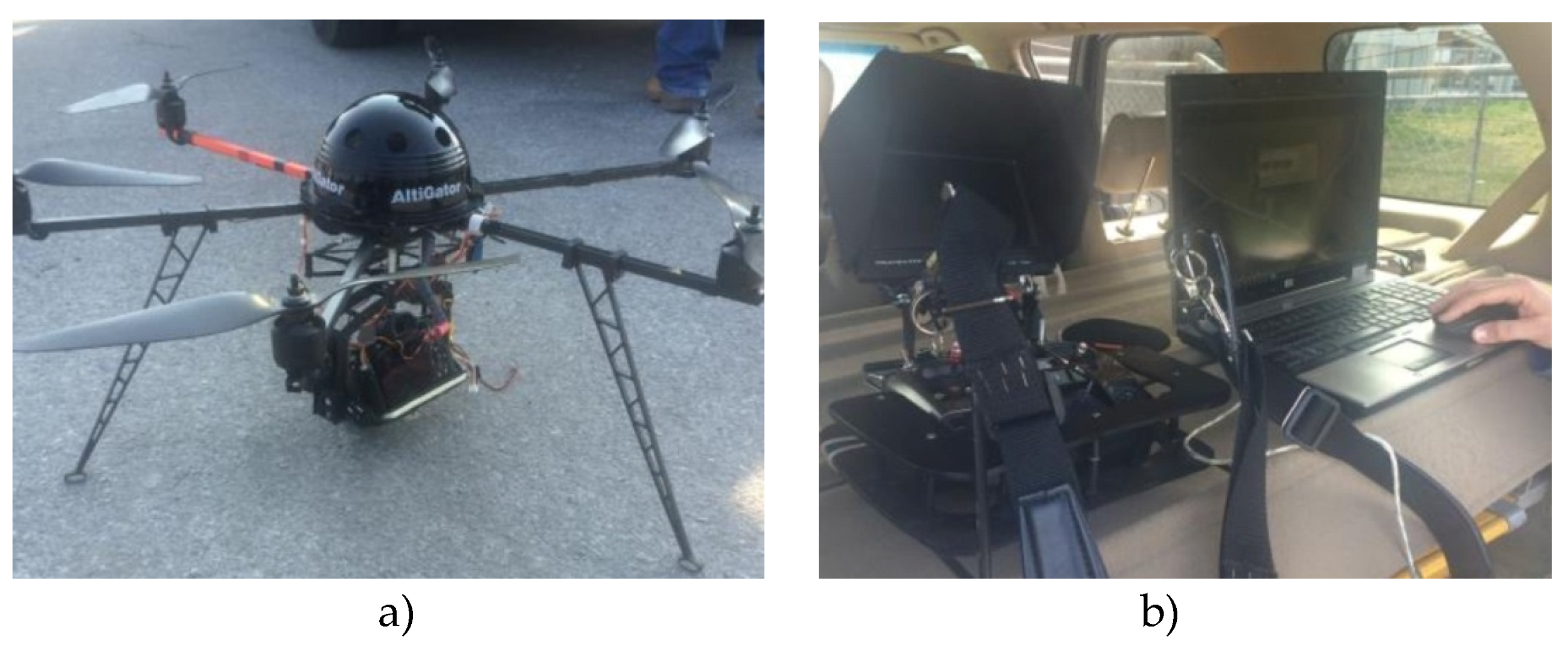
Photogrammetric recording of the real urban site II with small unmanned aerial vehicles (UAV) was performed for better presentation of the results using the GPR-TPS model of the certain UUI. In remote-sensing applications UAV are mostly used for photogrammetric purposes, the production of 3D-models of objects, digital surface models, digital terrain models (DTM) and orthophotos [39,40]. The Mikrokopter Hexa XL UAV system with six rotors, three of which rotate in a clockwise direction and three in a counterclockwise direction, was used. The UAV system is equipped with a SONY α7R digital camera system which is attached at the camera mount (see Figure 3). Basic geo-referencing of the captured photographs enables the built-in low-cost differential GNSS receiver, gyro sensor, barometric sensor, magnetic compass and flight control unit station which is used to control the UAV. MikroKopter MK tool software was used to programme the flights. The recording data were processed using the Imagine UAV programme module in the Erdas Imagine 2015 environment. A detailed description of the acquisition and processing is found in the Appendix.

3.1. Real Urban Site I

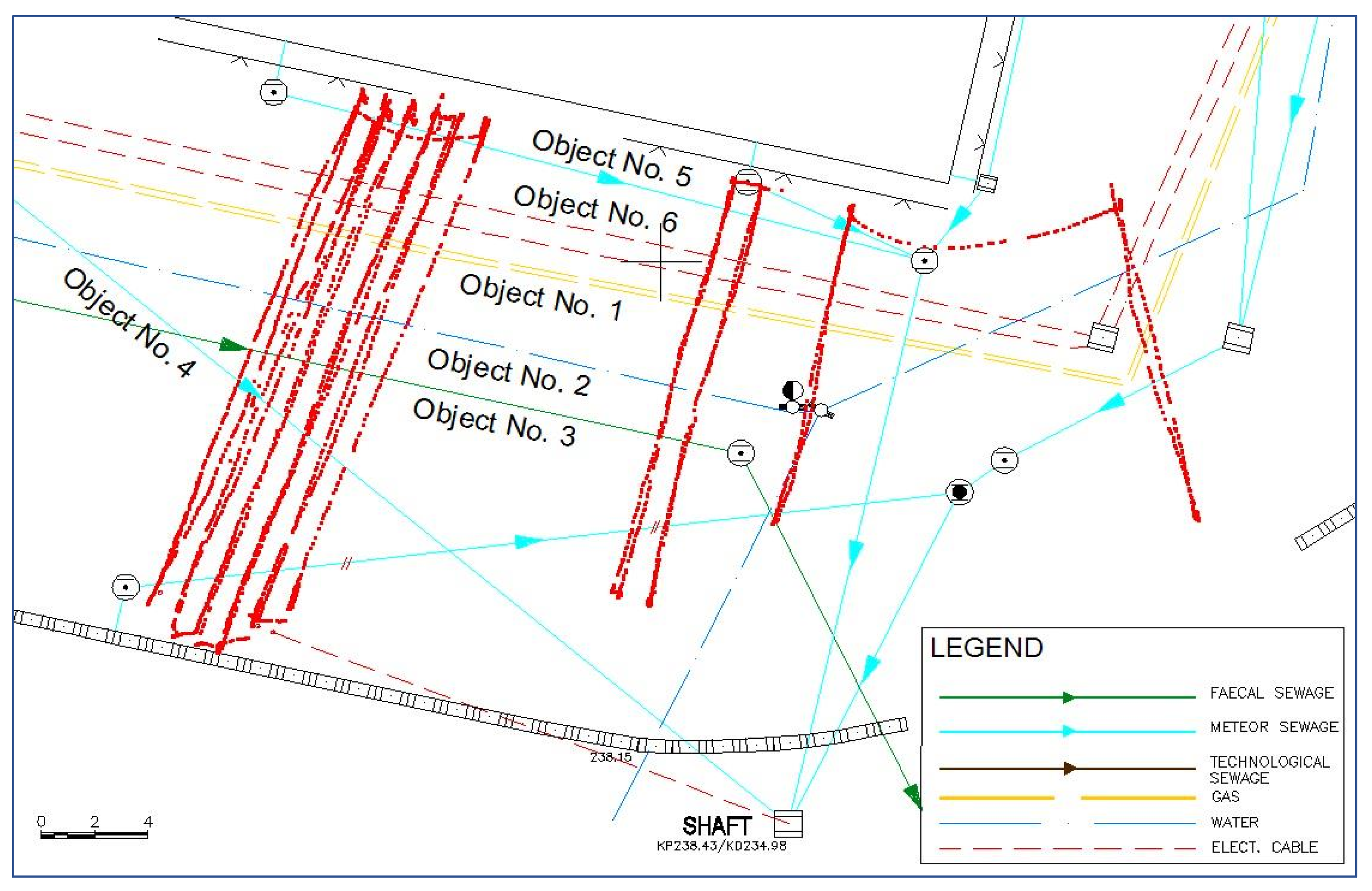
Measurements on nine random profiles in the S-N direction (red points) and 10 profiles in the N-S direction (grey points) were executed (see Figure 4). All profiles were recorded on a plane with an incline lower than 0.9%. The lengths of the profiles were from 11 to 22 m.
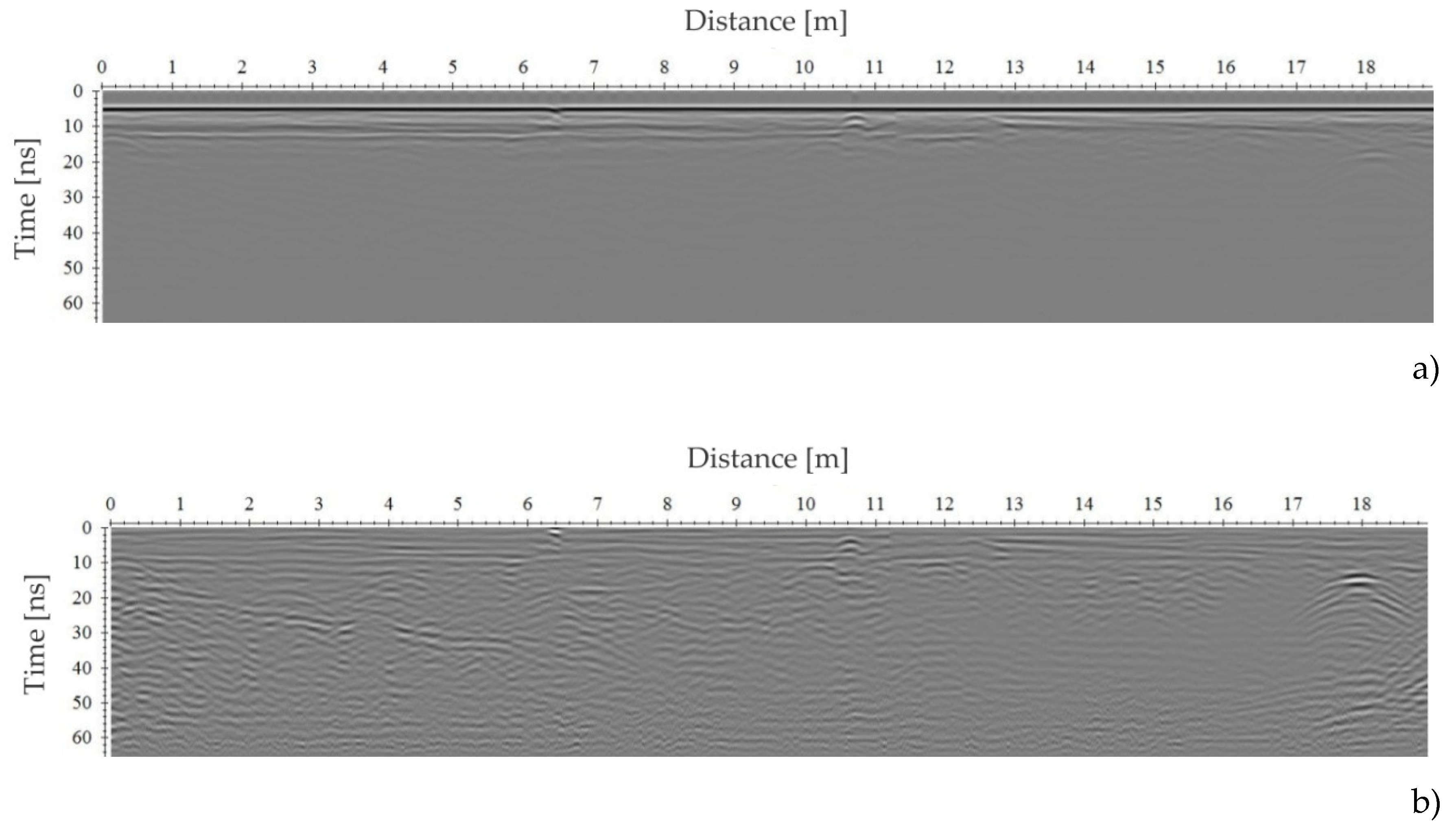
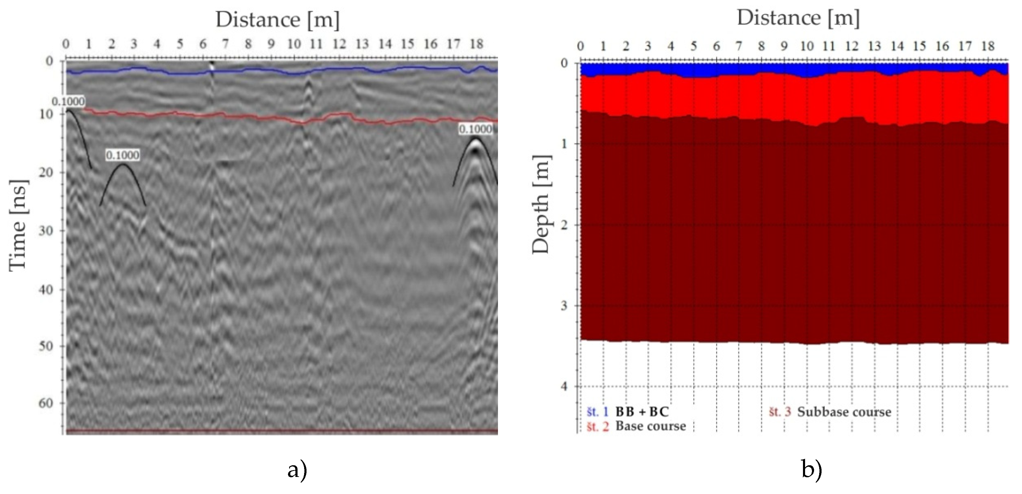
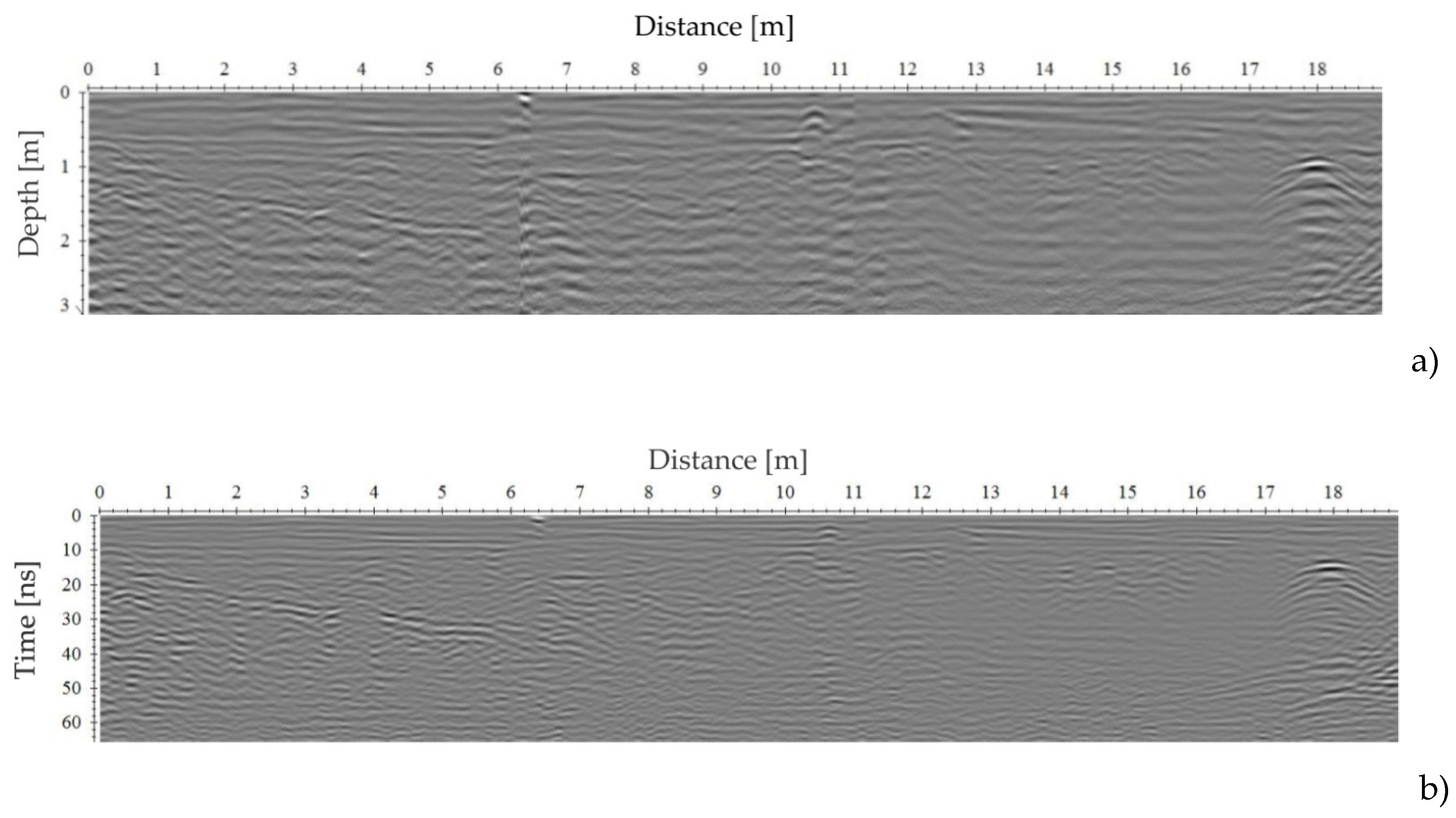
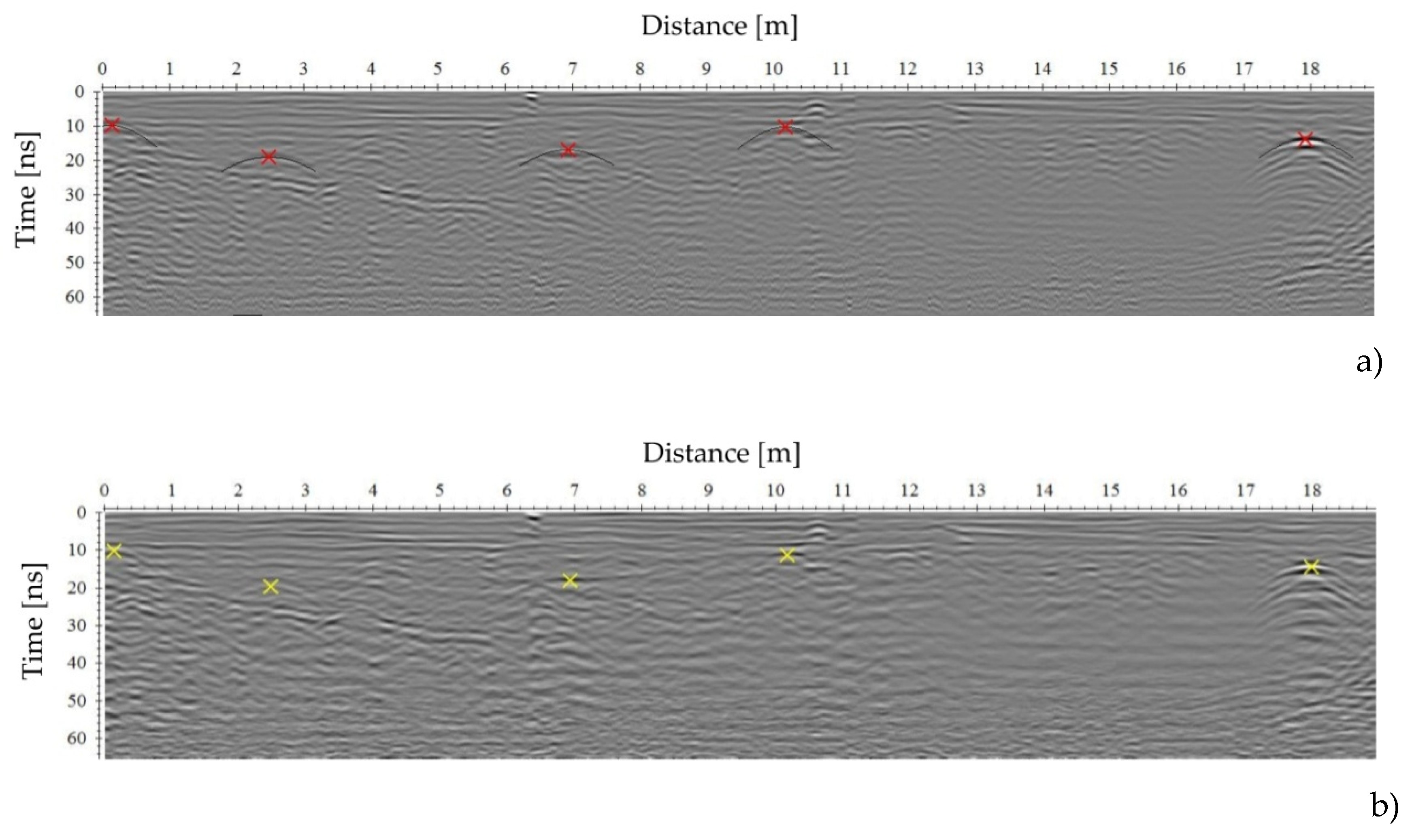
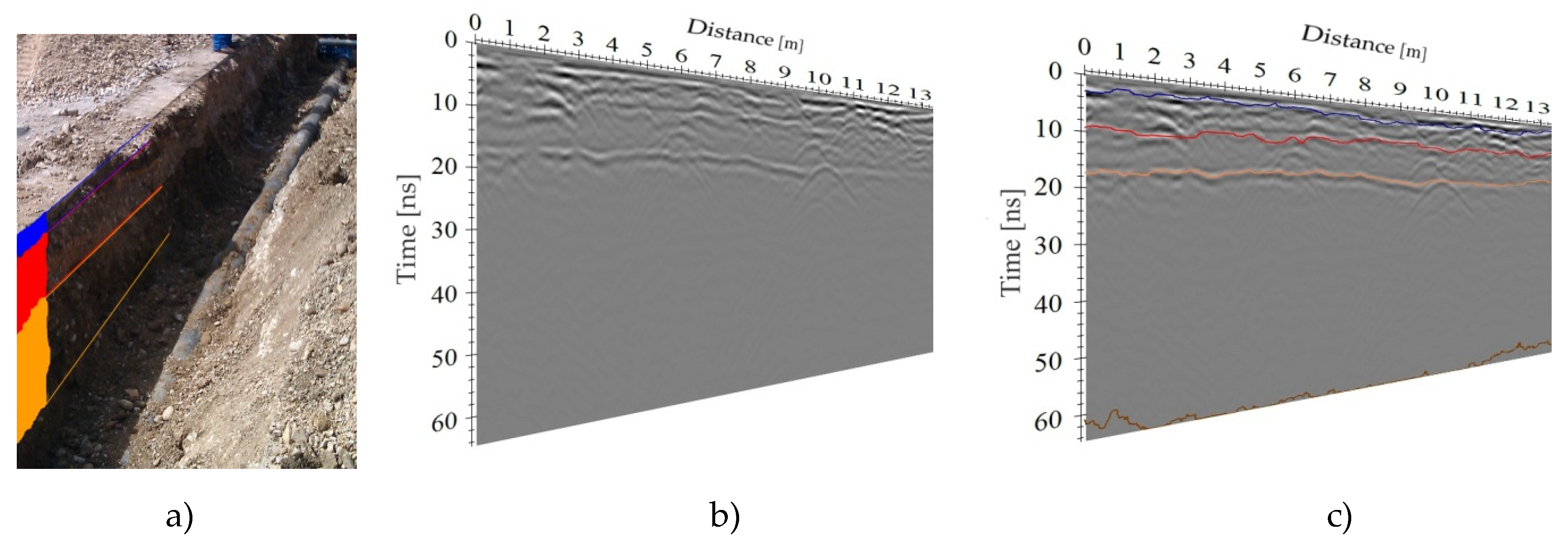
Figure 5, Figure 6, Figure 7 and Figure 8 and Table 5 show the data processing using the GPR-TPS model. According to the data processing model described in Šarlah et al. [5], the third phase of the processing was adapted to the demands of real test site I. The time cut function of the radargram was intentionally left out due to the explicit display of the depth range and the unrecognisability of target objects in the lower layers due to the presence of groundwater. The f-k filter was omitted from the model due to the non-disturbing easy air reflections of a nearby object. Process of the subtracting average of traces was used on 35 traces since it represents a great probability for elimination of the important horizontal reflections. The estimation of velocity of EMW propagation was executed without knowing the depths of target UUI in combination with the method of manual hyperbola fitting and the layer velocity method determined using individual layers of pavement structure (see Figure 6) [5]. Time to depth conversion was limited to a depth of 3.2 m. The topographic correction was preserved in the model despite an extremely small incline (see Figure 7). In relation to data processing, more details can be found in [5,41].

3.2. Real Urban Site II

The direction of GPR profiles was determined based on the technical documentation or the orientation of the majority of UUI. Twenty-eight parallel profiles in a S–N direction were measured. All profiles were recorded on a flat asphalt surface with a very small incline at a GPR speed of ≈0.5 m/s. The lengths of the profiles were 13.5–34.5 m.
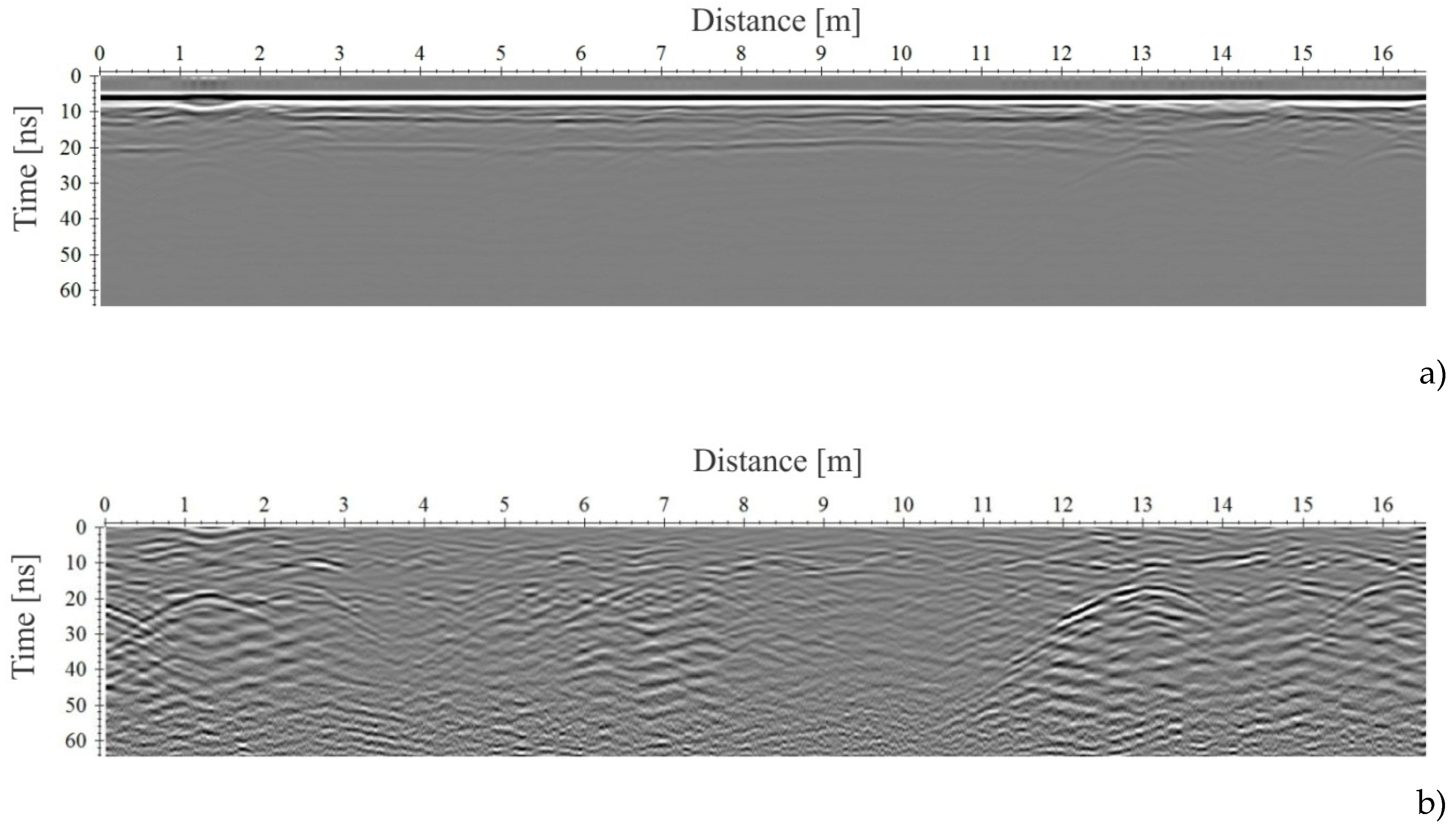
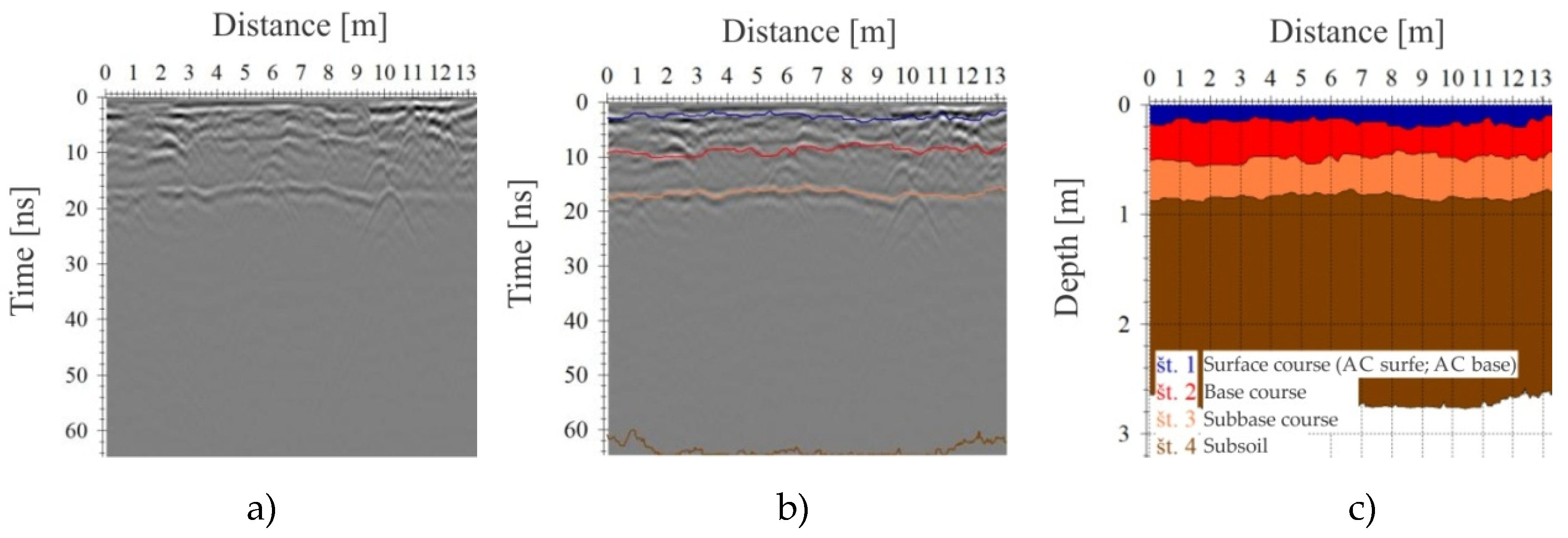
Figure 9, Figure 10, Figure 11 and Figure 12 and Table 6 show the capture and data processing when using the GPR-TPS model. According to the data processing model described in Šarlah et al. [5], the third phase of the processing was adapted to the demands of real test site II. The beginning of the first phase contained a calculation and corrigendum of zero time (5.20 ns), the signal delay elimination (50–64 ns) and a filter of background removal. The manual amplitude correction (0–32 dB) and the frequency band-pass filter of the tapered cosine window were used (230/320/580/750 MHz). The processing is the base for determining the lateral reflections of the pavement using the picking object method. The estimation of the EMW propagation velocity using the layer pick velocity method was the basis in the pavement structure (see Figure 10), while the method of hyperbola fitting was used in the subgrade soil. Time to depth conversion was limited to a depth of 3.1 m. The topographic correction was executed.
The procedure of signal elimination was executed prior to the manual selection of target objects in order to eliminate the horizontal reflections, e.g., layers of the pavement structure. The f-k filter was used in the model where for each individual profile, the parameter of the velocity range of a fan-shaped form, with which the set objective was reached, was defined, since the procedure was not satisfactory. A recognition analysis was done using a referential manual selection of the target objects (see Figure 12), which are later used on migrated radargrams. The deconvolution was additionally used on individual radargrams. It turned out to be useful in real urban site II in the area of iron heating pipes, which cause visibly multiplying reflections. Pavement structure layers estimations were made using a ‘semi-automatic’ phase follower picking method with a small tolerance.
Figure 13a shows UUI on the discussed real urban site II according to the data of CCUI. Figure 13b shows recorded UUI using the GPR-TPS. The cracks on the lined orthophoto recording, obtained using the UVA (see appendix) due to the mending of the asphalt mixture when renovating or reconstructing UUI (black lines along UUI), are very visible. The gas pipe (object No. 7) and the reconstructed water pipe (object No. 8), which were recorded in the open trenches using geodetic methods, are in compliance with the GPR-TPS model in terms of position and height. The rest of the UUI positionally stand out quite significantly or do not even exist in the official recordings, which is attributed to historical reasons, reconstructions and inconsistencies when recording. It can be seen that the UUI recorded using the GPS-TPS model is positionally quite in compliance with visible traits when renovating or reconstructing; it takes place through the middle of the excavation, which cannot be said for UUI according to the data from CCUI.

4. Results and Discussion

4.1. Real Urban Site I

The poor depth range, which is attributed to the characteristics of the subsurface and considerable moisture content and groundwater at depths of 1.2 to 1.5 m, was unified to all the processed GPR profiles of the real urban site I. Consequently, the target objects were not detected on the expected depths. Much better results were shown up to 1 m deep, where many well-expressed point reflections can be detected.
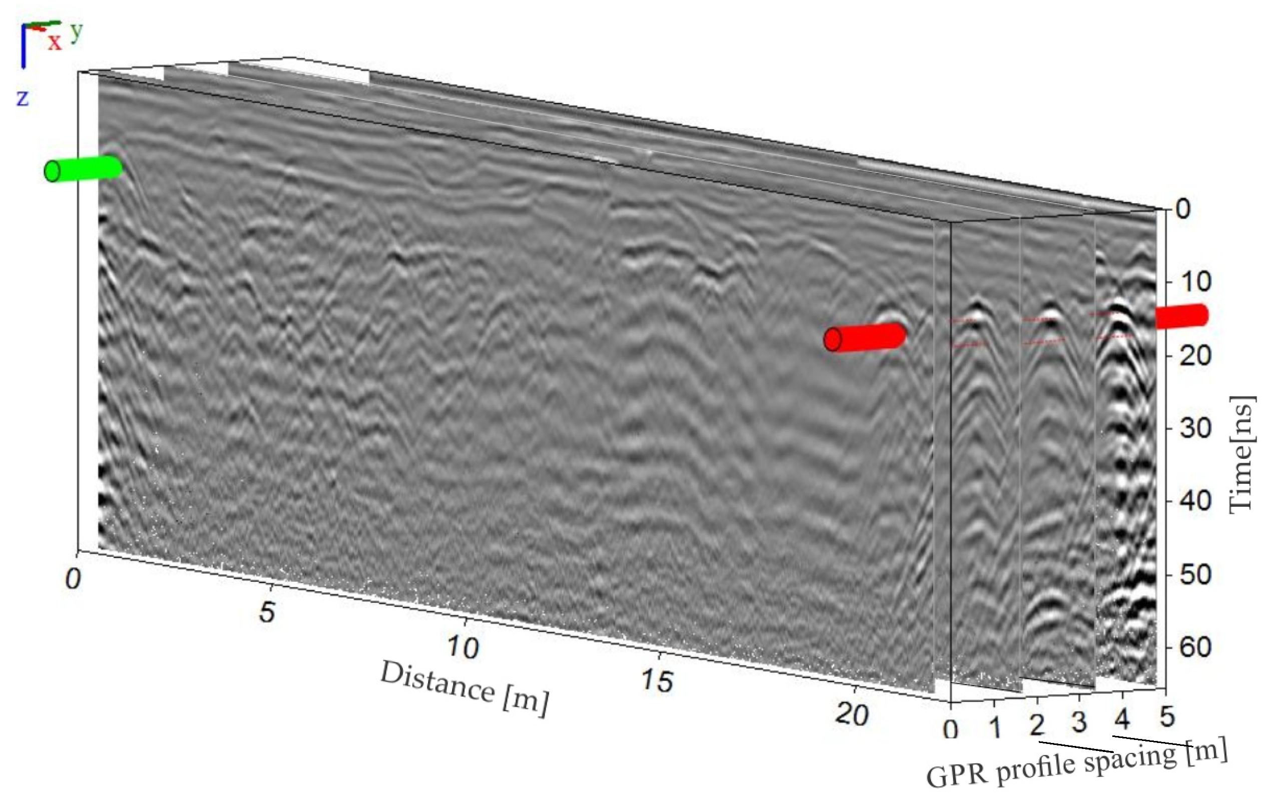
The point reflection of the PVC pipe for the technological sewage in the far north of real urban site I, together with the existing object, can be seen extremely well on all the profiles (see Figure 14; meteor sewage (object No. 5); red cylindrical object). Similar can be said for the meteor sewage in the southern part (see Figure 14 (green cylindrical object)). According to the references of the investors and building constructors, other reflections could be attributed to the abandoned UUI, in particular the real urban site I. During reconstruction of the area, the building constructor did not remove the abandoned objects and pipes, hence their correct position and depth are unknown.
The sections of the studied volume of the ground, which provide a detailed insight into the spatial relation of individual elements, are mostly used for the display of the results. This procedure is especially welcome for the interactive interpretation in a 3D environment.
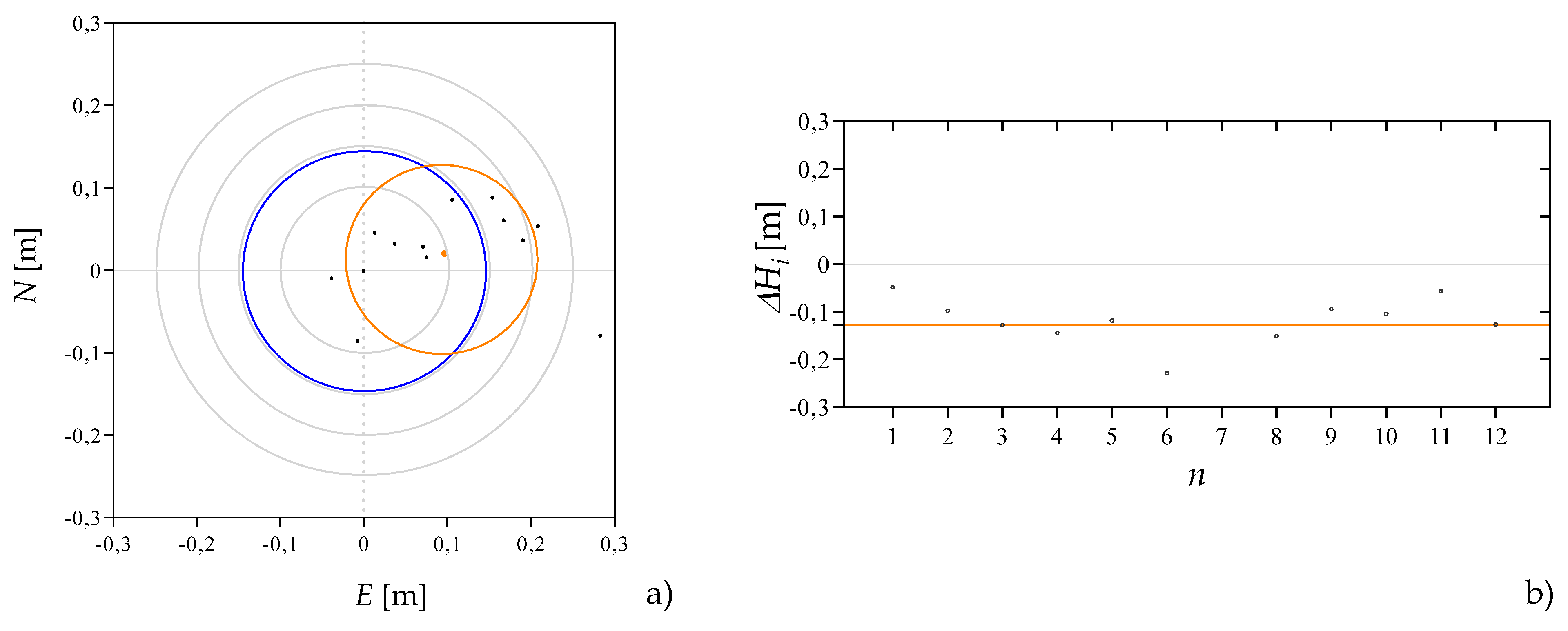
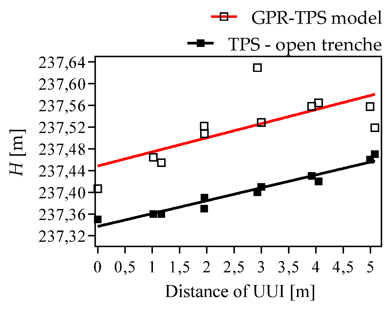
The assessment of the position accuracy and height described in Šarlah et al. [5] was executed by taking the comparison of 12 contributing reference points, as shown in Figure 15. The assessed positional accuracy of the GPR-TPS observations for the recorded UUI in the real urban site I is 0.146 m (positional (radial) RMSEpos). The positional (radial) standard deviation is σ p o s = 0.112 m, while the centre of gravity of the vectors lays 0.098 m from the starting point in an easterly direction. The assessed height accuracy is 0.134 m, while the σ Δ H is 0.093 m and the central tendency of the height devitations μ Δ H = −0.128 m. The 3xRMSE threshold, which provides an observation of gross errors—i.e., an error that was classified as an outlier - did not exceed any positional and height deviations. The difference between the true incline and that obtained [5] using the GPR-TPS model was 0° 30′ 08″ of the incline angle, as shown in Figure 16.

4.2. Real Urban Site II

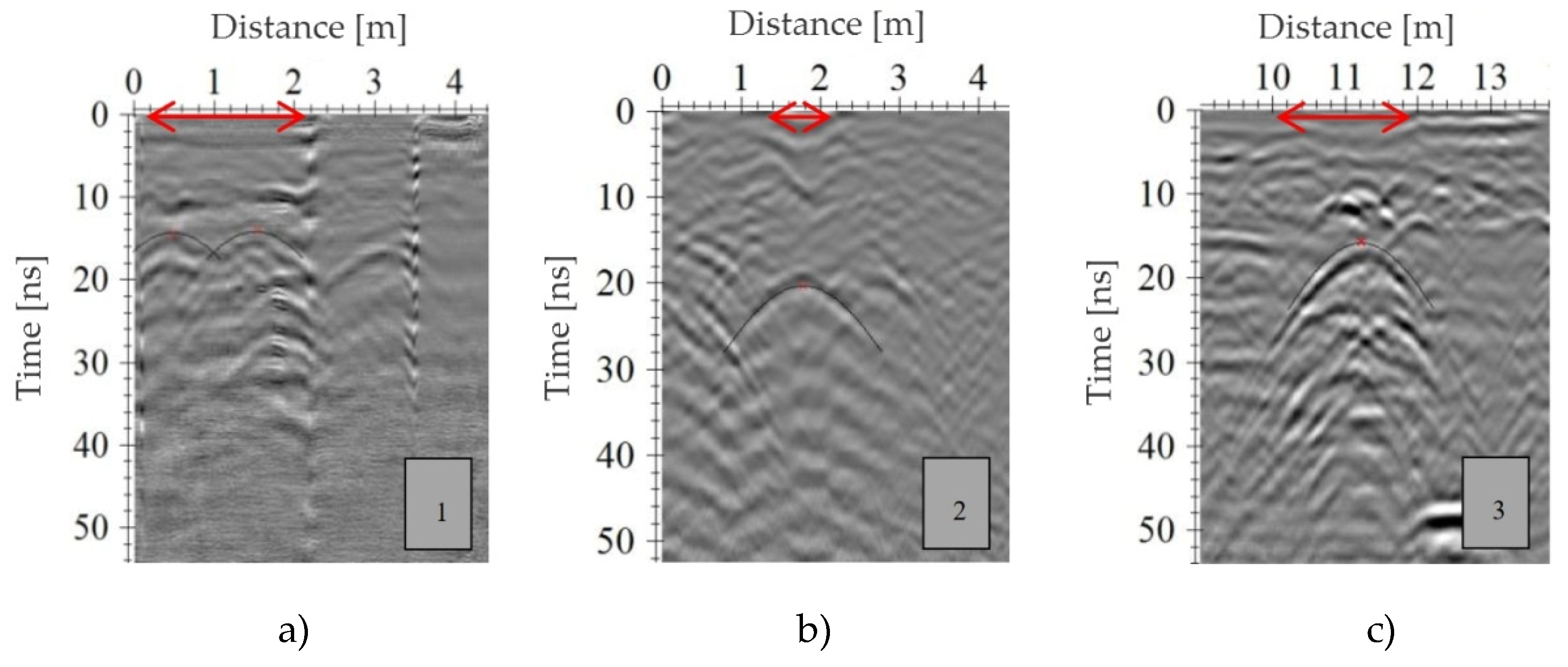
Bad resolution as a consequence of the damping and dispersion of the EMW in the medium is unified to some radargrams of the GPR profiles of the real urban site II. The cause is attributed to the leakage of the water through the cracks in the asphalt surface layer of the pavement structure. When laying, renovating and reconstructing UUI in the discussed area, the asphalt layers were cut. Narrow and wide cracks appear on the discussed area as can be seen in Figure 17. The insufficient execution and application of existing different asphalt mixtures probably affected the cracks along with the reconstruction, traffic and climate. Filling up the cracks in the sense of input of the appropriate bitumen mixture during maintenance was not executed. Therefore, water enters the pavement structure due to the porousness of the upper layers. GPR-TPS measurements were executed following two days of rain, which is seen on the damping of EMW and the quality and resolution of individual radargrams, where the water noticeably leaked through the cracks. Figure 18 shows the cracks in the covering layer and the effect of water leakage into the subbase and base course layers and subgrade soil on the radargram of the 25th profile of the 400 MHz antenna, where the damping of EMW is the most obvious.
Consequently, the fact of applicability of the GPR-TPS model when determining the position of faults and damages on UUI and detecting the losses on the water supply system can be concluded and confirmed. When discovering the losses, large relative water permittivity and changes of the physical characteristics of the subsurface, which has been stated by many authors [42,43,44,45], was exploited. On the less deteriorated part of the pavement structure, unburdened with daily traffic, which is presented by the emergency lane (western part of the intersection), water leakage in the pavement structure was not detected. Clearly visible reflections under the identical cracks due to the patching of the asphalt mixture for the needs of the UUI reconstruction are shown in Figure 19a–c. Anomalies of the asphalt surface layer of the pavement structure due to the reconstruction (1—heating system (objects No. 10, 11 and 12), 2—electronic cable duct (object No. 14) and 3—water supply system and gas line (objects No. 7 and 8) are visible. When processing radargrams, deconvolution on the area of the iron gas pipes was also used. The application of deconvolution on the radargram of the 19th profile of the 400 MHz antenna, on which there are iron gas pipes that cause visible multiplyaing reflections, is shown. The interval of starting and ending double time, which determines the autocorrelation, was limited from 5 to 11 ns, filtering traces on 10 ns, while the part of the elimination of the white noise was set at grade 50. Such a processed profile was strengthened using the function of manual signal gain for better visualisation. Following the deconvolution, the reflection of the intake and outtake of parallel heating pipes at an identical depth can be detected (see Figure 19).
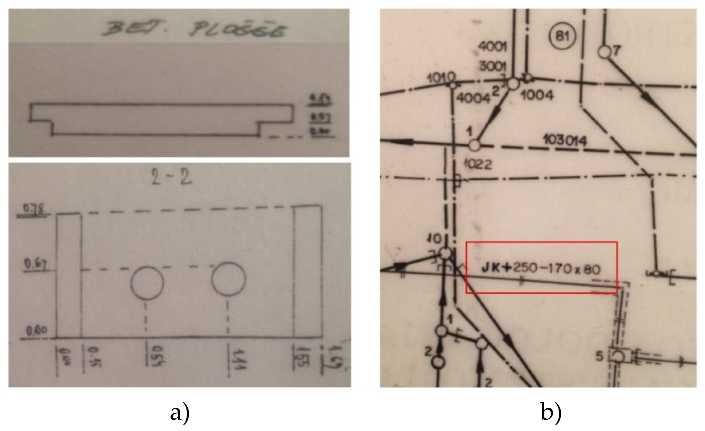
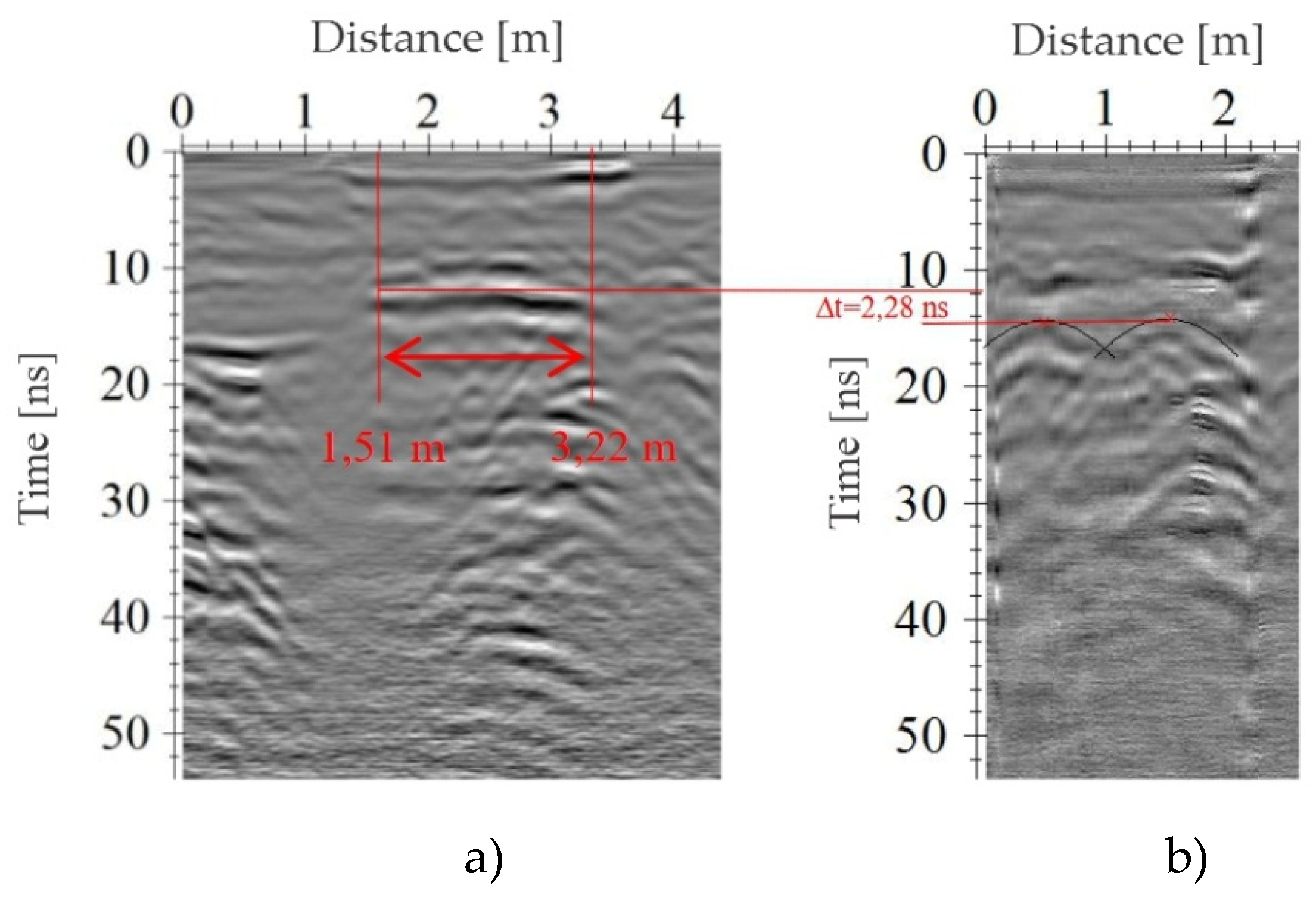
In CCUI, the steel pipes (objects No. 10 and 11) in the culvert (object No. 12) dimension 170 cm × 80 cm (see Table 4) were recorded at the real urban site II. The sketch and dimensions of the closest transverse profile (elaborate, no. 303/78-140 GZ) of the concrete plate and culvert with the built-in pipes, measured using geodetic methods and a radargram of the 20th GPR profile, are shown in Figure 20. From the sketch, the 14 cm thick concrete cover plate, under which there are just 4 cm on this part of the route from the bottom of the heating pipes, can be presupposed. While presupposing the relative permittivity of the concrete (4.5) and air (1) the referential double time from the top of the cover to the apex point of the isolated pipe would be 2.24 ns. From Figure 21, the culvert dimension (171 cm) and double time of the EMW propagation from the top of the cover of the culvert to the apex point of isolated heating pipes (2.28 ns), based on the suggested GPR-TPS model by which the compliance of the CCUI data and GPR-TPS observations can be confirmed. The radargram of the 20th profile was only partly processed (signal delay elimination, manual determination of zero-time, spatial filter of the background elimination, frequency band-pass filter, Kirchoff migration and repeated manual signal gain) due to the explicit display of the reflection of the concrete cover of the heating pipes.
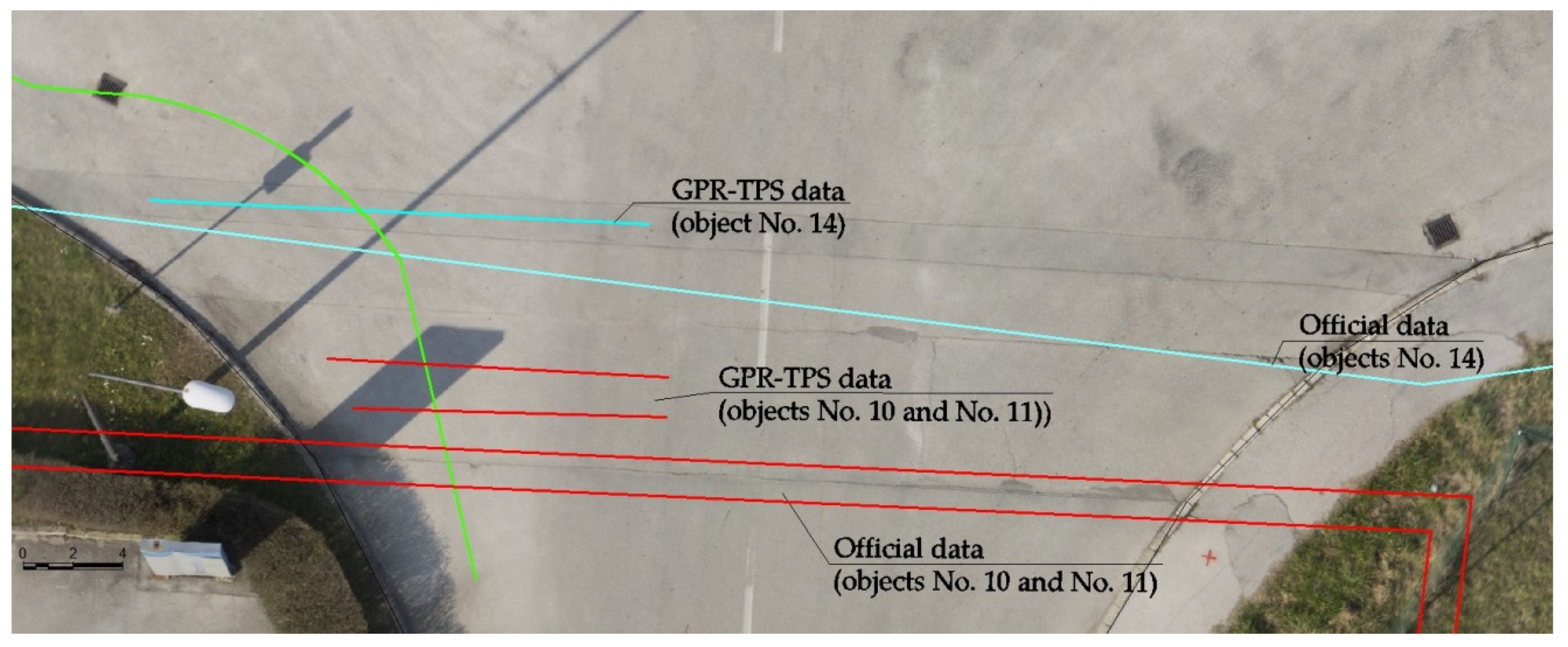
The degree of trust of the CCUI data in the heating system pipes (objects No. 10, 11 and 12) and the electronic communication duct (object No. 14) is low. It could be argued that the positions obtained according to the GPR-TPS model, are more correct. Patching of the asphalt mixture can be used as one of the criteria for validation of the results of the heating and electronic communication network position. The official position of the objective in CCUI does not match or positionally does not meet the position of the width of the patching of the asphalt surface during reconstruction. When displaying the position of officially valid CCUI data and that obtained using the GPR-TPS model, the positional correspondence of the patched asphalt mixture and the GPR-TPS data, as shown in Figure 22, is concluded.
The position accuracy and height assessment as described in Šarlah et al. [5] were executed by comparing 46 corresponding reference points of the drinking water supply pipe (object No. 7) and the gas pipe (object No. 8), as shown in Figure 23.
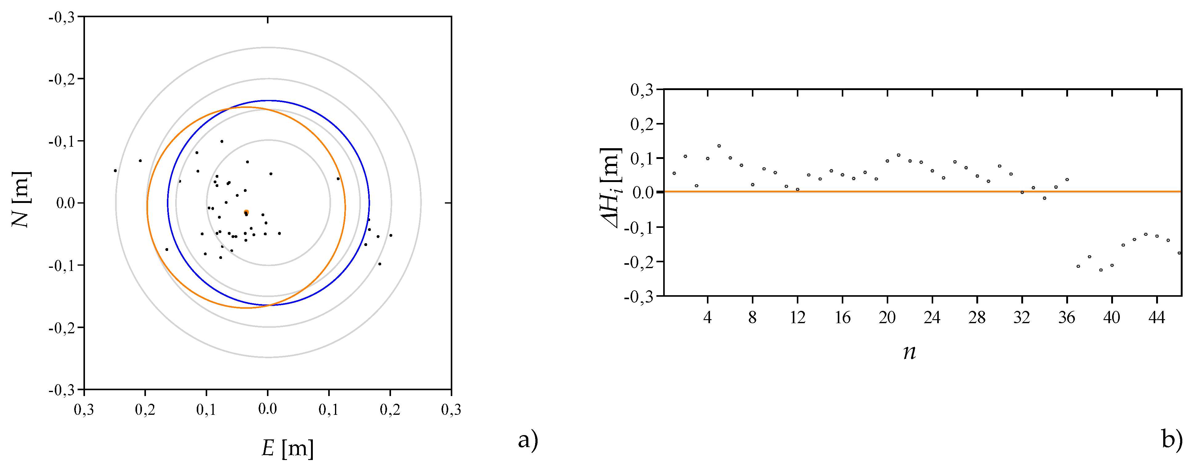
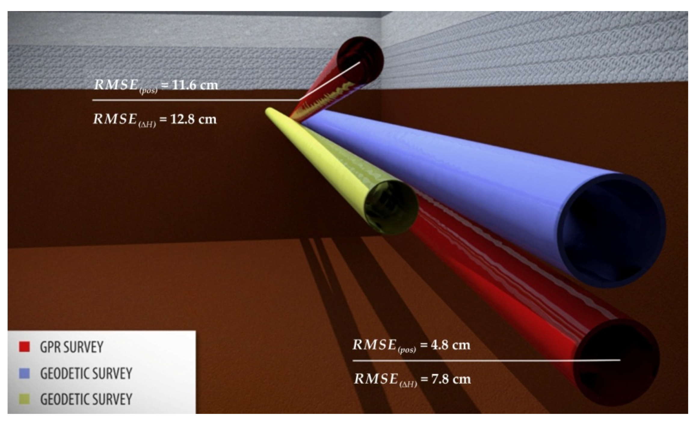
The assessed positional accuracy of the GPR-TPS observations when recording UUI at real urban site II is 0.114 m (positional (radial) RMSEpos). The positional (radial) standard deviation σpos = 0.111 m, the centre of gravity of the deviations´ vectors, lies 0.038 m from the starting point in a southeasterly direction. The assessed height accuracy is 0.100 m, while σH equals 0.103 m and the central tendency of the altitude deviations μH = 0.003 m (see Figure 24). The central tendency expresses the height movement of the target object according to the referential heights. A very good assessment of EMW propagation spreading velocity is shown in combination with the method of hyperbola fitting and the method of velocity determination based on individual layers of the pavement structure. None of the positional and height deviations surpassed the threshold of the 3 × RMSE.
Prior to the 3D-visualisation in three rectangular plains N, E and H for all the processed and migrated radargrams, the envelopes were calculated using the Hilbert transformation, in which the spatial relations between the chosen UUI can be seen more clearly.
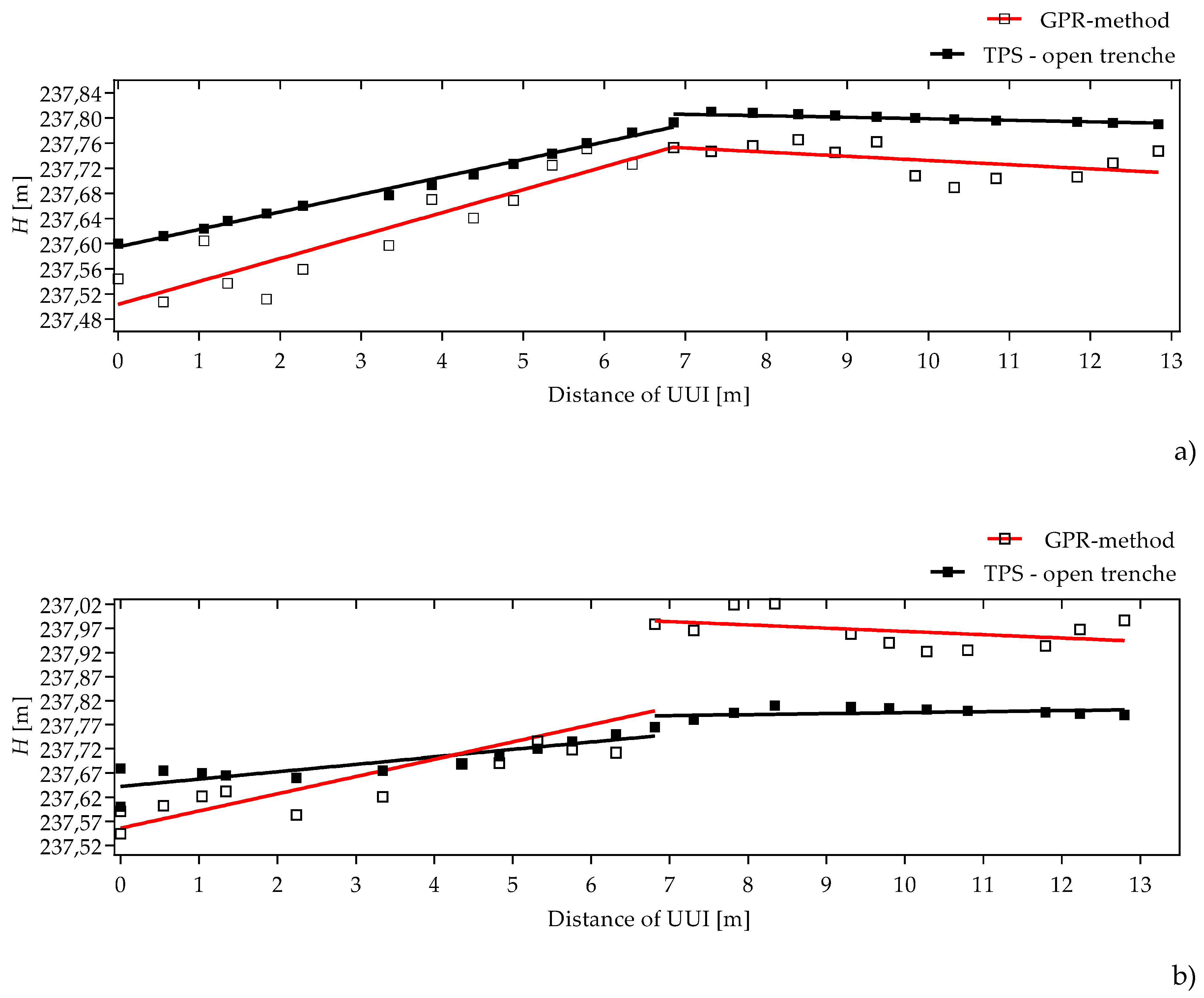
An assessment of the incline accuracy of the UUI was carried out by comparing the true incline and the incline obtained using the GPR-TPS model. By using linear regression, the best-fitting straight line was found [5]. Two best-fitting straight lines per pipe are proposed due to the inclination which varies as a result of joining of the two pipe sections. The difference between the true incline and that obtained using the GPR-TPS model was 1° 24′ 03″ of the incline angle, as shown in Figure 25.

5. Conclusions

Through this work, the authors have presented a suitable solution of the kinematic ground-penetrating radar (GPR) and self-tracking (robotic) terrestrial positioning system (GPR-TPS) model for the acquisition, processing and visualisation of underground utility infrastructure (UUI) with high 3D-georeferenced accuracy in a real urban environment. The kinematic GPR-TPS model used for this research was created for high-accuracy underground utilities’ 3D mapping in real urban field/testing pools [5]. Only minor adaptations were necessary for the transfer to fields of GPR investigation in real urban environments. The GPR-TPS model meets the recommended positional and height accuracy of second quality levels (QL-B) and gets close to first quality levels (QL-A) of the recognised UUI. By using the GPR-TTP model, the positional and height accuracy was less than 15 cm in the real urban sites I and II (RMSEpos = 14.6 cm; RMSEΔH = 13.4 cm and RMSEpos = 11.4 cm; RMSEΔH = 10.1 cm). The model proved to be a useful tool in determining the inclination of UUI, which is restricted by the height accuracy of the method (RMSEΔinc = 0.5° and RMSEΔinc = 1.5°). For better presentation of the results of UUI obtained using the GPR-TPS model, an additional recording using small UAV was executed. The UAV recording turned out to be extremely useful when confirming the actual position of the UUI, with the help of detected patches of the asphalt surfaces on the orthophoto. For this reason, the authors propose that the best way to map UUI is to cross both non-destructive techniques: the UAV photogrammetry to cover the surface-specific information, and the GPR-TPS model to cover subsurface information about UUI.
One of the obvious advantages of the kinematic GPR-TPS model for mapping the UUI is that it is not necessary to establish an orthogonal grid of the researched area, on which subsequently the lengths of the measured GPR profiles are usually linearised. The second obvious advantage of the suggested model is that, in compliance with the density of the contained positional and height points in real-time mode, the path of the movement of the GPR antenna presents a more credible position of the measured profile. The third advantage is in capturing accurate and continuous heights along the entire GPR trajectory which, with all the small changes in the shape of the surface, are key for the execution and research goals for exact topographic correction.
Of course, the GPR method has some limitations in recognitions and recordings of the UUI. Questions and gaps arising with the kinematic GPR-TPS model will have to be improved in terms of implementation of approaches to automatically identify and classify hyperbolic signatures. The success of the GPR-TPS model always depends on many aggravating circumstances, which appear in the real urban environment [1,2,3]. The example of the selected real urban site I, where the damping and dispersion of the EMW are caused due to the high moisture content or the large coarse ground tampon in the medium, proves that reflections—and with them the recognisability of the UUI—are fundamentally diminished. Similar conclusions also apply for the real urban site II, on which, due to the asphalt patches when reconstructing the UUI and consequently inappropriate maintenance, water has entered the road body. In this part, the extremely aggravating circumstances showed as a presence of moisture in the subsurface, and in some cases also to the extreme that the GPR method is unreliable or even completely useless.
It is presupposed that the results of the presented GPR-TPS model at the level of the development, as has been shown in recent years, have great potential in many areas. The social consequences of the suggested model are seen in the areas of spatial planning, obtaining building permission, protecting and insuring underground property, preventing damage, etc. Damage claims due to direct and indirect damage caused to UUI are also questionable. The first consequence, which can very quickly occur in the Republic of Slovenia, is that the investor or the stakeholder of the underground UUI in the phase of planning the intervention in the space or obtaining the adequate documentation (e.g., building permission), when there is insufficient knowledge or bad positional accuracy of the existing UUI in the area of the intervention, would have to record the sub-surface of the existing UUI, which would serve as a foundation for projections. This brings common conflicts, costs and material damage in spaces which occur due to not knowing the true position of the existing UUI. Nowadays, this is almost common practice in spatial areas or those of the legal regime of cultural heritage protection, where the GPR method is widely used in terms of previous archaeological studies of cultural heritage, which is ultimately cheaper than interventions in the spaces themselves. It is an encouraging fact that the GPR-TPS method is financially cheaper than digging interventions and repeating reconstructions of urban areas, especially when considering the fact that the position of the route of the UUI stands as an unknown when the intervention occurs.
Finally, through this work the authors have demonstrated that by using the suggested GPR-TPS model objectively it is possible to determine the quality (especially the parameter of accuracy) of the information obtained about the UUI in real urban area.

Supplementary Materials

The following are available online at https://www.mdpi.com/2072-4292/12/8/1228/s1, Video S1: Introduction video.

Author Contributions

N.Š., T.P. and B.M. conceived, designed and performed the research; N.Š. and B.M. analysed the data and discussed the results; T.A. contributed adjustment; N.Š. wrote the manuscript; T.P., T.A. and B.M. reviewed the manuscript and approved the final version. All authors have read and agreed to the published version of the manuscript.

Funding

This research received no external funding.

Acknowledgments

The authors would like to thank the anonymous reviewers for their valuable critiques and suggestions which improved the article.

Conflicts of Interest

The authors declare no conflict of interest.

Appendix A. Unmanned Aerial Vehicle Acquisition and Processing
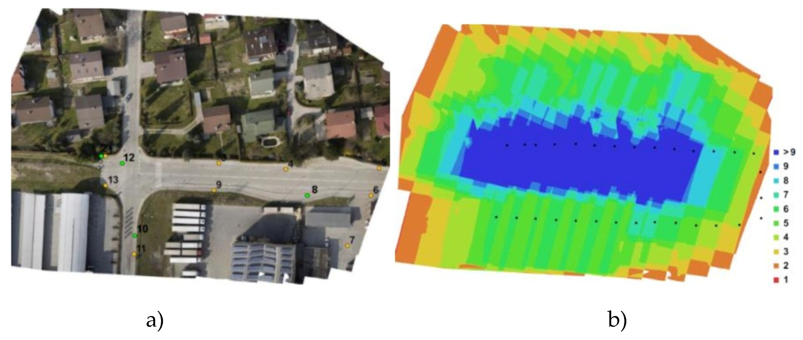
A complete photogrammetry workflow was used to generate an accurate orthomosaic with a spatial resolution of 1.17 cm on a surface of 2.56 ha with UAV. Indirect geo-referencing was applied using the measuring reference point that was deployed on the ground in the real urban site II before the flight. Nine ground control points, which were used for orientation of the recording and indirect geo-referencing of the photogrammetric block, were equally spread, stabilised and signalised across the area. Four points of the basic poligonometric net of the I. order, which are based on a rough positional and height assessment of the accuracy of the DTM, were used as the check points. Classic terrestrial measurement and the GNSS method were used when determining the horizontal position and the height of the ground control points and check points. The recording using UAV was executed following the execution of the geodetic measurements and determination of the area of the flight. The UAV recording was taken with an 80% longitudinal overlap, a 40% lateral overlap, a flying altitude of 90 m, a 36-megapixel resolution (7340 × 4912), a 35 mm fixed focal length, and an average pixel (4.88 μm × 4.88 μm).
Joining the images into a photogrammetric block takes place through the tie points, which are automatically determined using dense image matching. In this phase of the processing, where the data only connect relatively with each other, the elements of the interior orientation of the camera (coordinates of the main point of the recording, the focal length, the size of the pixel and the parameters of radial and/or tangential optical distortion) are also calculated. The parameters of interior orientation for the cameras were determined using laboratory calibration [46]. The relatively oriented block of recording which is based on the coordinates of ground control points (see Figure A1), was transformed into the referential coordinate system. Meanwhile, the parameters of the exterior orientation of each recording in the block was also calculated. The photogrammetric point cloud was calculated in the adjustment using oriented recordings and automatically measured image coordinates of the tie points [47]. The cloud of points is later classified on the ground and non-ground points. From the ground points, the DTM which serves to orthorectify the recordings is calculated using interpolation. The final orthophoto of the real urban site II was taken using a mosaicking of the orthophotos, which were taken from the singular recordings.
Figure A1. (a) Position of the ground control (yellow) and check points (green) of the recording area; (b) overlapping 30 images’ frequency and camera position.
Remotesensing 12 01228 g0a1
Checking the accuracy of DTM data in 3D space is carried out by comparing the DTM data with reference values on checkpoints. The reference values of the checkpoints were determined in the field using geodetic methods (GNSS) with very high accuracy. The accuracy of DTM is expressed using vertical accuracy measures and horizontal (planimetric) accuracy measures [48,49]. The distribution and number of checkpoints, in this case, was not satisfactory for an actual quality assessment, however, the accuracy of the orthophoto was at least approximately defined. Since the normal distribution of errors was not proved, robust accuracy measures were used, namely: 50% quantile Q|∆i|(0.50) and 95% quantile Q|∆i|(0.95) of the absolute values of the errors and normalised median absolute deviation (NMAD). Based on the robust accuracy measures Q|∆H|(0.95) = 5.0 cm it was assessed that the height accuracy of DTM is: NMAD = 2.2 cm, Q|∆i|(0.50) = −1.4 cm; the positional accuracy of the orthophoto on the coordinate axis y Q|y|(0.95) = 1.7 cm (NMAD = 1.2 cm, Q|∆i|(0.50) = 0.003 cm) and coordinate axis x Q|x|(0.95) = 4.7 cm (NMAD = 2.7 cm, Q|∆i|(0.50) = −0.007 cm). The great difference between the coordinate axes is attributed to the extremely low number of control points. The robust accuracy measure of the orthophoto according to the horizontal position of Q|xy|(0.95) was 4.9 cm.

References

  1. Annan, A.P. Ground Penetrating Radar: Principles, Procedures & Applications; Sensors & Software Inc.: Mississauga, ON, Canada, 2003. [Google Scholar]
  2. Jol, H.M. Ground Penetrating Radar: Theory and Applications; Elsevier Science: Amsterdam, The Netherlands; Oxford, UK, 2009. [Google Scholar]
  3. Persico, R. Introduction to Ground Penetrating Radar: Inverse Scattering and Data Processing; Wiley-IEEE Press: Hoboken, NJ, USA, 2014. [Google Scholar]
  4. Wai-Lok Lai, W.; Dérobert, X.; Annan, P. A review of Ground Penetrating Radar application in civil engineering: A 30-year journey from Locating and Testing to Imaging and Diagnosis. NDT E Int. 2018, 96, 58–78. [Google Scholar] [CrossRef]
  5. Šarlah, N.; Podobnikar, T.; Mongus, D.; Ambrožič, T.; Mušič, B. Kinematic GPR-TPS Model for Infrastructure Asset Identification with High 3D Georeference Accuracy Developed in a Real Urban Test Field. Remote Sens. 2019, 11, 1457. [Google Scholar] [CrossRef] [Green Version]
  6. Ayala-Cabrera, D.; Herrera, M.; Izquierdo, J.; Ocaña-Levario, S.J.; Pérez-García, R. GPR-Based Water Leak Models in Water Distribution Systems. Sensors 2013, 13, 15912–15936. [Google Scholar] [CrossRef]
  7. Metje, N.; Atkins, P.R.; Brennan, M.J.; Chapman, D.N.; Lim, H.M.; Machell, J.; Muggleton, J.M.; Pennock, S.; Ratcliffe, J.; Redfern, M.; et al. Mapping the underworld—State-of-the-art review. Tunn. Undergr. Sp. Tech. 2007, 5–6, 568–586. [Google Scholar] [CrossRef]
  8. Mohar Bastar, K.; Šarlah, N. The influence of the cost reduction directive on the broadband roll. Teh. Vjesn. 2019, 96, 58–78. [Google Scholar]
  9. Šarlah, N. Exchange Formats for Interoperability Support of the Consolidated Cadastre of Public Infrastructure Information System. Master’s Thesis, University of Ljubljana, Faculty of Civil and Geodetic Engineering, Ljubljana, Slovenia, 2008. Available online: https://repozitorij.uni-lj.si/Dokument.php?id=84240&lang=slv (accessed on 27 July 2019).
  10. ASCE CI/ASCE38-02 American Society of Civil Engineers; Standard Guidelines for the Collection and Depiction of Existing Subsurface Utility Data. ASCE 2002, 38, 1–20.
  11. AS 5488—2013. Australian Standard: Classification of Subsurface Utility Information. 2013. Available online: https://nulca.com.au/db_uploads/5488-2013_V2.pdf (accessed on 21 April 2018).
  12. British Standars Institutions. British Standard: Specification for Underground Utility Detection, Verification and Location Institute of Civil Engineering; ICE PAS 128: 2014; BSI: London, UK, 2014; Available online: https://shop.bsigroup.com/ProductDetail/?pid=000000000030267400 (accessed on 1 April 2020).
  13. Surveying and Mapping Authority of the Republic of Slovenia. Exchange Format and the Code Lists of the Consolidated Cadastre of Utility Infrastructure. 2018. Available online: http://www.e-prostor.gov.si/fileadmin/GJI/elaborati/Format_sifrant_6.02.pdf (accessed on 19 May 2019).
  14. Šarlah, N.; Kumer, J.; Kuzmič, M.; Jud, S.; Mesner, A.; Mlinar, J.; Klemenčič, G.; Šelek, L. Guideline for Underground Utility Mapping in Slovenia 2010. Available online: https://www.researchgate.net/publication/263949930_GUIDELINE_FOR_UNDERGROUND_UTILITY_MAPPING_IN_SLOVENIA (accessed on 19 May 2019).
  15. Grandjean, G.; Gourry, J.C.; Bitri, A. Evaluation of GPR techniques for civil-engineering applications: A study on a test site. J. Appl. Geophys. 2000, 45, 141–156. [Google Scholar] [CrossRef]
  16. Mušič, B.; Podobnikar, T.; Šarlah, N. Recording of Buried Utility Pipes with a Non-Invasive Ground-Penetrating Method. Geographic Information System in Slovenia 2011–2012. 2012. Available online: https://www.academia.edu/2519279/RECORDING_OF_BURIED_UTILITY_PIPES_WITH_NONINVASIVE_GROUND_PENETRATING_METHOD (accessed on 30 May 2019).
  17. Aaltonen, J.; Nissen, J. Geological mapping using GPR and differential GPS positioning: A case. In Proceedings of the Ninth International Conference on Ground Penetrating Radar, Santa Barbara, CA, USA, 29 April–2 May 2002. [Google Scholar]
  18. Jaw, S.W.; Hashim, M. Locational accuracy of underground utility mapping using ground-penetrating radar. Tunn. Undergr. Space Technol. 2013, 35, 20–29. [Google Scholar] [CrossRef]
  19. Li, S.; Cai, H.; Kamat, V.R. Uncertainty-aware geospatial system for mapping and visualising underground utilities. Autom. Constr. 2015, 53, 105–119. [Google Scholar] [CrossRef]
  20. Boniger, U.; Tronicke, J. On the Potential of Kinematic GPR Surveying Using a Self-Tracking Total Station: Evaluating System Crosstalk and Latency. IEEE Trans. Geosci. Remote Sens. 2010, 48, 3792–3798. [Google Scholar] [CrossRef]
  21. Böniger, U.; Tronicke, J. Improving the interpretability of 3D GPR data using target-specific attributes: Application to tomb detection. J. Archaeol. Sci. 2010, 37, 672–679. [Google Scholar] [CrossRef]
  22. Allroggen, N.; Tronicke, J.; Delock, M.; Böniger, U. Topographic migration of 2D and 3D ground-penetrating radar data considering variable velocities. Near Surf. Geophys. 2014, 13, 253–259. [Google Scholar] [CrossRef]
  23. Bilal, M.; Khan, W.; Muggleton, J.; Rustighi, E.; Jenks, H.; Pennock, S.R.; Atkins, P.R.; Cohn, A. Inferring the most probable maps of underground utilities using Bayesian mapping model. J. Appl. Geophys. 2018, 150, 52–66. [Google Scholar] [CrossRef]
  24. Dou, Q.; Wei, L.; Magee, D.R.; Atkins, P.R.; Chapman, D.N.; Curioni, G.; Goddard, K.F.; Hayati, F.; Jenks, H.; Metje, N.; et al. 3D Buried Utility Location Using A Marching-Cross-Section Algorithm for Multi-Sensor Data Fusion. Sensors 2016, 16, 1827. [Google Scholar] [CrossRef] [PubMed] [Green Version]
  25. Chen, H.; Cohn, A.G. Buried utility pipeline mapping based on multiple spatial data sources: A Bayesian data fusion approach. In Proceedings of the Twenty-Second International Joint Conference on Artificia Intelligence, Barcelona, Spain, 16–22 July 2011; Available online: https://www.researchgate.net/publication/220815962_Buried_Utility_Pipeline_Mapping_Based_on_Multiple_Spatial_Data_Sources_A_Bayesian_Data_Fusion_Approach (accessed on 20 March 2020).
  26. Cheng, N.-F.; Tang, H.-W.; Chan, C.-T. Identification and positioning of underground utilities using ground-penetrating radar (GPR). Sustain. Environ. Res. 2013, 23, 141–152. [Google Scholar]
  27. Gabryś, M.; Kryszyn, K.; Ortyl, Ł. GPR surveying method as a tool for geodetic verification of GESUT database of utilities in light of BSI PAS128. Rep. Geod. Geoinf. 2019, 107, 49–59. [Google Scholar] [CrossRef] [Green Version]
  28. Ghozzi, R.; Lahouar, S.; Besbes, K.; Souani, C. Mapping of Sewer Lines Using GPR: A Case Study in Tunisia. Data 2018, 3, 40. [Google Scholar] [CrossRef] [Green Version]
  29. Ismail, N.A.; Saad, R.; Muztaza, N.M.; Ali, N. Predictive mapping of underground utilities using ground-penetrating radar. Casp. J. Appl. Sci. Res. 2013, 2, 104–108. [Google Scholar]
  30. Jeng, Y.; Chen, C.-S. Subsurface GPR imaging of a potential collapse area in urban environments. Eng. Geol. 2012, 147-148, 57–67. [Google Scholar] [CrossRef]
  31. Metwaly, M. Application of GPR technique for subsurface utility mapping: A case study from an urban area of Holy Mecca, Saudi Arabia. Measurement 2015, 60, 139–145. [Google Scholar] [CrossRef]
  32. Porsani, J.L.; Ruy, Y.B.; Ramos, F.P.; Yamanouth, G.R.B. GPR applied to mapping utilities along the route of Line 4 (yellow) subway tunnel construction in São Paulo City, Brazil. J. Appl. Geophys. 2012, 80, 25–31. [Google Scholar] [CrossRef]
  33. Sagnard, F.; Norgeot, C.; Derobert, X.; Baltazart, V.; Merliot, E.; Derkx, F.; Lebental, B. Utility detection and positioning on the urban site Sense-City using Ground-Penetrating Radar systems. Measurement 2016, 88, 318–330. [Google Scholar] [CrossRef] [Green Version]
  34. Van der Kruk, J. Three-Dimensional Imaging of Multi-Component GPR Data. Ph.D. Thesis, Delft University of Technology, Delft, The Netherlands, 2001. Available online: http://e-collection.library.ethz.ch/eserv/eth:24077/eth-24077-01.pdf (accessed on 13 March 2019).
  35. Leckebusch, J. Ground Penetrating Radar: A Modern Three-dimensional Prospection Method. Archaeol. Prospect. 2003, 10, 213–240. [Google Scholar] [CrossRef]
  36. Luo, T.X.; Lai, W.W.; Chang, R.K.; Goodman, D. GPR imaging criteria. J. Appl. Geophys. 2019, 165, 37–48. [Google Scholar] [CrossRef]
  37. Kirschner, H.; Stempfhuber, W. The Kinematic Potential of Modern Tracking Total Stations—A State of the Art Report on the Leica TPS1200+. In Proceedings of the 1st International Conference on Machine Control & Guidance, Kinematic Measurement and Sensor Technology I (Local Systems), Zurich, Switzerland, 24–26 June 2008; pp. 51–60. [Google Scholar]
  38. Leica TPS1200+. User Manual; Leica Geosystems: Heerbrugg, Switzerland, 2008; pp. 1–209. Available online: http://webarchiv.ethz.ch/geometh-data/student/anleitungen/leicaman/tps1200/TPS1200_User_en.pdf (accessed on 14 April 2018).
  39. Siebert, S.; Teizer, J. Mobile 3D mapping for surveying earthwork projects using an Unmanned Aerial Vehicle (UAV) system. Automat. Constr. 2014, 41, 1–14. [Google Scholar] [CrossRef]
  40. Fraga-Lamas, P.; Ramos, L.; Mondéjar-Guerra, V.; Fernández-Caramés, T.M. A Review on IoT Deep Learning UAV Systems for Autonomous Obstacle Detection and Collision Avoidance. Remote Sens. 2019, 11, 2144. [Google Scholar] [CrossRef] [Green Version]
  41. Bianchini Ciampoli, L.; Tosti, F.; Economou, N.; Benedetto, F. Signal Processing of GPR Data for Road Surveys. Geosciences 2019, 9, 96. [Google Scholar] [CrossRef] [Green Version]
  42. Hyun, S.-Y.; Jo, Y.-S.; Oh, H.-C.; Kim, S.-Y.; Kim, Y.-S. A laboratory scaled-down model of ground-penetrating radar for leak detection of water pipes. Meas. Sci. Technol. 2007, 18, 2791–2799. [Google Scholar] [CrossRef]
  43. Huisman, J.A.; Hubbard, S.S.; Redman, J.D.; Annan, A.P. Measuring Soil Water Content with Ground Penetrating Radar: A Review. Vadose Zone J. 2003, 2, 476–491. [Google Scholar] [CrossRef]
  44. Liu, G.; Jia, Y.; Liu, H.; Qiu, H.; Qiu, D.; Shan, H. A Case Study to Detect the Leakage of Underground Pressureless Cement Sewage Water Pipe Using GPR, Electrical, and Chemical Data. Environ. Sci. Technol. 2002, 36, 1077–1085. [Google Scholar] [CrossRef]
  45. Stampolidis, A.; Soupios, P.; Vallianatos, F.; Tsokas, G.N. Detection of leaks in buried plastic water distribution pipes in urban places—A case study. In Proceedings of the 2nd International Workshop on Advanced Ground Penetrating Radar, Delft, The Netherlands, 14–16 May 2003; pp. 120–124. [Google Scholar]
  46. Kraus, K. Photogrammetrie, Band 1, Geometrischs Informationen aus Photographien und Laserscanneraufnahmen; Walter de Gruyter: Berlin, Germany, 2009. [Google Scholar]
  47. Rosnell, T.; Honkavaara, E. Point Cloud Generation from Aerial Image Data Acquired by a Quadrocopter Type Micro Unmanned Aerial Vehicle and a Digital Still Camera. Sensors 2012, 12, 453–480. [Google Scholar] [CrossRef] [PubMed] [Green Version]
  48. Höhle, J.; Potuckova, M. EuroSDR No. 60: Assessment of the Quality of Digital Terrain Models. Off. Publ. Eur. Spat. Data Res. 2009, 60, 1–85. [Google Scholar]
  49. Höhle, J.; Höhle, M. Accuracy assessment of digital elevation models by means of robust statistical methods. ISPRS J. Photogramm. 2009, 64, 398–406. [Google Scholar] [CrossRef] [Green Version]
Figure 1. (a) On the map the position of real urban sites I and II are marked; (b) Presentation of a total of 16,878 points determined using the ground-penetrating radar with a terrestrial positioning system (GPR-TPS) model (red points show 28 profiles in the S–N direction) i.e., real urban site II; (c) Presentation of a total of 15,423 points determined using the GPR-TPS model (red points show 19 profiles in the S–N direction) i.e., real urban site I.
Remotesensing 12 01228 g001
Figure 2. (a) Leica TCRP 1201+ electronic tracking total station with automatic recognition of the reflector located in testing field I; (b) SIR-3000 GPR system, 400 MHz mono-static antenna: (1) tow bar, (2) measuring wheel, (3) Leica GRZ4 reflector and (4) adapter made for reflector; (c) control unit and Bluetooth RS 232 adapter (BT-232B-E): (1) external dipole antenna.
Remotesensing 12 01228 g002
Figure 3. (a) Unmanned aerial vehicle—hexacopter; (b) ground control station.
Remotesensing 12 01228 g003
Figure 4. Presentation of a total of 15,423 points, determined by the GPR-TPS model (red points) on the geodetic plan showing UUI (see Table 4).
Remotesensing 12 01228 g004
Figure 5. Processing of profile 8 using the GPR-TPS model: (a) rough GPR observations; (b) subtracting a constant shift on the radargram with a time interval of the calculation of an average of 50–70 ns; manual determination of zero time at the first positive apex point of signal using a manual setting of zero (4.41 ns), spatial filter of background removal, frequency band-pass filter of tapered cosine window (250/310/580/680) and manual gain of amplitude alongside the profile at the expected depths of point reflectors. The gain factor of the trace signal is in the range of 0–37 dB.
Remotesensing 12 01228 g005
Figure 6. Estimation of velocity of electromagnetic wave (EMW) propagation on profile 8: (a) the method of hyperbola fitting (examples of hyperbola fitting at a speed of 0.100 m/ns) and the method of velocity determination using individual layers of pavement structure; (b) velocity field with coloured velocity layers (0.131 m/ns—blue; 0.124 m/ns—red; 0.087 m/ns—brown).
Remotesensing 12 01228 g006
Figure 7. Processed radargram of profile: (a) time-depth conversion and the topographic correction; (b) Kirchoff migration based on two-dimensional spatial fields and spatially unlimited manual gain of the signal (factor 0–22 dB) and topographic correction.
Remotesensing 12 01228 g007
Figure 8. Manual selection of target objects on radargram of profile 8: (a) selecting with hyperboles fitting (red crosses) on processed non-migrated profile; (b) transmission and corrigendum of selection (yellow crosses) on migrated profile.
Remotesensing 12 01228 g008
Figure 9. Processing profile 8 of 400 MHz antenna with the proposed GPR model: (a) raw radargram; (b) DC-shift on radargram with a time interval of calculation on average between 50–64 ns, manual determination of zero time at the first positive apex point of signal by manually setting zero time (5.20 ns), spatial filter of background removal, frequency bandpass filter of the tapered cosine window (250/310/580/750) and manually gained amplitude along the profile of expected depths of point reflectors. Signal gain factor follows in the range of 0–32 dB.
Remotesensing 12 01228 g009
Figure 10. (a) Partially processed radargram of profile 2 of 400 MHz antennae; (b) estimation of EMW propagation velocity using the layer pick velocity method of the pavement structure; (c) Velocity field with coloured values by individual layers (0.118 m/ns—blue; 0.105 m/ns—red; 0.102 m/ns—light brown, 0.098 m/ns—brown).
Remotesensing 12 01228 g010
Figure 11. (a) Reconstruction of the distribution waterpipe of the testing field in 2012; (b) partially processed radargram (calculation and corrigendum of zero time, subtracting a constant shift and filter of background removal) of a 400 MHz antenna second profile with clearly visible layers of pavement structure; (c) determination of pavement structure layers using the semi-automatic phase follower picking method.
Remotesensing 12 01228 g011
Figure 12. Manual selection of target objects on processed non-migrated (red crosses and adjusted hyperbolas) profile 14 of 400 MHz antennae. From left to right as follows: electronic cable duct (object No. 14), meteor sewage (object No. 13), water supply (object No. 8), signal cable duct (object No. 15), meteor sewage (object No. 13) and industrial water (object No. 9).
Remotesensing 12 01228 g012
Figure 13. Recorded underground utilities of real urban site II (see Table 4): (a) according to stakeholders’ data and CCUI; (b) according to data collected based on the proposed GPR-TPS model.
Remotesensing 12 01228 g013
Figure 14. Spatial relations among elements as presented using a series of parallel GPR-TPS profiles of the real urban site I.
Remotesensing 12 01228 g014
Figure 15. Presentation of the position and height differences of the apex points in the real urban site I: (a) Circles (grey colour) mark the position differences of 0.10 m, 0.15 m, 0.20 m and 0.25 m; 0.146 m – RMSEpos (blue circle); 0.112 m – σ p o s position (brown circle); barycentre of vectors differences (brown point); (b) Line (brown) marks central tendency of height differences μ Δ H = −0.128 m.
Remotesensing 12 01228 g015
Figure 16. Presentation of reference inclinations (black line; 2.3% inclination, r2 = 0.95) and GPR-TPS model (red line; 2.6% inclination, r2 = 0.51) of the meteor sewage (object No.5).
Remotesensing 12 01228 g016
Figure 17. Crevices on joints of various asphalt mixtures at the time of reconstruction of pavement structure of real urban site II: (a) for the needs of the heating system (no. 1) and electronic cable duct (no. 2); (b) for the needs of the water supply system and gas pipeline (no. 3); (c) visible retention/accumulation and water entry after rainfall.
Remotesensing 12 01228 g017
Figure 18. Visible anomalies of the covering layer of the pavement structure caused by reconstruction (1—heating system, 2—electronic cable duct and 3—water supply and gas pipeline) and the consequences of water penetration into the pavement structure for the attenuation of EMW on profile 25 of the 400 MHz antenna.
Remotesensing 12 01228 g018
Figure 19. Visible abnormalities of the covering layers of GPR-TPS data (1—heating system, 2—electronic cable duct and 3—water and gas supply): (a) using deconvolution on the processed non-migrated (interval 5–11 ns, 10 ns, 50—white noise) radargram of profile 19; (b) using deconvolution on the processed non-migrated radargram of profile 14; (c) using deconvolution on the processed non-migrated radargram of profile 9.
Remotesensing 12 01228 g019
Figure 20. CCUI data on heating system (objects No. 10, 11 and 12) from 1988: (a) a sketch of the cross-sectional area of concrete slab and culvert with pipes installed; (b) the pipe type (JK) and radius (ND/OD 250) and the dimension of the culvert (170 cm × 80 cm).
Remotesensing 12 01228 g020
Figure 21. GPR-TPS data about heating system (objects No. 10, 11 and 12): (a) the dimension of culvert (171 cm) and double time of reflection (11.91 ns) from the apex of concrete cover of the heating system culvert on the basis of the partially processed migrated radargram of profile 20; (b) double-time of reflection (14.18 ns) from the apex of insulated heating pipes using decompression of the processed and migrated radargrams of profile 19.
Remotesensing 12 01228 g021
Figure 22. Presentation of matching of repaired asphalt in utility infrastructure renovation, GPR measurements and official data on the CCUI (see Table 4).
Remotesensing 12 01228 g022
Figure 23. Position and height differences of apex points in a selected urban environment: (a) circles (grey colour) mark position differences 0.10 m, 0.15 m, 0.20 m and 0.25 m; 0.114 m - position RMSEpos (blue circle); 0.111 m - position σ p o s (orange circle); the barycenter of vectors (orange point); (b) the orange line marks a central tendency of height differences μ Δ H = 0.003 m.
Remotesensing 12 01228 g023
Figure 24. R M S E p o s and R M S E Δ H in the 3D space of real urban site II. The true position of water supply pipe (blue) No. 7 and gas pipe (yellow) No. 8 (see Table 4) and the corresponding pipes (red) determined on the basis of the GPR-TPS model.
Remotesensing 12 01228 g024
Figure 25. Inclinations of reference (black line) and proposed GPR model (red line): (a) black line section I: 2.8% inclination, r2 = 0.99; black line section II: 0.2% inclination, r2 = 0.52; red line section I: 3.6% inclination, r2 = 0.86; red line section II: 0.7% inclination, r2 = 0.26 water supply pipes No. 7 (RMSE∆H = 0.072 m, μ∆H = 0.063 m, σ∆H = 0.032 m, RMSEpos = 0.048 m, σpos = 0.05 m); (b) black line section I: 1.3% inclination, r2 = 0.76; black line section II: 0.2% inclination, r2 = 0.10; red line section I: 3.5% inclination, r2 = 0.61; red line section II: 0.6% inclination, r2 = 0.16 gas pipe No. 8 (RMSE∆H = 0.128 m, μ∆H = −0.058 m, σ∆H = 0.113 m, RMSEpos = 0.116 m, σpos = 0.152 m).
Remotesensing 12 01228 g025
Table 1. Horizontal and vertical accuracy requirements in Slovenia (global navigation satellite system (GNSS); terrestrial positioning system (TPS) surveying setup.
Quality LevelSUB-QLSurvey MethodAccuracy
Horizontal
[cm]
Vertical
[cm]
QL-D Desktop study of available records and interviews with the local people; other methods//
QL-CQL-C3Non-geodetic surveying (mobile GNSS receivers); old analogue geodetic plan 1:2880 and 1:5000±1000more than ±100
QL-C2Geodetic surveying (TPS or GNSS) of ground features (valves, manhole, hydrant, transformer room, etc); old analogue geodetic plan 1:1000±500±100
QL-C1Geodetic surveying (TPS or GNSS methods) immediately after filling up the trenches; old analogue geodetic plan 1:500±100±100
QL-B Geophysical methods (pipe cable locator, low-frequency electromagnetic methods and/or GPR)±40±50
QL-A Open-up geodetic surveying (TPS or GNSS) where the utility is exposed ±10±10
Table 2. Some examples of applications of ground-penetrating radar on underground utility infrastructure detection.
ReferencesYearBandwidth [MHz]Test FieldPositioning of the GPR AntennaAchieved Accuracy Horiz./Vertic.
Ayala-Cabrera et al. [6]20111500Test fieldOrth. gridUnknown
Bilal et al. [23]2018UnknownUrban site I
Urban site II
Profiles
Profiles
163 cm/Unknown
100 cm/Unknown
Dou et al. [24]2016UnknownUrban siteProfiles30 cm/30 cm
Chen and Cohn [25]2011UnknownUrban site I
Urban site II
Profiles
Profiles
30 cm/30 cm
40 cm/40 cm
Cheng et al. [26]2013100, 270 and 400Urban siteOrth. grid33 cm/61 cm
Gabryś et al. [27]2019250, 500 and 700Test field/Urban siteTPS and GNSS15 cm/Depth
Ghozzi et al. [28]2018400Urban siteOrth. gridUnknown
Grandjean et al. [15]2000300, 500 and 900Test fieldOrth. gridUnknown
Ismail et al. [29]2013250Urban siteProfilesUnknown
Jaw and Hashim [18]2013250 and 400Test fieldGNSS10 cm/10 cm
Jeng and Chen [30]2012200 and 800Urban siteProfilesUnknown
Li et al. [19]2015800Test fieldGNSS10 cm/30 cm
Metwaly [31]2015400Urban siteProfilesUnknown
Mušič et al. [16]2011400Urban siteOrth. gridUnknown
Porsani et al. [32]2012200Urban siteProfilesUnknown
Sagnard et al. [33]2016300, 500, 800, 900 and 1500Test fieldProfilesUnknown
Šarlah et al. [5]2019270, 400 and 900Test fieldTPS8 cm/12 cm
Note: Profiles: A few surface parallel GPR profiles located above the underground utility infrastructure (UUI); Unknown: Accuracy has not been estimated; Depth: Depends on the depth (10% of the depth of the UUI).
Table 3. Thickness of real urban sites layers.
Real Urban Site IReal Urban Site II
MaterialDepth [cm]MaterialDepth [cm]
Surface Coursebituminous concrete4asphalt concrete4
bituminous base9asphalt base8
Base Course//crushed rock aggregate
(limestone grains 0–32 mm)
32
Subbase Coursecrushed rock aggregate (limestone grains 0–125 mm)45crushed rock aggregate (limestone grains 0–125 mm)40
Subgradesoil with rock/soil with rock/
Table 4. A summary of all the buried pipes, electrical cable, culvert, electronic communication cable duct in the real urban sites (ND—nominal diameter, OD—outside diameter, PVC—polyvinyl chloride, PE—polyethylene, CO—concrete, DI—ductile iron, DCI—ductile cast iron, GRP—glass reinforced polyester).
Object No.TypeMaterialNominal Diam. ND/OD [mm]Depth [cm]PositionReal Urban Site [No.]
1GasPE110170TrueI
2WaterDI100200TrueI
3Faecal sewagePVC400200–350TrueI
4Technological sewagePVC400200–350TrueI
5Meteor sewagePVC300130–150TrueI
6Electrical cablesPVC3180UnknownI
7GasPE6380TrueII
8WaterDCI20080–100TrueII
9Industrial water plumbingWaterGRP400200CCUIII
10WaterDI250140CCUIII
11WaterDI250140CCUIII
12Heating – culvertCO170 × 80110CCUIII
13Meteor sewage///UnknownII
14Electronic cable ductPVC11080UnknownII
15Signal cable ductPVC110/UnknownII
* Consolidated cadastre of utility infrastructure (CCUI): data obtained through digitalisation of the plans at a scale of 1:1000.
Table 5. The procedures and parameters used in the proposed GPR-TPS model in real urban site I.
ProcessParameters
400 [MHz]
Direct-current offset (DC Shift)—interval [ns]50–70
Time zero correction [ns]4.73
Manual signal gain—gain factor [dB]0–37
Band-pass frequency with tapered cosine window [MHz]250/310/580/680
f-k filtering limited by reflections for the positive and negative directions [m/ns]/
/
Subtracting average [traces]35
Determination of 2D velocity field—interval [m/ns]0.087–0.131
Kirchhoff 2D time migration—∑ width [No. traces]22
Manual signal gain—gain factor [dB]0–25
Time to depth conversion—max depth axis [m]3.2
Table 6. The procedures and parameters used in the proposed GPR-TPS model in real urban site II.
ProcessParameters
400 [MHz]
DC Shift—interval [ns]50–64
Time zero correction [ns]5.20
Manual signal gain—gain factor [dB]0–32
Band-pass frequency with tapered cosine window [MHz]230/320/580/750
f-k filtering limited by reflections for the positive and negative directions [m/ns]+0.098 to +0.057
−0.043 to −0.072
Subtracting average [traces]45
Determination of 2D velocity field—interval [m/ns]0.098–0.118
Kirchhoff 2D time migration—∑ width [No. traces]30
Manual signal gain—gain factor [dB]0–26
Time to depth conversion—max depth axis [m]3.1