Abstract
The rock-cut city of Vardzia is an example of the extraordinary rupestrian cultural heritage of Georgia. The site, Byzantine in age, was carved in the steep tuff slopes of the Erusheti mountains, and due to its peculiar geological characteristics, it is particularly vulnerable to weathering and degradation, as well as frequent instability phenomena. These problems determine serious constraints on the future conservation of the site, as well as the safety of the visitors. This paper focuses on the implementation of a site-specific methodology, based on the integration of advanced remote sensing techniques, such as InfraRed Thermography (IRT) and Unmanned Aerial Vehicle (UAV)-based Digital Photogrammetry (DP), with traditional field surveys and laboratory analyses, with the aim of mapping the potential criticality of the rupestrian complex on a slope scale. The adopted methodology proved to be a useful tool for the detection of areas of weathering and degradation on the tuff cliffs, such as moisture and seepage sectors related to the ephemeral drainage network of the slope. These insights provided valuable support for the design and implementation of sustainable mitigation works, to be profitably used in the management plan of the site of Vardzia, and can be used for the protection and conservation of rupestrian cultural heritage sites characterized by similar geological contexts.
1. Introduction
Tangible Cultural Heritage (TCH), such as archaeological and historical sites, plays a key role in building the memory and roots of human society, therefore, its protection and conservation are pressing issues, not only for the conservators’/scientists’ community but for the whole society. TCH is often at risk from natural hazards (fires, earthquakes, landslides, flooding, tropical storms) and man-made disasters (destructive sabotage, war), while further damage can arise from the instability of the structures and the fragility of the involved stone materials [1,2,3]. Amongst the latter, volcanic rocks such as tuffs, thanks to their softness and excellent carvability, represent one of the most widely adopted building materials and excavated lithology for rupestrian settlements in the history of man [4,5]. The peculiar lithological and geotechnical characteristics of this material (highly heterogeneous fabric with abundant ash matrix, easily transformable into alteration minerals, such as clays and zeolites), causes weathering and deterioration issues due to moisture and humidity, which in rock masses exposed to rainfall-runoff and infiltration, can create slope instability and the structural collapse of rock-hewn structures (e.g., caves, chapels), representing serious constraints to the future conservation of the sites and the safety of the visitors [6,7,8,9,10]. For these reasons, it is fundamental to gather on a slope-scale all the possible information regarding the rock mineralogy and geotechnical properties, the rock mass morpho-structural setting and the location of the areas of water runoff and concentration. In the field of cultural heritage protection and conservation, this is a fundamental step for the implementation of a site-specific and inter-disciplinary approach, which should be planned considering the site characteristics (topography, geomorphological-geological setting) and typology of the problem. In this context, advanced remote sensing (RS) techniques, such as Unmanned Aerial Vehicle (UAV)-based Digital Photogrammetry (DP) and InfraRed Thermography (IRT), can play an important role in the management of TCH subject to landslide risk, as they allow the representation of large surfaces with dense spatial sampling, systematic and easily updatable acquisitions over wide areas for the surveying and monitoring of critical parameters connected to protection, and conservation issues granting the safety of the operators, therefore offering clear advantages with respect to traditional systems [11,12,13,14].
The rock-cut city of Vardzia, dating between the VIII and XII centuries, is carved in the volcanic tuffs of the Erusheti mountains, in Southwestern Georgia. This site represents one of the most remarkable and important touristic CH sites in Georgia, strongly connecting its peculiar architectural features with an outstanding landscape and geological environment. Therefore, since 2008, it has been included in the tentative list of UNESCO World Heritage Sites as a Mixed Cultural and Natural Site (https://whc.unesco.org/en/tentativelists/5236). Due to its complex geo-lithological, geo-structural, morphological setting and the active tectonics of the area, the site has been historically affected by several types of slope instability phenomena, as well as processes of deterioration of the tuff rocks. These conservation problems highlight the vulnerability of the site, proving that there is a need for protection and conservation strategies to ensure safety for the visitors. In this context since 2012, the National Agency for Cultural Heritage Preservation of Georgia (NACHPG) has taken significant steps to carry out multidisciplinary research with the support of a team of Georgian and international experts, in order to implement a site-specific management plan [13,15,16,17,18].
This work aims to implement a novel methodology based on the integration of advanced RS techniques (such as IRT and UAV-DP) with traditional field surveys and laboratory analysis, in order to contribute to the general master plan based on low impact mitigation measures for the protection and conservation of the site of Vardzia. In particular, the laboratory and weather data analysis highlighted the effect of moisture on the weathering of the tuff slope, while RS techniques provided the mapping of water runoff concentration areas and moisture sectors, both connected to the slope ephemeral drainage network and representing potential critical sectors with respect to weathering, degradation, and slope instabilities. Field surveys confirmed these insights, showing acting processes of water runoff at the top and bottom sectors of the slope, as well as ongoing weathering and degradation acting on the rock cliff. In order to ensure long-term conservation strategies, especially in sites affected by natural threats, detailed investigations and monitoring techniques, both related to internal (mechanical and physical) and external parameters (e.g., weathering, degradation) of the site’s material, are required. The most advanced and non-invasive investigation and monitoring techniques (direct and remote) should be adopted to define the present conservation condition and future trends. The general approach must follow different scales of analysis, depending on the site problem, from micro-scale to a general scale of the ongoing process (e.g., landslide, floods) involving large areas. Therefore, there is not a unique methodology but a set of technologies, all of them providing low impact and remote investigation. In this context IRT and UAV-DP represent relatively rapid, low-cost and non-destructive technologies for the surveying of a large site such as Vardzia, also giving the advantage to reach inaccessible slope sectors while granting the safety of the operators. The provided results provide important insights into the development of a sustainable conservation strategy. The adopted approach provided interesting insights in the field of the protection and conservation of rupestrian CH sites, showing also hints for management plans of rupestrian settlements characterized by similar engineering geological issues. Finally, since most of the investigation provides remote sensing data, the need for a digital survey of the site to showcase the collected information is mandatory [19]. Such data can also provide a remarkable database for digital reconstruction aimed at the promotion and dissemination of the site, as well as its touristic exploitation [20].
Historical and Geological Setting
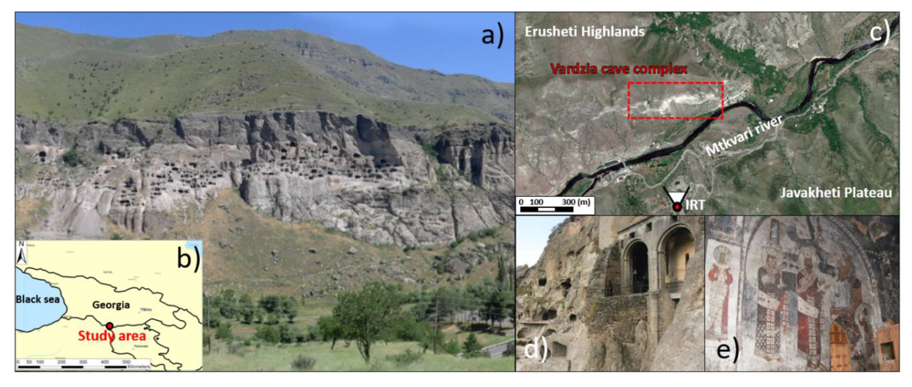
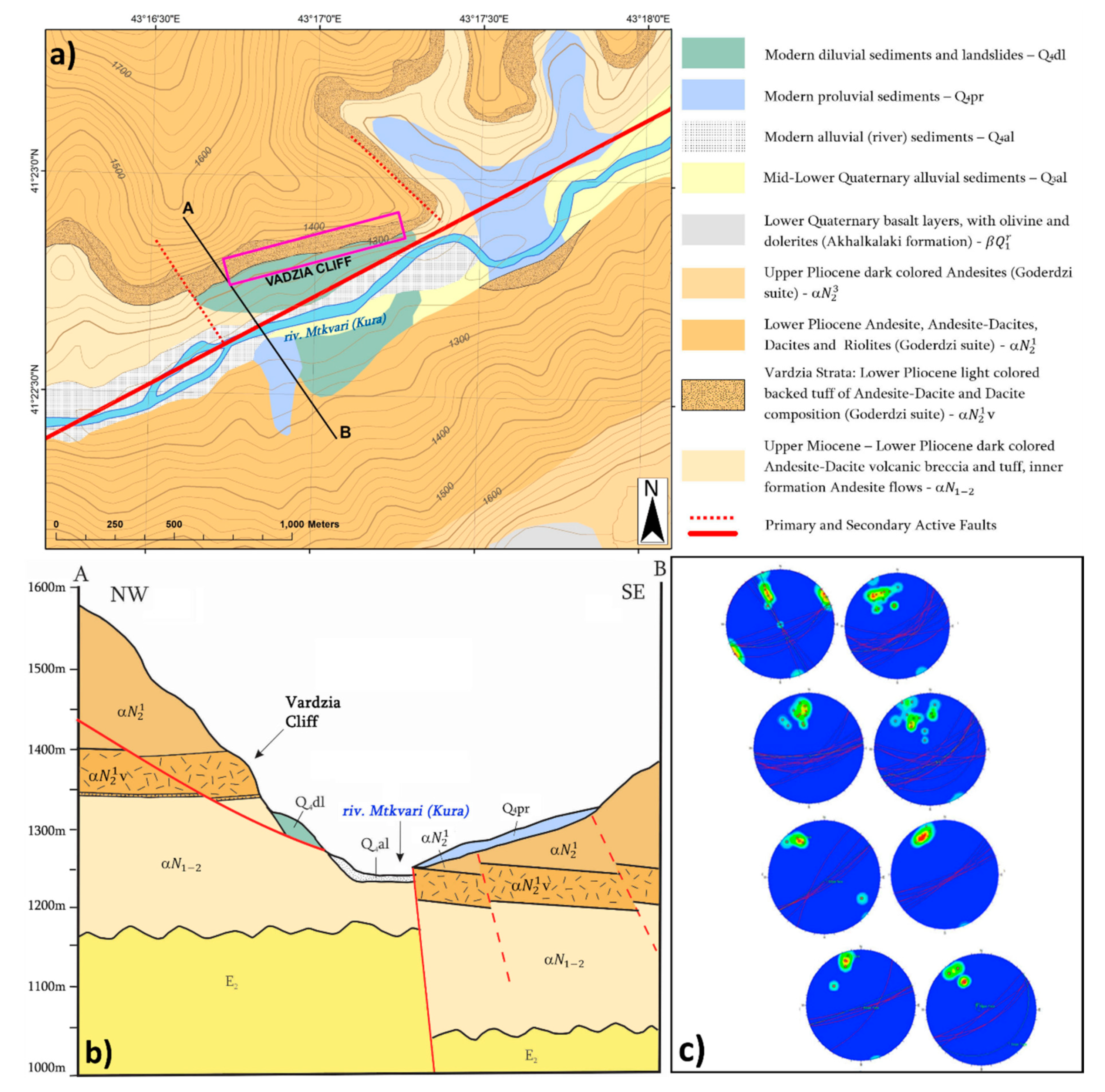
The rock-cut city of Vardzia is located in southwestern Georgia, close to the Armenian-Turkish border, on the left bank of the Mtkhvari river valley (Figure 1a–c). The erosive action of the river and its tributaries has deeply shaped the morphology of the area, deeply cutting the Erusheti highlands to the NW and the Javakheti plateau to the SE, creating a gorge bordered by steep rock cliffs over 200 meters in height (Figure 1c). The site is developed on a sub-vertical rock cliff sector facing southward with an EW direction, with a length of about 800 m and a height of 130 m (Figure 1b), where a large cave system (more than 600 in number on 13 levels) was carved in a thick soft tuff layer [13,21]. Dating back to the second half of the 12th century, the cave city included a complex architectural setting represented by unique architectural features, such as chambers, frescoed chapels, an aqueduct system, subterranean tunnels and vertical connections between the various stories [13]. The earthquake that struck Samstkhe in 1283 AD destroyed about two-thirds of the city cave and the aqueduct system, exposing the majority of the rooms to outside view [22]. The cave complex was largely abandoned after the Ottoman conquest in the 16th century. From a geologic point of view, the study area is located in the Pliocene-Quaternary Samtskhe-Javakheti Volcanic Highland of the Lesser Caucasus [21,22], which is deeply carved by the Mtkvari river gorge. Along with its slopes widely outcrops the Goderdzi Formation, a subaerial volcanogenic-sedimentary sequence composition about 1000 meters in thickness, from Upper Miocene to Lower Pliocene in age, made of volcanic lava-breccias, pyroclastic ignimbrites (tuffs), and ashfall deposits [13,22,23,24] (Figure 2a). This formation can be divided into two sections: (i) upper lava flows (of andesitic, dacitic and rhyodacitic composition with rare occurrence of basaltic rocks), 600–700 m in thickness, (ii) lower pyroclastic deposits 200–250 m in thickness, formed by volcanic breccias and tuffs of different size (from 1 m maximum to millimeter) with andesitic-dacitic composition. The Goderdzi formation is also discordantly covered with thick series of Quaternary age dolerites and basalts of the Akhalkalaki suite [25,26,27,28]. The regional tectonics is characterized by a regional normal fault trending SW-NE along the Mtkvari river gorge, separating the Erusheti block to the west from the Javakheti block and the east [27,28]. The activity of this fault, probably connected with the catastrophic 1283 AD earthquake, is responsible for a 130 m vertical upthrow of the Erusheti block with respect to the Javakheti (Figure 2b).
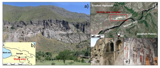
Figure 1.
The rock-cut city of Vardzia (a), Geographic location of the study area (b), the Mtkvari river valley and the Vardzia complex location, including InfraRed Thermography (IRT) camera installation point (c), the monastery complex: arched structures (d), frescoed chapels (e).
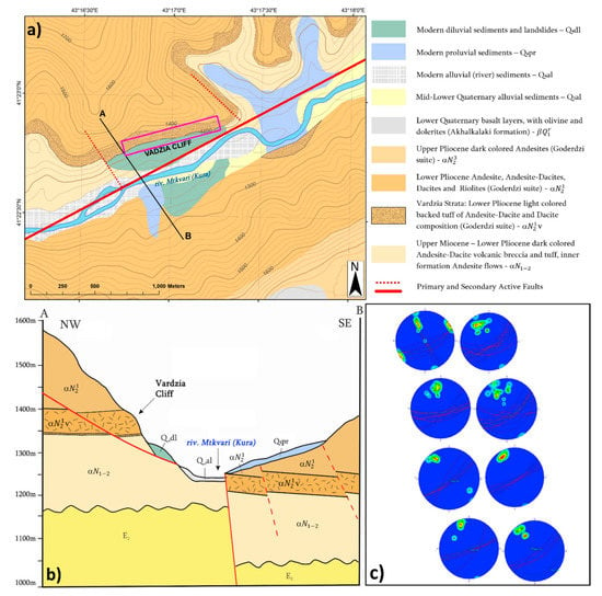
Figure 2.
(a) Vardzia area geological map, (b) schematic cross-section, (c) stereoplot diagrams of discontinuities collected along the rock mass (modified after Margottini et al., 2015).
2. Materials and Methods
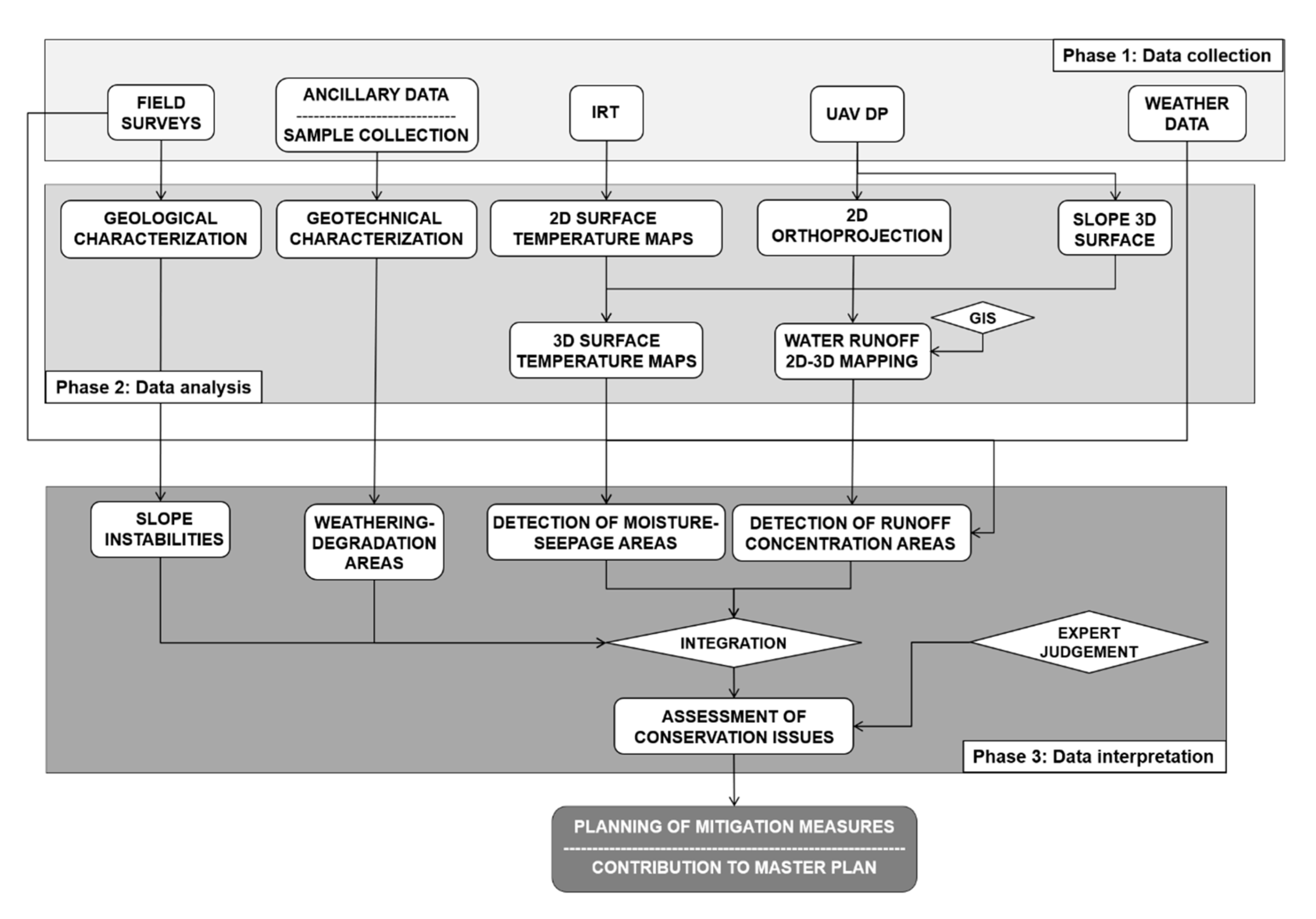
The adopted methodology was implemented according to the following steps (Figure 3). The first phase of data collection involved the gathering of ancillary geological, geostructural and geotechnical data, while field surveys were carried out to validate the RS data interpretation and to collect rock samples (Table 1). IRT and UAV-DP surveys were carried out to collect thermographic and topographic data. Local weather data (rainfall, air temperature, humidity of both air and rock inside the caves) were collected through a weather station and sensors for the correction of IRT data, and to analyze the local microclimate (Figure 4). The second phase of data analysis consisted of laboratory analysis for geotechnical-mineralogical and geotechnical characterization. Furthermore, the analysis of RS data allowed us to obtain high-resolution slope 3D surfaces and 2D-3D surface temperature maps. Water runoff patterns were mapped in a GIS environment. The impact of precipitation acting on the slope surface and the correlation with humidity inside the caves (both in the air and in rocks) was also analyzed on July 9th and 15th, 2017. Specifically, meteorological sensor data were compared with data from rock moisture stations located in the caves along the different rock layers. A final phase of data integration and interpretation provided the detection of potential criticalities with respect to weathering, degradation and slope instability processes.
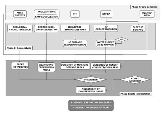
Figure 3.
Work plan of the adopted methodology.

Table 1.
Summary of the data adopted in the study.
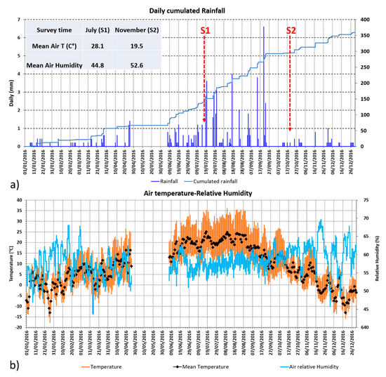
Figure 4.
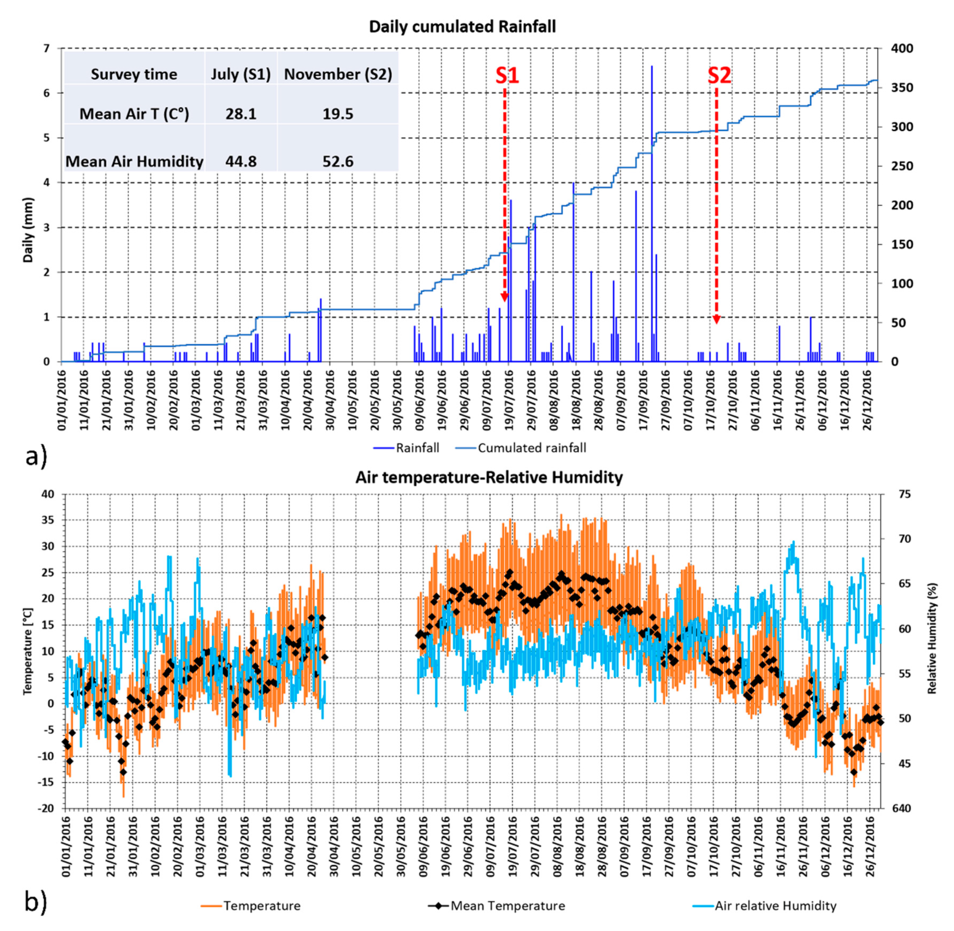
Weather microclimate data recorded by the Weather Station of Vardzia: (a) Daily cumulated rainfall recorded during 2016 in Vardzia and weather conditions during IRT surveys S1 and S2, (b) Air temperature and relative humidity recorded during 2016.
2.1. IRT Surveys
IRT is the branch of remote sensing capable of mapping the pattern evolution of the investigated scenario’s surface temperature, offering non-contact, wide area detection of subsurface defects, to be used as an alternative or complement to conventional inspection technologies in a wide variety of scientific applications [29]. IRT accomplished by using Infrared (IR) calibrated cameras (thermal cameras), whose sensors can detect thermal radiation. The product of an IRT survey is a digital image acquired by the thermal camera array detector (called “thermogram” or “thermographic image”), which following the correction of the sensitive parameters (such as object emissivity, path length, air temperature, and humidity) is converted by the built-in processor in a surface temperature map of the investigated scenario [30]. During the last decades, thanks to the technological development of portable high resolution and cost-effective thermal imaging cameras, InfraRed Thermography (IRT) has been widely used in the field of civil engineering and CH for the detection of structural damage, water seepage, plaster detachments, moisture and surface weathering on different materials (stone, concrete, masonry) [31,32,33,34,35]. In the analysis of slope instability phenomena, IRT can be used for the detection of thermal anomalies which can reveal the presence of potential criticalities such as (i) structural discontinuities, (ii) moisture or a seepage zones, (iii) ledge-niche systems, (iv) lava flows [36,37,38,39,40,41,42,43].
The IRT surveys were performed by using a hand-held thermal camera (FLIR SC620 model [44]), characterized by a focal plane array (FPA) microbolometer sensor with a 640x480 geometric resolution. A built-in 3.2 Mpixel digital camera allowed for the comparison between the thermograms and the corresponding optical images, in order to improve the interpretation of the thermal data. Thermographic image correction, thermal focusing, and mosaicking were performed by means of FLIR Tools+ software [45]. ESRI ArcMap package was used to create classified surface temperature maps using the quantile function [46]. In Vardzia IRT multitemporal surveys were carried out in different seasonal conditions, on 16–17 July 2016 (S1) in a dry period, and 20 October 2016 (S2), following a rainy period (Figure 4). Thermograms were acquired on both surveys when direct sunlight was not hitting the slope (7–8 p.m. in S1 and 4–5 p.m. in S2), therefore during the beginning of the slope face cooling phase, in order to avoid shadowing effects and sun irradiation disturbances. The weather conditions (low wind, cloudy sky) proved to be ideal for the IRT survey, with special regards to the avoidance of the slope shadowing effects during daylight. Various acquiring positions were tested during different times of the day in order to survey the various slope scenario daily irradiation conditions. An optimal acquiring position in terms of geometry and camera field of view was opposite to the slope granting a frontal view, at a 600 m distance from the scenario (Figure 1), providing a 39 cm average pixel resolution. Adjacent thermograms were mosaicked obtaining a 1200 × 560-pixel thermographic image, in order to picture the cliff scenario of 10 Ha.
2.2. DP-UAV Survey and Surface Runoff Modelling
Digital photogrammetry (DP) is a well-established and low-cost technique for acquiring dense 3D geometric information in slopes and from stereoscopic overlaps of photo sequences captured by a calibrated digital camera [12,47]. This technique can provide in a short time high-resolution 2D and 3D surfaces allowing for a detailed and high accuracy representation for the analysis of the geometry-structural setting and surface changes of both ground and structures [48,49].
In the past few years, thanks to the rapid technological development of digital cameras and low cost and small Unmanned Aerial Vehicles (UAV) and Digital Photogrammetry (DP) led to new, promising scenarios in environmental remote sensing and CH applications [50,51,52]. The UAV-DP survey was carried out in the summer of 2017 to obtain a high-resolution orthophoto and a complete 3D digital model of the Vardzia cliff and overlying slope, consisting of a vegetated drainage basin of a 5.5 Ha surface. The images were processed using Agisoft Photoscan [53] and the resulting data implemented in a GIS environment using the ESRI ArcScene package [46]. The retrieved products were high-resolution 2D Orthoprojections and 3D surfaces, both colored in true colors. A surface runoff water modeling was carried out for the analysis of the slope scale drainage system. ArcMap Hydrology Tools package was applied using Flow Direction, Accumulation and Stream Order functions. This allowed us to determine the hydrological network and basins of the slope runoff water and classify water stream order [54].
2.3. Geotechnical and Mineralogical Laboratory Analysis
The geotechnical characterization of volcaniclastic material at the in-situ scale is affected by several issues, such as the large dimensions of the clasts, reduced strength contrast between the matrix and the clasts themselves [55,56], and in fact, studies conducted on volcanic rock joints are very rare. For the above-mentioned reasons, it was not possible to perform some tests on Layer 4. Rock samples were collected by means of core drilling, at depths varying from 30 cm to 6 m (Table 2). The first set of laboratory analyses were aimed at assessing the effect of moisture on the degradation and weathering of the tuff rock. For this purpose, parameters such as density, moisture content, porosity, water absorption, and saturation were retrieved. Furthermore, to obtain information on the effect of water infiltration on the strength of the materials, a number of uniaxial compressions, point load, and Brasilian tests were carried out both in dry and wet conditions following [57] recommendations, to obtain uniaxial compression, tensile strength, and cohesion, respectively. Finally, X-ray analyses were also carried out on rock samples in order to obtain detailed mineralogical information on the clasts and cement material.

Table 2.
Laboratory analyses performed on the collected Vardzia samples.
3. Results
3.1. Local Stratigraphy, Structural Setting and Slope Instabilities
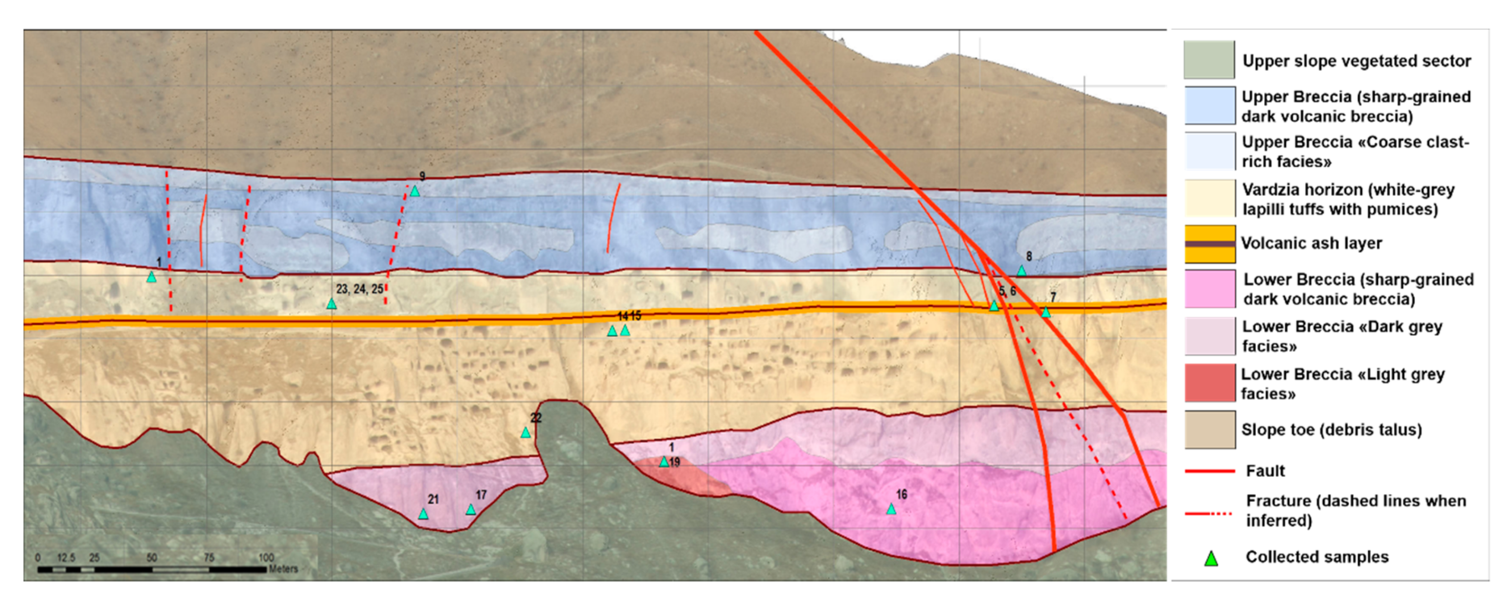
The geology of the Vardzia cliff is characterized by volcanoclastic succession formed by four thick volcaniclastic layers (Figure 5), from bottom to top: (i) “Lower Breccia”=Level 4: a 250 meter thick lower layer consisting of dark-colored lava breccia of andesitic and andeso-dacitic composition, with mainly sharp-grained material (with 3–6 cm clast dimension), predominantly weakly cemented, (ii) a 20 to 80-meter thick layer of light-colored weakly cemented small-grained tuffs, also called in literature “Vardzia horizon” or “Vardzia Ignimbrite”, characterized by felsic, andesitic-dacitic and dacitic composition (Figure 2c) [13,23,24,25,26]. This layer is in terms subdivided into two layers: (ii) a lower level, namely “Grey Tuff”=Level 3, made of 1–3 cm material consisting of lapilli-tuff with dark pumices, scorias and bombs; (ii) an upper level, namely “White Tuff”=Level 2, formed by lapilli-tuff with white pumices, and a thin level of volcanic ash, 0.3–0.6 m in thickness (very soft and highly weathered); (iii) On top of the succession lies the bottom section of the upper Goderzi Formation, here comprised of a sharp-grained dark volcanic breccia layer, namely “Upper Breccia”=Level 1, of andesitic and andesitic-dacitic composition. The upper slope sector and the lower slope talus are characterized by mostly vegetated areas, colluvial deposits, slope debris, and scattered boulders. From a structural point of view, the Vardzia cliff is also influenced by a system of minor faults, mainly orthogonal with respect to the main river fault, bordering the south and north the rock-hewn city complex (Figure 2c, 6) [13]. A low angle fault plane with a 32–350 angle dip towards the river valley is exposed in the cliff’s southern sector. This structure caused the vertical offset of the Vardzia segment of the block in the order of magnitude of 30 meters [24] (Figure 2b). Two main joint systems can be found. A major joint system steeply dipping (70°) towards SE (dip direction 140°–165°) locally parallel to the slope face, formed mainly due to stress release caused by the valley erosion (Figure 2c).
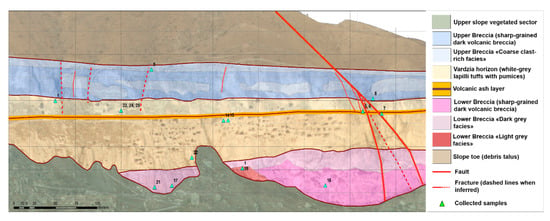
Figure 5.
3D geological map of Vardzia slope (obtained with Unmanned Aerial Vehicle (UAV)-based Digital Photogrammetry (DP) 3D surface).
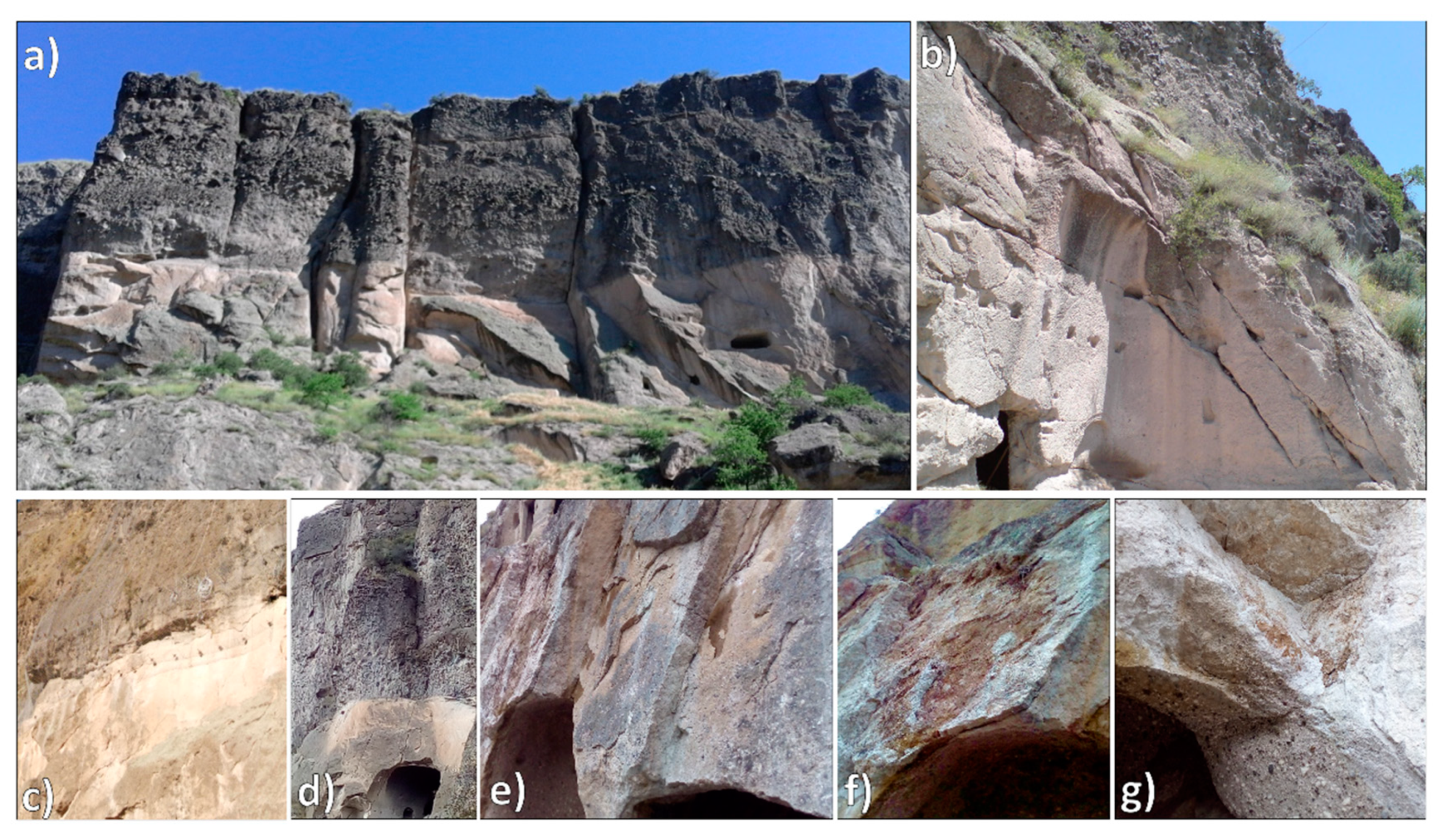
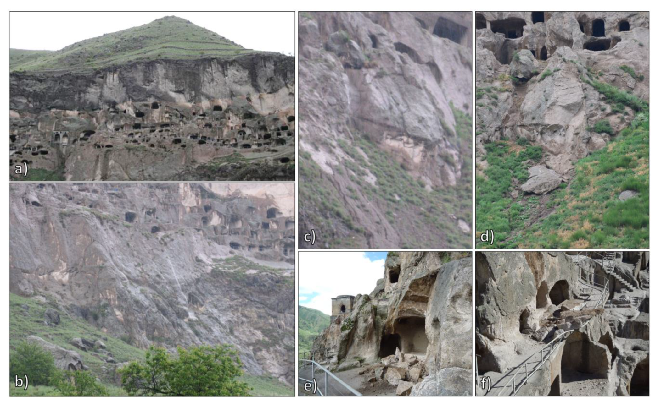
A second system with sub-vertical geometry, intersecting orthogonally the former, connected to cooling of the volcaniclastic sequence [13]. Given the slope geometry and the discontinuity orientation the following instability mechanisms can be recognized [58,59,60,61]: rockfall and topples at the contact between Level 1 and 2 (Figure 6b,c), planar failures along weathered discontinuities parallel to the slope (Figure 6e–f) and wedge failures (Figure 6g), mainly in Level 2, secondarily in Level 3, and a large roto-translational rock slide involving Layers 1, 2, and 3, falls and topples in Level 4 [13,15,16,17,18]. Blocks of various sizes are still present at the slope toe (Figure 1a, 5), showing the recurrence of this phenomenon [13,58].
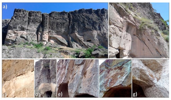
Figure 6.
Vardzia slope structural setting and slope instabilities: subveritcal joint set (a), planar failure (b) direct fall (a) and topple (c) along the contact between Upper breccia and White Tuffs. White Tuffs: weathered surfaces in correspondence of planar failures (e–f: high-angle joint set parallel to the slope) and wedge failures (g).
3.2. Geotechnical and Mineralogical Analysis
The laboratory analysis of the samples showed general high values of primary porosity for the four analyzed layers (16 < n < 29), while the higher values correspond to the tuff layers (with special regards to Layer 3) (Table 2). Rock moisture shows higher values in the tuff layers (up to 3.6 in Layer 2 and 3.5 in Layer 3, respectively), while in the Breccia layers it ranges from 0.6 to 2.6. All these values decrease with depth (see samples 23-24-25), showing the action of water infiltration on the weathering from the slope surface. On the contrary, the density increases in-depth, as rock gets less weathered. Tuff layers show also higher water absorption and saturation with respect to the breccia layers. For Layer 2 the uniaxial compressive strength (UCS) is equal to 9.3 MPa in dry conditions and 2.6 MPa in wet conditions, indicating again a strong influence of water content on the material response. A similar effect was detected for the tensile strength σt estimated by the Brasilian tests, which was equal to 925 kPa in dry conditions and 300 kPa in wet conditions. Layer 3 subjected to the same tests, is characterized by very similar physical and mechanical properties. The properties of Layer 1 were investigated by a limited number of tests: point load tests gave an average UCS value of 14.8 MPa in dry conditions (the tensile strength σt was assumed to equal to one-tenth the uniaxial compressive strength UCS). The corresponding values of the cohesion for dry and wet conditions were then calculated from the corresponding UCS values. According to the X-ray diffraction analysis results, the main primary minerals of the rocks are Plagioclase (andesine-Labradorite), amphibole (Hornblend), mica (Biotite), a rare occurrence of quartz and calcite. Rock building minerals are cemented by an amorphous phase (volcanic glass). Ca-montmorillonite, occurring in various quantities in all the samples of Vardzia complex rocks, is mainly a product of volcanic glass alteration, while its quantity is determined by the intensity of the alteration process.
3.3. Microclimate Data Analysis
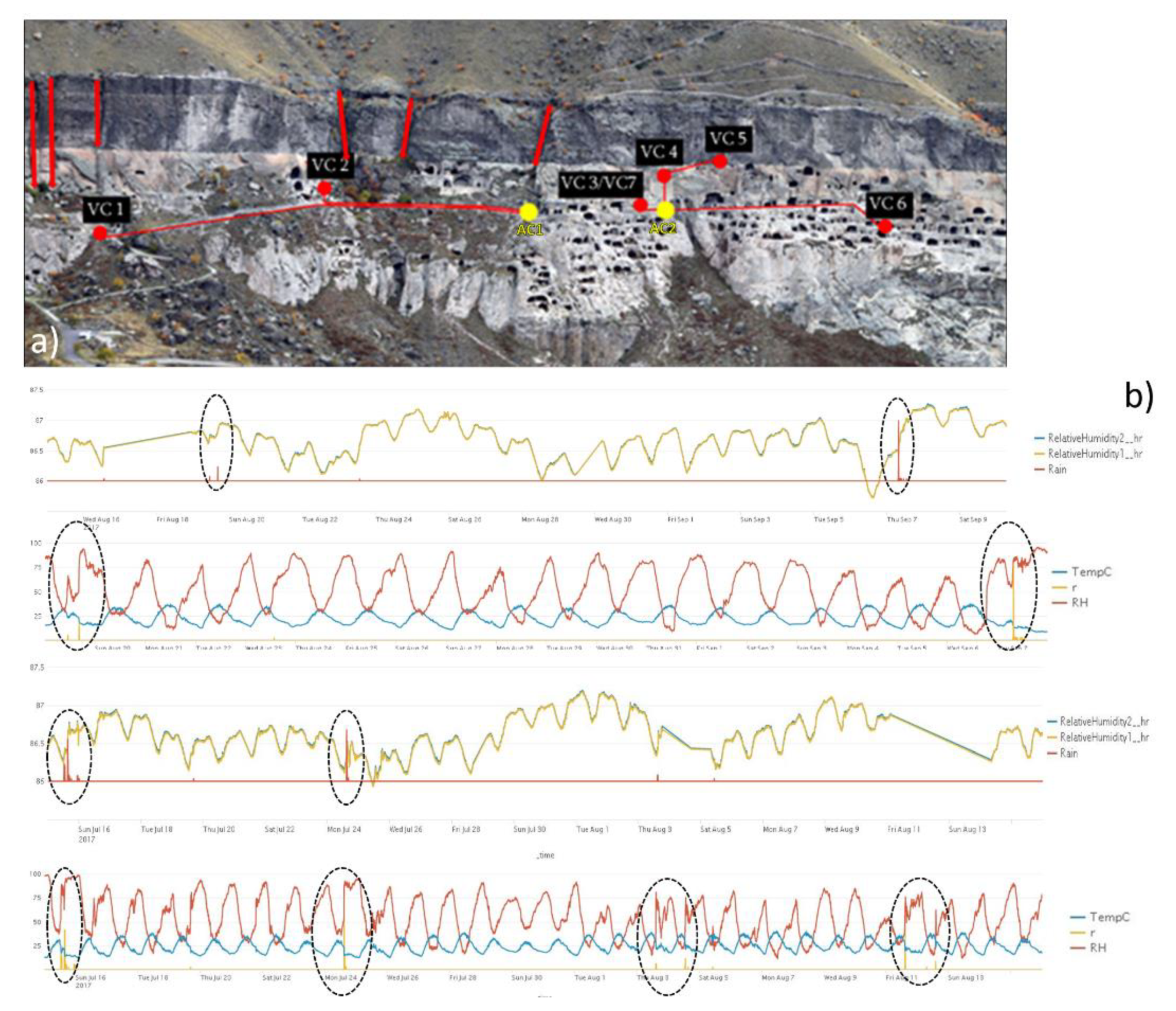
Several rain events were selected and analyzed: the criteria for selecting the rain events were time between two of the events and quantity of precipitation. Time between the rain events was considered favorably to be maximum for minimizing the influence of previous rainfalls. Due to the large amount of data, a special algorithm was developed in the Python environment in order to process the data and construct graphs of precipitation in correspondence to the monitored caves (the example of VC4 station is shown in Figure 7). Visual correlation of pikes in rock humidity with rain dates allowed us to estimate the average time periods needed for rainwater to be converted into rock humidity at different levels and depths of Vardzia rock (black dashed ovals in Figure 7). The results of the analysis among all the cave stations clearly shows the difference between the upper breccia (Layer 1), and the lower tuff level (Layer 2): VC6 and VC2 monitoring locations show more than 2 weeks needed for rainwater infiltration, While VC5 and VC located closer to the top of Vardzia require only 4–6 days intervals (Table 3).
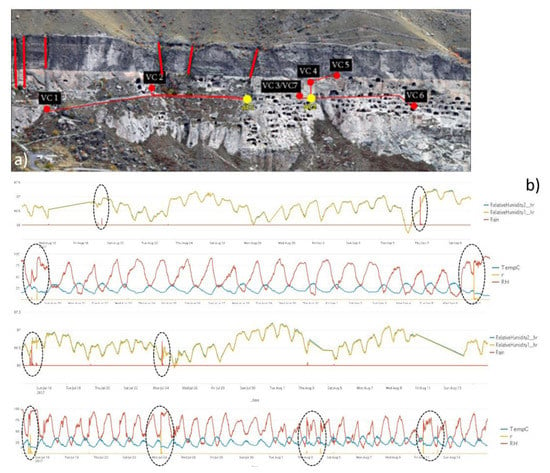
Figure 7.
(a) Moisture stations, (b) VC4 Microclimate observation station data.

Table 3.
Elevations of monitoring points and depths from rock surface vs rainwater infiltration time intervals.
3.4. Remote Sensing Analysis
3.4.1. IRT
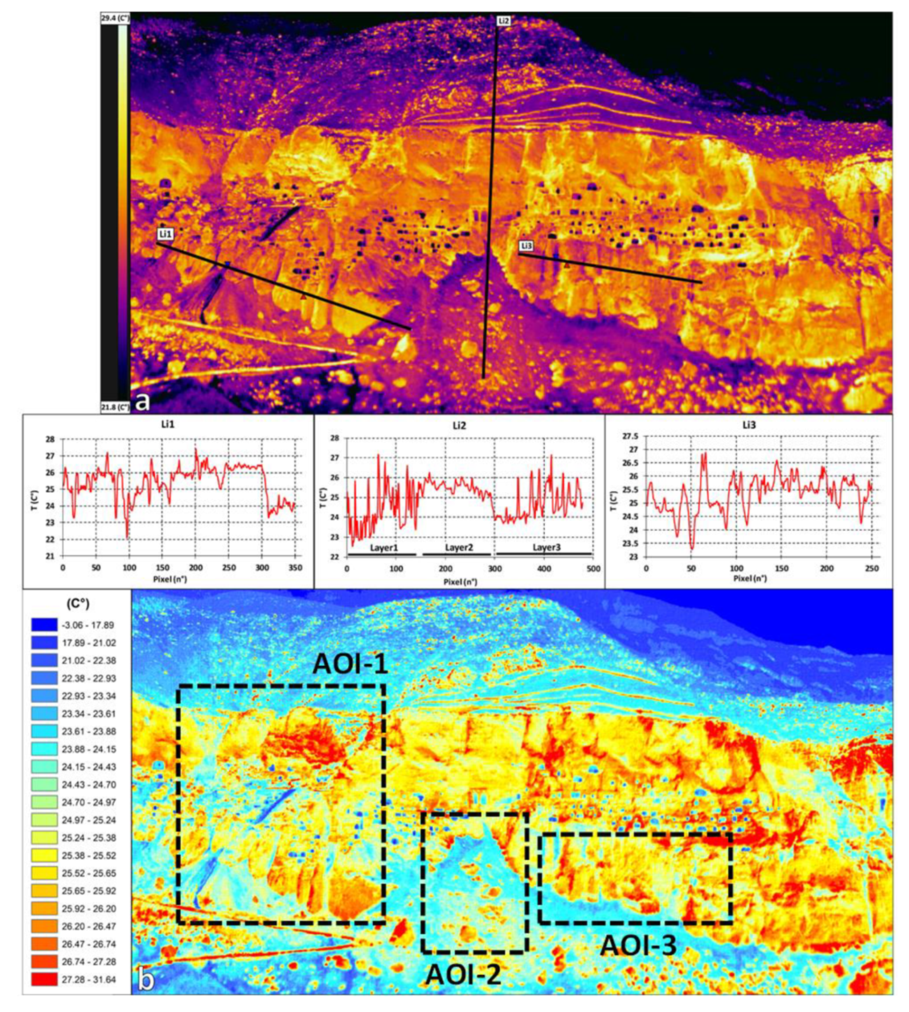
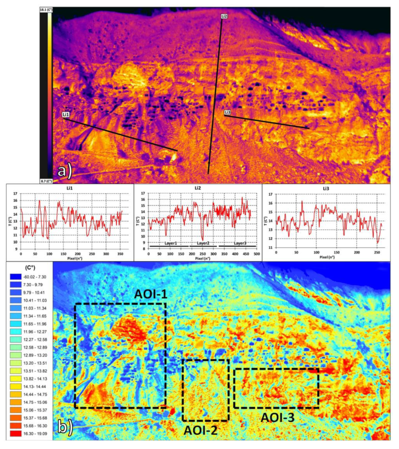
From a general point of view, the IRT data (Figure 8 and Figure 9) during both surveys show lower surface temperatures in the upper slope sector, due to its widespread vegetation cover (mean values: 23.2 C° during S1 and 11.1 C° during S2, Table 4).
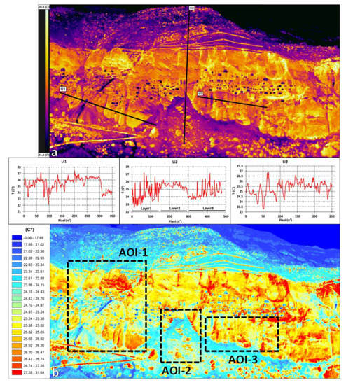
Figure 8.
IRT data acquired in S1: (a) Mosaicked thermograms acquired on 16 July 2016 at 19:00, including surface temperature profiles Li1-3, (b) corresponding classified image.
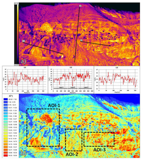
Figure 9.
IRT data acquired in S2: (a) Mosaicked thermograms acquired on November 20th at 18:40, including ST profiles Li1-3, (b) corresponding classified image. Corresponding visible image (c).

Table 4.
SST values measured in the various slope sectors.
Some minor warm temperature anomalies are measured in correspondence to the scattered boulders of the Upper Breccia (up to 29.4 C° during S1, and 14.7 C° in S2 respectively), which have been isolated from the surrounding finer matrix due to differential erosion. Another widespread vegetated sector is represented by the slope toe, showing slightly higher mean ST values with respect to the upper slope (mean values: 24.1 C° during S1 and 13.4 C° in S2). Warm temperature anomalies were also here detected (up to 29.7 C° during S1 and 17.9 C°), due to the presence of fallen block deposits connected to the instability of the rock cliff face. The latter exposed rock slope cliff shows the higher ST values of the scenario (mean ST of 27.8 C° during S1 and 14.1 C° in S2), although several cold thermal anomalies are present.
Based on their pattern, location and interpretation of the visible images these can be described as follows: the cave system carved in Level 2 and 3 (mean values of 21.1 C° during S1 and 8.9 in S2), vegetated sectors located on both the eastern and western edges (22 C° mean ST value during S1 and 9.6 in S2), and high-angle linear-like sub-vertical anomalies intersecting (21.6 C° mean ST value during S1 and 10.2 in S2). These latter in particular were detected in both surveys in correspondence to open decametric persistent sub-vertical fracture system orthogonal to the cliff face intersecting mainly all of the layers (Area of Interest AOI-1), while only in the cliff eastern sectors starting from Layer 1 down to Layer 4 (AOI-2) (see profile Li1-Li2 in Figure 8a and Figure 9a). Considering their pattern and the continuous rainfall occurring before both surveys, they were interpreted as areas that are connected to the presence of moisture. In particular, the sharper of these anomalies within AOI-1 is connected to a water pipe seepage, which was used for excavating purposes by the local group of archeologists. More cold thermal anomalies are also located within the slope toe sector (AOI-2-3): they are localized mostly along the contact with the cliff face, showing moisture sectors within the top sector of the debris talus. Others have a vertical linear pattern and are due to minor rivulets.
3.4.2. UAV-DP
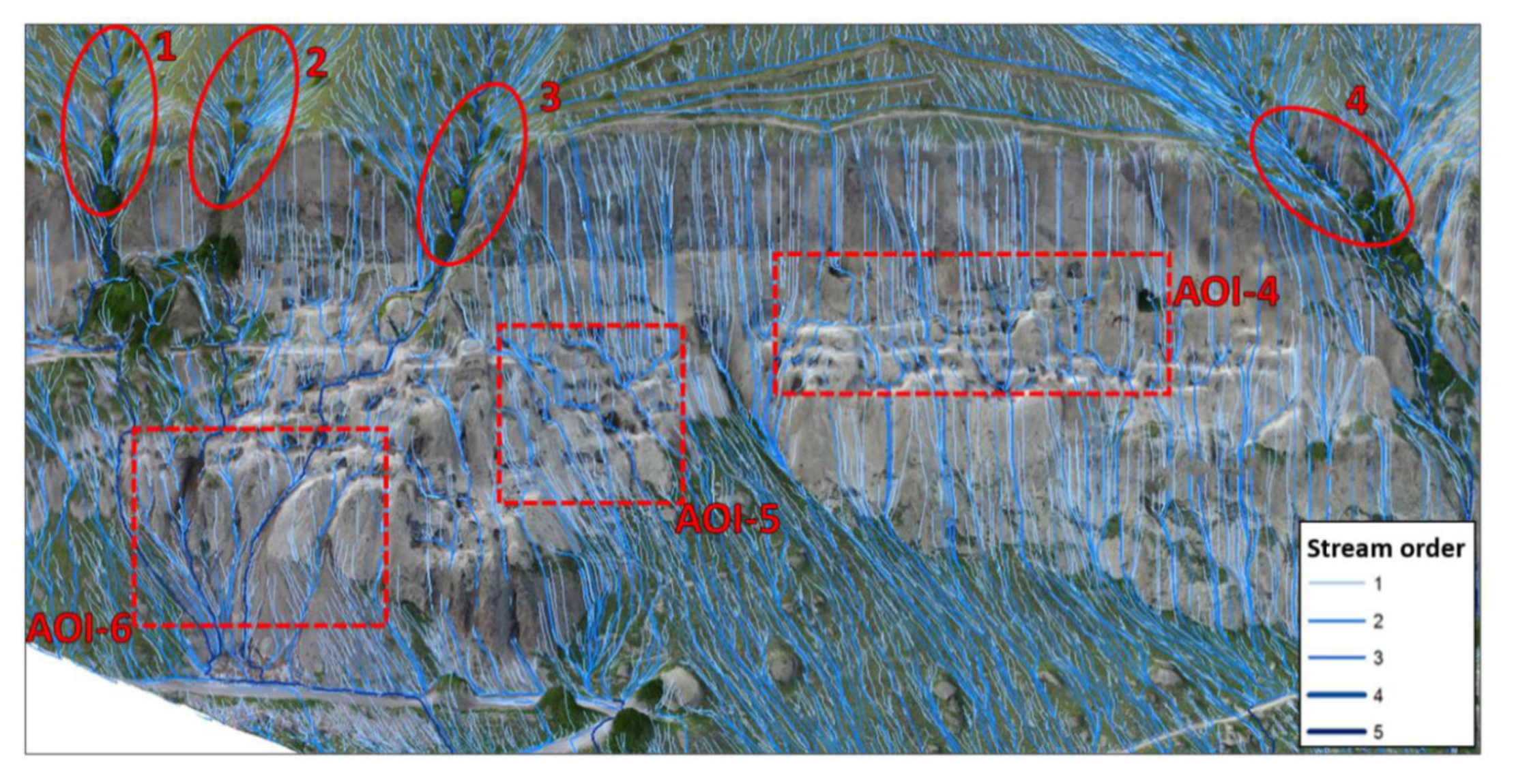
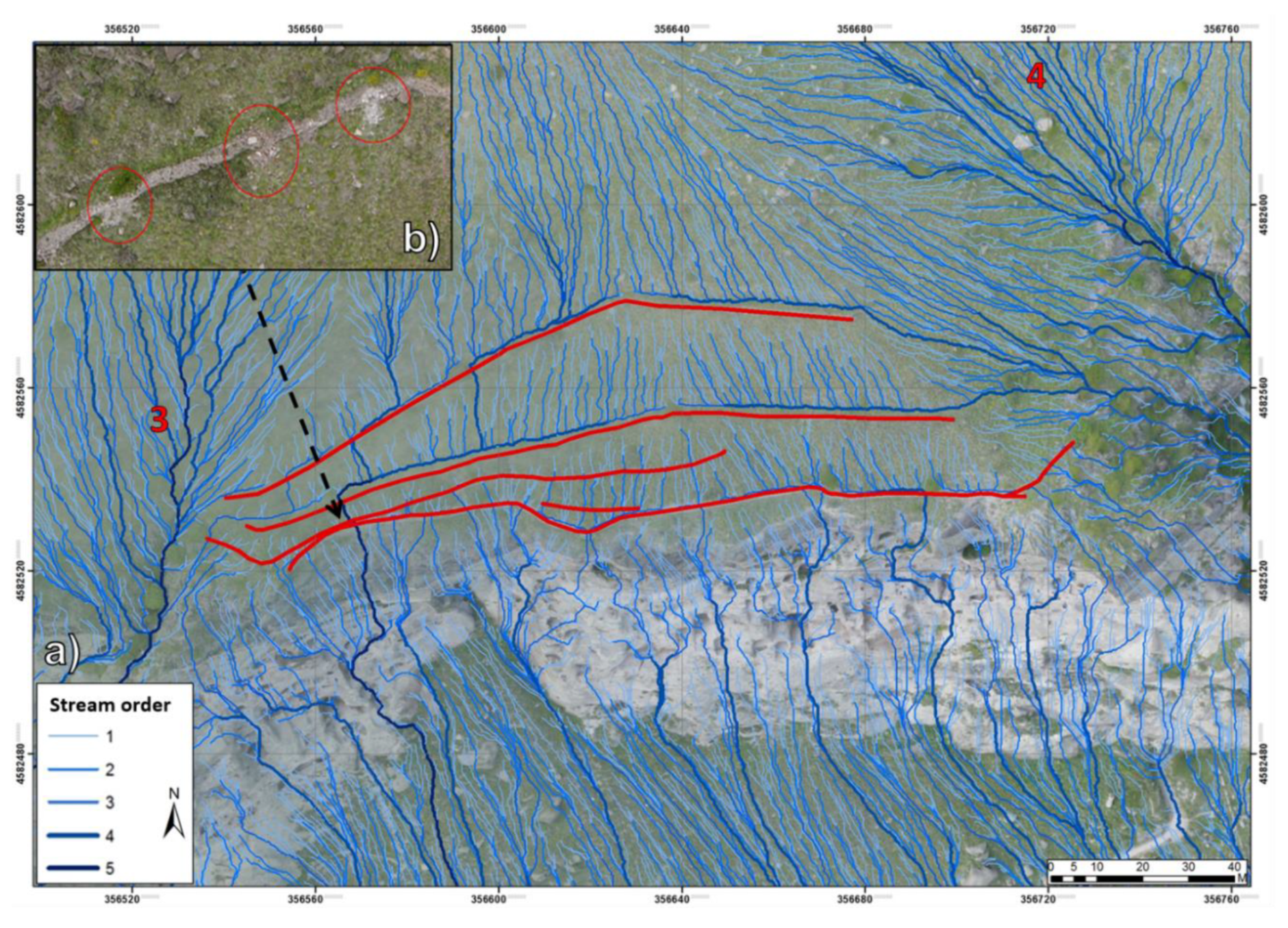
The Hydromodelling analysis allowed us to map the spatial distribution of water runoff within the monastery complex of Vardzia. Streams were categorized by order and catchments were identified, as well as areas of concentration (Figure 10 and Figure 11). The 3D model provides a clear frontal view of the water runoff patterns on the cliff face and the slope toe (Figure 10). Four areas of water concentration are visible at slope break between upper slope and cliff: these act as main areas of water runoff concentration, acting as areas of enhanced linear erosion, especially in correspondence to Layer 1. In the middle-lower cliff sector, the slope morpho-structural setting creates three other areas of interest with respect to water concentration: (i) AOI 4, localized between Layer 2 and 3, (ii) AO5 and AO6 at the contact between Layer 3–4 and the slope toe. Results of the 2D orthoprojection show three main catchments on the eastern sector (Streams 1–2 and 3) and one located at the western edge of the complex (Stream 4), all of them showing streams up to the fifth order (Figure 11). In the central section, it is possible to observe the effect of the water-diverting structures, constituted by a runnel-retaining wall-system (red lines in Figure 11). These were built as part of the preliminary management plan, for the double purpose of preventing site runoff and erosion, as well as mitigating the risk of rock falls, due to the presence of potentially unstable scattered rock boulders on the slope’s topmost sector. The runnels effectively channelize minor streams towards the two adjacent main order catchments to the west and the east, although in some sectors they have been damaged by the impact of some detached boulders, therefore in some points water flows directly along the slope.
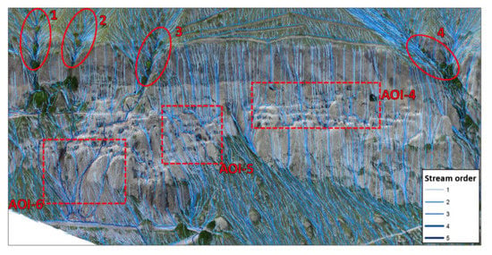
Figure 10.
Front view of the modeled drainage network on the Vardzia slope 3D surface.
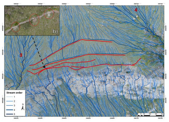
Figure 11.
UAV-DP products: (a) 2D Orthoprojection of Vardzia’s hydrographic network on the Upper slope sector and cliff face, (b) detail of runnel-retaining wall sector impacted by boulders.
3.4.3. RS Data Integration and Field Validation
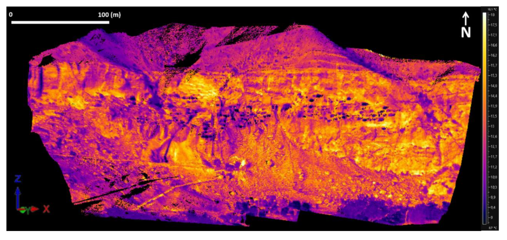
ST data was merged with the slope 3D surface, allowing to refine the slope drainage pattern interpretation and an accurate georeferencing of the detected cold thermal anomalies.
Moisture sectors are localized within the main open cracks. This confirmed the relationship between the localized AOI: water runoff and moisture are concentrated in the slope western sector, where water-diverting structures are absent and stream erosion has deeply cut the volcanic breccia and part of the tuff (AOI 1 and 5) (Figure 10, Figure 11 and Figure 12).
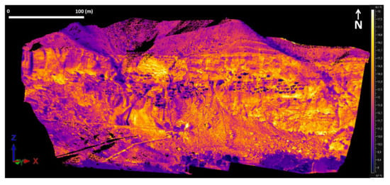
Figure 12.
Mosaicked 3D surface temperature maps of the Vardzia monastery, obtained by merging the single thermograms with the UAV-DP slope surface.
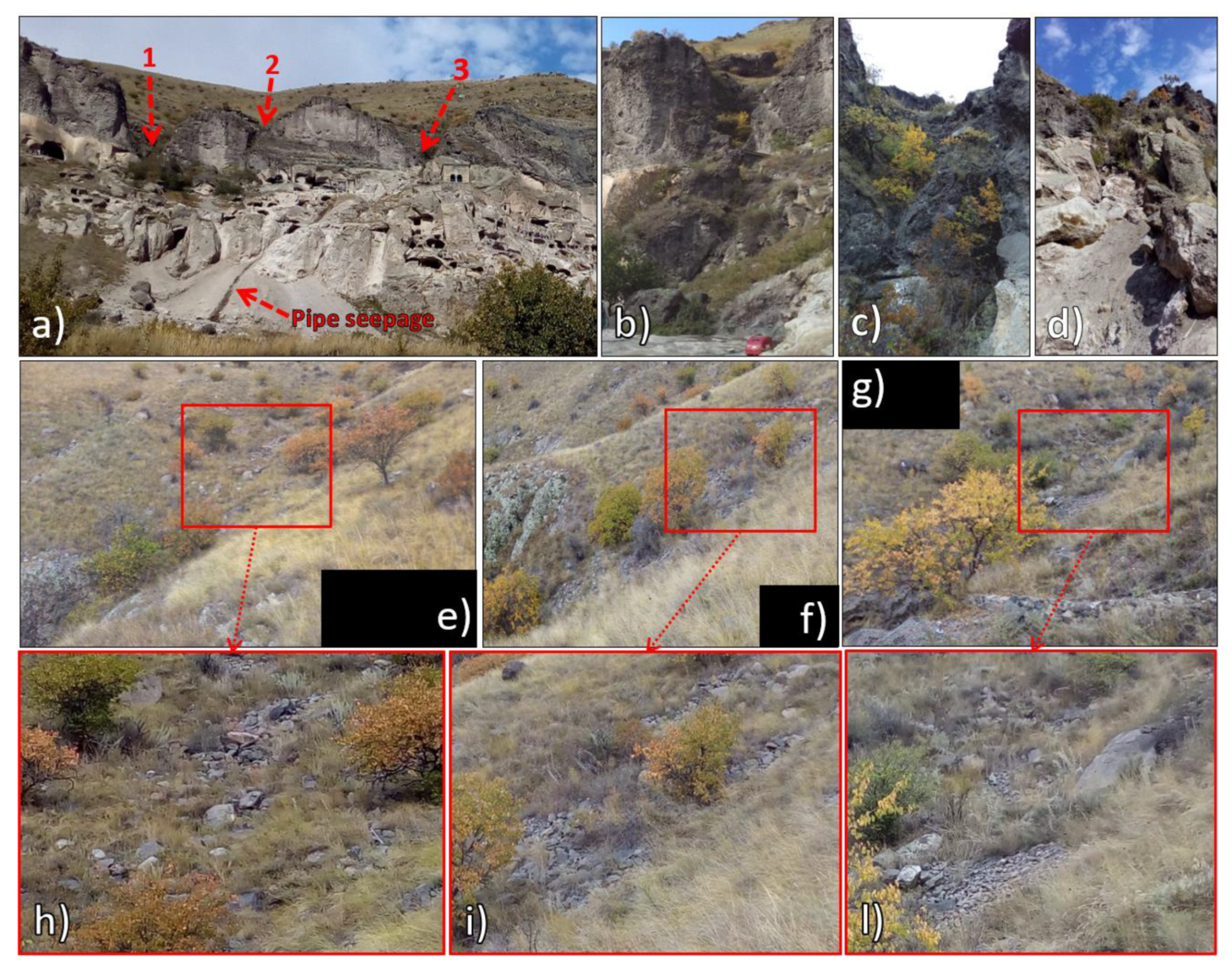
These structures, despite the damage in some sectors, prove to be effective in protecting the upper slope face from the main runoff pattern. Nevertheless, the lower slope face and slope toe, being less steep, are still affected by direct runoff, as shown by AOI2-5. Field inspections in the upper slope basins of Streams 1–3 revealed the presence of intensively vegetated sectors and deep rock cuts filled with coarse slope-debris, proving the action of water-sediment transport due to an ephemeral stream network (Figure 13). Rill erosion features were also detected on the vegetation cover of the debris taluses within the slope-toe.
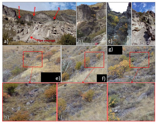
Figure 13.
Field evidence of water erosion-sediment transport: (a) bottom view of the main streams (1-2-3), rock slope cuts of the Stream 1 (b), 2 (c) and 3 (d), view of the erosional–transport features in the slope brake between upper slope and cliff face Stream 1 (e–h), 2 (f–i) and 3 (g–l).
4. Discussion
4.1. Instability Processes and Weathering Problems in Tuff Slopes
From a geological point of view, tuffs represent thick sequences of volcanoclastic rocks formed by overlapping layers of volcanic ash, lapilli-to-bombs pumice/scoriae, and rock fragments, rapidly cooling after volcanic eruptions [62,63,64]. These layers are characterized by a highly heterogeneous rock fabric, represented by a weakly welded angular matrix with grain size ranging from fine ash (clay-size) up to lapilli (sand-size), in which crystals or rock fragments up to gravel and block-sized lithics can be embedded [65,66]. From a geotechnical point of view, the arrangement between these tuff components, their different fabric and the normally large amounts of clay minerals in the matrix opens a very wide spectrum of porosities, which in terms plays a very important role in the behavior of the rock resistance to weathering and deterioration due to moisture [66,67]. Moisture expansion under determinate relative humidity (hygric dilatation) is caused by the swelling and shrinking of clay minerals (mainly derived from the ash matrix alteration), and is clearly recognized as one of the most important factors contributing both to the weathering and deterioration of this material [68,69,70,71]. On exposed tuff slope surfaces areas of preferential water concentration are governed by the slope morpho-structural setting, being caused by the combination of the fracture system, and the slope-scale morphology-roughness (e.g., ledges and niches and unstable protruding-overhanging sectors). Joints and cracks, in particular, can also control the structural stability of tuff slopes [71,72,73] since their geometry with respect to the slope face generates different kinematic behavior of the rock mass, while their engineering properties are adversely affected by water seepage and moisture, which causes weathering and discoloration films reducing the wall strength. Chemical weathering, in particular, leads to the eventual decomposition of silicate minerals to clay minerals. This process can lead to the loosening of the rock mass and the widening of the joints creating potential instabilities such as open features [74]. Moisture expansion can also lead to the reduction of the uniaxial compressive strength of the tuff when saturated [18,72]. In this context the pervasive fracture networks due to cooling of tuff rock slopes represent a further drawback of this material, being areas of preferential rainfall infiltration and seepage as well as a major cause of structural instability [72,75]. Furthermore, the combination of degradation/erosional processes acting on the exposed surface of the tuff gradually reduces the wall thickness of the hewn monuments [73], and the strength reduction of both rock slope and discontinuities due to saturation can create serious stability and conservation issues.
4.2. Contribution of RS Techniques for Detection of Criticalities in Vardzia
IRT, given the portability and the fast acquisition and processing times of thermographic data, can be profitably applied for mapping criticalities in the field of tangible CH conservation [76,77,78]. In Vardzia the obtained ST maps allowed to map the moisture sectors in correspondence to the large sub-vertical open fractures orthogonal to the valley, and where the main streams cut the whole breccia level. In particular, moisture proves that the drainage pattern concentrates within the sub-vertical joint system affecting mostly Layer 1-4 in AOI1 and Layer 3-4 in AOI2. Rill erosion particularly affects the slope toe debris talus AO3. Since these areas are connected to rainfall, as shown by the weather data (Figure 5 and Figure 7), they were interpreted as ephemeral rivulets. The hydro-modeling analysis on the UAV-DP and TLS products provided the accurate mapping of the overall analyzed slope area’s drainage pattern, for a better understanding of water runoff and infiltration. These latter represent widespread areas of surface erosion and weathering features and occur mainly in correspondence to Layer 2 and 3 (AOI 4-6). They are due to the interaction with the morpho-structural setting of the slope, which is able to generate differential erosion in the different volcaniclastic layers, up to moderate mass transport and gravitational phenomena with deposition at the slope toe, creating also small debris taluses linking the slope toe to the alluvial plain. UAV-DP provided a high-resolution 3D slope surface on which high-resolution modeling of the drainage network was performed. Stream network up to the 5th order was mapped from the upper slope to the slope toe, enhancing the presence of four main creek catchments located on the western sector (1–3), and one to the eastern limit of the complex (4). The monastery slope eastern sector is less affected by the presence of ephemeral creeks, due to the slope conformation and the presence of a runnels-retaining wall system (Figure 11). These are built with the material coming from the upper slope scattered blocks, partly mitigating the rockfall risk. Nonetheless, the 2D hydro-modeling was very useful for checking the efficiency of these structures: in fact, it was possible to see that they are damaged in some sectors due to past rock boulder impacts. In the planning of an IRT survey, given the possible logistical limitations, the timing of the survey and the position of the thermal camera acquiring point must be carefully considered in order to obtain both the best image resolution, the wider field of view of the investigated scenario, and to avoid as much as possible the negative effects to the interaction between the slope aspect with respect to solar illumination. IRT alone is insufficient for a complete landslide analysis: in order to obtain a more accurate interpretation of the results, therefore it can be more effectively used as an ancillary low-cost technique, through integration with other ground-based remote sensing geodetic techniques, especially regarding DP or lidar. Future developments should include the application of fixed thermal camera installations in a landslide remote surveying-monitoring station, for gathering continuous, high-resolution, real-time thermographic data. In all of these perspectives, a skilled thermal camera operator is strongly recommended for correct IRT image acquisition, elaboration and interpretation procedures. Finally, the digital data collected and elaborated in various steps of the project, starting from the topographic survey of the site (e.g., UAV-DP), can provide a set of materials suitable to be used for other purposes such as tourism exploitation, offering basic data for virtual tours, panoramas, etc. (e.g., https://zamaniproject.org/). In the meantime, available digital data even if more complex as in the case of IRT or monitoring sensors, can offer valuable support to demonstrate the efficacy of conservation projects to decision-makers as well as to show the general public the achieved results [79]. Another important issue is the availability and the low-cost of the digital cameras used for the DTM creation. This can suggest the need for a proper capacity building for both field survey and desk interpretation. On the other side, since the date should be used by stakeholders, very often not familiar with advanced technology, there is a need to develop specific end-user interfaces, allowing data visualization and some analysis, without affecting the internal consistency of the information. A clear example of this is the EU project PROTHEGO [80] and other case studies [81], where advanced ground deformation data obtained from satellite imaging can be provided to end-user for the interpretation of geological phenomena.
4.3. Risk Mitigation Strategy in Vardzia
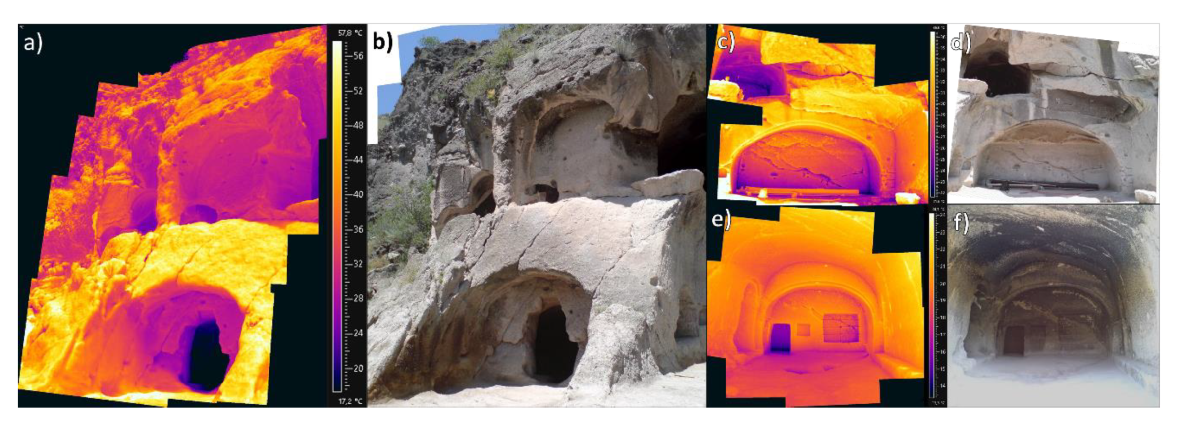
The stratigraphic position and the geomechanical properties of the volcanic breccia (Layer 1) play an important role in the current geological structure of the complex: located on top of the tuffs, their higher density and hardness have protected the lower, soft and weak tuffs from erosion. Nevertheless, this layer is currently being deeply undermined by stream erosion, with special regards to the western slope sector. In Layers 2 and 3, the mineralogical analysis showed the widespread presence of clay minerals such as Ca-montmorillonite, formed by the chemical weathering of the volcanic glass which constitutes the tuff cement. This is responsible for the fast surface chemical weathering of the rock mass. The sub-vertical and high-angle dipping joints intersect the horizontal bedding of the volcanoclastic units along the entire Vardzia cliff, causing several instability phenomena whose type, dimension, and kinematics depend on local orientation, mechanical properties of volcaniclastic layers, spacing and persistence of joints [15,16,17,56,57] (Figure 6). Moreover, moisture expansion due to water runoff and concentration further exacerbates this scenario. Therefore, water flow and infiltration were assessed as one of the most important predisposing factors of slope instability in the site of Vardzia, since it negatively affects the material’s geotechnical properties and the strength of discontinuities [72] (Figure 14). This is extensively proved by the geotechnical data: rock moisture decreases by depth, demonstrating the effectiveness of water infiltration from the surface, while the density increases, as the rock, is less weathered in depth (Table 2). At the same time, Water Absorption and Saturation is also higher on the surface in the weathered part of the rock. As an additional proof, the cohesion and resistance of the rock layers, in terms of uniaxial compressive and tensile strength, also decreases in wet conditions. The microclimate data confirm this scenario, as water infiltration affects the relative humidity within the rock layers more effectively from the top (Layer 1, VC5) to the lower Layer 3 (VC6) (Figure 7–Table 3). The strong alteration of the clayey mineral cement is also responsible for the strong reduction of the strength of both the rock and the discontinuities (especially the system parallel to the slope). As a matter of fact, the excavated caves are highly critical slope sectors that experience fast surface deterioration, raveling, and spalling (Figure 15) [13,56]. The significant reduction in the strength of the tuff due to moisture, poor to very poor durability, and the adverse effects of joints on the structural stability need to be considered during future management activities. This is proved by the recorded rock collapses in recent years (Figure 16).
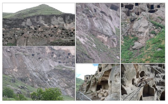
Figure 14.
Conservation criticalities due to water runoff-infiltration: intense water runoff during a rainfall event in 23 May 2014 on the slope face (a) and slope toe (b) (courtesy of the director of the site), detail of collapsed block in AOI5 (c: before the collapse – photo taken on 25 May 2015) and after the collapse (d). Details of rock collapses occurred after rainfall events: 11 July 2016 (e) and 19 September 2016 (f).
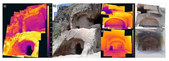
Figure 15.
Close-ups of the criticalities in the cave systems acquired on S1: Mosaicked thermogram (a) and correspondent photo (b) of cave system characterized by persistent and spaced fracture system, mosaicked thermograms of intensively fractured cave system (c) with correspondent photo (d), mosaicked thermogram of single cave (e) and correspondent photo (f) characterized by spalling of the rock surface in the roof of the room, controlled by rock weathering and stress degradation.
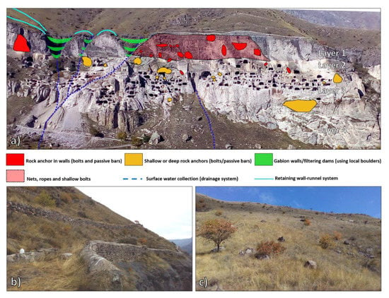
Figure 16.
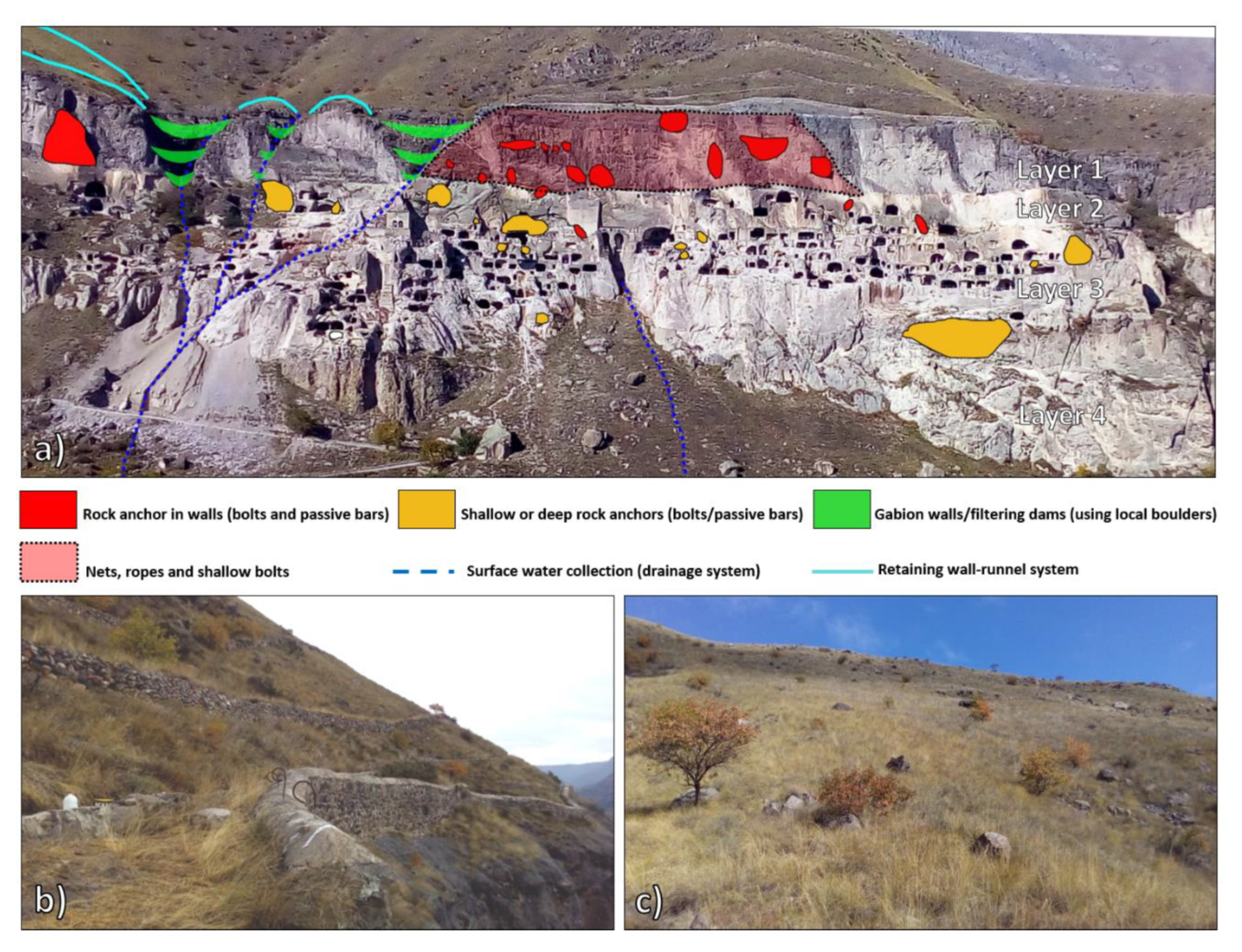
(a) Contribution to the General Master Plan of the proposed mitigation measures for the whole Vardzia Monastery: system of surface water collection and runnel-retaining walls built along the monastery slope rock wall upper sector (modified after [17]), sectors characterized by instability on the rock cliff with related anchor type, (b) Water draining structures in Vardzia formed by the runnel-retaining wall system, (c) detail of scattered boulder of the upper slope sector.
Thus, the moisture of any kind should be avoided in and around the rock-hewn structures. For this purpose, a new low-cost/impact system of runnel-retaining walls, as well as filtering weirs within the creek bedrock cuts, should be designed and implemented also in the western slope sector, by using the scattered boulders for construction material (Figure 16b). Cliff instability mitigation measures usually require the use of either structural or non-structural measures or a combination of both. Structural measures imply intensive earthwork and the construction of concrete structures and may be visually invasive.
The design of the stabilization and protection works of the Vardzia cliff has the challenge of reconciling the safety and conservation of the site with sustainability and visual integration [17]. Surface reinforcement techniques can be used to prevent small size rock wedges and blocks from causing rockfalls. These aim at providing surface reinforcement and restrict the loosening of the rock mass, and can give the advantage of being low-visually intrusive and can be usually combined with nails or rock bolts to fix them to the rock surface.
5. Conclusions
The applied methodology was profitably applied for the detection of conservation criticalities affecting the rupestrian monastery complex of Vardzia. These are governed by the lithological, morphological, structural and geotechnical characteristics of the lava breccias and tuffs constituting the volcaniclastic slope in which the rock city was carved. The laboratory and weather data analysis provided insights on the problems caused by moisture on the acting weathering-degradation and instability processes affecting the monastery cliff. RS techniques proved to be a feasible solution to achieve reliable data, providing the detection of slope criticalities on a large scale, also in inaccessible-hazardous sectors, while granting the safety of operators. Field surveys confirmed the processes of water runoff, weathering, and degradation acting at the various sectors of the slope, especially in correspondence of Layer 1 and 2. IRT, thanks to the favorable thermal camera field of view and the southern orientation of the slope face proved to be a useful tool for the rapid multi-temporal mapping of the whole monastery complex, with special regards to the detection of areas more subject to weathering (moisture zones connected to the ephemeral drainage network).
UAV-DP high resolution surfaces granted the coverage of the entire slope, with special regards to the upper sector, and allowed the hydro-modeling analysis to provide the mapping of an ephemeral stream/rivulet network up to the 5th order, confirming the insights of IRT. The so-detected ephemeral streams pattern is connected to rainfall and is governed by the interaction of water runoff with the morpho-structural setting of the slope. Microclimate data and laboratory analysis proved that surface runoff and moisture areas located in correspondence of these streams are a primary factor of weathering and degradation of the site, which in time can also represent a predisposing factor of slope instability. Therefore, the adopted approach was also used to suggest the implementation of new drainage channels-retaining walls in the slope western sector, as well as check the efficiency of the drainage channels in the eastern sector (in fact, it was possible to see that they are damaged in some sectors due to past rock boulders impacts). Extensions of the current work could include the installation of a fixed thermal camera and periodic UAV-DP surveys to monitor possible changes in the moisture-runoff conditions. Examples of successful applications of this methodology were carried out in other rupestrian sites in Georgia, enlisted in the UNESCO tentative list (e.g., Vanis Kvabebi, Uplitsikhe, David Gareja), and Petra (Jordan). Such a low-impact integrated approach could also be applied in many rupestrian cultural heritage sites affected by similar conservation problems, where there is the need to get reliable data using non-invasive methodologies (e.g., sites part of the UNESCO World Heritage List such as Bamiyan, Machu Picchu, The Sassi of Matera).
Author Contributions
W.F. conceived the article structure, collected, processed and analyzed the IRT data; D.S., M.E. and G.G. performed the field surveys, provided structural-engineering geological analysis; M.E. and L.A. carried out geotechnical analysis and collected weather data; N.V. provided the site’s historical setting and conservation criticalities; G.K. and A.N. performed the UAV-DP surveys and processed the topographic data; C.M. and N.C. coordinated the project work, the paper’s writing with special regards to the reviewing process. All authors have read and agreed to the published version of the manuscript.
Funding
This work is part of a multi-year project for the conservation of rock-carved monuments in Georgia, funded and supported by the National Agency for Cultural Heritage Preservation of Georgia (NACHPG).
Acknowledgments
The authors are grateful to all the staff members of NACHPG and especially to Director Nika Antidze for believing in the recovery and the valorization of rupestrian sites in Georgia, and for the support in the overall development of the activities. This work was carried out in the scientific framework of the Project 222 “Landslide risk analysis and mitigation in the ancient rock-cut city of Vardzia (Georgia)”, International Programme of Landslides (IPL) of the International Consortium on Landslides (ICL), which involved the scientific collaboration of the Institute for Environmental Protection and Research (ISPRA), the UNESCO Chair on Prevention and sustainable management of geo-hydrological hazards of the University of Florence and the Institute of Ilia State University, Faculty of Natural Sciences and Engineering (Tblisi). The authors would like to thank Federico Di Traglia for his accurate revisions. The current study was also supported by the Shota Rustaveli National Science Foundation of Georgia Project #PHDF2016_223.
Conflicts of Interest
The authors declare no conflict of interest.
References
- Canuti, P.; Margottini, C.; Fanti, R.; Bromhead, E.N. Cultural heritage and landslides: Research for risk prevention and conservation. In Landslides—Disaster Risk Reduction; Sassa, K., Canuti, P., Eds.; Springer: Berlin/Heidelberg, Germany, 2009; pp. 401–433. [Google Scholar]
- Wang, J.J. Flood risk maps to cultural heritage: Measures and process. J. Cult. Herit. 2015, 16, 210–220. [Google Scholar]
- Ciampalini, A.; Frodella, W.; Margottini, C.; Casagli, N. Rapid assessment of geo-hydrological hazards in Antananarivo (Madagascar) historical centre for damage prevention. Geomat. Nat. Hazards Risk 2019, 10, 1102–1124. [Google Scholar]
- Margottini, C.; Spizzichino, D. How Geology Shapes Human Settlements. In Reconnecting the City: The Historic Urban Landscape Approach and the Future of Urban Heritage; Bandarin, F., van Oers, R., Eds.; Wiley Blackwell: Hoboken, NJ, USA, 2014; pp. 47–84. [Google Scholar]
- Margottini, C.; Gigli, G.; Ruther, H.; Spizzichino, D. Advances in sustainable conservation practices in rupestrian settlements inscribed in the UNESCO’s World Herit-age List. Procedia Earth Planet. Sci. 2016, 16, 52–60. [Google Scholar]
- Topal, T.; Doyuran, V. Engineering geological properties and durability assessment of the Cappadocian tuff. Eng. Geol. 1997, 47, 175–187. [Google Scholar]
- Esaki, T.; Jiang, K. Comprehensive study of the weathered condition of welded tuff from a historic stone bridge in Kagoshima, Japan. In Developments in Geotechnical Engineering; Elsevier: Amsterdam, The Netherlands, 2000; Volume 84, pp. 341–350. [Google Scholar]
- Lee, C.H.; Lee, M.S.; Suh, M.; Choi, S.W. Weathering and deterioration of rock properties of the Dabotap pagoda (World Cultural Heritage), Republic of Korea. Environ. Geol. 2005, 47, 547–557. [Google Scholar]
- López-Doncel, R.; Wedekind, W.; Dohrmann, R.; Siegesmund, S. Moisture expansion associated to secondary porosity: An example of the Loseros Tuff of Guanajuato, Mexico. Environ. Earth Sci. 2013, 69, 1189–1201. [Google Scholar]
- Szepesi, J.; Harangi, S.; Ésik, Z.; Novák, T.J.; Lukács, R.; Soós, I. Volcanic geoheritage and geotourism perspectives in Hungary: A case of an UNESCO world heritage site, Tokaj wine region historic cultural landscape, Hungary. Geoheritage 2017, 9, 329–349. [Google Scholar]
- Fanti, R.; Gigli, G.; Lombardi, L.; Tapete, D.; Canuti, P. Terrestrial laser scanning for rockfall stability analysis in the cultural heritage site of Pitigliano (Italy). Landslides 2013, 10, 409–420. [Google Scholar]
- Yastikli, N. Documentation of cultural heritage using digital photogrammetry and laser scanning. J. Cult. Herit. 2007, 8, 423–427. [Google Scholar]
- Margottini, C.; Antidze, N.; Corominas, J.; Crosta, G.B.; Frattini, P.; Gigli, G.; Giordan, D.; Iwasaky, I.; Lollino, G.; Manconi, A.; et al. Landslide hazard, monitoring and conservation strategy for the safeguard of Vardzia Byzantine monastery complex, Georgia. Landslides 2015, 12, 193–204. [Google Scholar]
- Nolesini, T.; Frodella, W.; Bianchini, S.; Casagli, N. Detecting Slope and Urban Potential Unstable Areas by Means of Multi-Platform Remote Sensing Techniques: The Volterra (Italy) Case Study. Remote Sens. 2016, 8, 746. [Google Scholar] [CrossRef]
- Margottini, C.; Spizzichino, D.; Crosta, G.B.; Frattini, P.; Mazzanti, P.; Mugnozza, G.S.; Beninati, L. Rock fall instabilities and safety of visitors in the historic rock cut monastery of Vardzia (Georgia). In Proceedings of the International Workshop on Volcanic Rocks and Soils, Ischia Island, Italy, 24–25 September 2016; pp. 177–178. [Google Scholar]
- Margottini, C.; Gigli, G.; Ruther, H.; Spizzichino, D. Advances in geotechnical investigations and monitoring in rupestrian settlements inscribed in the UNESCO’s World Heritage List. Procedia Earth Planet. Sci. 2016, 16, 35–51. [Google Scholar]
- Spizzichino, D.; Boldini, D.; Frodella, W.; Elashvili, M.; Margottini, C. Landslide risk analysis and mitigation for the ancient rock-cut city of Vardzia (Georgia). In Proceedings of the 2017 IPL Symposium UNESCO, Paris, France, 29 November 2017; pp. 1–8. [Google Scholar]
- Boldini, D.; Guido, G.L.; Margottini, C.; Spizzichino, D. Stability analysis of a large-volume block in the historical rock-cut city of Vardzia (Georgia). Rock Mech. Rock Eng. 2018, 51, 341–349. [Google Scholar]
- Rüther, H.; Held, C.; Bhurtha, R.; Schroeder, R.; Wessels, S. From Point Cloud to Textured Model, the Zamani Laser Scanning Pipeline in Heritage Documentation. S. Afr. J. Geomat. 2012, 1, 44–59. [Google Scholar]
- Fanez-Ivanovici, M.; Panà, M.C. From Culture to Smart Culture. How digital transformations enhance citizens’well-being through better cultural accessibility and inclusion. IEEE Access 2020, 8. [Google Scholar] [CrossRef]
- Gudjabidze, G.E.; Gamkrelidze, I.P. Geological Map of Georgia 1: 500 000; Georgian State Department of Geology and National Oil Company “Saqnavtobi”: Tbilisi, Georgia, 2003. [Google Scholar]
- Okrostsvaridze, A.; Popkhadze, N.; Bluashvili, D.; Chang, Y.H.; Skhirtladze, I. Pliocene Quaternary Samtskhe-Javakheti Volcanic Highland, Lesser Caucasus—As a result of mantle plumes activity. In Proceedings of the Fourth Plenary Conference of IGCP 610 From the Caspian to Mediterranean: Environmental Change and Human Response during the Quaternary, Tbilisi, Georgia, 2–9 October 2016; Gilbert, A.S., Yanko-Hombach, V., Eds.; Georgian National Academy of Sciences: Tbilisi, Georgia, 2016; pp. 127–131. [Google Scholar]
- Lebedev, V.A.; Chernyshev, I.V.; Vashakidze, G.T.; Gudina, M.V.; Yakushev, A.I. Geochronology of Miocene volcanism in the northern part of the Lesser Caucasus (Erusheti Highland, Georgia). In Doklady Earth Sciences; Springer Science & Business Media: Berlin/Heidelberg, Germany, 2012; Volume 444, p. 585. [Google Scholar]
- Okrostsvaridze, A.; Popkhadze, N. Megavolcano in the Late Cenozoic SamtckheJavakheti Volcanic Province? Lesser Caucasus, Georgia-Turkish Border. In Proceedings of the VI International Workshop on Collapse Calderas, Hokkaido, Japan, 4–10 September 2016; International Association of Volcanology and Chemistry of the Earth’s Interior: Rome, Italy, 2016; p. 42. [Google Scholar]
- Tutberidze, B.; Tsutsunava, T. Geological problems of the cave monastery complex of Vardzia (Georgia). In Engineering Geology for Society and Territory; Springer: Berlin/Heidelberg, Germany, 2015; Volume 8, pp. 483–486. [Google Scholar]
- Okrostsvaridze, A.; Elashvili, M.; Kirkitadze, G. Unique Cave City Vardzia, Georgia: Geology, Destruction Processes and Protection Measures, 2016. In Proceedings of the IGCP 610 Fourth Plenary Meeting and Field Trip, Tbilisi, Georgia, 2–9 October 2016. [Google Scholar]
- Okrostsvaridze, A.; Mikheil Elashvili, M.; Nino Popkhadze, N.; Kirkitadze, G. New Data on the Geological Structure of the Vardzia Cave City, Georgia. Bull. Georgian Natl. Acad. Sci. 2016, 10, 98–106. [Google Scholar]
- Okrostsvaridze, A.; Gagnidze, N.; Bobrova, I.; Skhirtladze, I. Late Miocene volcanic ash layers of the intermountain depression of the eastern Caucasus: The product of a megacaldera explosion? In Proceedings of the Joint Meeting of IGCP 610 and INQUA POCAS Focus Group, Palermo, Italy, 1–9 October 2017. [Google Scholar]
- Maldague, X. Theory and Practice of Infrared Technology for Non-Destructive Testing; John-Wiley & Sons: Hoboken, NJ, USA, 2001; p. 684. [Google Scholar]
- Spampinato, L.; Calvari, S.; Oppenheimer, C. Boschi EVolcano surveillance using in-frared cameras. Earth Sci. Rev. 2011, 106, 63–91. [Google Scholar]
- Avdelidis, N.P.; Moropoulou, A.; Theoulakis, P. Detection of water deposits and movement in porous materials by infrared imaging. Infrared Phys. Technol. 2003, 44, 183–190. [Google Scholar]
- Tavukçuoğlu, A.; Dügünes, E.N.; Caner-Saltık, Ş.; Demirci, A. Use of IR thermography for the assessment of surface-water drainage problems in a historical building, Ağzıkara-han (Aksaray), Turkey. NDT E Int. 2005, 38, 402–410. [Google Scholar]
- Cabrelles, M.; Galcerá, S.; Navarro, S.; Lerma, J.L.; Akasheh, T.; Haddad, N. Integration of 3D laser scanning, photogrammetry and thermography to record architectural monuments. In Proceedings of the 22nd CIPA Symposium, Kyoto, Japan, 11–15 October 2009. [Google Scholar]
- Aggelis, D.G.; Kordatos, E.Z.; Soulioti, D.V.; Matikas, T.E. Combined use of thermography and ultrasound for the characterization of subsurface cracks in concrete. Constr. Build. Mater. 2010, 24, 1888–1897. [Google Scholar]
- De Freitas, S.S.; De Freitas, V.P.; Barreira, E. Detection of façade plaster detach-ments using infrared thermography, a nondestructive technique. Constr. Build. Mater. 2014, 70, 80–87. [Google Scholar]
- Gigli, G.; Intrieri, E.; Lombardi, L.; Nocentini, M.; Frodella, W.; Balducci, M.; Venanti, L.D.; Casagli, N. Event scenario analysis for the design of rockslide countermeasures. J. Mt. Sci. 2014, 11, 1521–1530. [Google Scholar]
- Gigli, G.; Frodella, W.; Garfagnoli, F.; Morelli, S.; Mugnai, F.; Menna, F.; Casagli, N. 3-D geomechanical rock mass characterization for the evaluation of rockslide susceptibility scenarios. Landslides 2014, 11, 131–140. [Google Scholar]
- Mineo, S.; Pappalardo, G.; Rapisarda, F.; Cubito, A.; Di Maria, G. Integrated geostructural, seismic and infrared thermography surveys for the study of an unstable rock slope in the Peloritani Chain (NE Sicily). Eng. Geol. 2015, 195, 225–235. [Google Scholar]
- Frodella, W.; Gigli, G.; Morelli, S.; Lombardi, L.; Casagli, N. Landslide Mapping and Characterization through Infrared Thermography (IRT): Suggestions for a Methodological Approach from Some Case Studies. Remote Sens. 2017, 9, 1281. [Google Scholar] [CrossRef]
- Frodella, W.; Morelli, S.; Pazzi, V. Infrared Thermographic surveys for landslide mapping and characterization: The Rotolon DSGSD (Norther Italy) case study. Ital. J. Eng. Geol. Environ. 2017, Special Issue 1, 77–84. [Google Scholar]
- Di Traglia, F.; Nolesini, T.; Ciampalini, A.; Solari, L.; Frodella, W.; Bellotti, F.; Fumagalli, A.; De Rosa, G.; Casagli, N. Tracking morphological changes and slope instability using spaceborne and ground-based SAR data. Geomorphology 2018, 300, 95–112. [Google Scholar]
- Di Traglia, F.; Nolesini, T.; Solari, L.; Ciampalini, A.; Frodella, W.; Steri, D.; Allotta, B.; Rindi, A.; Marini, L.; Monni, N.; et al. Lava delta deformation as a proxy for submarine slope instability. Earth Planet. Sci. Lett. 2018, 488, 46–58. [Google Scholar]
- Pappalardo, G.; Mineo, S. Study of Jointed and Weathered Rock Slopes through the Innovative Approach of InfraRed Thermography. In Landslides: Theory, Practice and Modelling; Springer: Berlin/Heidelberg, Germany, 2019; pp. 85–103. [Google Scholar]
- FLIR Systems Inc. FLIR ThermaCAM SC620 Technical Specifications. 2009. Available online: www.flir.com/cs/emea/en/view/?id=41965 (accessed on 27 July 2019).
- FLIR Systems Inc. FLIR Tools+ Datasheet. 2015. Available online: https://www.infraredcamerawarehouse.com/content/FLIR%20Datasheets/FLIR%20ToolsPlus%20Datasheet.pdf (accessed on 21 September 2019).
- ESRI Inc. ArcMap 10.6 Datasheet. 2019. Available online: https://www.esri.com/content/dam/esrisites/en-us/media/pdf/product/desktop/ArcGIS-10.6-Desktop-ArcMap-Functionality-Matrix.pdf (accessed on 21 October 2019).
- Chandler, J. Effective application of automated digital photogrammetry for geomorphological research. Earth Surf. Process. Landf. 1999, 24, 51–63. [Google Scholar]
- Zhan, Z.; Zhang, Z.; Zhang, J. An Integrated Photogrammetric System with Metric Digital Camera and Total Station. In Proceedings of the First International Multi-Symposiums on Computer and Computational Sciences, Hanzhou, China, 20–24 June 2006. [Google Scholar]
- Sturzenegger, M.; Stead, D. Quantifying discontinuity orientation and persistence on high mountain rock slopes and large landslides using terrestrial remote sensing techniques. Nat. Hazards Earth Syst. Sci. 2009, 9, 267–287. [Google Scholar]
- Rinaudo, F.; Chiabrando, F.; Lingua, A.; Spanò, A. Archaeological site monitoring: UAV photogrammetry can be an answer. Int. Arch. Photogramm. Remote Sens. Spat. Inf. Sci. 2012, 39, 583–588. [Google Scholar]
- Remondino, F.; Barazzetti, L.; Nex, F.; Scaioni, M.; Sarazzi, D. UAV photogrammetry for mapping and 3d modeling–current status and future perspectives. Int. Arch. Photogramm. Remote Sens. Spat. Inf. Sci. 2011, 38, C22. [Google Scholar]
- Bolognesi, M.; Furini, A.; Russo, V.; Pellegrinelli, A.; Russo, P. Accuracy of cultural heritage 3D models by RPAS and terrestrial photogrammetry. Int. Arch. Photogramm. Remote Sens. Spat. Inf. Sci. 2014, 40, 113. [Google Scholar]
- Agisoft Photoscan, Datasheet. 2017. Available online: https://www.agisoft.com/pdf/photoscan-pro_1_4_en.pdf (accessed on 22 December 2019).
- Strahler, A.N. Quantitative analysis of watershed geomorphology. Eostrans. Am. Geophys. Union 1957, 38, 913–920. [Google Scholar]
- Boldini, D.; Wang, F.; Sassa, K.; Tommasi, P. Mechanism of landslide causing the December 2002 tsunami at Stromboli volcano (Italy). In Landslides; Springer: Berlin/Heidelberg, Germany, 2005; pp. 173–180. [Google Scholar]
- Rotonda, T.; Tommasi, P.; Boldini, D. Geomechanical characterization of the volcaniclastic material involved in the 2002 landslides at Stromboli. J. Geotech. Geoenviron. Eng. 2009, 136, 389–401. [Google Scholar]
- ISRM. Suggested methods for determining point load strength. Int. J. Rock Mech. Min. Sci. Geomech. 1985, 22, 51–62. [Google Scholar]
- Margottini, C.; Antidze, N.; Corominas, J.; Crosta, G.B.; Frattini, P.; Gigli, G.; Giordan, D.; Iwasaky, I.; Lollino, G.; Manconi, A.; et al. Landslide Hazard Assessment, Monitoring and Conservation of Vardzia Monastery Complex. In Engineering Geology for Society and Territory; Lollino, G., Giordan, D., Marunteanu, C., Christaras, B., Yoshinori, I., Margottini, C., Eds.; Springer: Berlin/Heidelberg, Germany, 2015; p. 8. [Google Scholar]
- Cruden, D.M.; Varnes, D.J. Landslide types and processes. In Landslides Investigation and Mitigation; Special Report 247; Turner, A.K., Schuster, R.L., Eds.; Transportation Research Board: Washington, DC, USA, 1996; pp. 36–75. [Google Scholar]
- Goodman, R.E.; Bray, J.W. Toppling of rock slopes. In Proceedings of the ASCE Specialty Conference on Rock Engineering for Foundations and Slopes, Boulder, CO, USA, 15–18 August 1976; Volume 2, pp. 201–234. [Google Scholar]
- Hoek, E.; Bray, J.W. Rock slope engineering. In Institute of Mining and Metallurgy, 3rd ed.; Taylor&Francis: London, UK, 1981; p. 357. ISBN 0-419-16010-8. [Google Scholar]
- Gillespie, M.; Styles, M. BGS Rock Classification Scheme, Volume 1: Classification of Igneous Rocks; British Geological Survey: Keyworth, UK, 1999. [Google Scholar]
- Fisher, R.V. Proposed classification of volcaniclastic sediments and rocks. Geol. Soc. Am. Bull. 1961, 72, 1409–1414. [Google Scholar]
- Le Maitre, R.W.; Streckeisen, A.; Zanettin, B. Igneous rocks: IUGS classification and glossary: Recommendations of the International Union of Geological Sciences. In Subcommission on the Systematics of Igneous Rock; Le Maitre, R.W., Ed.; University of Cambridge: Cambridge, UK, 2004. [Google Scholar]
- White, J.D.L.; Houghton, B.F. Primary volcaniclastic rocks. Geology 2006, 34, 677–680. [Google Scholar]
- Banerjee, N.R.; Muehlenbachs, K. Tuff life: Bioalteration in volcaniclastic rocks from the Ontong Java Plateau. Geochem. Geophys. Geosyst. 2003, 4. [Google Scholar] [CrossRef]
- Wedekind, W.; López-Doncel, R.; Dohrmann, R.; Kocher, M.; Siegesmund, S. Weathering of volcanic tuff rocks caused by moisture expansion. Environ. Earth Sci. 2013, 69, 1203–1224. [Google Scholar]
- Ruedrich, J.; Bartelsen, T.; Dohrmann, R.; Siegesmund, S. Moisture expansion as a deterioration factor for sandstone used in buildings. Environ. Earth Sci. 2011, 63, 1545–1564. [Google Scholar]
- Timothy, P.W.; Stratulat, A.; Duffus, P.; Prévost, J.H.; George, W.; Scherer, W.G. Flaw propagation and buckling in clay-bearing sandstones. Environ. Geol. 2011, 63, 1565–1572. [Google Scholar]
- Dixon, J.B.; Weed, S.B. Minerals in Soil Environments, 2nd ed.; Soil Science Society of America: Wisconsin, MA, USA, 1989; p. 1244. [Google Scholar]
- Weiss, T.; Siegesmund, S.; Kirchner, D.; Sippel, J. Insulation weathering and hygric dilatation as a control on building stone degradation. Environ. Geol. 2004, 46, 402–413. [Google Scholar]
- Guan, P.; Ng, C.W.W.; Sun, M.; Tang, W. Weathering indices for rhyolitic tuff and granite in Hong Kong. Eng. Geol. 2001, 59, 147–159. [Google Scholar]
- Tunusluoglu, M.C.; Zorlu, K. Rockfall hazard assessment in a cultural and natural heritage (Ortahisar Castle, Cappadocia, Turkey). Environ. Geol. 2009, 56, 963–972. [Google Scholar]
- ISRM. Suggested methods for the quantitative description of discontinuities in rock masses. Int. J. Rock Mech. Min. Sci. Geomech. Abstr. 1978, 15, 319–368. [Google Scholar]
- Ulusay, R.; Gokceoglu, C.; Topal, T.; Sonmez, H.; Tuncay, E.; Erguler, Z.A.; Kasmer, O. Assessment of environmental and engineering geological problems for the possible re-use of an abandoned rock-hewn settlement in Urgüp (Cappadocia), Turkey. Environ. Geol. 2006, 50, 473–494. [Google Scholar]
- Glavaš, H.; Hadzima-Nyarko, M.; Haničar Buljan, I.; Barić, T. Locating hidden elements in walls of cultural heritage buildings by using infrared thermography. Buildings 2019, 9, 32. [Google Scholar] [CrossRef]
- Yousefi, B.; Sfarra, S.; Ibarra-Castanedo, C.; Avdelidis, N.P.; Maldague, X.P. Thermography data fusion and nonnegative matrix factorization for the evaluation of cultural heritage objects and buildings. J. Therm. Anal. Calorim. 2019, 136, 943–955. [Google Scholar]
- Campione, I.; Lucchi, F.; Santopuoli, N.; Seccia, L. 3D Thermal Imaging System with Decoupled Acquisition for Industrial and Cultural Heritage Applications. Appl. Sci. 2020, 10, 828. [Google Scholar] [CrossRef]
- Commission of the European Communities. Communication from the Commission to the European Parliament, the Council, the European Economic and Social Committee and the Committee of the Regions on the Digitization and Online Accessibility of Cultural Material and Digital Preservation; Commission of the European Communities: Bruxelles, Belgium, 2006. [Google Scholar]
- Themistocleous, K.; Cuca, B.; Agapiou, A.; Lysandrou, V.; Tzouvaras, M.; Hadjimitsis, D.G.; Kyriakides, P.; Kouhartsiouk, D.; Margottini, C.; Spizzichino, D.; et al. The protection of cultural heritage sites from geo-hazards: The PROTHEGO project. Lect. Notes Comput. Sci. 2016, 10059, 91–98. [Google Scholar]
- Alberti, S.; Ferretti, A.; Leoni, G.; Margottini, C.; Spizzichino, D. Surface deformation data in the archaeological site of Petra from medium-resolution satellite radar images and SqueeSAR™ algorithm. J. Cult. Herit. 2017, 25, 10–20. [Google Scholar]
© 2020 by the authors. Licensee MDPI, Basel, Switzerland. This article is an open access article distributed under the terms and conditions of the Creative Commons Attribution (CC BY) license (http://creativecommons.org/licenses/by/4.0/).

