Abstract
The aim of this article is to show geomorphological mapping of remote Antarctic locations using images taken by a fixed-wing unmanned aerial vehicle (UAV) during the Beyond Visual Line of Sight (BVLOS) operations. We mapped landform assemblages developed in forelands of Ecology Glacier (EGF), Sphinx Glacier (SGF) and Baranowski Glacier (BGF) in Antarctic Specially Protected Area No. 128 (ASPA 128) on King George Island (South Shetland Islands) and inferred about glacial dynamics. The orthophoto and digital elevation model allowed for geomorphological mapping of glacial forelands, including (i) glacial depositional landforms, (ii) fluvial and fluvioglacial landforms, (iii) littoral and lacustrine landforms, (iv) bodies of water, and (v) other. The largest area is occupied by ground moraine and glacial lagoons on EGF and BGF. The most profound features of EGF are the large latero-frontal moraine ridges from Little Ice Age and the first half of the 20th century. Large areas of ground moraine, frequently fluted and marked with large recessional moraine ridges, dominate on SGF. A significant percentage of bedrock outcrops and end moraine complexes characterize BGF. The landform assemblages are typical for discontinuous fast ice flow of tidewater glaciers over a deformable bed. It is inferred that ice flow velocity decreased as a result of recession from the sea coast, resulting in a significant decrease in the length of ice cliffs and decrease in calving rate. Image acquisition during the fixed-wing UAV BVLOS operation proved to be a very robust technique in harsh polar conditions of King George Island.
1. Introduction
1.1. Significance and Aim of the Study
Retreat of the Antarctic Peninsula ice sheet, observed since the mid-20th century, is attributed to atmospheric warming of approximately 2–3 °C [1,2]. In recent decades, hundreds of glaciers draining the Antarctic Peninsula, and adjacent islands have undergone general retreat, having direct and immediate effects on progressive development of their foreland environments [2,3]. Marginal zones of Antarctic glaciers are considered an important indicator of global climate change [4] due to the extremely high rates of recent environmental changes and the sensitivity of polar terrestrial ecosystems [5]. A relevant example of trends in terrestrial ice cap fluctuations is observed on King George Island (KGI), located 120 km from the northern tip of the western coast of the Antarctic Peninsula in the South Shetland Islands (Figure 1).
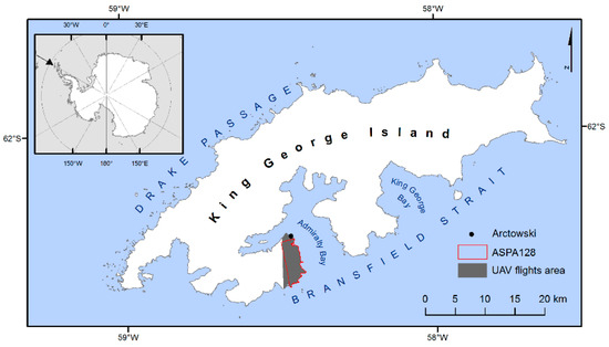
Figure 1.
Location of King George Island, Antarctic Specially Protected Area No. 128 and the unmanned aerial vehicle flights.
Only about 10% of KGI’s surface (138 km2) is ice-free, and the ice cover consists of three main ice domes and seventy glacier drainage basins [6]. The highest elevation reaches slightly more than 700 m a.s.l. at a dominating central dome. The glaciers flow radially out of the domes and terminate at the sea coast or slightly inland. As reported by Simões et al. [6], retreat of the glacier fronts between 1956 and 1995 caused a reduction of 7% (89 km2) of the total ice-covered area. A more recent study of Rückamp et al. [7] shows that between 2000 and 2008 the loss of glacierized surface amounted to about 20 km2 (about 1.6% of the island area). The area of glaciers flowing east from Warszawa Icefield (southern ice dome of KGI) to Admiralty Bay, the main inlet from the SE, shrank by 31.3% in years 1979–2018 [8].
Changes in the glacial system affect the nearby land ecosystems in many ways. Recently deglaciated landscapes undergo rapid geomorphic as well as biologic changes [5,9,10]. High sediment loads originating from paraglacial erosion of recently exposed landforms are quickly delivered to the coastal zone [9,11,12,13].
Antarctic Specially Protected Area No. 128 (ASPA 128), located on the west coast of Admiralty Bay in the vicinity of the Henryk Arctowski Polish Antarctic Station (Arctowski), hosted extensive geomorphological research in years 1990–1992 during the Polish expeditions to KGI [14,15,16]. Since that time, the glaciers underwent significant recession [8]. In recent years, due to developments in remote sensing, mainly unmanned aerial vehicle (UAV) technology and terrestrial laser scanning, several geomorphological studies were performed in this area. They focused on periglacial landforms on Demay Point peninsula [17], glacial dynamics and foreland development of Ecology Glacier [18] and Baranowski Glacier [13], and volcanic landforms on Penguin Island [19]. Recession of all of the glaciers in the area since 1979 was well documented by Pudełko et al. [8], but an overall geomorphological study of contemporary glacial forelands in ASPA 128 has been lacking.
The aim of this study is to fill this gap by determining the area and spatial distribution of glacial landforms sensu lato developed on main glacial forelands in the area, namely Ecology Glacier foreland (EGF), Sphinx Glacier foreland (SGF) and Baranowski Glacier foreland (BGF) (Figure 2). We used aerial photographic images taken by a fixed-wing unmanned aerial vehicle (UAV) during the Beyond Visual Line of Sight (BVLOS) flights, followed by Geographic Information System data processing to detect and quantify the landform assemblages.
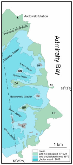
Figure 2.
Location of main glaciers and topographic features on the west coast of Admiralty Bay (Antarctic Specially Protected Area No. 128) and Arctowski; contours of glaciers from Pudełko et al. [8]. SH—Sphinx Hill, CN—Czajkowski Needle, ZA—Zamek, AP—Agat Point, SI—Siodło, BR—Brama, DE—Demay Point, BA—Bastion.
The BVLOS fixed-wing UAV operations allow us to cover a significantly larger surface and gather high-resolution images (with a higher resolution for KGI area than available with commercial satellite images) in one flight in comparison with the Visual Line of Sight operations that usually utilise rotary-wing UAVs. In remote, difficult-to-access polar locations, BVLOS UAV operations allow for multifaceted environmental analyses far away from a polar station, saving time and logistic efforts [19,20]. Recent developments in polar UAV operations, including Antarctic missions, are described in Zmarz et al. [19] and Bhardwaj et al. [21].
1.2. Characteristics of the Study Area
The study area was located in ASPA 128, western coast of Admiralty Bay, King George Island, South Shetland Islands, West Antarctica (Figure 1 and Figure 2). It is a big lowland ice-free area (about 16.8 km2), covered by diverse tundra communities [22], constituting a favorable place for huge breeding colonies of marine birds and pinnipeds [23].
Bedrock is generally composed of basaltic and andesitic lavas, interstratified sediments of Eocene–Oligocene age and some Pleistocene plugs and dikes [24]. Northern latero-frontal moraines of Ecology Glacier (Figure 2) are deposited against basalts and andesites alternating with breccias and tuffs (Arctowski Cove Fm.). Between Ecology Glacier and Sphinx Glacier the bedrock is composed of tholeiitic and subordinately andesitic lavas with pyroclastic intercalations (Llano Point Fm.). Southern latero-frontal moraines of Baranowski Glacier are deposited against porphyritic lavas, tuff-breccias, siliceous pisolites, conglomerates and lapilli tuffs (Demay Point Fm.) [24]. Bedrock is overlain predominantly by glacial ice and sediments deposited by the glaciers and meltwaters, weathering and slope sediments and marine sediments, which compose raised terraces, a contemporary beach and a storm ridge [15,25].
The climate of the study area is polar maritime [26] with some participation of continental air from the south [27] resulting in highly dynamic weather conditions. The mean annual air temperature (MAAT) calculated for joined periods 1977–1999, 2006–2007 and 2012 is −1.5 °C [28]. An increase in MAAT by 1.2 °C occurred for the period of 1948–2011 on KGI [29], which resulted in retreat of local glaciers [16,30,31]. However, a set of end moraines developed at the contemporary margin of Baranowski Glacier and recent deceleration of glacial surface lowering [18] can be attributed to a slightly negative temperature trend observed since the beginning of the twenty-first century [32]. Thermal conditions result in the permafrost table depressing well below 1.0 m or even absent at altitudes close to sea level and glacier forelands [33,34]. This allows for free circulation of glacial melt water. Glacial lagoons receive water from glaciers, tides and relatively abundant precipitation. Tide amplitude is usually about 1.5 m [35], which results in a well-developed beach and a storm ridge.
According to Marsz and Styszyńska [27], the mean annual precipitation for the period 1978–1996 was 505.7 mm and mean annual number of rainy days was 205. The snow cover is highly variable, and sometimes snow cover can melt almost completely, even in winter [36], but may also appear after summer snow storms. Average annual wind speed equals 6.6 ms−1 [32] with frequent wind gusts sometimes exceeding 65.0 ms−1 [11,37]. Storms are typical climate elements in the region, which makes the use of UAV difficult and risky.
Ecology Glacier, Sphinx Glacier and Baranowski Glacier flow east from Warszawa Icefield, the plateau of which lies between 400 and 460 m a.s.l. Their equilibrium line altitude in the 21st century varied between 156 m a.s.l. in 2012/2013 [38] and 290 m a.s.l. in 2006/2007 [8]. Since the first availability of aerial images, taken in 1978/1979 [39,40,41], the glaciers snouts retreated by a distance from 260 m (Baranowski Glacier) to 740 m (Ecology Glacier). Glacier forelands in places inundated by lagoons constitute a significant part of ASPA 128. Retreat rates of the glaciers slowed down, following recent climatic cooling [18,32].
2. Materials and Methods
2.1. Data Acquisition
The Beyond Visual Line of Sight (BVLOS) flights were performed using the PW-ZOOM fixed-wing UAV [19,42] designed, manufactured and tested at the Warsaw University of Technology in Poland. The airplane was equipped with an automatic control system (autopilot) linked with a telemetry module. A similar module was used in the Ground Control Station, which was connected to a computer running special software HORIZONmp (MicroPilot, Stony Mountain, Canada) for planning the flight path and managing the UAV flight. The flight was therefore autonomous, although at any time it could be interrupted by sending the order to return to the base. The operation was performed on 15–17 November 2016 by a three-person team: the remote control pilot, the ground control station operator and the technical operator (all had BVLOS licenses issued by national authorities).
The photogrammetry grid was designed over the west coast of Admiralty Bay and the forelands of retreating glaciers (Figure 2 and Figure 3) with starting and landing points near Arctowski. The distance between the grid lines was ~ 73 m, which provided 70% forward and side overlap, the length of the lines was 7500–10,000 m and flight altitude was 500 m a.s.l. The images were gathered in three flights 7 h in total, covering a distance of 720 km (Table 1).
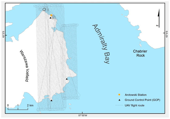
Figure 3.
Unmanned aerial vehicle flight routes during the Beyond Visual Line of Sight operation over the west coast of Admiralty Bay.

Table 1.
The parameters of the aerial survey to the Antarctic Specially Protected Area No. 128 performed on 15–17 Nov. 2016.
Using UAVs to collect environmental data is a quite new phenomenon in Antarctica; therefore, guidelines for safe UAV use are currently being developed (e.g., COMNAP RPAS Handbook of the Council of Managers of National Antarctic Programs; COMNAP). The authors of this paper had to meet certain obligations, such as preparing an Environmental Impact Assessment, obtaining permits for taking or harmful interference of Antarctic fauna and flora and providing information needed for information exchange between parties to the Antarctic Treaty. All parties conducting operations on KGI, as well as the International Association of Antarctica Tour Operators (IAATOs), were informed about our UAV operation. A chain of communication was pre-agreed with Base Frei (Chile), which controls flight operations on KGI.
2.2. Data Processing
The images were obtained in RAW format during the flight and converted to JPEG format in Digital Photo Professional version 3.13.0.1 (Canon INC) software. All images had georeferences (X, Y, Z) registered by the autopilot logger mounted on the UAV. For geolocation of images, the GPS Receiver GP-E2 with 1575.42 MHz frequency was used, which allowed for horizontal accuracy < 5m. To estimate vertical accuracy, a reference measurement taken near the Arctowski station was used (a concrete pillar named Jasnorzewski Point). The data were obtained by continuous GPS measurements and other two ground control points (GCPs), marked in Figure 3. The value of deviations measured at GCP was 2 m. Automatically classified dense point clouds were built by Metashape based on the estimated camera positions.
Images showing ASPA128 were processed into an orthophoto with a resolution of 0.06 m and a Digital Elevation Model (DEM) of 0.25 m resolution in the original WGS84 coordinate system. The Agisoft Metashape Professional software Version 1.3.2 build 4205, 64 bit (Agisoft LLC) and Structure from Motion (SfM) algorithm were used to create the orthophoto and DEM. The orthophoto was converted to the Universal Transverse Mercator system, zone 21S (EPSG:32721) in ESRI (Environmental Systems Research Institute) ArcGIS 10.3 software.
Based on the orthophoto and DEM, the landforms were manually determined by vectorization in ESRI ArcGIS 10.3 software at varying scales. Patches of relatively uniform landforms or bodies of water (e.g., outwash, ground moraine, glacial lagoon, and patches of repetitive landforms, e.g., recessional end moraine ridge complex) were vectorized in a relatively small scale (1:1000) but, in places, individual objects such as a snow patch, an esker or a drumlin required more detailed mapping at a scale of 1:500. During our UAV missions the snow patches were relatively abundant, which inhibited geomorphological interpretation of UAV images. Due to this we did not map the southernmost foreland of Tower Glacier and Windy Glacier (Figure 2).
Our geomorphological mapping was not based on DEM segmentation, but solely on image classification based on our geomorphological experience acquired in different glacial forelands and studies of relevant literature (see Discussion). Main characteristics of landforms (area, shape, association with other landforms) and justification of their determination are presented in Results.
3. Results
3.1. General Characteristics and Quantification of Landforms
The general geomorphological mapping included the following units: glacial depositional landforms, fluvial and fluvioglacial landforms, littoral and lacustrine landforms, bodies of water (lakes, lagoons and rivers), glacier ice (marginal parts of glacier) and snow patches, bedrock and other surfaces not recognized or not associated with glaciers (Figure 4). Bedrock includes both glacially eroded landforms and coastal rocky outcrops because we were unable to distinguish between surfaces of glacial abrasion, quarrying or coastal abrasion. Rock surfaces of residual hills and taluses, and not recognized landforms outside of glacial forelands, were named “bedrock” or “other”, respectively.
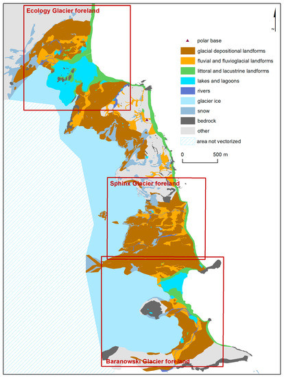
Figure 4.
West coast of Admiralty Bay on King George Island and geomorphological setting of Ecology Glacier, Sphinx Glacier and Baranowski Glacier forelands; note a small seasonal US polar base between Ecology Glacier and Sphinx Glacier; map based on images obtained by the unmanned aerial vehicle [43].
It is frequently difficult to determine the lateral boundary of glacier forelands, especially in case of adjacent glacier tongues or lobes (e.g., the southern limit of EGF). Therefore, we decided to limit our analysis to rectangular frames (Figure 4). The frames for SGF and BGF are slightly overlapping in order to show immediate surroundings of both forelands, but we calculated the statistics provided below (Figure 5) taking into account the crest of a medial moraine ridge. Glacial depositional landforms cover most of the forelands’ area: 472,867 m2 on EGF where they constitute 45.3% of mapped landforms (excluding snow patches and “other surfaces”), 524,459 m2 (73.2%) on SGF and 508,749 m2 (53.9%) on BGF (Figure 5).
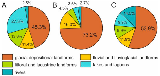
Figure 5.
Share of groups of landforms in mapped area of forelands of (A) Ecology Glacier, (B) Sphinx Glacier and (C) Baranowski Glacier.
3.2. Landform Characteristics
Below we present characteristic features of landforms mapped in detail on forelands of Ecology Glacier, Sphinx Glacier and Baranowski Glacier (Figure 6) with a short interpretation.
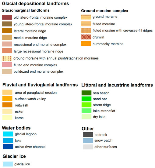
Figure 6.
Legend to detailed geomorphological maps in Figure 7, Figures 9 and 10.
3.2.1. Glacial Depositional Landforms
Glaciomarginal Landforms
This group includes old and young latero-frontal moraine complexes, lateral and medial moraine ridges, recessional end moraine ridge complex, large recessional moraine ridges, ground moraine with annual push/stagnation moraines, fluted end moraine complex and bulldozed end moraine complex.
The old latero-frontal moraine complex marks the outer margin of glacier forelands, possesses a curved shape and is best developed in EGF, where it creates a continuous belt over a distance of about 1000 m (Figure 7). The moraines are up to 12 m high with depressions overgrown by shallow tundra (Figure 7A and Figure 8A) and host small lakes. The young latero-frontal moraines are much higher (up to 40–50 m) and are ice-cored according to Rachlewicz [16] and Kostrzewski et al. [14,15]. On aerial images they can be easily distinguished from the older moraine complex by much sparser vegetation (Figure 7 and Figure 8A).
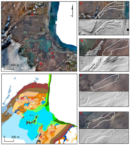
Figure 7.
Ecology Glacier foreland: an orthophoto and a detailed geomorphological map (see Figure 6 for legend), and examples of vectorized landform units (white polygons) based on the orthophoto and the Digital Elevation Model; A—old (more distal from the glacier) and young (more proximal) latero-frontal moraine complex; B—fluted moraine, C—fluted moraine with crevasse-fill ridges, D—ground moraine with annual push/stagnation moraines; E1 and E2 mark drumlins, which are discussed in Section 4.3, Figure 11, Table 2.
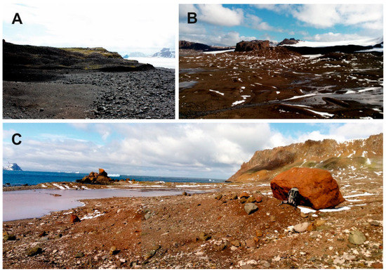
Figure 8.
Photographic documentation of selected landforms (phot. G. Rachlewicz, 2016): A—an outwash and the young latero-frontal moraine complex deposited in the northern part of Ecology Glacier foreland; the older latero-frontal moraine complex (overgrown with mosses) is seen in the background; moraines are undercut by coastal erosion; B—large recessional end moraine ridges and an outwash deposited within the ground moraine complex on the Sphinx Glacier foreland are visible on the foreground; the shaded long ridge in the background is Błaszyk Moraine (medial moraine), and the table mountain is a former nunatak Siodło in the Baranowski Glacier foreland; C—a fluted moraine of the Baranowski Glacier foreland and a transfluent lake enclosed by a storm ridge, collecting waters from two glacial rivers; high slopes of Demay Point are seen in the background.
Lateral moraines are relatively short and straight running ridges, disconnected from the latero-frontal moraine complex. We mapped them only in the northern part of SGF and the southern part of BGF (Figure 9 and Figure 10).
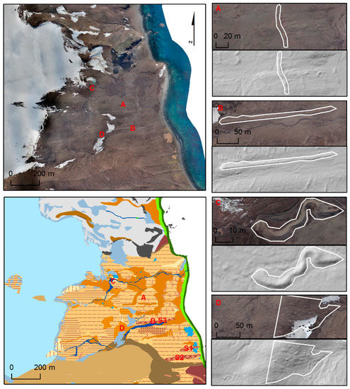
Figure 9.
Sphinx Glacier foreland: an orthophoto and a detailed geomorphological map (see Figure 6 for legend), and examples of vectorized landform units (white polygons) based on the orthophoto and the Digital Elevation Model; A—large recessional moraine ridge; B—drumlin, C—esker, D—hummocky moraine; S1–S3 mark drumlins, which are discussed in Section 4.3, Figure 11, Table 2.
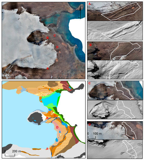
Figure 10.
Baranowski Glacier foreland: an orthophoto and a detailed geomorphological map (see Figure 6 for legend), and examples of vectorized landform units (white polygons) based on the orthophoto and the Digital Elevation Model; A—contemporary end moraine complex; B—ground moraine, C—outwash, D—fluted end moraine complex.
A medial moraine ridge developed between Sphinx Glacier and Baranowski Glacier has been named Błaszyk Moraine [40,44]. It is very long (1150 m), wide (up to 250 m) and over 100 m high at its western part, towards its origin at Zamek hill (Figure 2, Figure 8B, Figure 9 and Figure 10). It has been already well visible in aerial images from 1978/1979 [40], which testifies to its relatively old age.
Recessional end moraine ridge complexes are arch-shaped patches of moraine ridges parallel to the glacial front, relatively long and frequently spaced. They are developed in the northern part of EGF, between 250 and 580 m away from the contemporary glacial front (Figure 7).
Large recessional moraine ridges are individual landforms, between 15 and 65 m long and 3 to 8 m wide, best developed in the distal part of SGF (Figure 9 and Figure 9A). Sometimes a distinctive pattern of clear-cut small ridges running parallel to the glacier margin is seen on the ground moraine and interpreted as annual push/stagnation moraines. The small ridges are best developed immediately south of the glacial lagoon on EGF (Figure 7 and Figure 7D), close to the Sphinx Glacier front (Figure 9) and north of the lagoon on BGF (Figure 10). The ridges are usually between 10–30 m long, 1.0–2.5 m wide and spaced 5 to 10 m from each other.
The fluted end moraine complex is developed only in the central and southern parts of the BGF within the first 100 m distance for the contemporary glacial front, but separated from the glacier by a narrow 20 to 40 m wide belt of the bulldozed end moraine complex (Figure 10). The fluted end moraines are spaced between 5 to 15 m and are about 5 m wide (Figure 10D). The flutings allow to infer that the moraine complex was deposited due to submarginal freeze-on and emplacement of fluted sediment slabs [45].
The bulldozed end moraine complex consists of narrow parallel ridges adjacent to the glacier margin with no flutings (Figure 10A). Lack of fluting allows to infer that the dominant process of deposition was bulldozing of proglacial sediments. Both complexes of end moraines (fluted and bulldozed) do not exhibit sawtooth planform geometries, which are typical for tensile-fractured glacial snouts [45,46,47].
Ground Moraine Complex
This group of landforms includes ground moraine, fluted moraine, fluted moraine with crevasse-fill ridges and drumlins.
The ground moraine was mapped in places of relatively smooth surface (Figure 10B). In places (e.g., eastern part of SGF) one can notice small-scale ridges, which can be interpreted as remnants of annual push/stagnation moraines or crevasse-fill landforms. However, they are not clearly seen on orthophoto and DEM; therefore, we applied the general term of ground moraine in such cases.
The fluted moraine possesses a characteristic pattern of streamlined ridges (flutes) and grooves and occurs commonly in interior parts of glacial forelands, which is a common situation in other glacial land systems [48,49,50]. Some flutings are developed on a lee side of an anchored boulder, and some are segmented. In the southern parts of EGF and SGF the flutings are sometimes overlain with diagonal (ice-flow oblique) pattern of small ridges, 5 to 50 m long and 1.2 to 5 m wide (Figure 7C), which are interpreted as crevasse-fill ridges.
Based on analyses of length, width and elongation ratios of 165 vectorized, streamlined, longitudinal landforms developed in studied forelands, we distinguished two drumlins on EGF (E1 and E2) and three on SGF (S1–S3) (Figure 7 and Figure 9). For further information about morphometric characteristics of flutes and drumlins see Discussion (Section 4.3, Figure 11, Table 2).
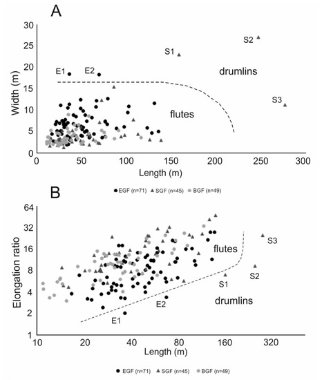
Figure 11.
Length-to-width (A) and length-to-elongation ratio (B) diagrams for 165 analyzed flutings and drumlins (note that the axis scales of the diagram B are logarithmic); drumlins are marked E1 and E2 (Ecology Glacier foreland) and S1-S3 (Sphinx Glacier foreland).
Table 2.
Lengths and elongations of drumlins on the Ecology Glacier foreland and the Sphinx Glacier foreland juxtaposed with maximum elongation according to Clark et al. [82].
3.2.2. Fluvial and Fluvioglacial Landforms
Fluvial and fluvioglacial landforms are erosional and characterized by areas of paraglacial erosion, surface wash valley and deposition of outwash, eskers and kames (Figure 9). Altogether, they represent 11.4% (EGF), 15.5% (SGF) and 11.6% (BGF) of the mapped surface.
In some places, especially in the northern part of EGF (Figure 7), a dense network of erosional gullies developed on morainic slopes and were mapped as areas of paraglacial erosion. The gullies are up to 100 m long, and the largest vectorized polygon (on EGF) occupies 19,147 m2. They constitute an important source for outwash material and testify to significant paraglacial reworking of glacial sediments [9]. Surface wash valleys are shallow bowl-shaped valleys developed between glacial forelands (Figure 4, Figure 7 and Figure 9) and mapped by us in order to allow for better spatial orientation. They originate from fluvial erosion of snow melt and rain waters.
The largest fluvioglacial landforms are outwashes, which cover a similar area in each of the forelands: 89,739 m2 on EGF, 101,541 m2 on SGF and 95,768 m2 on BGF. Stripes of outwash can usually be found in depressions within ground moraine, parallel to the glacier margins (Figure 7, Figure 9 and Figure 10). Eskers are poorly developed and create simple sinusoidal ridges, up to 65 m long and 5 m wide (Figure 9C). There are only two very small patches interpreted after Sziło and Bialik [13] as kames on BGF, between storm ridge and outwash (Figure 10).
3.2.3. Littoral and Lacustrine Landforms
Sea beach constitutes an almost continuous strip of land (Figure 4), between 10 and 60 m wide, adjacent to the sea, interrupted in places by rocky outcrops (e.g., on BGF; Figure 10). Sand bars developed on EGF and BGF, protecting sea water from easy access to glacial lagoons in a dynamic coastal environment (Figure 7 and Figure 10) [35]. Directly behind the beach there is a clearly visible strip of land that we interpret to be a storm ridge due to its dryer surface in comparison with the beach (Figure 7, Figure 9 and Figure 10). On EGF and BGF, coastal landforms smoothly evolve into lacustrine strandflats developed around shorelines of glacial lagoons (Figure 7 and Figure 10).
3.2.4. Bodies of Water
The largest body of water is by far the glacial lagoon on EGF (251,257 m2), which demarcates a 621 m long tidewater ice cliff of Ecology Glacier (Figure 7). There is also a smaller lagoon (62,736 m2) at Baranowski Glacier (Figure 10), resulting in a much smaller (46 m long) direct contact between water and the glacial front.
Lakes occupy comparable areas in the studied forelands, between 10,517 m2 (SGF) and 16,159 m2 (BGF) (Figure 7, Figure 9 and Figure 10). Most of the lakes are bodies of relatively stagnant water, except for one transfluent lake in BGF located at the confluence of two glacial rivers (Figure 8C and Figure 10).
We mapped active river channels only where river water could be seen. The width of the marked channel depicts the river bed (contemporary filled with water) together with adjacent bars, which were dark on the images due to high water content (Figure 7, Figure 9 and Figure 10). In the southern part of SGF the active river channel disappears downstream, which allows us to infer that river water percolates down into alluvial sediments marked as outwash (Figure 9).
3.2.5. Snow Patches, Bedrock and other Surfaces
There were numerous snow patches varying greatly in size during austral summer of 2016 when the UAV images were obtained. Snow caused major problems in mapping of SGF because the glacier area did not differ from proglacial snow patches in terms of color and texture (Figure 9). Bedrock is far more present on BGF due to the outcrops at the former nunatak Siodło, two peninsulas (Agat Point and Block Point) as well as the northern escarpment of Demay Point along the southern margin of BGF (Figure 8C and Figure 10).
4. Discussion
4.1. BVLOS Data Acquisition and Interpretation
Studies in the Antarctic environment are frequently performed in remote ice-free areas (oases) or islands, which are not easily accessible [51]; therefore, systematic terrestrial surveys are usually limited to small areas located in the vicinity of research stations [52,53]. This can be overcome by the use of the BVLOS fixed-wing UAV flights [17,19].
However, BVLOS flights are still seldom used in geomorphological studies, despite the development of autonomous controllable micro-airplanes technology and platforms designed to work effectively in harsh Antarctic environments [54,55]. For example, our PW-ZOOM plane tolerates strong, unpredictable Antarctic winds up to 23 ms−1 [42] and still performs high-quality photogrammetric flights [17,19,43]. The BVOLS fixed-wing UAV operations allow to cover a significantly larger surface in comparison with rotary-wing UAVs, which are frequently used in a variety of geomorphological studies [45,49,56,57,58,59,60,61,62,63].
In remote areas of the Antarctic environment, where the placement of the ground control points (GCPs) is impossible or requires a lot of time and logistics, the BLVOS operations offer a good solution (in our case, we used GCP, which was located near the Arctowski station, Jasnorzewski Point). The horizontal accuracy of the objects seen on images obtained in our study is limited by the accuracy of the GPS receiver mounted on the UAV (<5 m). This can be a problem in repetitive high-precision mapping (e.g., in monitoring erosion [57,58]), but it is sufficient in determining landform assemblages and calculating their area, aspect or other parameters [17,19].
4.2. Glacial Dynamics
The studied glacier forelands differ between themselves most importantly in the length of ice cliffs and the size of glacial lagoons, which significantly influences calving rate and frontal recession. Ice thickness of the frontal parts of Ecology Glacier, Sphinx Glacier and Baranowski Glacier does not exceed 100 m, and ice flow velocities are below 100 m yr−1 [64], which leads to their classification as normal glaciers (not fast glaciers) [12,65,66]. However, the landform assemblages observed could be inherited from discontinuous fast ice flow of tidewater glaciers [67], which probably occurred when ice was thicker, had more direct contact with seawater and calving rate was higher. Such glaciers developed bed-flow type landform assemblages with push moraines in land-based parts (N segment of EGF), flutes and drumlins on the ground moraine behind glaciers margins, which either developed terrestrially (EGF) or in the sea (SGF, BGF). A deformable bed is present on the west coast of Admiralty Bay, constituted by soft sediments [16,68] and probably high pore water pressure due to low elevation above sea level and shallow bedrock inhibiting downward percolation of meltwaters. This would decrease the shear strength of subglacial sediments and facilitate fast ice flow and deformation of subglacial sediments [12,69,70,71].
The thermal structure of the studied glaciers is yet unknown, and most probably underwent change since the onset of climate warming in the 20th century. Polythermal and temperate glaciers are present on KGI [72,73], although no indirect evidence of temperate (or polythermal) state of ice was observed, such as winter sub- or englacial water discharge or icings [11,27]. Poor development of eskers (short curved ridges, not segmented) allows only limited interpretation of the routing of glacial melt water within the glaciers, probably in subglacial tunnels [12]. The thermal structure (probably polythermal) and significant amount of coarse-grained sediments, like marine gravel found in glacial sediments of EGF, SGF and BGF [16], did not inhibit fast ice flow and formation of flutings and drumlins [48], especially when the glaciers extended to the coastline where calving facilitated fast flow of glacial ice. Changes in ice flow velocity most probably resulted from calving events, which temporarily distorted the pressure equilibrium between an ice-cliff and seawater, and triggered faster ice flow [74]. Following ice mass loss, glaciers thinned and largely retreated on land. The flutes testify for unsteady basal slip velocity and basal water pressure [50].
There are no well-documented events of glacial surges of the studied glaciers. However, according to Birkenmajer [24] between 1950 and 1977 Ecology Glacier and Baranowski Glacier probably surged over coastal storm ridges and beaches forming push moraines, which we named young latero-frontal moraine complexes. Extensive flutings and crevasse-fill ridges could be inherited form surge events [75,76].
Significant retreat of the glaciers since 1979 created landform assemblages, which testify for frontal recession with glaciers maintaining their integrity and not turning into blocks of dead ice. Ground moraine complex is not covered by landforms associated with aerial disintegration of glacier such as kames, kame terraces and kettle-holes [12].
4.3. Flutings or Drumlins?
The shape and origin of subglacial streamlined ridges (flutes and drumlins) has received considerable attention in geomorphological research conducted almost exclusively in the northern hemisphere [12,49,77,78,79,80,81,82]. Landforms, determined by us as drumlins, create distinctive two groups separated from flutings on the length-to-width diagram (Figure 11A). Either their width is significantly greater (E1, E2 and S1–S2) or length (S1–S3). On the length-to-elongation ratio diagram (Figure 11B) the boundary between the flutings and the drumlins is shown by the dashed line, which cuts-off the landforms of lowest elongation ratio, except for landform S3.
Our designation of drumlins is in accordance with findings of Clark et al. [82] who discovered that the maximum elongation ratio of drumlins scales with their length (Figure 11B, Table 2). However, only drumlins in EGF (E1 and E2) fit to the equation determined by Clark et al. [82]:
where Emax is the maximum elongation and L is length. Very long (>100 m) longitudinal landforms on SGF (S1–S3) could be called megaflutes instead of drumlins [80]. However, we decided to name them drumlins due to their outstanding length and significant width in comparison with flutings (Figure 11A,B) and to avoid extra entities in the already complex map legend (Figure 6).
Emax = L1/3
Contrary to the most widely accepted cavity-infill model [12,77,79] in EGF, SGF and BGF, only some flutes start at the lee side of boulders, suggesting basal ice crevassing [78] or melt-out of longitudinal thickenings of basal debris-rich ice [81].
4.4. Ecology Glacier Foreland
The most profound features of EGF are the large old and young latero-frontal moraine ridges, which can be traced along the margin of the foreland, and the large glacial lagoon. The old latero-frontal moraines were deposited during the Little Ice Age (LIA) glacial maximum, which ended in this region around AD 1850 [31,83]. The young latero-frontal moraine complex has developed in the 20th century, before 1979 when the rapid deglaciation started [31]. However, in 1989 they were still very close to the glacier front, and the ice cliff was still at the open waters of Admiralty Bay [8]. The more frontal parts of both morainic complexes are of push origin, which can be inferred from their structure, beach material and whaling artefacts from the first decades of 20th century and artefacts from the 1950s embedded within glacial till [16,24].
The lagoon plays a significant role in shaping the pattern of glacial retreat. The glacial cliff retreats fastest, producing two characteristic concavities: one in the northern side, another in the southern part of the glacial cliff. According to Pętlicki et al. [18], the glacial lagoon depth in these places is 5–8 m, while in the central part of the glacial cliff where glacial retreat is slower, the depth of the lagoon is less than 2 m. It is probable that the sand bar closing the lagoon is deposited on a subaqual moraine built at the former grounding line [84].
Highly negative mass balance over 1979–2016 resulted in ice elevation change rate in the ablation area between ‒1.7± 0.4 m yr−1 in 1979–2001 to ‒0.5 ± 0.6 m yr−1 in 2012–2016 [8]. The front recession between 1978 and 2016 was about 650 m, which translates to about 17 m yr−1. Three belts of recessional end moraine ridge complex in the northern part of EGF (Figure 7) were deposited between 1989 and 2001, and surface of islands visible in the central part of the lagoon underwent deglaciation in the beginning of the 21st century [8,18]. The recent deceleration of retreat [18] has probably resulted in the formation of annual push/stagnation moraines in the northern part of the glacier margin (Figure 7).
4.5. Sphinx Glacier Foreland
The surface area of Sphinx Glacier is probably smaller than on our geomorphological map (Figure 9), due to abundant snow cover present on the glacier and along its margin during data acquisition. On the orthophoto of Pudełko [40] two separate lobes (northern and southern) divided by the Czajkowski Needle nunatak are visible (Figure 2). A later publication [8] shows satellite images taken on 13 February and 10 March 2018, in which the glacier is clearly divided into the northern and southern, more fractured lobe (Figure 2). Our images display some dark surface between the two lobes, which we interpreted as medial moraine, bedrock outcrops or fluted moraine.
The most characteristic geomorphic features of SGF are large areas of ground moraine. Fluted moraine characterizes more proximal parts of the foreland (deposited after 2011), and numerous large recessional moraine ridges in a more distal parts (last two decades of the 20th century) together with relatively well-developed drumlins [8].
There is a characteristic pattern of outwash, which is predominantly deposited in shallow valleys within the ground moraine running perpendicular to the front of the northern lobe.
Sphinx Glacier reached open sea during the LIA maximum along its whole frontal margin, as there is no evidence it was enclosed by in land-based latero-frontal moraines. An ice-cliff must have resulted in calving, which in turn facilitated relatively vast ice flow. Between 1979 and 2016 the glacier receded by about 380 m in its southern part and only about 190 m in its northern part. This means an average recession rate between 5 and 10 m yr−1, which is much slower than that of Ecology Glacier and can be explained by the absence of a glacial lagoon.
4.6. Baranowski Glacier Foreland
The Baranowski Glacier foreland is clearly divided into the northern and the southern lobes divided by a former nunatak called Siodło (Figure 2). The northern lobe receded between 1979 and 2016 by about 620 m, indicating a mean annual rate of recession 17 m yr−1. The southern part of the southern lobe receded only by about 240 m (6.5 m yr−1). This asymmetry is caused by the influence of calving along the ice cliff of the northern lobe. Furthermore, along the margin of the southern lobe there is a very well-developed complex of contemporary end moraines, probably linked with the recent climatic cooling.
The ground moraine complex is visible in front of the two lobes and possess a typical structure with fluted moraine in the more proximal part of the foreland and ground moraine (not fluted) in the more distal part [48,49,50]. A belt of outwash developed in an arch pattern separates the fluted moraine from the ground moraine.
The end moraine complex probably resulted from the recent (since 1998/1999) climatic cooling [32] and slowing of glacier retreat. The change of the character of end moraines at the southern part of the glacier from fluted to bulldozed allows to infer that there was a change in a mode of deposition from subglacial freeze-on and stacking of sediment slabs to bulldozing of soft sediments [12,45,85]. However, due to the complexity of these processes, the analysis based solely on images obtained preclude further inference.
5. Conclusions
Image acquisition by fixed-wing UAV PW-ZOOM proved to be a robust technique in harsh polar conditions of marine Antarctica. The images obtained allowed to save time required for a popular approach of using rotary UAV platforms. We argue that photogrammetric UAV BVLOS flights provided high-quality data, much better than satellite imaging, and should be regarded as a suitable tool in gathering geomorphological data in remote polar locations. The high-resolution orthophoto with DEM allowed for detailed vectorization of landforms in glacial forelands.
As all mappings based on remote sensing, our mapping also suffers from some uncertainties. These result from snow patches and too low image resolution to distinguish certain landforms (e.g., glacially abraded rock surfaces typical of whalebacks or roche moutonnée could not be detected). The glaciers receded substantially since the last extensive geomorphological studies, exposing vast new foreland area; therefore, more in-field work would be necessary to support our photointerpretation. Geomorphological fieldwork would be necessary to verify our interpretation in certain places (e.g., crevasse-fill origin of some ridges). The issue of kames would also require verification, as we could map them only on one foreland based on a former study because no clear and determining feature was visible on our images. It would be especially interesting to check the internal structure of fluted and bulldozed end moraines developed on BGF as these landforms may testify for most contemporary glacial dynamics.
The studied glacial forelands host landform assemblages typical of discontinuous fast ice flow of tidewater glaciers over deformable beds, which results in large latero-frontal push moraine complex, flutes and drumlins. Ice flow velocity decreased as a result of recession from coastline (most rapid after 1979), resulting in significant decrease in the length of ice cliffs and glacier cover thinning. Glacial lagoons are responsible for asymmetric recession of Ecology Glacier and Baranowski Glacier fronts. Frontal recession for the last forty years revealed ground moraine complex marked with flutings, drumlins, annual push/stagnation moraines and crevasse-fill ridges. The fluted and bulldozed end moraine complexes developed near the front of the southern lobe of Baranowski Glacier are attributed to recent climatic cooling.
Author Contributions
Identification, vectorization, classification and interpretation of landforms on UAV images, writing and editing of the manuscript, M.D.; programming and coordinating UAV BVLOS flights, GCS BVLOS operator, image acquisition and elaboration of orthophoto and DEM, writing of the manuscript, A.Z.; designed, manufacturing and airworthiness maintaining of the PW-ZOOM UAV, M.R.; consultation and elaboration of Introduction, M.K.-A., K.C.; elaboration of maps in GIS, I.K.; vectorization of landforms, K.L.; consultation in interpretation of maps G.R. All co-authors provided valuable comments to the manuscript. All authors have read and agreed to the published version of the manuscript.
Funding
The research leading to these results has received funding from (1) the Polish-Norwegian Research Programme operated by the National Centre for Research and Development under the Norwegian Financial Mechanism 2009–2014 in the frame of Project Contract No 197810; (2) project innoVation in geOspatiaL and 3D daTA (VOLTA) financed by the European Union’s Horizon 2020 research and innovation programme under grant agreement No 734687, further co-funded from Polish resources for science in the period 2017–2020 awarded for the implementation of an international co-financed project; (3) grant NCN OPUS 2013/11/B/ST10/00283 (supporting fieldwork of Grzegorz Rachlewicz).
Acknowledgments
The data used in the paper were collected with the support of Henryk Arctowski, Polish Antarctic Station. We would like to thank Joseph C. Abshire for proofreading of the manuscript. The large-scale maps will be available to the readers on request.
Conflicts of Interest
The authors declare no conflicts of interest. The funders had no role in the design of the study; in the collection, analyses, or interpretation of data; in the writing of the manuscript, or in the decision to publish the results.
References
- Meredith, M.P.; King, J.C. Rapid climate change in the ocean to the west of the Antarctic Peninsula during the second half of the 20th century. Geophys. Res. Lett. 2005, 32, 19604. [Google Scholar] [CrossRef]
- Turner, J.; Barrand, N.E.; Bracegirdle, T.J.; Convey, P.; Hodgson, D.A.; Jarvis, M.; Jenkins, A.; Marshall, G.; Meredith, M.P.; Roscoe, H.; et al. Antarctic climate change and the environment: An update. Polar Rec. 2014, 50, 237–259. [Google Scholar] [CrossRef]
- Cook, A.J.; Fox, A.J.; Vaughan, D.G.; Ferrigno, J.G. Retreating Glacier Fronts on the Antarctic Peninsula over the Past Half-Century. Science 2005, 308, 541–544. [Google Scholar] [CrossRef]
- Turner, J.; Lachlan-Cope, T.; Colwell, S.; Marshall, G.J. A positive trend in western Antarctic Peninsula precipitation over the last 50 years reflecting regional and Antarctic-wide atmospheric circulation changes. Ann. Glaciol. 2005, 41, 85–91. [Google Scholar] [CrossRef]
- Znój, A.; Chwedorzewska, K.J.; Androsiuk, P.; Cuba-Diaz, M.; Giełwanowska, I.; Koc, J.; Korczak-Abshire, M.; Grzesiak, J.; Zmarz, A. Rapid environmental changes in the Western Antarctic Peninsula region due to climate change and human activity. Appl. Ecol. Environ. Res. 2017, 15, 525–539. [Google Scholar] [CrossRef]
- Simões, J.C.; Bremer, U.F.; Aquino, F.E.; Ferron, F.A. Morphology and variations of glacial drainage basins in the King George Island ice field, Antarctica. Ann. Glaciol. 1999, 29, 220–224. [Google Scholar] [CrossRef]
- Rückamp, M.; Braun, M.; Suckro, S.; Blindow, N. Observed glacial changes on the King George Island ice cap, Antarctica, in the last decade. Glob. Planet. Chang. 2011, 79, 99–109. [Google Scholar] [CrossRef]
- Pudełko, R.; Angiel, P.J.; Potocki, M.; Jędrejek, A.J.; Kozak, M. Fluctuation of Glacial Retreat Rates in the Eastern Part of Warszawa Icefield, King George Island, Antarctica, 1979–2018. Remote Sens. 2018, 10, 892. [Google Scholar] [CrossRef]
- Ballantyne, C.K. Paraglacial geomorphology. Quat. Sci. Rev. 2002, 21, 1935–2017. [Google Scholar] [CrossRef]
- Lee, J.R.; Raymond, B.; Bracegirdle, T.J.; Chadès, I.; Fuller, R.A.; Shaw, J.D.; Terauds, A. Climate change drives expansion of Antarctic ice-free habitat. Nature 2017, 547, 49–54. [Google Scholar] [CrossRef]
- Mobilność materii mineralnej na obszarach paraglacjalnych, Wyspa Króla Jerzego, Antarktyka Zachodnia (The mobility of mineral matter in paraglacial area, King George Island, Western Antarctica—in Polish). In Seria Geograficzna 74; Zwoliński, Z., Ed.; Adam Mickiewicz University Press: Poznań, Poland, 2007; p. 266. [Google Scholar]
- Benn, D.; Evans, D.J.A. Glaciers and Glaciations; Routledge: London, UK, 2010; p. 816. [Google Scholar]
- Sziło, J.; Bialik, R.J. Recession and Ice Surface Elevation Changes of Baranowski Glacier and Its Impact on Proglacial Relief (King George Island, West Antarctica). Geosciences 2018, 8, 355. [Google Scholar] [CrossRef]
- Kostrzewski, A.; Rachlewicz, G.; Zwolinski, Z. Geomorphological map of the western coast of Admiralty Bay, King George Island. In Relief, Quaternary Paleogeography and Changes of the Polar Environment; Maria Curie-Skłodowska University Press: Lublin, Poland, 1998; pp. 71–77. [Google Scholar]
- Kostrzewski, A.; Rachlewicz, G.; Zwolinski, Z. The relief of the Western coast of Admiralty Bay, King George Island, South Shetlands. Quaest. Geogr. 2002, 22, 43–58. [Google Scholar]
- Rachlewicz, G. Glacial relief and deposits of the western coast of Admiralty Bay, King George Island, South Shetland Islands. Pol. Polar Res. 1999, 20, 89–130. [Google Scholar]
- Dąbski, M.; Zmarz, A.; Pabjanek, P.; Korczak-Abshire, M.; Karsznia, I.; Chwedorzewska, K.J. UAV-based detection and spatial analyses of periglacial landforms on Demay Point (King George Island, South Shetland Islands). Geomorphology 2017, 290, 29–38. [Google Scholar] [CrossRef]
- Pętlicki, M.; Sziło, J.; MacDonell, S.; Vivero, S.; Bialik, R.J. Recent deceleration of the ice elevation change of Ecology Glacier (King George Island, Antarctica). Remote Sens. 2017, 9, 520. [Google Scholar] [CrossRef]
- Zmarz, A.; Rodzewicz, M.; Dąbski, M.; Karsznia, I.; Korczak-Abshire, M.; Chwedorzewska, K.J. Application of UAV BVLOS remote sensing data for multi-faceted analysis of Antarctic ecosystem. Remote Sens. Environ. 2018, 217, 375–388. [Google Scholar] [CrossRef]
- Funaki, M.; Higashino, S.I.; Sakanaka, S.; Iwata, N.; Nakamura, N.; Hirasawa, N.; Obara, N.; Kuwabara, M. Small unmanned aerial vehicles for aeromagnetic surveys and their flights in the South Shetland Islands, Antarctica. Polar Sci. 2014, 8, 342–356. [Google Scholar] [CrossRef]
- Bhardwaj, A.; Sam, L.; Akanksha Martín-Torres, F.J.; Kumar, R. UAVs as remote sensing platform in glaciology: Present applications and future prospects. Remote Sens. Environ. 2016, 175, 196–204. [Google Scholar] [CrossRef]
- Chwedorzewska, K.J.; Bednarek, P.T. Genetic and epigenetic studies on populations of Deschampsia antarctica Desv. from contrasting environments at King George Island (Antarctic). Pol. Polar Res. 2011, 32, 15–26. [Google Scholar] [CrossRef]
- Sierakowski, K.; Korczak-Abshire, M.; Jadwiszczak, P. Changes in bird communities of Admiralty Bay, King George Island (West Antarctica): Insights from monitoring data (1977–1996). Pol. Polar Res. 2017, 38, 229–260. [Google Scholar]
- Birkenmajer, K. Geology of Admiralty Bay, King George Island (South Shetland Islands) -an outline. Pol. Polar Res. 1980, 1, 29–54. [Google Scholar]
- Birkenmajer, K. Raised marine features and glacial history in the vicinity of H. Arctowski Station, King George Island (South Shetland Islands, West Antarctica). Bull. Acad. Pol. Sci. Ser. Sci. Terre 1981, 29, 109–117. [Google Scholar]
- Knap, W.H.; Oerlemans, J.; Cadée, M. Climate Sensitivity of the ice cap of King George Island, South Shetland Islands, Antarctica. Ann. Glaciol. 1996, 23, 154–159. [Google Scholar] [CrossRef]
- Główne cechy klimatu rejonu Polskiej Stacji Antarktycznej im. H. Arctowskiego (Antarktyka Zachodnia, Szetlandy Południowe, Wyspa Króla Jerzego). In The Maine Features of the Climate in the Region of the Polish Antarctic Station H. Arctowski (West Antarctica, South Shetland Islands, King George Island)–In Polish; Marsz, A.A., Styszyńska, A., Eds.; Wyższa Szkoła Morska: Gdynia, Poland, 2000; p. 264. [Google Scholar]
- Zwoliński, Z.; Kejna, M.; Rachlewicz, G.; Sobota, I.; Szpikowski, J. Solute and sedimentary fluxes on King George Island. In Source-to-Sink Fluxes in Undisturbed Cold Environments; Beylich, A.A., Dixon, J.C., Zwoliński, Z., Eds.; Cambridge University Press: Cambridge, UK, 2016; pp. 213–237. [Google Scholar]
- Kejna, M.; Araźny, A.; Sobota, I. Climatic change on King George Island in the years 1948–2011. Pol. Polar Res. 2013, 34, 213–235. [Google Scholar] [CrossRef]
- Birkenmajer, K. Retreat of Ecology Glacier, Admirality Bay, King George Island (South Shetland Islands, West Antarctica), 1956–2001. Bull. Pol. Acad. Sci. Earth Sci. 2002, 50, 16–29. [Google Scholar]
- Angiel, P.J.; Dąbski, M. Lichenometric ages of the Little Ice Age moraines on King George Island and of the last volcanic activity on Penguin Island (West Antarctica). Geogr. Ann. 2012, 94, 395–412. [Google Scholar] [CrossRef]
- Oliva, M.; Navarro, F.; Hrbácek, F.; Hernández, A.; Nývlt, D.; Pereira, P.; Ruiz-Fernández, J.; Trigod, R. Recent regional climate cooling on the Antarctic Peninsula and associated impacts on the cryosphere. Sci. Total Environ. 2016, 580, 210–223. [Google Scholar] [CrossRef] [PubMed]
- Dutkiewicz, L. Preliminary results of investigations on some periglacial phenomena on King George Island, South Shetlands. Biul. Peryglac. Lodz 1982, 29, 13–23. [Google Scholar]
- López-Martínez, J.; Serrano, E.; Schmid, T.; Mink, S.; Linés, C. Periglacial processes and landforms in the South Shetland Islands (northern Antarctic Peninsula region). Geomorphology 2012, 155–156, 62–79. [Google Scholar] [CrossRef]
- Robakiewicz, M.; Rakusa-Suszczewski, S. Application of 3D circulation model to Admiralty Bay, King George Island, Antarctica. Pol. Polar Res. 1999, 20, 43–58. [Google Scholar]
- Gonera, P.; Rachlewicz, G. Snow cover at Arctowski Station, King George Island, in winter 1991. Pol. Polar Res. 1997, 18, 3–14. [Google Scholar]
- Wierzbicki, G. Wiatry huraganowe w 2008 roku w Zatoce Admiralicji, Wyspa Króla Jerzego, Antarktyda Zachodnia (Storm winds in 2008 in Admiralty Bay, King George Island, West Antarctica–in Polish). Prz. Nauk. Inż. Kształt. Śr. 2009, 18, 47–55. (In Polish) [Google Scholar]
- Sobota, I.; Kejna, M.; Araźny, A. Short-term mass changes and retreat of the Ecology and Sphinx glacier system, King George Island, Antarctic Peninsula. Antarct. Sci. 2015, 27, 500–510. [Google Scholar] [CrossRef]
- Furmańczyk, K.; Marsz, A.A. Szetlandy Południowe–Wyspa Króla Jerzego–Zatoka Admiralicji, 1:25000; IGUG: Szczecin, Poland, 1980. [Google Scholar]
- Pudełko, R. Western Shore of Admiralty Bay, King George Island, South Shetlands, Orthophoto 1:10000 Scale; Department of Antarctic Biology: Warsaw, Poland, 2007. [Google Scholar]
- Pudełko, R. Two new topographic maps for sites of scientific interest on King George Island, West Antarctica. Pol. Polar Res. 2008, 29, 291–297. [Google Scholar]
- Goetzendorf-Grabowski, T.; Rodzewicz, M. Design of UAV for photogrammetric mission in Antarctic area. J. Aerosp. Eng. 2016, 231, 1660–1675. [Google Scholar] [CrossRef]
- Zmarz, A.; Rodzewicz, M.; Bosshard, M.; Moskopp, E.; Moe, K.; Schreiner, C.; Korczak-Abshire, M.; Karsznic, I.; Dąbski, M.; Chwedorzewska, K.J. Orthophotomap of the Western Shore of Admiralty Bay (King George Island, South Shetlands) developed on the basis of UAV obtained images. In XXXVII Sympozjum Polarne. Polar Change—Global Change; Małecki, J., Rymer, K., Buchwał, A., Kostrzewski, A., Eds.; Abstracts: Poznań, Poland, 2018; p. 145. [Google Scholar]
- Birkenmajer, K. New place names introduced to the area of Admiralty Bay, King George Island (South Shetland Islands, Antarctica). Stud. Geol. Pol. 1980, 64, 67–88. [Google Scholar]
- Chandler, B.M.P.; Evans, D.J.A.; Roberts, D.H. Characteristics of recessional moraines at a temperate glacier in SE Iceland: Insights into patterns, rates and drivers of glacier retreat. Quat. Sci. Rev. 2016, 135, 171–205. [Google Scholar] [CrossRef]
- Evans, D.J.A.; Twigg, D.R. The active temperate glacial landsystem: A model based on Breiðamerkurjökull and Fjallsjökull, Iceland. Quat. Sci. Rev. 2002, 21, 2143–2177. [Google Scholar] [CrossRef]
- Evans, D.J.A.; Ewertowski, M.; Orton, C. Fláajökull (north lobe), Iceland: Active temperate piedmont lobe glacial landsystem. J. Maps 2015, 12, 777–789. [Google Scholar] [CrossRef]
- Christoffersen, P.; Piotrowski, J.A.; Larsen, N.K. Basal processes beneath an Arctic glacier and their geomorphic imprint after a surge, Elisebreen, Svalbard. Quat. Res. 2005, 64, 125–137. [Google Scholar] [CrossRef]
- Ely, J.C.; Graham, C.; Barr, I.D.; Rea, B.R.; Spagnolo, M.; Evans, J. Using UAV acquired photography and structure from motion techniques for studying glacier landforms: Application to the glacial flutes at Isfallsglaciären. Earth Surf. Process. Landf. 2017, 42, 877–888. [Google Scholar] [CrossRef]
- Ives, L.R.W.; Iverson, N.R. Genesis of glacial flutes inferred from observations at Múlajökull, Iceland. Geology 2019, 47, 387–390. [Google Scholar] [CrossRef]
- Convey, P.; Chown, S.L.; Clarke, A.; Barnes, D.K.A.; Bokhorst, S.; Cummings, V.; Ducklow, H.W.; Frati, F.; Green, T.G.A.; Gordon, S.; et al. The spatial structure of Antarctic biodiversity. Ecol. Monogr. 2014, 84, 203–244. [Google Scholar] [CrossRef]
- Terauds, A.; Chown, S.L.; Morgan, F.; Peat, J.; Watts, H.; Keys, D.J.; Convey, P.; Bergstrom, D.M. Conservation biogeography of the Antarctic. Divers Distrib. 2012, 18, 726–741. [Google Scholar] [CrossRef]
- Calvińo-Cancela, M.; Martín-Herrero, J. Spectral discrimination of vegetation classes in ice-free areas of Antarctica. Remote Sens. 2016, 8, 856. [Google Scholar] [CrossRef]
- Zhou, G. Near Real-Time orthorectification and mosaic of small UAV video flow for time-critical event response. IEEE Trans. Geosci. Remote 2009, 47, 739–747. [Google Scholar] [CrossRef]
- Watts, A.C.; Ambrosia, V.G.; Hinkley, E.A. Unmanned Aircraft Systems in Remote Sensing and Scientific Research: Classification and Considerations of Use. Remote Sens. 2012, 4, 1671–1692. [Google Scholar] [CrossRef]
- Flener, C.; Lotsari, E.; Alho, P.; Käyhkö, J. Comparison of empirical and theoretical remote sensing based bathymetry models in river environments. River Res. Appl. 2012, 28, 118–133. [Google Scholar] [CrossRef]
- D’Oleire-Oltmanns, S.; Marzolff, I.; Peter, K.D.; Ries, J.B. Unmanned Aerial Vehicle (UAV) for Monitoring Soil Erosion in Morocco. Remote Sens. 2012, 4, 3390–3416. [Google Scholar] [CrossRef]
- Grellier, S.; Kemp, J.; Janeau, J.J.; Florsch, N.; Ward, D.; Barot, S.; Podwojewski, P.; Lorentz, S.; Valentin, C. The indirect impact of encroaching trees on gully extension: A 64 year study in a sub-humid grassland of South Africa. Catena 2012, 98, 110–119. [Google Scholar] [CrossRef]
- Niethammer, U.; James, M.R.; Rothmund, S.; Travelletti, J.; Joswig, M. UAV-based remote sensing of the Super-Sauze landslide: Evaluation and results. Eng. Geol. 2012, 128, 2–11. [Google Scholar] [CrossRef]
- Whitehead, K.; Moorman, B.J.; Hugenholtz, C.H. Brief communication: Low-cost, on-demand aerial photogrammetry for glaciological measurement. Cryosphere 2013, 7, 1879–1884. [Google Scholar] [CrossRef]
- De Haas, T.; Ventra, D.; Carbonneau, P.E.; Kleinhans, M.G. Debris-flow dominance of alluvial fans masked by runoff reworking and weathering. Geomorphology 2014, 217, 165–181. [Google Scholar] [CrossRef]
- Silva, O.L.; Bezerra, F.H.R.; Maia, R.P.; Cazarin, C.L. Karst landforms revealed at various scales using LiDAR and UAV in semi-arid Brazil: Consideration on karstification processes and methodological constraints. Geomorphology 2017, 295, 611–630. [Google Scholar] [CrossRef]
- Kasprzak, M.; Jancewic, K.; Michniewicz, A. UAV and SfM in Detailed Geomorphological Mapping of Granite Tors: An Example of Starościńskie Skały (Sudetes, SW Poland). Pure Appl. Geophys. 2018, 175, 3193–3207. [Google Scholar] [CrossRef]
- Osmanoğlu, B.; Braun, B.; Hock, R.; Navarro, F.J. Surface velocity and ice discharge of the ice cap on King George Island, Antarctica. Ann. Glaciol. 2013, 54, 111–119. [Google Scholar] [CrossRef]
- Budd, W.F. A first simple model of periodically self-surging glaciers. J. Glaciol. 1975, 14, 3–21. [Google Scholar] [CrossRef]
- Clarke, G.K.C. Fast glacier flow, ice streams, surging and tidewater glaciers. J. Geophys. Res. Solid Earth 1987, 92, 9023–9036. [Google Scholar] [CrossRef]
- Hart, J.K. Identifying fast ice flow from landform assemblages in the geological record: A discussion. Ann. Glaciol. 1999, 28, 59–66. [Google Scholar] [CrossRef]
- Rachlewicz, G. Zmienność facjalna osadów przedpola lodowca Ekologii—Wyspa Króla Jerzego—Szetlandy Południowe. In Geneza, Litologia i Stratygrafia Osadów Czwartorzędowych, 2; Kostrzewski, A., Ed.; Adam Mickiewicz University: Poznań, Poland, 1996; Volume 57, pp. 249–262. (In Polish) [Google Scholar]
- Clarke, G.K.C.; Collins, S.G.; Thomson, D.E. Flow, thermal structure, and subglacial conditions of a surge-type glacier. Can. J. Earth Sci. 1984, 21, 232–240. [Google Scholar] [CrossRef]
- Kamb, B. Rheological nonlinearity and flow instability in the deforming bed mechanism of ice stream motion. J. Geophys. Res. 1991, 96, 16585–16595. [Google Scholar] [CrossRef]
- Tulaczyk, S.; Kamb, B.; Engelhardt, H.F. Basal mechanics of Ice Stream B, West Antarctica: 1. Till mechanics. J. Geophys. Res. 2000, 105, 463–481. [Google Scholar] [CrossRef]
- Benjumea, B.; Macheret, Y.; Navarro, F.; Teixidó, T. Estimation of water content in a temperate glacier from radar and seismic sounding data. Ann. Glaciol. 2003, 37, 317–324. [Google Scholar] [CrossRef]
- Young Kim, K.; Lee, J.; Ho Hong, M.; Kuk Hong, J.; Keun Jin, Y.; Shon, H. Seismic and radar investigations of Fourcade Glacier on King George Island, Antarctica. Polar Res. 2010, 29, 298–310. [Google Scholar] [CrossRef]
- Meier, M.F.; Post, A. Fast tidewater glaciers. JGR Solid Earth 1987, 92, 9051–9058. [Google Scholar] [CrossRef]
- Evans, D.J.A.; Twigg, D.R.; Rea, B.R.; Orton, C. Surging glacier landsystem of Tungnaarjökull, Iceland. J. Maps 2009, 5, 134–151. [Google Scholar] [CrossRef]
- Rea, B.R.; Evans, D.J.A. An assessment of surge-induced crevassing and the formation of crevasse squeeze ridges. J. Geophys. Res. 2011, 116. [Google Scholar] [CrossRef]
- Dyson, J.L. Ice-ridged moraines and their relation to glaciers. Am. J. Sci. 1952, 250, 204–216. [Google Scholar] [CrossRef]
- Todtmann, E.M. In Gletscherrückzugsgebiet des Vatna-Jökull auf Island. Neues Jahrbuch Fur Geologie Und Palaontologie-Abhandlungen 1952, 9, 401–411. [Google Scholar]
- Boulton, G.S. The origin of glacially-fluted surfaces: Observations and theory. J. Glaciol. 1976, 17, 287–309. [Google Scholar] [CrossRef]
- Rose, J. Drumlins as part of a glacier bedform continuum. In Drumlin Symposium; Menzies, J., Rose, J., Eds.; Balkena: Rotterdam, The Netherlands, 1987; pp. 103–116. [Google Scholar]
- Gordon, J.E.; Whalley, W.B.; Gellatly, A.F.; Vere, D.M. The formation of glacial flutes: Assessment of models with evidence from Lyngsdalen, north Norway. Quat. Sci. Rev. 1992, 11, 709–731. [Google Scholar] [CrossRef]
- Clark, C.D.; Hughes, A.L.C.; Greenwood, S.L.; Spagnolo, M.; Ng, F.S.L. Size and shape characteristics of drumlins, derived from a large sample, and associated scaling laws. Quat. Sci. Rev. 2009, 28, 677–692. [Google Scholar] [CrossRef]
- Khim, B.-K.; Yoon, H.I.; Kang, C.Y.; Bahk, J.J. Unstable climate oscillations during the Late Holocene in the Eastern Bransfield Basin, Antarctic Peninsula. Quat. Res. 2002, 58, 234–245. [Google Scholar] [CrossRef]
- Benn, D. Subglacial and subaqueous processes near a glacier grounding line: Sedimentological evidence from a former ice-dammed lake, Achnasheen Scotland. Boreas 1996, 25, 23–36. [Google Scholar] [CrossRef]
- Krüger, J. Origin, chronology and climatological significance of annualmoraine ridges at Mýrdalsjökull, Iceland. Holocene 1995, 5, 420–427. [Google Scholar] [CrossRef]


© 2020 by the authors. Licensee MDPI, Basel, Switzerland. This article is an open access article distributed under the terms and conditions of the Creative Commons Attribution (CC BY) license (http://creativecommons.org/licenses/by/4.0/).