GNSS/INS Integration with Integrity Monitoring for UAV No-fly Zone Management


Abstract

1. Introduction
2. Related Work
2.1. UAV Monitoring and Air Traffic Management
2.2. Sensor Fusion Based Positioning and Integrity Monitoring
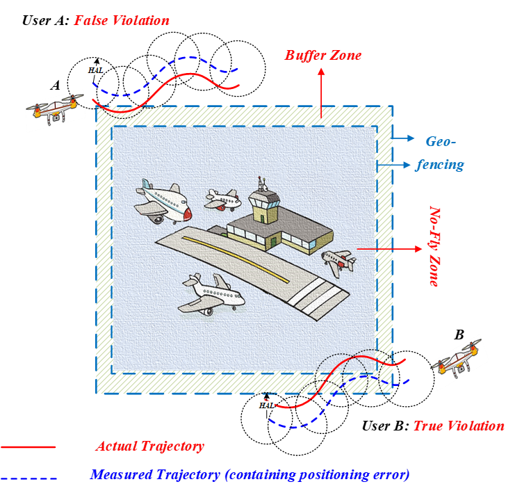
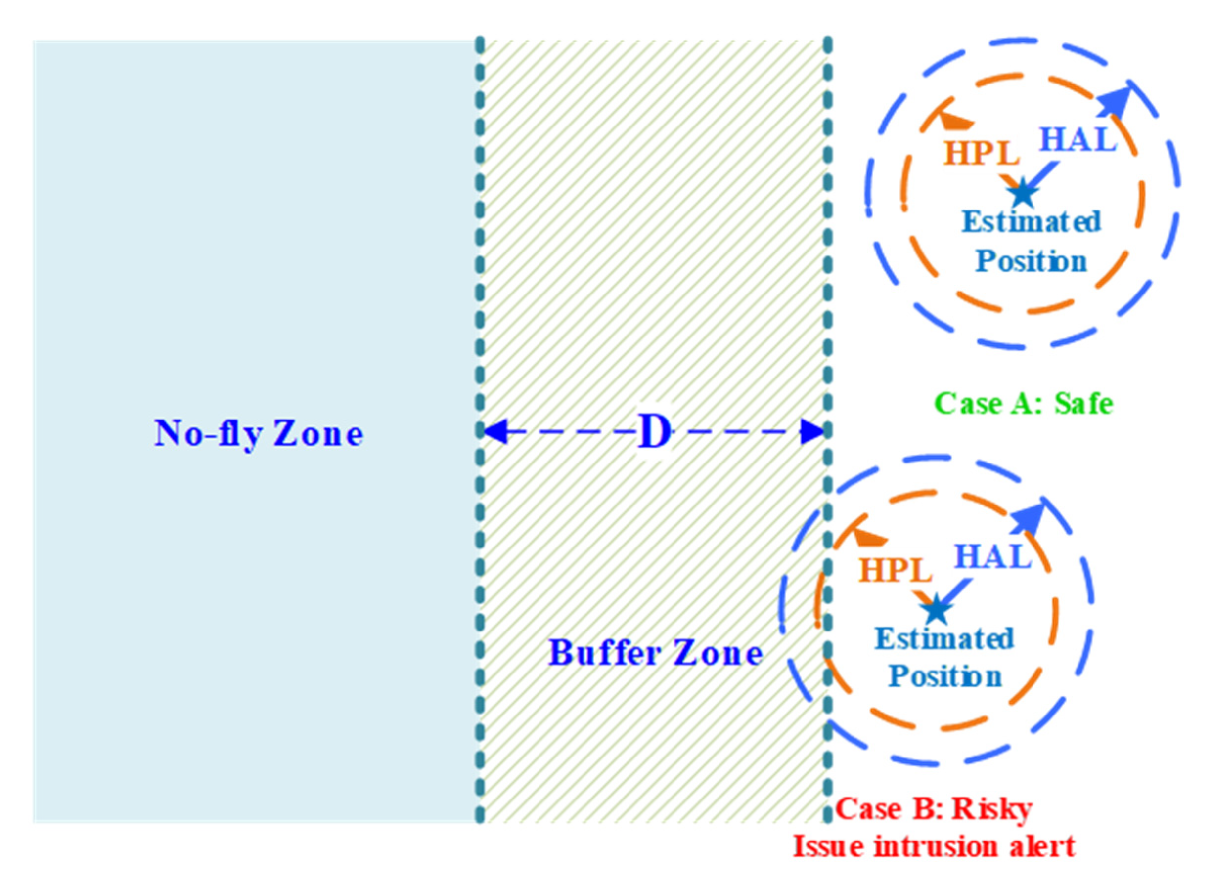
3. Concept and Requirement of No-Fly Zone Management
3.1. Concept of Location Based No-Fly Zone Management
3.2. Requirements at Service Level
3.3. Requirements at Positioning Level
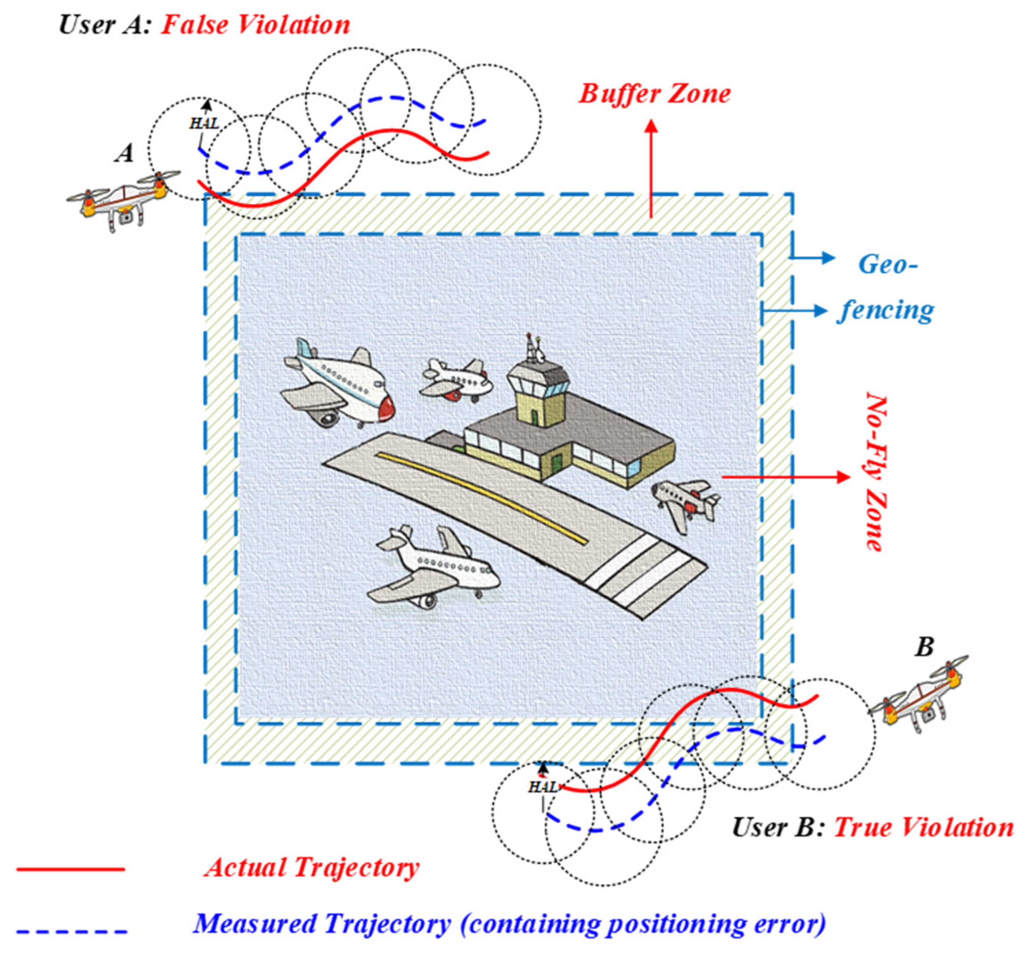
3.4. Requirements at Integrity Level
- Horizontal alert limit (HAL): this is the maximum horizontal position error () that must not be exceeded without issuing an alert to the user. A horizontal position failure (HPF) occurs when the exceeds the .
- Target integrity risk (): this is calculated by multiplying the probability of position failure and the probability of missed detection in Equation (1). is typically very low (e.g., 1E−7) for mission critical (e.g., safety of life) applications.
- Horizontal protection level (): the threshold value of the that satisfies the . Thus, should bound the position error in line with the . The probabilistic relationship is expressed as:
4. Integrated Navigation with Integrity Monitoring for the UAV No-Fly Zone Management
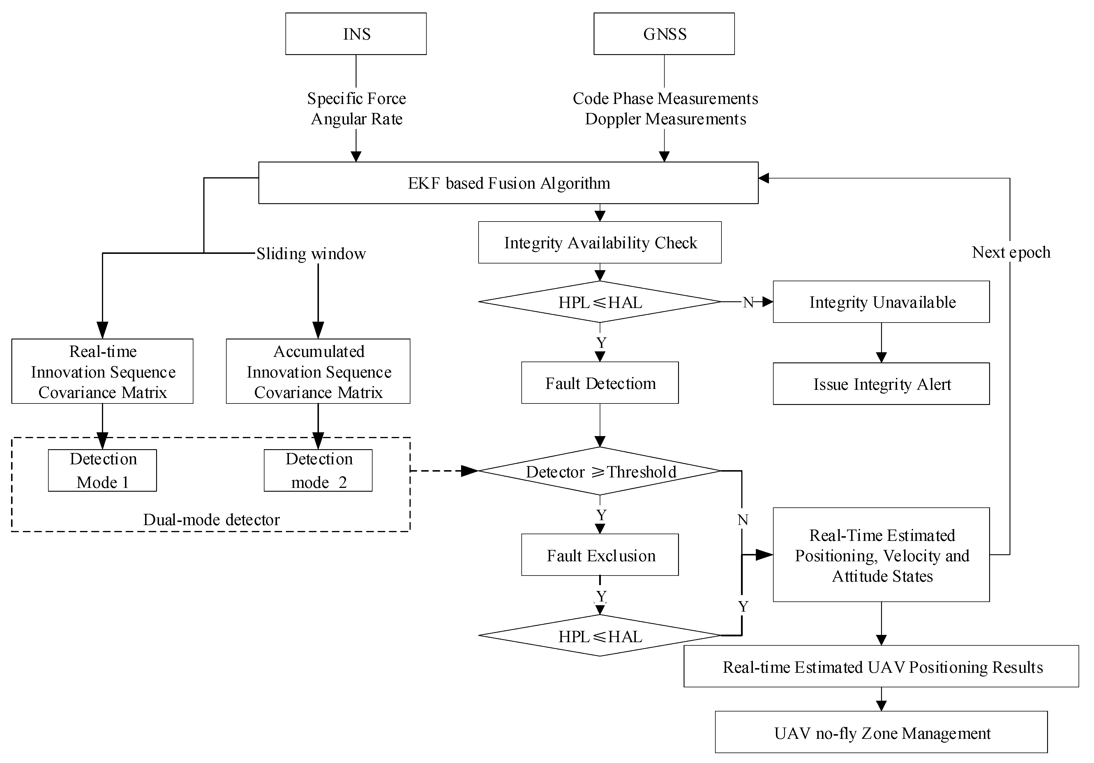
4.1. System Framework
4.2. Tightly Coupled GNSS/INS Integration
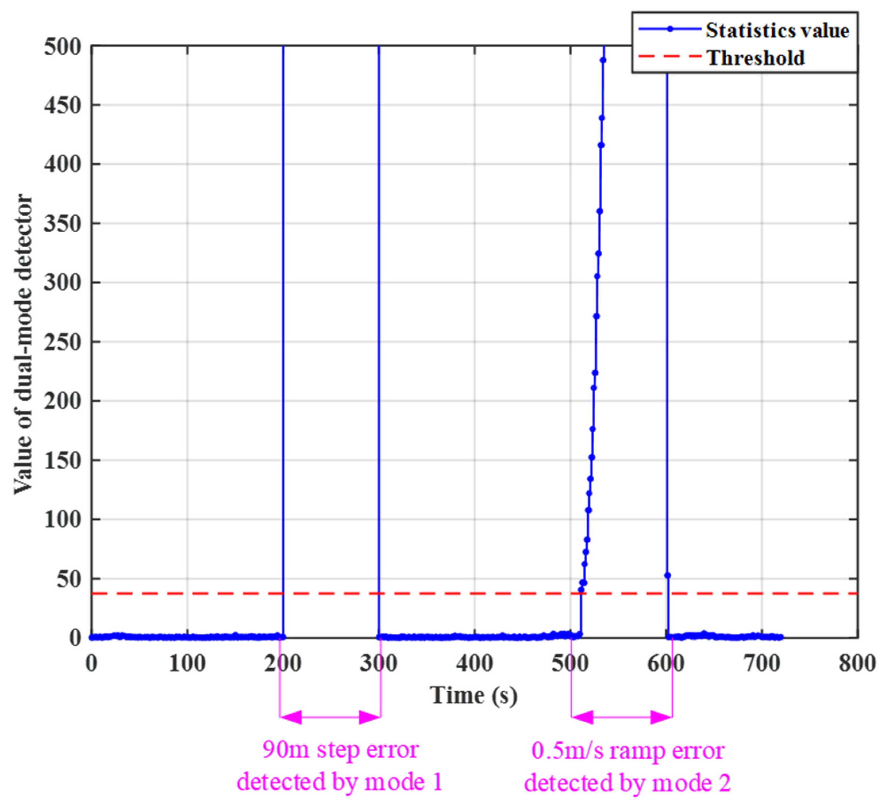
4.3. Integrity Monitoring Algorithm
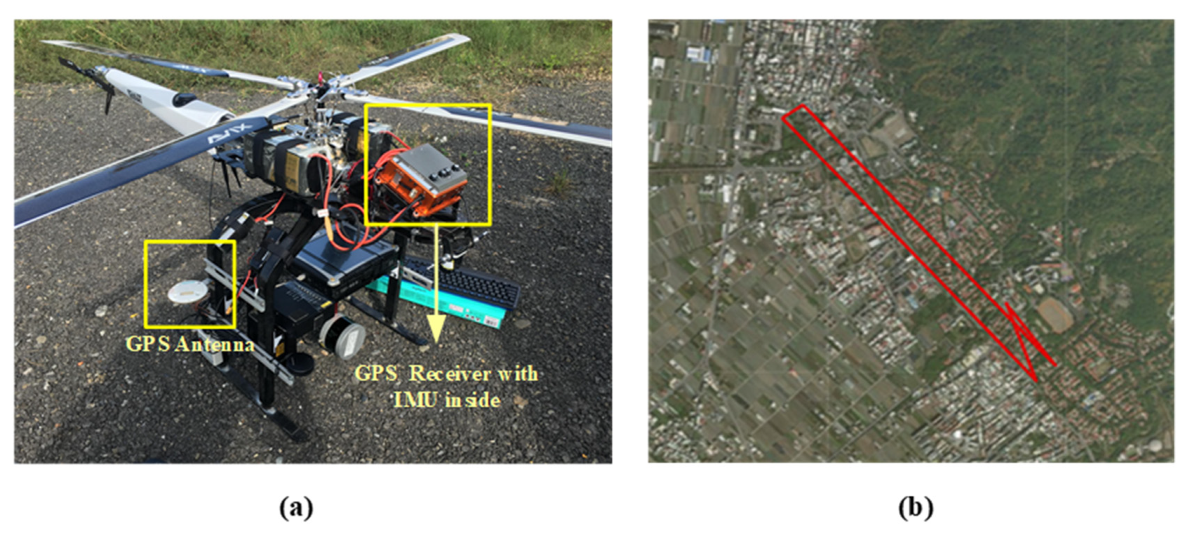
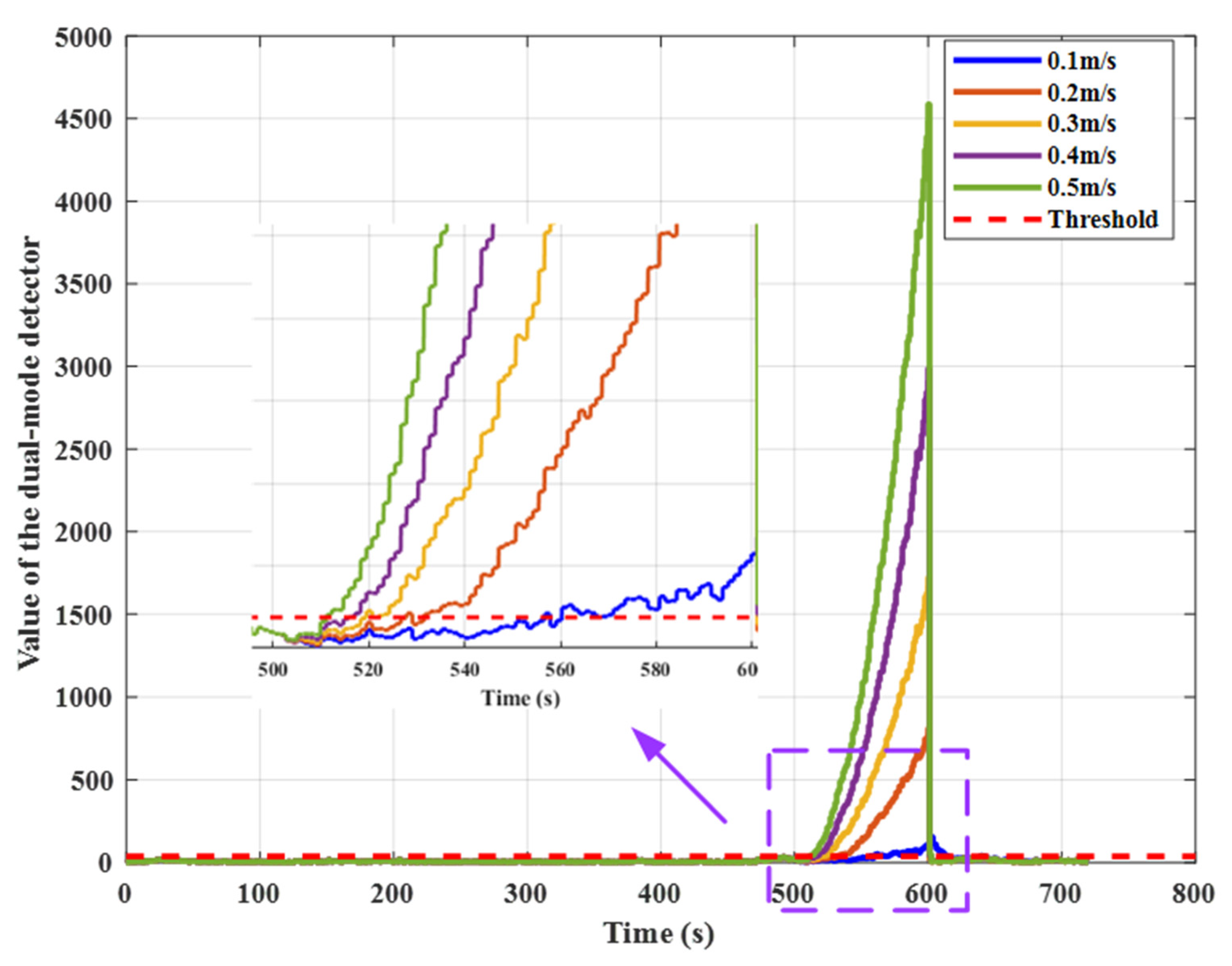
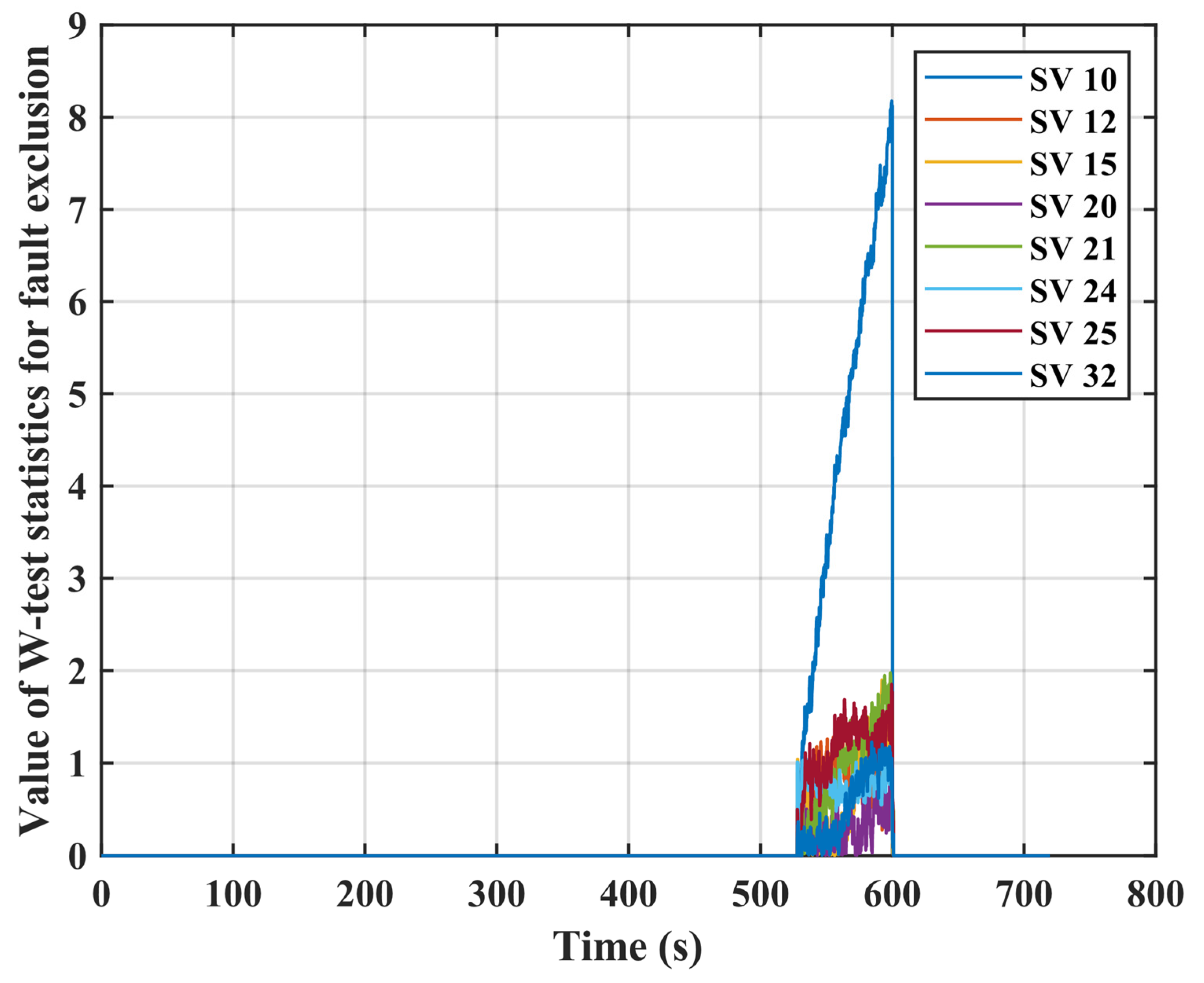
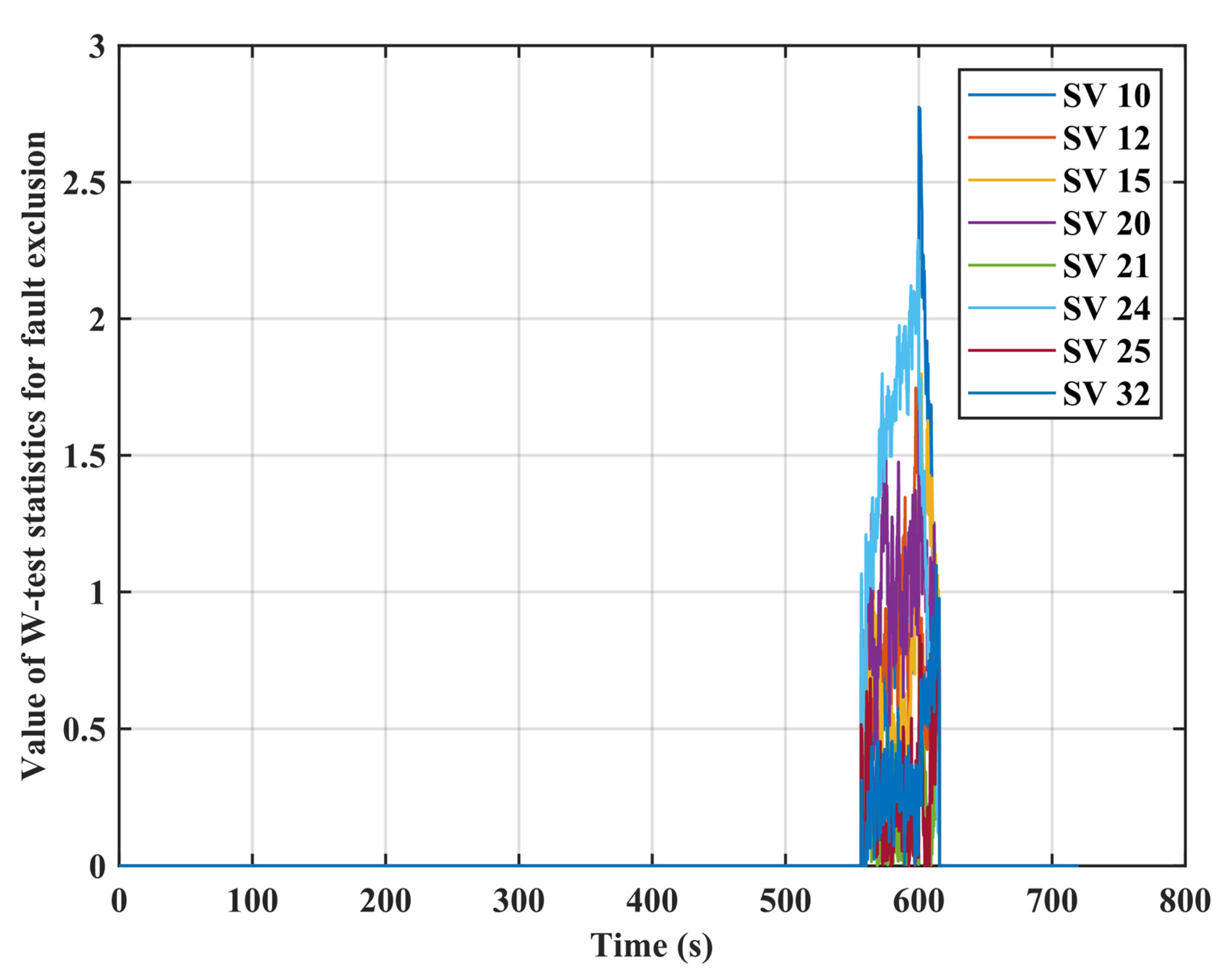
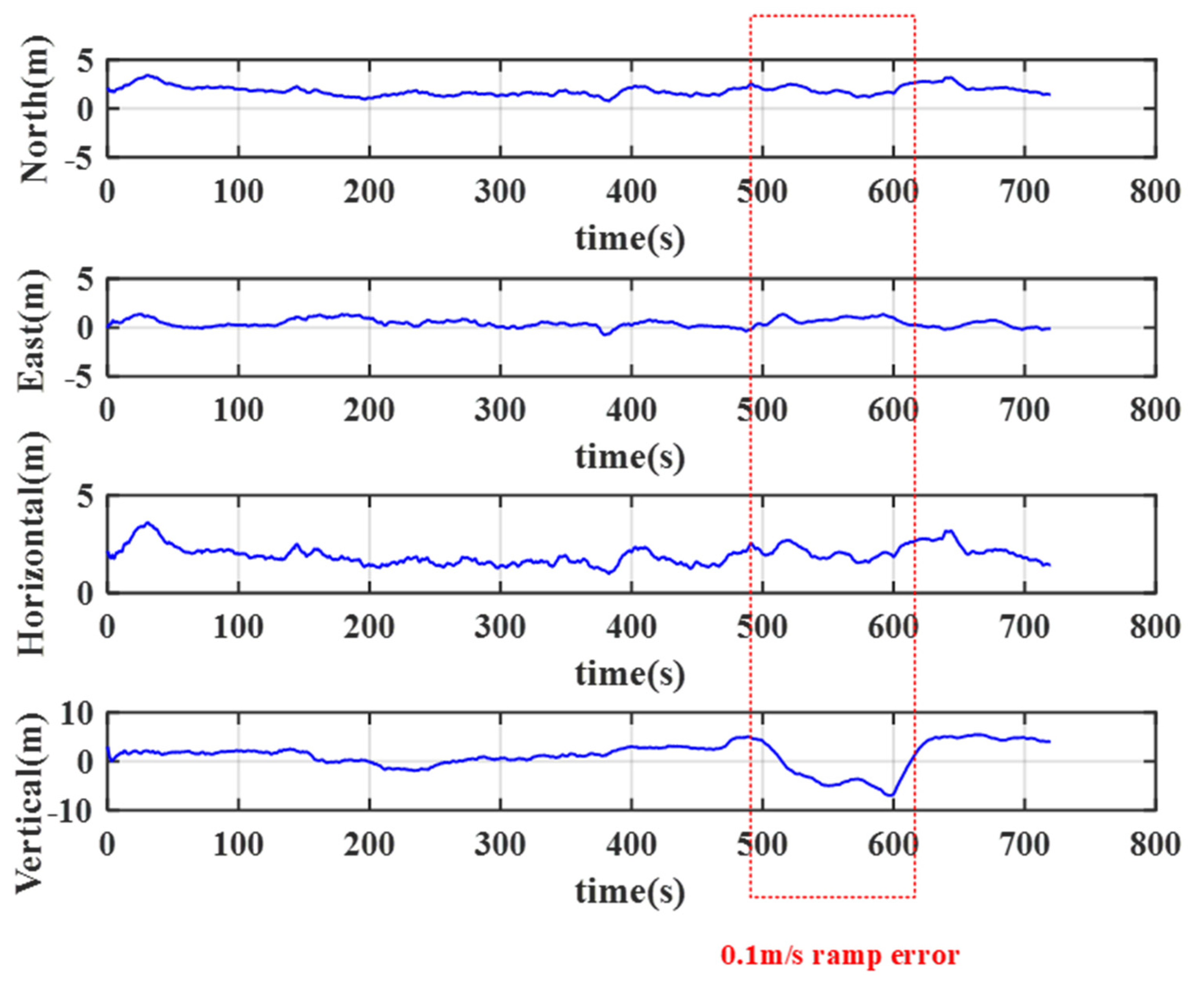
5. Field Test and Results Analysis
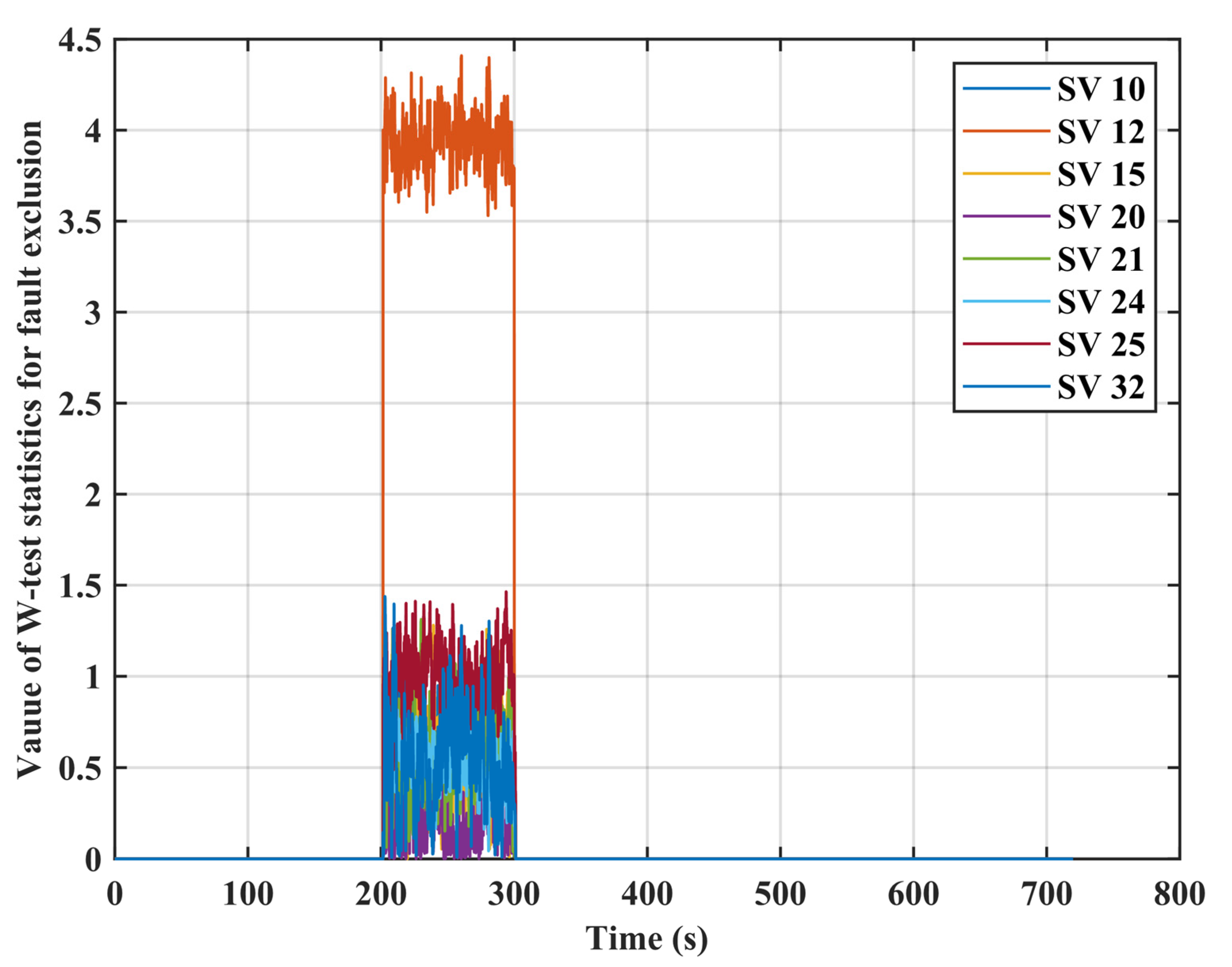
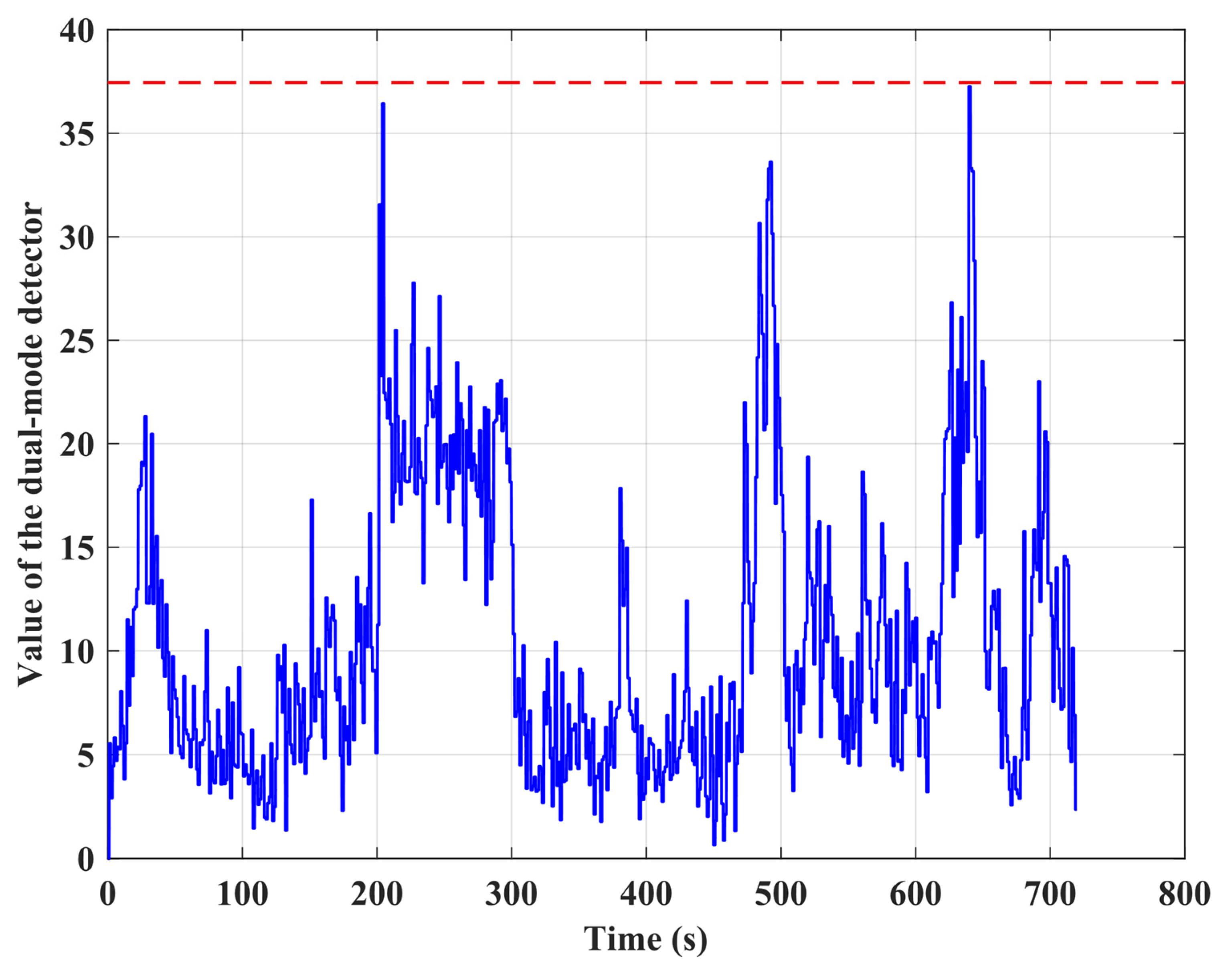
5.1. Data Collection and Sensitivity Analysis
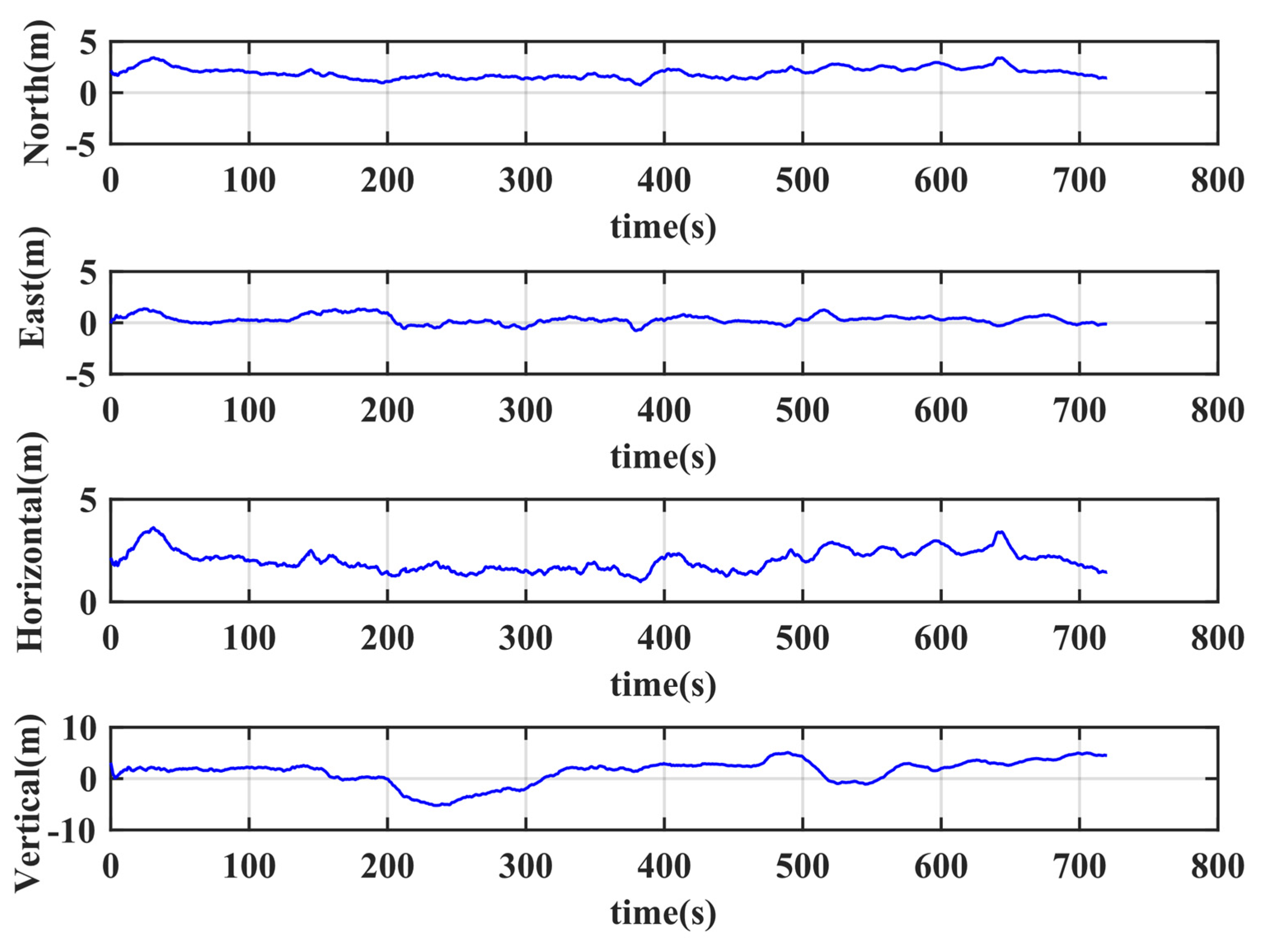
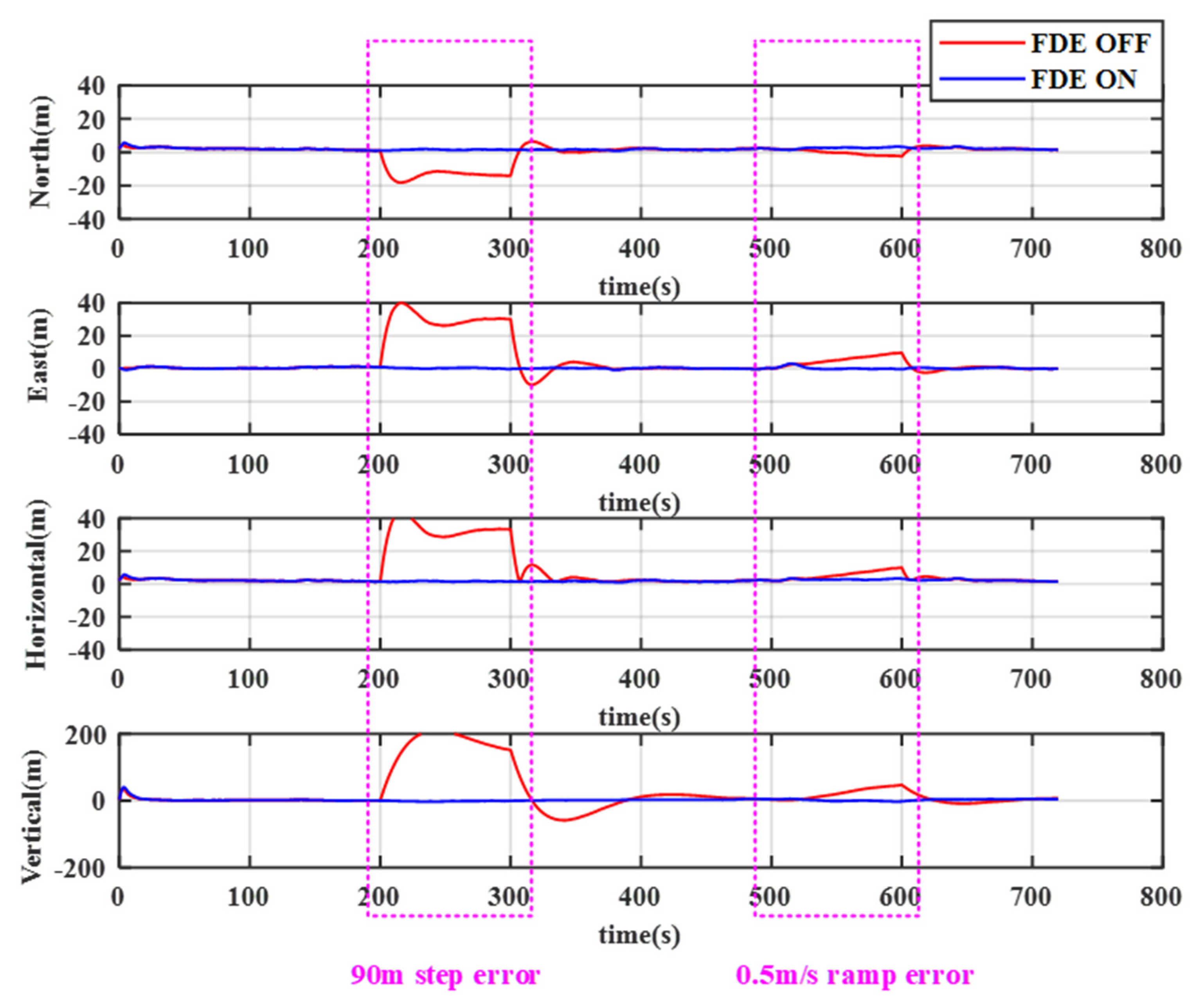
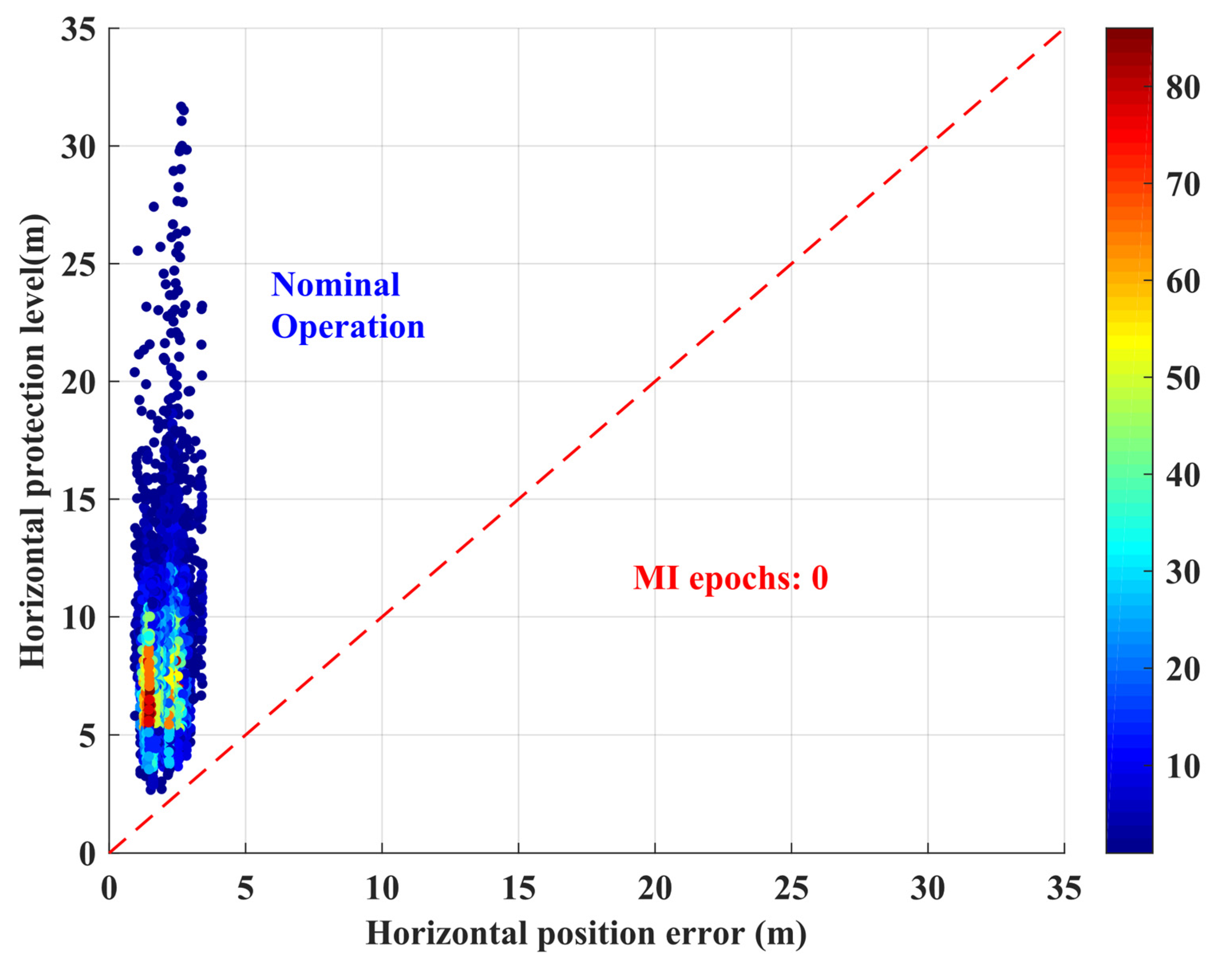
5.2. Results Analysis of the Positioning with Integrity Monitoring
6. Conclusions
Author Contributions
Funding
Acknowledgments
Conflicts of Interest
References
- Birnbaum, Z.; Dolgikh, A.; Skormin, V.; O’Brien, E.; Muller, D.; Stracquodaine, C. Unmanned Aerial Vehicle Security Using Recursive Parameter Estimation. J. Intell. Robot. Syst. 2016, 84, 107–120. [Google Scholar] [CrossRef]
- Kopardekar, P.H. Airspace Systems Program: Next Generation Air Transportation System Concepts and Technology Development FY2010 Project Plan Version 3.0. 2010. Available online: https://core.ac.uk/reader/10559957 (accessed on 4 January 2020).
- Bo, L.; Wei, G.; Xi, W.; Fu, X. Multi-UAVs Cooperative Area Search with No-Fly Zones Constraints. In Proceedings of the Control Conference, Hangzhou, China, 28–30 July 2015. [Google Scholar]
- Feng, S.; Ochieng, W.; Moore, T.; Hill, C.; Hide, C. Carrier phase-based integrity monitoring for high-accuracy positioning. GPS Solut. 2009, 13, 13–22. [Google Scholar] [CrossRef]
- Ochieng, W.Y.; Sauer, K.; Walsh, D.; Brodin, G.; Griffin, S.; Denney, M. GPS Integrity and Potential Impact on Aviation Safety. J. Navig. 2003, 56, 51–65. [Google Scholar] [CrossRef]
- Godha, S.; Cannon, M.E. GPS/MEMS INS integrated system for navigation in urban areas. GPS Solut. 2007, 11, 193–203. [Google Scholar] [CrossRef]
- Angelino, C.V.; Baraniello, V.R.; Cicala, L. UAV Position and Attitude Estimation Using IMU, GNSS and Camera. In Proceedings of the 15th International Conference on Information Fusion, Singapore, 9–12 July 2012. [Google Scholar]
- Itkin, M.; Kim, M.; Park, Y. Development of Cloud-Based UAV Monitoring and Management System. Sensors 2016, 16, 1913. [Google Scholar] [CrossRef] [PubMed]
- Prevot, T.; Rios, J.; Kopardekar, P.; Robinson, J.E., III; Johnson, M.; Jung, J. UAS Traffic Management (UTM) Concept of Operations to Safely Enable Low Altitude Flight Operations. In Proceedings of the 16th AIAA Aviation Technology, Integration, and Operations Conference on American Institute of Aeronautics and Astronautics, Washington, DC, USA, 13–17 June 2016. [Google Scholar]
- Damilano, L.; Guglieri, G.; Quagliotti, F.; Sale, I.; Lunghi, A. Ground Control Station Embedded Mission Planning for UAS. J. Intell. Robot. Syst. 2013, 69, 241–256. [Google Scholar] [CrossRef]
- Geng, L.; Zhang, Y.F.; Wang, J.J.; Fuh, J.Y.H.; Teo, S.H. Mission Planning of Autonomous UAVs for Urban Surveillance with Evolutionary Algorithms. In Proceedings of the 2013 10th IEEE International Conference on Control and Automation (ICCA), Hangzhou, China, 12–14 June 2013; pp. 828–833. [Google Scholar]
- Torens, C.; Adolf, F. Automated Verification and Validation of an Onboard Mission Planning and Execution System for UAVs. In Proceedings of the AIAA Infotech@Aerospace (I@A) Conference, American Institute of Aeronautics and Astronautics, Boston, MA, USA, 19–22 Augest 2013. [Google Scholar]
- Gautier, J.D. GPS/INS Generalized Evaluation Tool (GIGET) for the Design and Testing of Integrated Navigation Systems. Ph.D. Thesis, Harvard University, Cambridge, MA, USA, 2003. [Google Scholar]
- Bhatti, U.I. Improved Integrity Algorithms for the Integrated GPS/INS Systems in the Presence of Slowly Growing Errors. Ph.D. Thesis, Imperial College London, London, UK, 2007. [Google Scholar]
- Salos, D.; Macabiau, C.; Martineau, A.; Bonhoure, B.; Kubrak, D. Analysis of GNSS Integrity Requirements for Road User Charging Applications. In Proceedings of the 2010 5th ESA Workshop on Satellite Navigation Technologies and European Workshop on GNSS Signals and Signal Processing (NAVITEC), Noordwijk, The Netherlands, 8–10 December 2010; pp. 1–8. [Google Scholar]
- Lee, Y.C. Analysis of Range and Position Comparison Methods as a Means to Provide GPS Integrity in the User Receiver. In Proceedings of the 42nd Annual Meeting of The Institute of Navigation, Seattle, WA, USA, 24–26 June 1986. [Google Scholar]
- Parkinson, B.W.; Axelrad, P. Autonomous GPS Integrity Monitoring Using the Pseudorange Residual. Navigation 1988, 35, 255–274. [Google Scholar] [CrossRef]
- Sturza, M.A. Navigation System Integrity Monitoring Using Redundant Measurements. Navigation 1988, 35, 483–501. [Google Scholar] [CrossRef]
- Brown, R.G.; McBurney, P.W. Self-Contained GPS Integrity Check Using Maximum Solution Separation. Navigation 1988, 35, 41–53. [Google Scholar] [CrossRef]
- Brown, R.G. Solution of the Two-Failure GPS RAIM Problem under Worst-Case Bias Conditions: Parity Space Approach. Navigation 1997, 44, 425–431. [Google Scholar] [CrossRef]
- Rippl, M.; Spletter, A.; Günther, C. Parametric Performance Study of Advanced Receiver Autonomous Integrity Monitoring (ARAIM) for Combined GNSS Constellations. In Proceedings of the 2011 International Technical Meeting of The Institute of Navigation, San Diego, CA, USA, 24–26 January 2011. [Google Scholar]
- Blanch, J.; Walter, T.; Enge, P. Position error bound calculation for GNSS using measurement residuals. IEEE Trans. Aerosp. Electron. Syst. 2008, 44, 977–984. [Google Scholar] [CrossRef]
- Panagiotakopoulos, D.; Majumdar, A.; Ochieng, W.Y. Extreme value theory-based integrity monitoring of global navigation satellite systems. GPS Solut. 2014, 18, 133–145. [Google Scholar] [CrossRef]
- Escher, A.-C.; Macabiau, C.; Martin, N.; Roturier, B.; Vogel, V. GNSS/IRS Hybridization: Fault Detection and Isolation of More than One Range Failure. In Proceedings of the 15th International Technical Meeting of the Satellite Division of The Institute of Navigation, Portland, OR, USA, 24–27 September 2002. [Google Scholar]
- Diesel, J.; King, J. Integration of Navigation Systems for Fault Detection, Exclusion, and Integrity Determination—Without WAAS. Int. J. Res. Med. Sci. 1995, 1, 619–620. [Google Scholar]
- Lee, Y.C.; O’Laughlin, D.G. Performance Analysis of a Tightly Coupled GPS/Inertial System for Two Integrity Monitoring Methods. Navigation 2001, 47, 175–189. [Google Scholar] [CrossRef]
- Sun, R.; Zhang, Y.; Ye, B.; Ochieng, W.Y. A Required Navigation Performance Based Approach to Monitor the Accuracy and Integrity Performance of UAVs for Delivery Applications. In Proceedings of the China Satellite Navigation Conference (CSNC) 2018 Proceedings CSNC 2018, Harbin, China, 23–25 May 2018. [Google Scholar]
- Maybeck, P.S. Stochastic Models, Estimation, and Control; Academic Press: Washington, DC, USA, 1982; Volume 1. [Google Scholar]
- Hewitson, S.; Kyu Lee, H.; Wang, J. Localizability Analysis for GPS/Galileo Receiver Autonomous Integrity Monitoring. J. Navig. 2004, 57, 245–259. [Google Scholar] [CrossRef]


| System Detects a Violation Vvent | |||
|---|---|---|---|
| Yes | No | ||
| Actual violation event | Yes | Correct detection | Missed detection (True violation but not detected) |
| No | False detection (False violation) | Correct non-detection | |
| Number of Satellites-in-View | 1 | 2 | 3 | 4 | 5 | 6 | 7 | 8 |
|---|---|---|---|---|---|---|---|---|
| 19.51 | 23.03 | 25.90 | 28.47 | 30.86 | 33.11 | 35.26 | 37.45 |
| Scenarios | Fault Start Time (s) | Fault End Time (s) | Error Types | Error Sources |
|---|---|---|---|---|
| Scenario 1 | 200 | 300 | Step error | 10~90 m range error added to SV12 with an interval of 20 m |
| Scenario 2 | 500 | 600 | Ramp error | 0.1~0.5 m/s clock drift equivalent range error added to SV10 with an interval of 0.1 m/s |
| Error Source | Error Detected Time (s) |
|---|---|
| 10 m | 1.6 s |
| 30 m | 0.1 s |
| 50 m | 0.1 s |
| 70 m | 0.1 s |
| 90 m | 0.1 s |
| Error Source | Error Detected Time (s) |
|---|---|
| 0.1 m/s | 60.3 s |
| 0.2 m/s | 31.5 s |
| 0.3 m/s | 21.8 s |
| 0.4 m/s | 15.9 s |
| 0.5 m/s | 11.1 s |
| Direction | East | North | Horizontal | Vertical |
|---|---|---|---|---|
| RMSE (m) | 0.557 | 2.007 | 2.083 | 2.503 |
| 95% percentile (m) | 1.148 | 2.879 | 2.943 | 4.845 |
| MAX (m) | 1.468 | 3.404 | 3.498 | 8.857 |
© 2020 by the authors. Licensee MDPI, Basel, Switzerland. This article is an open access article distributed under the terms and conditions of the Creative Commons Attribution (CC BY) license (http://creativecommons.org/licenses/by/4.0/).
Share and Cite
Sun, R.; Zhang, W.; Zheng, J.; Ochieng, W.Y. GNSS/INS Integration with Integrity Monitoring for UAV No-fly Zone Management. Remote Sens. 2020, 12, 524. https://doi.org/10.3390/rs12030524
Sun R, Zhang W, Zheng J, Ochieng WY. GNSS/INS Integration with Integrity Monitoring for UAV No-fly Zone Management. Remote Sensing. 2020; 12(3):524. https://doi.org/10.3390/rs12030524
Chicago/Turabian StyleSun, Rui, Wenyu Zhang, Jiazhu Zheng, and Washington Yotto Ochieng. 2020. "GNSS/INS Integration with Integrity Monitoring for UAV No-fly Zone Management" Remote Sensing 12, no. 3: 524. https://doi.org/10.3390/rs12030524
APA StyleSun, R., Zhang, W., Zheng, J., & Ochieng, W. Y. (2020). GNSS/INS Integration with Integrity Monitoring for UAV No-fly Zone Management. Remote Sensing, 12(3), 524. https://doi.org/10.3390/rs12030524