Abstract
Dual one-way inter-satellite link (ISL) pseudoranges of BDS-3 satellites can be introduced as an additional measurement along with L-band pseudoranges and phases to improve the accuracy of precise orbit determination (POD). In the existing research, although the clock-free or geometry-free ISL observables are derived from the raw two one-way pseudoranges, only the clock-free observables are adopted for the ISL joint POD (Joint 1 POD) without considering the geometric-free observables. An improved joint (Joint 2 POD) strategy making full use of the clock-free and geometry-free observables is applied in this contribution. The orbits of ground-only POD, ISL-only POD, Joint 1 POD, and Joint 2 POD are comprehensively compared by the orbit overlapping differences, the Satellite Laser Ranging (SLR) residuals, and the characteristics of the satellite clock offsets estimated simultaneously. The comparisons prove that the performance of the Joint 2 POD strategy is better than that of the other three POD strategies regardless of the types of satellites. Moreover, this paper discusses ISL’s contribution to the station selection strategy in terms of the number and distribution. The experimental results show that, when there are more than 20 stations, each additional 10 stations contributes to a maximum of 7.5%, 3.9%, and 2.8% improvement on MEO, IGSO, and GEO satellites 3D accuracy, respectively. When the number of stations reaches 50, the precise orbits achieve similar accuracy to the results using 80 stations. In addition, after adding ISL data, the orbits estimated using 10 regional stations and 10 global stations are greatly improved, and the accuracy between them is only 0.9 cm in 3D errors.
1. Introduction
The third-generation BeiDou Navigation Satellite System (BDS-3), which is currently being deployed, is a global satellite navigation system. It is the third step of China’s satellite navigation construction. The complete BDS-3 constellation will consist of 24 satellites in three orbital planes in medium Earth orbit (MEO) with an orbit inclination angle of 55°; 3 satellites in geostationary Earth orbit (GEO) located at longitudes 80°, 110.5°, and 140°; and 3 additional satellites in inclined geosynchronous orbits (IGSO) with an inclination of 55° over the Asia-Pacific region [1,2]. By the end of 2019, 28 BDS-3 satellites have been launched into space.
BDS-3 adds three new frequencies to the regional BeiDou satellite navigation system (BDS-2) [3], and three types of BDS-3 satellites are given different functions. Due to the geostationary characteristics of GEO satellites and the resulting lower orbit accuracy, BDS-3 GEO satellites are mainly used to provide some featured services, such as satellite-based augmentation (SBAS), short message communication (SMC), and precise point positioning (PPP) [1]. The rest of the 24 MEO satellites and 3 IGSO satellites play a key role in providing the radio navigation satellite service (RNSS). However, the other side of the coin is that this hybrid constellation challenges precision orbit determination (POD) because MEO satellites require tracking stations distributed globally and IGSO/GEO satellites are only tracked by stations in the Asia-Pacific region.
The normal operation of navigation satellites is accomplished by means of continuous tracking and control by the ground segment. To get rid of the dependence on the ground-based support, GPS has utilized an ultrahigh-frequency (UHF) inter-satellite link (ISL) technology to achieve autonomous navigation since the GPS IIR satellites [4,5,6,7,8]. Research shows that autonomous navigation can maintain navigation accuracy for six months without ground contact [8]. For BDS, the monitoring stations are distributed in mainland China for various reasons. Once the satellite loses the ground contact, the satellite will not be controlled, and thus orbit and clock accuracy will drop sharply. Therefore, the new BDS-3 satellites are equipped with ISL payload following GPS. This new payload enables intel-satellite communication and ranging by the Ka-band signal, which is suffered from less multipath and noise issues. ISL can be used to route the data from satellites out of the coverage region to satellites that are within the coverage region. Benefit from these new payloads, the satellite running outside mainland China can also be tracked and controlled indirectly. The operational control system (OCS) can make full use of both L band signals and Ka-band signal observations to generate the broadcast messages and to update messages [9].
Moreover, the ISL payloads provide BDS-3 with the potential for autonomous navigation. Many results of the BDS-3 experimental or BDS-3 satellites orbit determination with the real ISL measurements are published. Ren et al. discussed the orbit determination with prior orbit constraints [10]. Yang et al. presented a detailed evaluation of the combined orbit determination method, which indirectly achieves a 37–95% improvement in the orbit-only signal-in-space range error accuracy [11]. Tang et al. applied the ISL data from BDS experiment satellites on the centralized autonomous orbit determination [12]. Ren et al. analyzed the application of batch processing and extended Kalman filtering algorithm on BDS autonomous navigation [13]. Guo et al. proposed an onboard extended Kalman filter constrained with high predicted orbit inclination and longitude of ascending node to resolve the constellation rotation error issue [14].
Precise orbit is the key to high-precision positioning applications and related scientific research. The other advantage of ISL is that the accuracy of the BDS-3 satellite orbit can be improved by using both ISL and L-band measurements. Xie et al. used 16 global distributed stations and 6 China regional stations to verify the improvement of orbit determination accuracy when adding ISL measurement and finally achieved a great improvement of 42% and 83%, respectively [15]. Yang et al. explored that with the help of ISL, the 3D root mean square (RMS) of eight satellites orbit position computed using 10 regional stations was decreased from 1 to 0.5 m [16]. In general, orbit accuracy at the few decimeters level could be achieved by the different studies.
Nevertheless, there are still many aspects of BDS-3 ISL that have not been studied. For example, there are two ISL observation models applied for joint POD using ISL and ground-tracking data. One is to treat a pair of raw one-way ISL pseudoranges as two independent observables [17], and the other is to derive the ISL clock-free observables from a dual one-way pseudoranges [2,11,15,18]. These derived clock-free observables contain only geometric information, so the observation model excludes the satellite clock offset parameters. In the case of joint POD, it is unreasonable to use only the clock-free observables. Because the satellite clock offsets and the orbit in the radial component are highly correlated in the L-band POD results [19], the addition of ISL data can reduce the orbit impact on the estimation of satellites clock offsets and adjust the clock parameters. Besides, as more and more receivers are upgraded, more than 100 ground tracking stations have access to receive the signal broadcast by BDS-3 satellites. Considering the addition of a large amount of ISL data, there will be a lot of L-band redundant data for joint orbit determination, which cannot contribute to the accuracy, but reduce the calculation efficiency. On the other hand, since BDS-3 is a hybrid constellation, the distribution of stations required for the POD of satellites operating in different orbital planes is not the same. The addition of ISL measurements can optimize the geometry of the observation model. Therefore, further research is needed to explore whether the introduction of ISL to joint POD has requirements on the distribution of stations.
This article continues to analyze the issue of ISL’s contribution to the joint POD. An improved joint POD strategy using ground-tracking and ISL observations of the BDS-3 satellites is applied. This strategy makes full use of both clock-free and geometry-free ISL observables derived from the raw dual one-way ISL observations, which has not been used by previous studies. The satellite orbit parameters, as well as satellite clock offsets estimated at the same time, are evaluated and compared. Through this improved strategy, the ISL’s contribution to joint POD in the case of the selection of stations, including the distribution of stations and the number of stations, is analyzed separately for three types of BDS-3 satellites.
2. Methodology
The topology of the BDS-3 satellite links is a dynamic network. Based on a pre-designed timeslot scheduling, a satellite can establish a connection with another satellite in 3 s following a time division multiple access (TDMA) scheme. Since the round-trip measurement period is short, the dual one-way pseudoranges are usually normalized to the same reference time to derive geometry-free or clock-free observables. Once the derived observables are obtained, joint orbit determination can be performed with L-band code and phase measurements.
2.1. Dynamic Inter-Satellite Network
ISL measurement is a dual one-way observation generated by a pair of satellites. The two satellites are each other’s transmitter and receiver. The phased array antenna equipped on BDS-3 satellites can realize the beam scanning in a wide space range of −60° to 60° [15]. The pointing agility and fast-tracking characteristics of phased array antenna make it possible to complete dual unidirectional ranging in a short time of 3 s, which can establish a dynamic inter-satellite network [20]. Phased array antennas work following predesigned timeslot schedule by ground control personnel. The timeslot schedule records the chain building information for a week, including when and how one satellite connects with the other satellites.
The timeslot schedule of the BDS-3 ISL takes 1 h as a pre-designed period. Each pair of satellites is assigned a short-time segment of 3 s to finish a dual one-way ranging. A forward link is established in the first 1.5 s, and a backward link is established in the second 1.5 s [20]. Therefore, a satellite can establish contact with up to 20 satellites or anchor stations in one minute without regard to visibility. In the following 59 min, the order and rules for establishing the links remain the same as in the first minute.
2.2. L-Band Observation Model
Both carrier phase measurements and the code measurements are adopted in the POD processing. Ionospheric-free (IF) combination is used to remove the first-order ionospheric effect. The L-band observation equations about IF phase measurements and code measurements are expressed as
where is the distance from the satellite j to the L-band antenna phase centers of the receiver k; and are satellite and receiver clock offset, respectively; is the non-dispersive tropospheric delay in zenith direction, which can be mapped to satellite-to-receiver direction by multiply the mapping function ; C is the light speed; is the wavelength of the IF observation and is the corresponding ambiguity; and and represent the receiver noise of code and phase measurement, respectively.
2.3. Ka-Band Observation Model
As a pair of one-way pseudoranges, ISL measurement can be used alone or along with L-band data to determine satellite orbits and clock offsets. Suppose that satellite A receives the Ka-band signal transmitted by satellite B at time t1 and generates the observation and satellite B receives the Ka-band signal transmitted by satellite A at time and generates the observation . Then, the Ka-band observation model can be formulated as
where and is the Ka-band satellite antenna phase center vectors in Cartesian coordinates at the certain observation epoch; and are satellite clock offset; and are the transmitting hardware delay; and are receiving hardware delay; C represents the speed of light; and refer to corrections that can be easily modeled for the measurement, such as relativistic effects and Ka-band phase center offsets; and and are the measurement noises.
We can treat them as two independent one-way observations and model them directly similar to the L-band pseudoranges [17], or we can transform a pair of one-way observations to two observations at the same time for processing, as
where
and the correction and can be computed with broadcast messages following:
The accuracy of and depends on the changing rate of satellite orbit and clock offsets computed by broadcast messages, and the accuracy loss is much smaller than the ISL residuals, which can be ignored in a short time [11]. Obviously, the sum and difference of Equations (7) and (8) are equal to
Compared to the L-band observation model expressed by Equations (1) and (2), the clock offsets or geometry distance are removed in Equation (11) or Equation (12). This feature allows us to perform POD or clock offsets estimation separately. It is very meaningful for clock characteristic evaluation. In the past, the satellite clock offsets computed by the L-band data contained unmodeled orbit errors, which affected the evaluation results. Through the geometry-free Equation (12), the influence of the orbit error on the clock offsets will be greatly eliminated. In the previous studies about BDS-3 POD, only Equation (11) is adopted in Ka-band POD. Therefore, the information and functional relationship implied in Equation (12) are rudely discarded. The improved joint POD method in this paper makes full use of both geometry-free Equation (11) and clock-offsets-free Equation (12) to achieve joint orbit determination.
2.4. Processing Strategy
Four POD modes, namely ground-only POD, ISL-only POD, Joint 1 POD, and Joint 2 POD, are utilized to analyze the contribution of BDS-3 ISLs to orbit determination in this research. For ground-only POD, the code and carrier measurements in ionosphere-free combination expressed as Equations (1) and (2) are adopted. For ISL-only POD, only the clock-free pseudoranges described as Equation (11) are used. In particular, only in this mode, two ground anchor stations are added to reduce the constellation rotation resulting from the ISL-only POD [8,12,21]. For the Joint 1 POD, only ISL clock-free observations (Equation (11)) along with the IF code and carrier measurements (Equations (1) and (2)) are adopted. The improved joint POD applied in this contribution is expressed as Joint 2 POD, and the IF code and carrier measurements (Equations (1) and (2)) along with ISL geometry-free and clock-free observations (Equations (11) and (12)) are used simultaneously to determine the precise orbit and clock parameters as well as other relevant parameters. Some necessary correction models and settings of L-band and Ka-band observation are summarized in Table 1.

Table 1.
Processing strategy for the POD.
It is important to emphasize the differences between the observables of L-band and Ka-band. First, the different types of observations have different weight settings. A prior standard deviation for the raw L-band phase, code, and Ka-band measurements are 0.002, 0.2, and 0.5 m, respectively. After that, the final weight of L-band observations needs to be adjusted according to the satellite elevation, while the weight of the Ka-band is independent of the satellite nadir angle. Second, although a pair of one-way ranging is completed at a 3-s interval, the observables are still transformed to the reference time with a sampling interval of 300 s, which is to maintain consistency with the L-band data to facilitate the estimation of the satellite clock offsets. However, due to the accuracy of broadcast ephemeris, the precision of the transformation (Equations (9) and (10)) is limited by the length of the extrapolation time of reference epoch in the broadcast ephemeris, thus only the ISL data in a 120-s time window centered on the reference time are utilized [15]. Moreover, for ISL data, the ionosphere delay is negligible because of the high frequency (23 GHz) of the Ka-band and the low electron density on the signal propagation path. Similarly, there is no need to consider tropospheric correction, if there are no ISL measurements with regard to anchor stations. Besides, the L-band antenna phase center offset (PCO) values are provided by the BDS official website while the Ka-band PCO values are provided by manufacturers.
Four groups of precise BDS-3 orbits are processed by revised PANDA software [28], which has an additional function of outlier detection and adjustment for ISL data. The procedure of the Joint 1/2 POD can be divided into three steps. First, the POD using ground code and phase observation is carried out. This step is mainly to eliminate the L-band abnormal data and detect carrier cycle slips. Then, the broadcast orbit is used as a reference for detecting outliers in the ISL data through Equation (11). Once the above two steps are completed, the derived ISL measurements will be added to the least squares to estimate the orbital and clock parameters together with L-band measurements. After a few iterations of least squares adjustment, the orbital parameters along with satellite clock and other estimated parameters can be obtained.
The general method to evaluate the internal consistency of satellite orbits is the direct comparison of positions from different orbit solutions, e.g., the last two days of a three-day arc with the first two days of the next three-day arc. The residuals are usually given in a satellite-centered orbit system in along-track, radial, and cross-track directions. Besides, the Satellite Laser Ranging (SLR) data can be used as an independent tool to evaluate orbit accuracy.
2.5. Data Collection
The experimental data of BDS-3 satellites come from a total of 80 MGEX and iGMAS ground stations and 190 pairs of satellite-to-satellite links during the period of day-of-year (DOY) 198–280 in 2019. The distribution of these stations is marked in Figure 1. Note that during this period only 21 BDS-3 satellites were in orbit, including 18 MEO satellites, 2 IGSO satellites (C38 and C39), and 1 GEO satellite (C59). However, the IGSO and GEO satellites are still in a test stage, during which the signal can only be decoded by the iGMAS receivers. The observation of satellite C39 started from DOY 227. A brief comparison of the amount of two types of measurements in BDS Week 715 (DOY 251–257) is plotted in Figure 2 as an example. Figure 2a shows the number of available one-way ISL measurements in pairs, where the outliers and single one-way observations that cannot form a dual one-way link are discarded. Figure 2b shows the number of available code/phase measurements after screening outliers and deleting short arcs less than 1200 s. It is obvious that there are many more ISL data than L-band measurements despite the different types of orbits. The number of L-band measurements of IGSO and GEO satellites is less than that of MEO satellites.
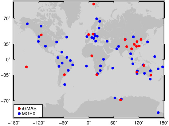
Figure 1.
Distribution of 80 MGEX (blue dot) and iGMAS (red dot) stations.
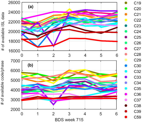
Figure 2.
Number of available data in BDS Week 715: (a) the number of dual one-way ISL measurements, where outliers and single one-way observations that cannot form a dual one-way link are discarded; and (b) the number of code/phase measurements, where outliers and observations of short arcs less than 1200 s are discarded.
3. POD Results
In this section, the orbits estimated by the Joint 2 POD method are presented and compared with other POD methods, in order to analyze the ISL’s contribution to the orbit determination. Then, we discuss the enhancement of introducing ISL in the selection of L-band tracking stations, including the distribution of stations and the number of stations.
3.1. Comparison among Different POD Strategies
According to the four POD modes mentioned above, the precise orbits derived from three-day arcs are estimated. The two-day overlapping differences between two adjacent three-day solutions in along-track (A), radial (R), and cross-track (C) direction are used to evaluate the internal consistency of the orbits. The RMS results of MEO and IGSO satellites are presented in Figure 3, and the RMS value along with the errors of GEO satellites C59 are listed separately in Table 2 because they are much larger than those of MEO and IGSO satellites.
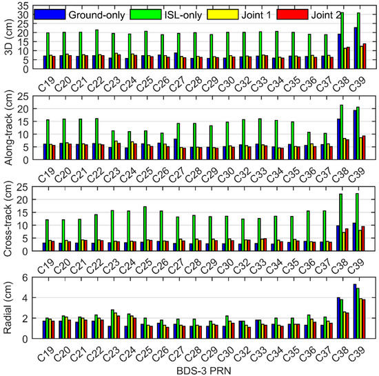
Figure 3.
Comparison of two-day arc overlapping difference of ground-only orbit, ISL-only orbit, Joint 1 orbit, and Joint 2 orbit based on MEO/IGSO satellites three-day arcs solution.
Table 2.
RMS of two-day arc overlapping difference of ground-only orbit, ISL-only orbit, Joint 1 orbit, and Joint 2 orbit based on three-day arcs solutions according to the satellite type.
According to Figure 3 and Table 2, it can be found that the addition of ISL data has a positive effect on the orbit determination. For the ground-only POD, the overlapping accuracy of MEO satellites is similar to that of Joint 2 POD and higher than Joint 1 POD because there are currently enough globally distributed ground stations to observe MEO satellites. On the other hand, the overlapping errors as an indicator of internal coincidence precision reflect the internal consistency of the orbit estimates, not the true accuracy. Besides, the improper weight of ISL data may also affect the contribution of ISL data on joint orbit determination, which needs further research in the future. Different from MEO satellites, the IGSO satellites can only be observed by iGMAS stations located in the Asia-Pacific region during the evaluation period. Therefore, the accuracy of Joint 2 has been significantly improved by 38.8% and 43.5% after adding ISL data for satellites C38 and C39, respectively. As a GEO satellite, satellite C59 has the characteristic of geostationary and high orbit height, and it can only be tracked by ground stations near the Asia-Pacific region similar to IGSO satellites. With the help of ISL, the weak geometry of the GEO satellite is strengthened, and the number of measurements is increased. Compared with ground-only results, the Joint 1/2 orbit accuracy of satellite C59 is greatly increased by 79.6%. As for ISL-only POD results, the orbit accuracy for the GEO satellite is greatly improved compared to the orbits obtained by ground-only POD strategy. It is noted that the ISL-only POD errors of the whole constellation in the along-track and cross-track direction are larger than those of the ground-only POD, except for the along-track direction of GEO satellites, which may be caused by the weaker orbital orientation constrain from only two anchor stations [12].
For the two different joint POD results, the Joint 2 orbits show a radial improvement of 10%, 2.5%, and 1.4% for MEO, IGSO, and GEO satellites, respectively, compared to the Joint 1 orbit. As a result, the 3D accuracy of MEO has increased by 9%. However, in the case of IGSO and GEO satellites, the addition of ISL clock information increases the errors in the cross-track or along-track direction and even leads to a decrease of 8.5% in the 3D accuracy of the IGSO satellites. Considering the fact that the IGSO and GEO satellites are still in the test phase and there is no measurement observed from stations other than iGMAS stations, a further study on the orbit differences between the two joint POD method needs to be carried out in the future.
The SLR data can be used as a reliable independent tool to evaluate orbit accuracy. At present, there are only four MEO satellites that are regularly tracked by International Laser Ranging Service (ILRS) [29,30]. The residuals (observed minus computed) are presented in Table 3. It follows that the ISL-only orbits have the worst standard deviations (STDs) while the ground-only orbits have the largest biases in the SLR residuals. When using both L-band and Ka-band data, the SLR residuals are significantly reduced. The RMS of the Joint 2 results is 8% smaller than that of the Joint 1 results.
Table 3.
SLR residuals to BDS-3 MEO satellites derived from ground-only orbit, ISL-only orbit, Joint 1 orbit, and Joint 2 orbit based on three-day arcs.
Since the orbit radial component is highly correlated with the clock offset parameters, the performance of the satellite clock offset estimated with the orbit parameters at the same time can also be used as an indicator to evaluate the accuracy of the orbits. Note that the ISL-only strategy does not solve the clock offset parameter. The clock overlapping differences of the two-day arc are computed based on two adjacent three-day arcs, and the RMS value is plotted in Figure 4. It can be found that the performance of the MEO satellite clock offsets became worse when applying the Joint 1 strategy, but the accuracy of clock offsets computed by the Joint 2 strategy shows a better performance than that of the ground-only strategy with an improvement of 27.0%, 49.5% and 122.3% for MEO, IGSO, and GEO satellites, respectively.
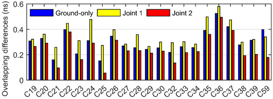
Figure 4.
Two-day overlapping differences of clock offsets estimated by ground-only POD, Joint 1 POD, and Joint 2 POD.
Existing studies have shown that the orbit error contained in the clock offsets estimated by L-band observations can be observed in the Allan variance [31], while the application of ISL-only measurements can reduce this error in clock offsets [32]. Further analysis of the stability characteristic of the satellite clock is shown in Figure 5. The overlapping Allan deviation values are computed by the satellite clock offsets that have been detrended by removing a daily quadratic trend. In the case of MEO satellites, the obtained clock stability of the two joint POD with ISL is improved compared to the ground-only clock. The bumps at around 10,000–20,000 s that are usually caused by the orbit errors lying in the ground-only clock offsets become much smoother in the results of the Joint 2 solutions. For the IGSO and GEO (C59) satellites, the stability derived from the Joint 2 clock is greatly improved compared to the other POD strategies. It is noted that the clock stability of satellite C59 obtained by the Joint 1 POD without geometry-free observables shows unexpected worse performance than that of the ground-only POD. Therefore, the performance of the satellite clock offsets estimated by the Joint 2 strategy indicates the rationality and necessity of adding both clock-free and geometry-free ISL observables.
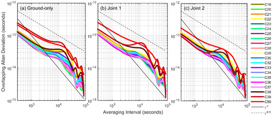
Figure 5.
Overlapping Allan deviation of the satellite clock offsets estimated by: ground-only POD (a); Joint 1 POD (b); and Joint 2 POD (c).
Although the accuracy of IGSO and GEO satellites using Joint 2 strategy is slightly worse than that of the Joint 1 strategy on the basis of the orbit overlapping differences, which only represents an internal consistency accuracy, the radial component in orbit overlapping differences, the SLR residuals and the characteristic of satellite clock offsets demonstrate that the orbit determination accuracy of the Joint 2 POD strategy is higher than that of Joint 1 POD. In the following sections, the Joint 2 POD strategy is adopted for three types of BDS-3 satellites to analyze whether the number of stations required for orbit determination can be reduced and whether the influence of stations distribution can be reduced or even eliminated after the introduction of ISL.
3.2. Impact of the Number of the Ground Stations
The number of ground tracking stations is crucial for the quality of POD results. On the one hand, sufficient tracking measurements are the guarantee of the accuracy of POD. On the other hand, redundant data will not improve calculation accuracy but will reduce calculation efficiency. As a rule of thumb, with 50 stations, an orbit with satisfactory accuracy can be determined [33]. Under the premise of high POD accuracy, we select different station networks to analyze whether the addition of ISL data can reduce the dependence of POD on the number of ground stations. These tracking station networks consist of different numbers of stations that are evenly distributed globally. With 10 stations as a unit interval, the number of stations is increased from 10 to 50 for the orbit determination. Different networks of tracking stations marked with different colors are plotted in Figure 6.
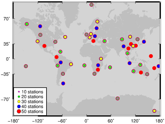
Figure 6.
Distribution of stations with different station selection schemes. Purple, green, yellow, blue, and red represent different tracking networks.
The overlapping orbit errors of BDS-3 satellites are plotted in Figure 7. The 3D errors of three types of satellites show an expected trend, that is, the more stations used, the higher the obtained accuracy. The accuracy of orbits obtained using 50 stations is similar to the accuracy of the results from 80 stations (see Figure 3). By using more stations, visible improvement is found in the along-track and cross-track directions, while the radial accuracy of these three satellites does not show much change. More importantly, according to the slope of the broken line in Figure 7, it can be inferred that the orbit accuracy changes most when the number of stations decreases from 20 to 10.
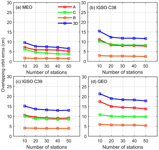
Figure 7.
Comparison of BDS-3 orbit accuracy obtained with different station selection schemes for” MEO satellites (a); IGSO satellite C38 (b); IGSO satellite C39 (c); and GEO satellite C59 (d).
Table 4 lists the improvement percentage of orbit accuracy obtained by increasing the number of tracking stations. For MEO satellites, the subsatellite points fall between 55° N and 55° S on the ground, thus increasing the number of global tracking stations can continue to improve the orbit accuracy, especially when the number of stations increases from 10 to 20 (19.7%) and from 40 to 50 (7.5%). With regard to GEO and IGSO satellites, since the subsatellite points are only over the Asia-Pacific region, the addition of globally distributed stations contributes to a slight improvement in orbit accuracy. Starting with 20 stations, each additional 10 stations bring a maximum of 3.9% improvement in the 3D RMS. Therefore, with the supplement of sufficient ISL data, an appropriate ground tracking network should be selected for the three types of satellites according to the required accuracy, which can improve the calculation efficiency of POD and ensure accuracy.
Table 4.
Percentage improvement when increasing the number of tracking stations.
3.3. Improvement on POD Using Regional Stations
At present, the ground facilities of the BDS are all located in China. To verify the ISL improvement on POD when using only regional stations, which is crucial to the generation of broadcast ephemeris, a regional tracking network consisting of seven stations in China and three stations in Australia is selected. The results with or without ISL data are compared to precise orbits obtained from 10 globally distributed stations. The distribution of regional and global tracking stations, as well as the subsatellite points of three types of satellites, are plotted in Figure 8 in which the red dots represent regionally distributed stations and the green dots represent globally distributed stations.
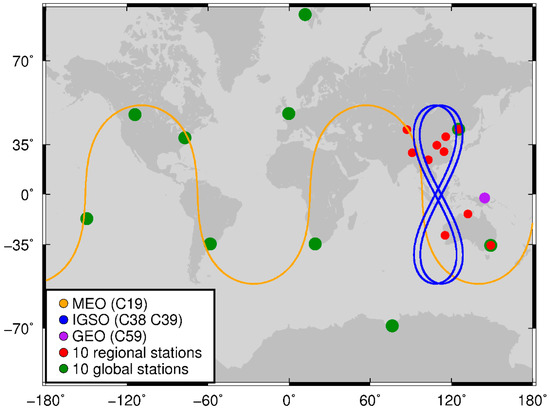
Figure 8.
Distribution of 10 regional stations (red dots) and 10 global stations (green dots). The subsatellite points of three types of satellites are marked as orange, blue, and purple, respectively.
Figure 9 shows the comparison between the orbits estimated with different tracking networks, based on the two-day overlapping differences between two consecutive three-day orbit arcs. Obviously, after adding ISL data, the joint POD accuracy of all three types of BDS-3 satellites is significantly improved regardless of the distribution of stations. With the help of ISL, the orbits of the whole constellation obtained using 10 regionally distributed stations are comparable to the orbits obtained using 10 globally distributed stations with a difference of only 0.9 cm. For MEO satellites, due to the reasonable station distribution, the orbit accuracy based on global ground stations alone is higher than the results of using only regional ground stations. However, this difference resulting from the different distributions of stations is greatly reduced after adding ISL data. The 3D error using regional stations is decreased by 69.7% to 10.7 cm.
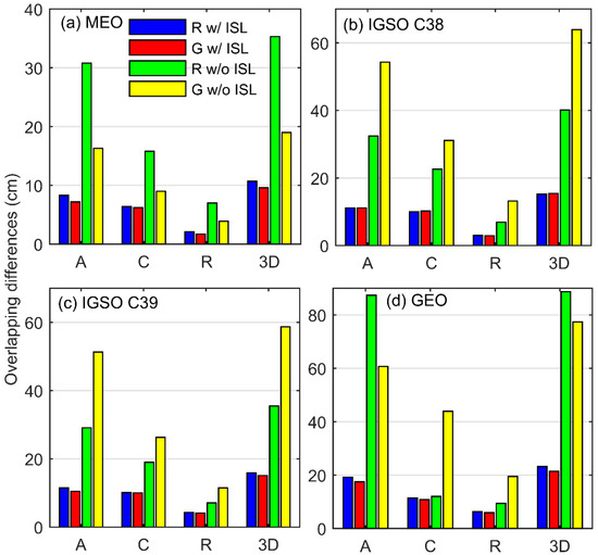
Figure 9.
BDS-3 orbit accuracy obtained by regional (R) or global stations (G) with or without ISL measurements for: MEO satellites (a); IGSO satellite C38 (b); IGSO satellite C39 (c); and GEO satellite C59 (d).
In terms of IGSO satellites, subject to the insufficient number of stations located in the Asia-Pacific region in our selected global tracking network, the orbit accuracy using the 10 regional stations (the green bars) in Figure 9b,c shows better performance than that using the 10 global stations (the yellow bars). Especially in the along-track direction, the RMS of IGSO satellites using the regional stations is 41.8% smaller than that using the global stations. After the addition of ISL data to POD, the accuracy obtained by the two strategies is comparable and the 3D error using regional stations is reduced to 15.2 cm.
The orbit of GEO satellite C59, located at longitude 140°, shows similar performance as IGSO satellites due to the global network selected. For the ground-only POD results, the along-track error generated from 10 regional stations is worse than that generated from 10 global stations. This may be attributed to the fact that the selected regional stations are mainly concentrated in two narrow regions: China in the northern hemisphere and Australia in the southern hemisphere. The GEO satellite fixed above the equator is stationary relative to the ground. In this case, this tracking station distribution is not sensitive to the change of the orbits in the along-track direction. The addition of ISL effectively reduces the along-track error of the regional station POD orbit from 87.4 to 19.3 cm, a significant decrease of 78%. The 3D accuracy is therefore improved by about 73.9%. It follows that ISL can significantly improve the accuracy of the orbits computed with observations from regional stations.
4. Conclusions
The evaluation of the BDS-3 joint orbit determination using the ground-tracking and ISL observations is presented by using an improved joint POD strategy, which is referred to as the Joint 2 POD strategy. This strategy makes full use of the derived ISL geometry-free observables and clock-free observables, thus the performance of computed satellite orbits and clock offsets is improved. The experimental results show that the accuracy of the Joint 2 orbits is higher than ground-only orbits, ISL-only orbits, and Joint 1 POD orbits. For the two joint POD strategies with ISL data, the 3D accuracy of MEO satellites estimated using the Joint 2 strategy is improved by about 9%. In terms of IGSO and GEO satellites, the addition of ISL geometric-free observables increases the errors in the cross-track or along-track direction and results in a slight decrease of 8.5% in the 3D accuracy of the IGSO satellites. However, the results of the independent SLR check and the performance of satellite clock offset estimated with orbit parameters demonstrate that the orbit determination accuracy of the Joint 2 POD strategy is higher than that of Joint 1 POD regardless of the types of orbits.
We also prove that the addition of ISL data can reduce the dependence on the ground stations. The results show that the accuracy of the orbit improves as the number of stations increases. When the number of stations reaches 50, the corresponding orbits achieve similar accuracy as the results using 80 stations. However, as the number of stations is larger than 20, each additional 10 stations contributes to a maximum of 7.5%, 3.9%, and 2.8% improvement for MEO, IGSO, and GEO satellites 3D accuracy, respectively.
Further, the Joint 2 orbits estimated from only 10 regional stations or 10 global stations are analyzed to verify ISL’s enhancement to POD. With the use of ISL measurements, the orbit accuracy of all three types of BDS satellites is greatly improved regardless of the distribution of stations, and the orbits using the global stations are slightly better than those of regional stations with a difference of only 0.9 cm in 3D errors. For the orbits estimated using 10 regional stations, the 3D error of MEO satellites is decreased by 69.7%. In the case of IGSO satellites, the 3D error using regional stations is reduced to 15.2 cm. For GEO satellites, the addition of ISL effectively reduces the along-track error of regional station POD orbits by 78%.
Based on the above analysis, we conclude that the impact of ISL for MEO satellites is rather minor when there are enough ground tracking stations. As for GEO satellites, it is obvious that any improvement of geometry resulting from ISL ranging will have a positive impact on POD. Therefore, an appropriate ground tracking network should be selected for the three types of BDS-3 satellites according to the required accuracy and calculation efficiency.
Author Contributions
Conceptualization, Y.L. and T.G.; methodology, Y.L. and T.G.; software, Y.L.; validation, Y.L. and T.G.; formal analysis, Y.L., T.G. and X.X.; resources, X.W. and F.Z.; writing—original draft preparation, Y.L.; writing—review and editing, T.G. and X.X.; and supervision, Q.Z. All authors have read and agreed to the published version of the manuscript.
Funding
This work was financially supported by the National Natural Science Foundation of China (Nos. 41674004 and 41974036) and Natural Science Foundation of Hubei Province (No. 2019CFA051).
Acknowledgments
International GNSS Monitoring and Assessment System (iGMAS) and IGS Multi-GNSS Experiment (MGEX) are greatly acknowledged for providing BeiDou data.
Conflicts of Interest
The authors declare no conflict of interest.
References
- Yang, Y.; Gao, W.; Guo, S.; Mao, Y.; Yang, Y. Introduction to BeiDou-3 navigation satellite system. Navigation 2019, 66, 7–18. [Google Scholar] [CrossRef]
- Yang, Y.; Mao, Y.; Sun, B. Basic performance and future developments of BeiDou global navigation satellite system. Satell. Navig. 2020, 1, 1. [Google Scholar] [CrossRef]
- China Satellite Navigation Office. BeiDou Navigation Satellite System Signal in Space Interface Control Document Open Service Signal B1C/B2a/B2b/B3I/B1I. Available online: http://en.beidou.gov.cn/SYSTEMS/Officialdocument/ (accessed on 8 March 2020).
- Ananda, M.P.; Bernstein, H.; Feess, W.A.; Paugstat, T.C. Global Positioning System (GPS) Autonomous User System. Navigation 1988, 35, 197–216. [Google Scholar] [CrossRef]
- Ananda, M.P.; Bernstein, H.; Cunningham, K.E.; Feess, W.A.; Stroud, E.G. Global Positioning System (GPS) autonomous navigation. In Proceedings of the IEEE Symposium on Position Location and Navigation. A Decade of Excellence in the Navigation Sciences, Las Vegas, NV, USA, 20 March 1990. [Google Scholar] [CrossRef]
- Rajan, J.A.; Orr, M.; Wang, P. On-Orbit Validation of GPS IIR Autonomous Navigation. In Proceedings of the 59th Annual Meeting of The Institute of Navigation and CIGTF 22nd Guidance Test Symposium, Albuquerque, NM, USA, 23–25 June 2003; pp. 411–419. [Google Scholar]
- Maine, K.P.; Anderson, P.; Langer, J. Crosslinks for the next-generation gps. In Proceedings of the 2003 IEEE Aerospace Conference Proceedings (Cat. No.03TH8652), Big Sky, MT, USA, 8–15 March 2003. [Google Scholar] [CrossRef]
- Menn, M.D.; Bernstein, H. Ephemeris observability issues in the Global Positioning System (GPS) autonomous navigation (AUTONAV). In Proceedings of the 1994 IEEE Position, Location and Navigation Symposium—PLANS’94, Las Vegas, NV, USA, 11–15 April 1994. [Google Scholar] [CrossRef]
- Liu, L.; Zhang, T.; Zhou, S.; Hu, X.; Liu, X. Improved design of control segment in BDS-3. Navigation 2019, 66, 37–47. [Google Scholar] [CrossRef]
- Ren, X.; Yang, Y.; Xu, T.; Zhu, J. Orbit determination of the Next-Generation Beidou satellites with Intersatellite link measurements and a priori orbit constraints. Adv. Space Res. 2017, 60, 2155–2165. [Google Scholar] [CrossRef]
- Yang, D.; Yang, J.; Li, G.; Zhou, Y.; Tang, C. Globalization highlight: Orbit determination using BeiDou inter-satellite ranging measurements. GPS Solut. 2017, 21, 1395–1404. [Google Scholar] [CrossRef]
- Tang, C.; Hu, X.; Zhou, S.; Pan, J.; Liu, L.; Chen, L.; Guo, R.; Zhu, L.; Hu, G.; He, F.; et al. Initial results of centralized autonomous orbit determination of the new-generation BDS satellites with inter-satellite link measurements. J. Geod. 2018, 92, 1155–1169. [Google Scholar] [CrossRef]
- Ren, X.; Yang, Y.; Zhu, J.; Xu, T. Comparing satellite orbit determination by batch processing and extended Kalman filtering using inter-satellite link measurements of the next-generation BeiDou satellites. GPS Solut. 2019, 23, 25. [Google Scholar] [CrossRef]
- Guo, L.; Wang, F.; Gong, X.; Sang, J.; Liu, W.; Zhang, W. Initial results of distributed autonomous orbit determination for Beidou BDS-3 satellites based on inter-satellite link measurements. GPS Solut. 2020, 24, 72. [Google Scholar] [CrossRef]
- Xie, X.; Geng, T.; Zhao, Q.; Cai, H.; Zhang, F.; Wang, X.; Meng, Y. Precise orbit determination for BDS-3 satellites using satellite-ground and inter-satellite link observations. GPS Solut. 2019, 23, 40. [Google Scholar] [CrossRef]
- Yang, Y.; Yang, Y.; Hu, X.; Chen, J.; Guo, R.; Tang, C.; Zhou, S.; Zhao, L.; Xu, J. Inter-Satellite Link Enhanced Orbit Determination for BeiDou-3. J. Navig. 2019, 73, 115–130. [Google Scholar] [CrossRef]
- Ruan, R.; Jia, X.; Feng, L.; Zhu, J.; Huyan, Z.; Li, J.; Wei, Z. Orbit determination and time synchronization for BDS-3 satellites with raw inter-satellite link ranging observations. Satell. Navig. 2020, 1, 8. [Google Scholar] [CrossRef]
- Wang, C.; Zhao, Q.; Guo, J.; Liu, J.; Chen, G. The contribution of intersatellite links to BDS -3 orbit determination: Model refinement and comparisons. Navigation 2019, 66, 71–82. [Google Scholar] [CrossRef]
- Tang, C.; Hu, X.; Zhou, S.; Guo, R.; He, F.; Liu, L.; Zhu, L.; Li, X.; Wu, S.; Zhao, G.; et al. Improvement of orbit determination accuracy for Beidou Navigation Satellite System with Two-way Satellite Time Frequency Transfer. Adv. Space Res. Ser. 2016, 58, 1390–1400. [Google Scholar] [CrossRef]
- Wang, H.; Xie, J.; Zhang, J.; Wang, Z. Performance Analysis and Progress of Inter-satellite-link of Beidou System. In Proceedings of the 30th International Technical Meeting of the Satellite Division of The Institute of Navigation (ION GNSS+ 2017), Portland, OR, USA, 25–29 September 2017; pp. 1178–1185. [Google Scholar]
- Rajan, J.A.; Brodie, P.; Rawicz, H. Modernizing GPS Autonomous Navigation with Anchor Capability. In Proceedings of the 16th International Technical Meeting of the Satellite Division of The Institute of Navigation (ION GPS/GNSS 2003), Portland, OR, USA, 9–12 September2003; pp. 1534–1542. [Google Scholar]
- Saastamoinen, J. Atmospheric Correction for the Troposphere and Stratosphere in Radio Ranging Satellites. Use Artif. Satell. Geod. 1972, 15, 247–251. [Google Scholar]
- Boehm, J.; Niell, A.; Tregoning, P.; Schuh, H. Global Mapping Function (GMF): A new empirical mapping function based on numerical weather model data. Geophys. Res. Lett. 2006, 33, 7. [Google Scholar] [CrossRef]
- Wu, J.T.; Wu, S.C.; Hajj, G.A.; Bertiger, W.I. Effects of antenna orientation on GPS carrier phase. Astrodynamics 1992, 18, 1647–1660. [Google Scholar]
- Petit, G.; Luzum, B. IERS conventions (2010) (No. IERS-TN-36). In Proceedings of the International Earth Rotation and Reference Systems Service (IERS), Meudon, France, 17–19 September 2010. [Google Scholar]
- Förste, C.; Schmidt, R.; Stubenvoll, R.; Flechtner, F.; Meyer, U.; König, R.; Neumayer, H.; Biancale, R.; Lemoine, J.; Bruinsma, S.; et al. The GeoForschungsZentrum Potsdam/Groupe de Recherche de Gèodésie Spatiale satellite-only and combined gravity field models: EIGEN-GL04S1 and EIGEN-GL04C. J. Geod. 2008, 82, 331–346. [Google Scholar] [CrossRef]
- Springer, T.A.; Rothacher, M.; Beutler, G. A New Solar Radiation Pressure Model for GPS Satellites. GPS Solut. 1999, 2, 50–62. [Google Scholar] [CrossRef]
- Guo, J.; Xu, X.; Zhao, Q.; Liu, J. Precise orbit determination for quad-constellation satellites at Wuhan University: Strategy, result validation, and comparison. J. Geod. 2015, 90, 143–159. [Google Scholar] [CrossRef]
- Pearlman, M.R.; Degnan, J.J.; Bosworth, J.M. The International Laser Ranging Service. Adv. Space Res. 2002, 30, 135–143. [Google Scholar] [CrossRef]
- Pearlman, M.R.; Noll, C.E.; Pavlis, E.C.; Lemoine, F.G.; Combrink, L.; Degnan, J.J.; Kirchner, G.; Schreiber, U. The ILRS: Approaching 20 years and planning for the future. J. Geod. 2019, 93, 2161–2180. [Google Scholar] [CrossRef]
- Zhao, Q.; Wang, C.; Guo, J.; Wang, B.; Liu, J. Precise orbit and clock determination for BeiDou-3 experimental satellites with yaw attitude analysis. GPS Solut. 2017, 22, 367. [Google Scholar] [CrossRef]
- Zhu, L.; Pan, J.; Shuai, T.; Tang, C.; Xie, Y.; Liu, L.; Hu, X.; Chang, Z.; Zhou, S.; Wu, Z. Performance of the BDS3 experimental satellite passive hydrogen maser. GPS Solut. 2018, 22, 647. [Google Scholar] [CrossRef]
- Zhang, Q.; Moore, P.; Hanley, J.; Martin, S. Auto-BAHN: Software for near real-time GPS orbit and clock computations. Adv. Space Res. 2007, 39, 1531–1538. [Google Scholar] [CrossRef]
© 2020 by the authors. Licensee MDPI, Basel, Switzerland. This article is an open access article distributed under the terms and conditions of the Creative Commons Attribution (CC BY) license (http://creativecommons.org/licenses/by/4.0/).