Abstract
Synthetic Aperture Radar (SAR) is an established remote sensing technique that can robustly provide high-resolution imagery of the Earth’s surface. However, current space-borne SAR systems are limited, as a matter of principle, in achieving high azimuth resolution and a large swath width at the same time. Digital beamforming (DBF) has been identified as a key technology for resolving this limitation and provides various other advantages, such as an improved signal-to-noise ratio (SNR) or the adaptive suppression of radio interference (RFI). Airborne SAR sensors with digital beamforming capabilities are essential tools to research and validate this important technology for later implementation on a satellite. Currently, the Microwaves and Radar Institute of the German Aerospace Center (DLR) is developing a new advanced high-resolution airborne SAR system with digital beamforming capabilities, the so-called DBFSAR, which is planned to supplement its operational F-SAR system in near future. It is operating at X-band and features 12 simultaneous receive and 4 sequential transmit channels with 1.8 GHz bandwidth each, flexible DBF antenna setups and is equipped with a high-precision navigation and positioning unit. This paper aims to present the DBFSAR sensor development, including its radar front-end, its digital back-end, the foreseen DBF antenna configuration and the intended calibration strategy. To analyse the status, performance, and calibration quality of the DBFSAR system, this paper also includes some first in-flight results in interferometric and multi-channel marine configurations. They demonstrate the excellent performance of the DBFSAR system during its first flight campaigns.
1. Introduction
Synthetic Aperture Radar has evolved in a well-established remote sensing technique that can robustly provide high-resolution imagery of the Earth’s surface independent of weather and daylight conditions. SAR images of the Earth are now acquired on a regular basis by an increasing number of satellites and form the basis for a wide range of remote sensing applications and services. While the performance of spaceborne SAR systems has significantly evolved over the past decades, their imaging capabilities are still rather limited: conventional SAR is not capable of obtaining both a high resolution and a wide swath at the same time due to principal constraints in the sampling conditions and antenna size [1]. To overcome this fundamental limitation, the past few years have seen intense research activities towards new SAR system designs and architectures that employ not only one, as in conventional SAR, but multiple digital receive channels. These multi-channel instrument architectures mark a paradigm shift in the design of SAR systems, enabling new so-called digital beamforming imaging modes. Digital beamforming for transmit and/or receive will solve the contradiction posed by the antenna size in traditional SAR systems that prohibits the SAR sensor from having high azimuth resolution and a large swath width at the same time [2].
Apart from high coverage with enhanced spatial resolution, digital beamforming modes also promise viable solutions for a couple of other limitations in SAR. For example, it is possible to significantly enhance the SNR through adaptive control of transmit and receive beams. In addition, susceptibility to RFI can be reduced by adaptive nulling of the receive directions in which external radio sources have been detected [3,4]. With DBF, it becomes possible to simultaneously image in several conventional SAR modes by fully controlling the antenna beams offline after raw data acquisition, which is particularly important for future bi- and multi-static satellite constellations [5]. Finally, an already well-known and established capability of multi-channel SAR receivers is the possibility of moving target indication (MTI), where multiple antennas in azimuth are used to detect and measure moving objects [6]. Summarizing, digital beamforming can be seen as an upcoming key technology for future SAR systems, allowing a significantly enhanced imaging flexibility and performance. In this way, digital beamforming will enable new imaging modes and open new fields of applications [7].
Airborne SAR sensors with digital beamforming capabilities allow to research the key aspects of digital beamforming and to establish the necessary technology for later implementation on satellites. Up to now, only few of such airborne DBF SAR systems have been established. One example is NASA’s (National Aeronautics and Space Administration) Digital Beamforming Synthetic Aperture Radar aka DBSAR, a very flexible multi-mode L-band system with electronic beamforming on transmit and 8-channel digital beamforming on receive [8]. With the introduction of its successor DBSAR-2, it has been recently been upgraded to 16 channels and higher spatial resolution [9]. SweepSAR is another airborne digital beamforming SAR demonstrator of NASA [10]. It is a reflector-based 16-channel Ka-band system foreseen to simulate L-band spaceborne scenarios, such as NISAR [11] and Tandem-L [12], with a main focus on ice and solid earth topography. It is also worth noting the development of an airborne Ka-band Digital Beamforming SAR System with 24 channels at the Chinese Academy of Sciences, which employs real-time DBF focusing in elevation to achieve an enhanced MTI performance [13].
The Microwaves and Radar Institute of the German Aerospace Center (DLR) has been developing and operating state-of-the-art airborne SAR sensors for several decades. The current operational system, the F-SAR, is an advanced multi-frequency polarimetric and interferometric sensor system [14]. It features, however, only a maximum of two simultaneous receive channels for each frequency band and thus cannot be used for digital beamforming operation. Triggered by the urgent need for an airborne sensor with DBF capabilities to support technology research for future space-borne SAR systems, together with an increasing demand for very high-resolution SAR imagery, the development of an advanced 12-channel X-band DBF extension, the so-called DBFSAR, has been conducted at DLR. The system’s maiden flight was successfully completed in autumn 2016, followed by several further trials in various configurations the years after.
In the following section, the instrument design and sensor hardware of the new DBFSAR sensor is presented in detail, including the X-band radar front-end, the high-performance digital back-end, the navigation unit, and the foreseen flexible DBF antenna configuration. The inter-channel calibration concept of DBFSAR, which is an important topic in every DBF systems, is outlined in Section 3, including the precise correction of pointing and baseline inaccuracies in the antenna array. Finally, Section 4 presents results obtained during some first in-flight trials with the DBFSAR, which were conducted to evaluate and optimise the system performance and calibration strategy.
2. DBFSAR Instrument Design
The basic concept of the DBFSAR radar system follows the flight and campaign proven setup of the former F-SAR system layout [14,15]. The hardware is divided into different units, depending on the task to fulfill. There are two main racks, which build the core setup called the digital and navigation unit. These core units are designed in a way that a modular combination of different radar racks for specified frequency bands is possible. The first realized radar unit is operating in the X-band at a center frequency of 9.5 GHz with a total system bandwidth of 1.8 GHz.
In summary, the DBFSAR system comprises of four main components (see also Figure 1):
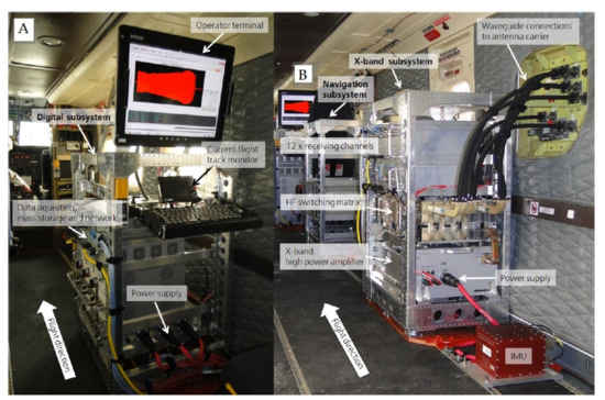
Figure 1.
(A) DBFSAR mounted in the cabin of DLR’s Do228 aircraft: digital backend in the back, (B) HF front-end in the front and X-band wave-guide connections on the very right of the image.
- Digital subsystem: The digital backend includes the data acquisition to sample and record 12 receive channels with 2 GHz bandwidth individual, as well as the complete system control and a user console for the flight operator.
- Navigation subsystem: The navigation rack provides the mission in-flight pattern for the pilot and records the GPS (global positioning system) position and the IMU (inertial measurement unit) data for real-time on-board or post processing. Additionally, an AIS (automatic identification system) receiver and a LTE (long-term evolution) modem for data transmission are implemented.
- X-band subsystem: The front-end contains all HF (high-frequency) components, including the X-band high power amplifier. It features 12 simultaneous receive and 4 sequential transmit channels with 1.8 GHz analogue bandwidth each.
- DBF antennas: The antenna configuration consists of a dedicated antenna carrier, carrying 4 single-pol X-band transmit antennas, aligned in H and V direction forming wide or narrow beams, and 12 receive antennas, which can be arranged in various configurations. Alternatively, a dedicated MTI antenna system, the V-SAR antenna, can be mounted.
2.1. The Digital Subsystem
In the digital rack, all components for the central system control and in-flight operations are integrated. This includes the radar display, the navigation display, the console, and the components for 12-channel data acquisition and on-board real-time processing. System control and data acquisition units are designed in a way that they can drive both the new digital-beamforming X-band subsystem of DBFSAR using Ethernet, and the existing older F-SAR HF racks using CAN (Controller Area Network) bus. The entire radar can be operated by a single person. The data acquisition unit (DR2 in Figure 2) possesses 12 analog-digital converters (ADC) with 4 GS/s and 8 bits and integrated field-programmable gate array (FPGA) for real-time data pre-processing. The radar raw data are recorded with a maximum of 3 GB/s on 12 solid state drives, which can be accessed over a 10 Gb Ethernet interface for data transfer. For real-time processing, the data stream of all ADC can be connected to three high-performance CPUs. The timing unit (DR3 in Figure 2) is used for generation of the reference frequencies (DBFSAR: 100 MHz, F-SAR: 50 MHz), clock and trigger for radar synchronization as well as for generation of the time stamps for the co-registration of navigation and raw data. The clock for the ADC and all triggers are derived from a high-precision 100 MHz reference. For generation of the time stamps, GPS time and 1 PPS pulse are fed in from the navigation system. The radar control unit (DR5 in Figure 2) is responsible for driving and monitoring the radar operations. It includes a 20 flight-certified display and rugged keyboard. The control computer uses Linux as operating system and runs either a new DBFSAR control software, or an adapted version of the F-SAR control software. On its 10 Gb Ethernet interface, an additional GPU module is foreseen for enhanced real-time processing.
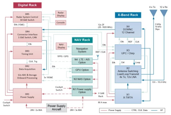
Figure 2.
Block diagram of DBFSAR’s digital and X-band subsystems.
2.2. The Navigation Subsystem
The navigation subsystem provides the mission flight track information for the pilot and the radar operator. The track information is displayed at the mission monitor in the cockpit and at the radar operator terminal as well. The radar operator can select the flight tracks so the pilot can fully concentrate on the flight trajectory. The accuracy when following the flight path is after a post processing in the range of a few centimeters [16]. The flown flight trajectory is recorded by two independent GPS receivers with the combination of an IMU to record the airplane orientation, which is important to post calculate the antenna phase centers. Additionally, an AIS receiver for ship detection is installed (N4 in Figure 2). This enables the possibility of refocusing SAR images by the correction of the Doppler shift caused by ship motion (see initial AIS evaluations in [17] and in detail in Section 4.3). A LTE mobile network modem is used for real-time data transfer (N4 in Figure 2). A first test flight showed a maximum data rate of 10 Mbit/s. For the first setup, the LTE antennas have been placed right behind the windows inside the cabin to avoid costly aircraft certification efforts. This is of course not ideal and leads to data link errors during flight maneuvers. A higher data link stability and an increased data rate will be achieved in future by changing the position of the LTE antennas to the lower side of the wings or fuselage.
2.3. The X-Band Subsystem
In the X-band front-end, transmitter, signal generation and the 12-channel receiver of the radar are integrated. The transmit/receiver frequency range lies between 8.6 and 10.4 GHz, and the pulse modulation is freely programmable. The X-band subsystem is controlled in real-time via Ethernet to set the transmit and receive triggers and to be synchronized with the system clock. All oscillators are strictly linked to the 100 MHz system reference. The trigger and system references are generated in the digital subsystem. The X-band subsystem can be connected to 12 receive and 4 transmit antennas, where the former are operated simultaneously and the latter sequentially.
As high-power amplifier (X1 in Figure 2), an air-cooled wide-band travelling wave tube (TWT) is used, allowing for transmit powers of around 2 kW peak with a maximum duty cycle of 10%. The antenna switching matrix (X2 in Figure 2) is a high-power transmit matrix in waveguide technology with 12 integrated low-noise amplifiers (LNA) and frequency range filter on receive side. The transmit power can be switched to either the transmit ports or onto a dummy load. Over a coupler, fast switches, and a power divider, each LNA input can be connected to a calibration signal. The signal generator (X3 in Figure 2) contains a chirp generator with up-conversion and a control- and reference signal distribution. The chirp generator is an arbitrary waveform generator (AWG), which is capable of generating transmit signals of up to 1.8 GHz bandwidth. The waveform is freely programmable up to a maximum duration of 250 ms. It is possible to register up to 15 waveforms, which can be transmitted either sequentially or stitched together as a single waveform. It is also possible to generate frequency modulated continuous wave (FMCW) signals. The 12-channel down converter (X4 in Figure 2) features an input frequency range of 8.6–10.4 GHz and converts with a single-sideband downconverter to the range of 20–1820 MHz. With the integrated actuators, the receive gain can be varied temporally synchronized within a dynamic range of 63 dB from pulse to pulse or even within a pulse. The conversion frequency and phase can be freely programmed through the oscillator. Possibilities for step-frequency operation and usage of external oscillators are also implemented.
A summary of DBFSAR’s system parameters can be found in Table 1.

Table 1.
DBFSAR X-Band radar system parameters.
2.4. DBF Antenna Configurations
The DBFSAR system design foresees two different antenna configurations: one very flexible 12-channel DBFSAR antenna to conduct various kinds of DBF experiments in both along- and across-track settings, and a dedicated 6-channel MTI antenna system. In the following, the former is referred to as DBFSAR antenna, while the latter is referred to as V-SAR antenna. At a time, only one of the two antennas can be integrated into the antenna carrier mounted to the exterior of the airborne platform, i.e., they cannot be used both during the same acquisition flight. The antennas are connected to the X-band subsystem via a set of WR90 waveguides.
The DBFSAR antenna system consists of 4 individual single polarized transmit horn antennas, which are designed for high average power, and 12 DBF receive antennas, based on microstrip technology. Important general design parameters are 2 GHz system bandwidth at 9.5 GHz center frequency. The transmit antennas have equal pattern characteristics in the two principal planes, thus the antennas can be used either to transmit horizontally or vertically polarized signals, dependent on the orientation of the antenna in the antenna frame. With a set of two antennas a full polarimetric measurement is possible. The antenna frame supports four transmit antennas, one pair with 30 half power beamwidth and an alternative pair with narrow beamwidth of 16. On the receive side, DBF modules consisting of 1 × 4 stacked patch elements are used, denoted as DBFRAM (DBF Receive Antenna Modules). A photo of such a DBFRAM module is shown in Figure 3b. The subarrays possess a high efficiency (>75%) and constant amplitude and phase distribution for minimizing noise figures. A maximum of 12 of these DBFRAM modules are combined to form the actual DBF receive array needed, allowing for pointing angles up to ±15 deg, in respect to the maximum illuminated footprint of the transmit antennas. A reconfigurable antenna backplane allows various combinations of DBFRAM modules, in along-track directions, across-track directions, or a mixture of both (Figure 3a). If needed, two of the DBFRAM modules can be combined in a second level to form alternative 1 × 8 or 2 × 4 subarrays, to be then combined into the full DBF array. The antenna backplane is designed to house the DBFRAM module in both vertical and in horizontal orientation.
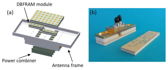
Figure 3.
(a) Schematic representation of the DBFSAR antenna backplane, constructed to realize various DBF configurations out of a large number of DBFRAM modules; and (b) single DBFRAM module, containing a 1 × 4 patch.
For MTI applications and situation monitoring, a particular multi-channel, multi-antenna setup has been designed. The so-called V-SAR antenna houses one dedicated single-pol transmit antenna, six independent single-pol receive antennas, and a dual polarized imaging antenna (see Figure 4). All antennas are equipped with DBFRAM modules, as described above; the entire antenna consists of 80 such DBFRAM modules. The concept of the DBF antenna box is transferred to the V-SAR antenna by the use for DBFRAM subarrays and additional feeding networks in a second level behind the radiating modules. Small SMP connectors allow a plug-in solution to connect the individual network layers without screwing. Each receive channel consists of a 3 × 2 DBFRAM module configuration, connected via a single network layer. The dual-polarized imaging antenna is formed by 4 × 3 elements with a multilayer board of 12 copper layers to combine the modules and form a sufficient azimuth pattern. The elevation pattern is generated by an additional elevation beam forming network (Figure 4).
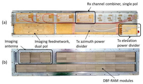
Figure 4.
(a) Partially assembled V-SAR antenna with multiple RX channels and two individual transmit antenna configurations. View into the feeding network structures; and (b) view to the front part of the V-SAR multi-channel antenna without radome, consisting of 80 DBFRAM modules.
To mount the antennas to the body of an aircraft in an optimal way, a dedicated antenna carrier is needed. Such a carrier for DLR’s Do228-212 research aircraft has been designed and is currently under construction. A screenshot of the CAD model on the airplane is shown in Figure 5. The carrier will be placed in the lower middle part of the aircraft’s body at the right side (starboard) and will support the antennas with about 45 mechanical steering in elevation. This configuration guarantees a minimum of multi-pass effects and electromagnetic interference with the body of the airplane and optimizes illumination in the important range of 30–60 incident angles.
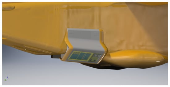
Figure 5.
Schematic view of the DBFSAR antenna carrier mounted on the side of the aircraft body. The antenna carrier is currently under construction.
The DBFSAR antenna carrier is currently not yet available. For the first flight tests of the radar system, as described in the next sections, the existing F-SAR antenna carrier had to be used [15]. It can carry up to three of the dual-pol F-SAR antennas in an across-track (XTI) and along track (ATI) interferometric setup, thus limiting the operation to non-DBF modes and bandwidth to 800 MHz maximum. Additionally, an adaption of the V-SAR antenna has been done to be able to integrate and use it also in this antenna carrier.
3. Multi-Channel Sensor Calibration
As a next generation, multi-channel SAR sensor, DBFSAR supports numerous innovative imaging modes including single-pass polarimetric multi-baseline interferometry, multi-channel along-track interferometry, and, of course, a wide range of possibilities leveraging digital beamforming. All of these applications rely on highly accurate sensor calibration to ensure inter-channel consistency in terms of amplitude, delay, and phase. This is especially critical in the context of digital beamforming: systematic calibration issues at the level of individual channels will impair or even prohibit image formation itself, as the effective antenna illumination patterns will deviate from the expectation.
To meet these stringent requirements in terms of sensor calibration accuracy, an entirely new, model-based approach based on the analysis of range compressed raw data has been developed [18]. Besides the usual scalar calibration corrections in terms of channel gain, channel delay, and channel phase, the new approach facilitates the robust estimation and correction of propagation direction dependent calibration issues. These include 3D antenna phase center and baseline corrections and 3D antenna pointing corrections. The fact that this calibration approach does not require SAR image focusing in azimuth is also relevant in the context of DBF, where individual channels need to be calibrated but may, by themselves, under-sampled.
Figure 6 illustrates the impact of multi-channel baseline calibration upon the inter-channel phase consistency. The plots show residual phase differences measured along the range histories of several trihedral radar reflectors in a single X-band acquisition of the V-SAR sensor. The left column of the figure represents the input to the calibration process, where the assumed antenna phase center positions are those obtained from on-ground characterization of the antenna array. The target responses indicate that the inter-channel phase difference varies significantly as a function of the propagation direction and from baseline to baseline. Such propagation direction dependent inter-channel phase inconsistencies are effectively compensated for by the introduction of calibration refinements to the nominal antenna phase center positions: phase center position calibration leads to baseline changes and a removal of systematic phase deviations, as shown in the right column of the figure.
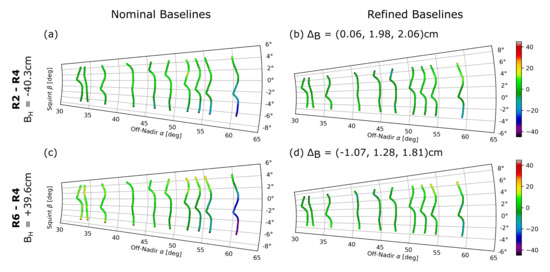
Figure 6.
A comparison of residual interferometric phase errors before and after 3D baseline calibration for two different channel combinations. Each colored line represents the range history of a single trihedral reflector in the polar antenna coordinate system. Colors indicate the phase errors measured along the phase history. The columns separate the phase error evaluation before (a,c) and after (b,d) baseline calibration. The horizontal baseline is annotated on the left side of each row, while the right column includes the 3D baseline correction estimated in the calibration process.The first row (a,b) represents a pair of channels with receive antennas 2 and 4, while the second row (c,d) corresponds to receive antennas 6 and 4.
The impact of the baseline calibration corrections introduced is further illustrated in Figure 7, which shows the interferometric phase differences measured over distributed targets in the calibration site. A comparison of the interferometric measurements before and after baseline calibration shows that calibration successfully removes systematic phase trends and ultimately leads to phase differences close to zero, as is expected for along-track baselines and a largely static scene. It should be noted that calibration also appears to have removed higher-frequency phase undulations in the range direction. This effect is not, in fact, due to baseline calibration. Instead, it is related to the antenna pointing calibration. After the 3D pointing correction is introduced by the calibration approach, the antenna pattern phase can be corrected more accurately and phase undulations disappear from the interferograms.
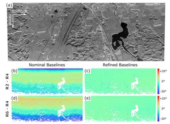
Figure 7.
The impact of baseline calibration on the along-track interferometric phase measured in an acquisition of the V-SAR sensor over the calibration test site in Kaufbeuren, Germany: (a) the backscatter amplitude at X-ban; and (b–e) a matrix showing the along-track interferometric phase before and after baseline calibration (columns) for two of the five baselines (rows). The interferometric channel combinations shown as well as the 3D baseline corrections in (b–e) correspond to those of Figure 6a–d, respectively.
Finally, Figure 8 aims to show that the results of multi-channel sensor calibration also transfer to data gathered in the field. The example dataset is a scene acquired, in a different part of Germany, in the days following the calibration data take of Figure 7. The interferograms for the three along-track baselines show no obvious trends or phase offsets. Indeed, the phase histograms over stationary parts of the scene (green polygon) suggest an absolute phase accuracy within a few degrees. Phase differences over the water, meanwhile, indicate movement in opposing directions due to surface waves and/or currents (blue and orange polygons). As expected, the sign and magnitude of the phase is proportional to the along-track baseline, as well as the radial surface velocity. The high degree of transferability of calibration information suggested by these results is evidence of the stability of the radar instrument, the fidelity of the internal calibration signals it provides, and can also be considered a validation of the models underlying the calibration approach developed.
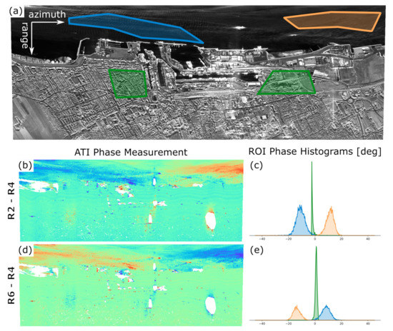
Figure 8.
Along-track interferometric phase measurements of the V-SAR sensor over the city of Cuxhaven on the North Sea coast in Germany: (a) the backscatter amplitude at X-band, as measured in one of the six simultaneously acquired VV-pol channels, where polygons indicate regions of interest (ROIs) used for further detailed analysis; and (b–e) a matrix showing the along-track interferometric phase (b,d) and ROI phase histograms (c,e) for two of the five baselines. The baselines correspond to those shown in Figure 6 and Figure 7.
4. Test Flights and Experimental Results
4.1. First Imaging Results
The maiden flight of the DBFSAR system took place on 29 November 2016 over the calibration test site Kaufbeuren in southern Germany. This test site is permanently equipped with an array of trihedral corner reflectors for calibration purposes. As mentioned above, the dedicated DBFSAR antenna carrier is not yet available. Therefore, for all flight tests, the existing F-SAR antenna carrier together with the older F-SAR antennas were used. This implied a number of limitations with respect to the full potential of the DBFSAR sensor:
- Only two F-SAR antennas have been mounted in an interferometric XTI configuration. Consequently, no DBF modes have been tested yet. However, both antennas are dual-pol, so that simultaneous receive on four channels could be demonstrated.
- The F-SAR X-band antennas are not designed for DBFSAR’s 1.8 GHz bandwidth. For this experiment, it was decided to limit the bandwidth to the 800 MHz, which fits well to the operation capability of the F-SAR antennas.
The first flights were completed very successfully and raw data in various modes were collected and processed. Figure 9a shows an image of the full swath of about 3 km. This dataset is fully calibrated and was processed with a resolution of 19 cm × 10 cm in range/azimuth. Figure 9b shows a zoom into the area, containing a trihedral corner reflector in the left and several strong target echoes in the right of the image. No spectral weighting has been applied in this case to reach maximum resolution. It has to be noted that these image results have been reached without using any auto-focusing techniques; motion compensation solely relies on navigation data provided by the GPS/IMU system of the aircraft. Figure 10a,b depicts the achieved spatial resolution, measured over a set of trihedral corner reflectors placed under different elevation angles. The data were processed to an azimuth resolution of 10 cm, the theoretical range resolution corresponding to 800 MHz bandwidth is 18.75 cm. While the achieved azimuth resolution almost matches the theoretical one, the achieved range resolution is slightly too high. This can be explained by the spectral expansion in range occurring due to line-of-sight variations during the very long synthetic aperture.
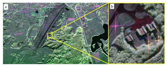
Figure 9.
First fully calibrated DBFSAR image, showing the calibration test site of Kaufbeuren (a), including a zoom into the small feature marked in yellow to illustrate the high resolution imaging capabilities of DBFSAR. HH = blue, VV = red, and HV = green (b).
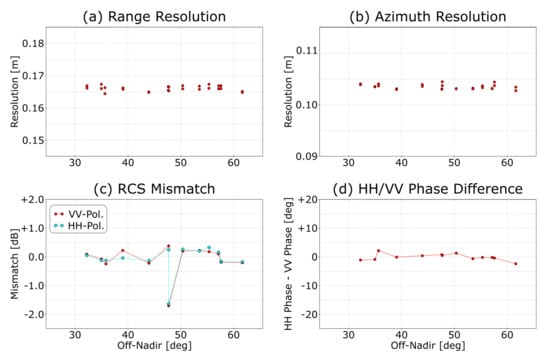
Figure 10.
Results of analyzing the response of trihedral reflectors deployed at regular intervals across the imaged swath in focused SAR imagery of the 16DBFTST campaign. Clockwise from the top left: the range (a) and azimuth (b) resolution achieved; the difference between the expected and the measured target radar cross section (c); and HH/VV polarimetric phase imbalance (d).
Figure 10c,d shows an analysis of the radar cross section (RCS) errors and the co-polar phase error. Both are very low, demonstrating an excellent relative phase and amplitude calibration of the system with a standard deviation of about 0.3 dB for the amplitude and about 1 for the phase. Only at 48 a large deviation in RCS is present, which is presumably due to snow and/or ice in the respective trihedral reflector.
4.2. First Interferometric Results
The second set of test flights was conducted end of March 2017 and encompassed the simultaneous recording on six data receivers which were connected to the polarimetric antennas of the across-track and along-track X-band interferometers on the F-SAR antenna mount. The system was programmed to record in an alternate way in full-baseline (by toggling the transmit antenna) and half-baseline (with common transmit antenna) modes in all polarizations, equivalent to a dual-baseline Pol-InSAR mode. In parallel, the half-baseline mode of the along-track interferometer was operated, resulting in a pulse sequence length of 4, which was repeated periodically. Table 2 presents the programmed sequence in a tabular way, showing:
Table 2.
Pulse sequence for the simultaneous dual-baseline Pol-InSAR XTI and half-baseline ATI mode: active antennas and operation sequence for the 2017 interferometry tests.
- the across-track channels’ operation for the XTI Pol-InSAR mode on antennas X1 and X2, which makes use of all four Tx-pulses of the sequence; and
- the along-track channels’ operation for the ATI mode on antennas X2 and X3, which involves Pulses 2 and 4 only.
Five fully polarimetric images can thus be processed, namely X11, X12, X21, X22, and X23, where the numbers represent the used antenna ID for transmit and receive, respectively. Note that each independent antenna/polarization channel was recorded with a constant PRF of 1/4 of the system PRF of 4.6 kHz in this case.
Figure 11 shows the polarimetric imaging result of X11, as well as the X11–X12 and X11–X22 interferometric coherences and residual phases for a scene collected in the vicinity of the Lake of Starnberg in Southern Bavaria, Germany. Due to antenna limitations, the transmit bandwidth was again restricted to 800 MHz. The SRTM digital elevation model (DEM) was used for phase flattening. The imaging result shows excellent quality in terms of SNR and calibration performance. The shown scene of size 2 km by 11.5 km was flown from east to west, with near range on top from left to right. The overall data acquisition is 60 km long, demonstrating the recording capacity of the new DBFSAR sensor. The polarimetric image allows already visual interpretation of different land use classes. However, polarimetry-based segmentation and clustering schemes could be applied for automatic classification purposes [19]. Additional information comes from the interferometric channels, which, apart from DEM, provide measurements of different levels of volume decorrelation, e.g., in forested areas, and which allow deriving vegetation maps and height and/or biomass estimates either by means of the Pol-InSAR approach [20] or using just a single-polarization single- or multi-baseline approach, as experimented with TanDEM-X data [21,22]. As the DBFSAR system records all channels and polarizations simultaneously, the data are not affected by any temporal decorrelation and can serve as a perfect reference.
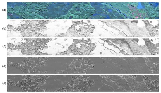
Figure 11.
(a) X-band polarimetric SAR image in Pauli basis with Tx and Rx on X1 antenna; (b,c) coherence of HH polarization in full-baseline and half-baseline mode; and (d,e) residual phase in full-baseline and half-baseline mode.
4.3. First Ship Detection and Tracking Results Obtained with the V-SAR Subsystem
The dominating systems used nowadays for maritime traffic situation awareness are AIS [23], marine radars onboard the ships, and ground-based radars on the coast. Additionally, high-flying radar sensors are expected to complete the maritime situation picture [24,25], for instance, by detecting ships not recognizable with coastal radars and/or not equipped with AIS transponders. The V-SAR subsystem with its multi-channel antenna (Figure 4) is well suited to investigate and demonstrate new methods and applications in the field of maritime security. For this task, in November 2019, a multi-channel flight campaign in V-SAR configuration was carried out in the North Sea near Cuxhaven, Germany. This time the onboard dual-channel AIS receiver was integrated (navigation rack block diagram in Figure 2) and enabled. In a flight altitude of 2400 m above sea level, AIS signals from ships with distances up to 200 km away from the aircraft were received. Figure 12 shows the AIS receiver mount (left) and AIS position messages received during a 70 s period (right).
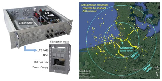
Figure 12.
Onboard AIS dual-channel receiver and LTE router for data transfer to ground (left) and AIS signals received during a flight campaign conducted in the North Sea around Cuxhaven in November 2019 (right). During a single flight track with a radar acquisition of 70 s duration a number of 1497 AIS position messages (yellow dots) was received from ships with distances up to 200 km far away.
For future maritime security applications, an automatic processing framework has been developed, which operates on range-compressed data. This framework is composed of processing data blocks for ship detection, tracking, geocoding, inverse SAR (ISAR) imaging, and AIS data fusion. In Figure 13, some results achieved with data from the North Sea flight campaign are shown.
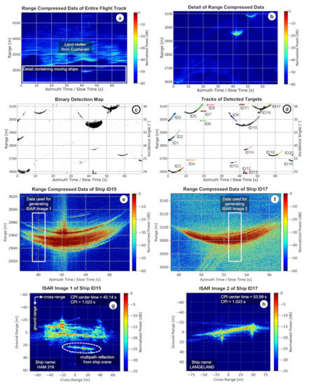
Figure 13.
Preliminary ship detection, tracking and ISAR imaging result obtained from V-SAR airborne radar data. In the images, the following are shown: (a) range-compressed radar data acquired during a single linear flight track (the corresponding fully focused SAR image is shown in Figure 8 at the top); (b) crop of the data containing several ship signals but no land clutter; (c) binary detection map obtained after applying a CFAR detector; (d) ship tracking results obtained by a tracker based on the Kalman filter; (e,f) range-compressed data belonging to the tracked ships with IDs 15 and 17; and (g,h) corresponding ISAR images obtained by a generic ISAR processor—the used CPI of 1.023 s results in a cross-range resolution of approximately 0.6 m.
In Figure 13a, single-channel range-compressed data acquired during one flight track are shown. These data contain land clutter from the town Cuxhaven as well as some ship signals. A crop of the region marked with the white box is depicted in Figure 13b. Two very strong ship signals can clearly be recognized in the upper right. However, in total, there are more than just two ship signals contained in the data, as revealed by the binary detection map depicted in Figure 13c. These detections are obtained by a constant false alarm rate (CFAR) detector. The CFAR detection thresholds are computed adaptively by taking into account the surrounding ocean clutter statistics which vary over time and location. Details about the used CFAR detector are given in [26].
In Figure 13d, the tracking results obtained from a tracker based on the Kalman filter [27] are shown. In total, 21 target tracks were initiated with track durations of up to 10 s and more. Since the employed processing framework also includes track management, ghost tracks caused by false detections can be recognized and terminated after a few seconds. For instance, the tracks with IDs 1, 4, 6, 7, 8, and 11 are obviously ghost tracks terminated after 3–5 s. The tracking information is used for extracting and separating the range-compressed data belonging to each tracked ship. This is shown in Figure 13e,f for the ship tracks with IDs 15 and 17. By using the extracted range-compressed data and slicing them into smaller blocks with an azimuth duration corresponding to the coherent processing interval (CPI), an ISAR image sequence can be generated. For ISAR imaging, we use the generic ISAR processor discussed in [28,29]. In Figure 13g,h, the ISAR images obtained from the range-compressed data marked with the white boxes in Figure 13e,f are shown. Figure 13g shows the ship HAM 316, which is a dredger of dimensions 129 m × 22 m [30]. This ship contains several cranes and booms on the deck, one of them causes a strong multipath reflection clearly recognizable in the ISAR image. The ship in Figure 13h is the cargo ship LANGELAND with dimensions 82 m × 12 m [31]. Two masts in the front and back of the ship can clearly be recognized.
In conventionally processed SAR images, moving objects appear displaced from their actual position, caused by an additional Doppler shift due to the line-of-sight velocity of the object [32]. However, a multi-channel system with a certain along-track baseline between the antennas allows computing the direction-of-arrival (DOA) angle of the signal and, therefore, to precisely estimate the geographical coordinates of a target [33,34]. In this study, a DOA estimator based on the maximum-likelihood principle was used [35,36]. Thus far, only four out of six receiving antennas of V-SAR have been used and no clutter suppression was carried out. The results for the ships HAM 316 and LANGELAND are shown in Figure 14 in orange color, together with the received AIS position messages (white color). It can be seen that the differences between the geocoded radar detections and the AIS positions in most cases are below 30 m. This indicates that the estimated DOA is very accurate. The next steps are a more sophisticated position accuracy evaluation, taking into account more data channels and longer ship tracks.
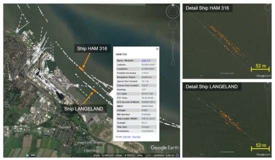
Figure 14.
Geocoded radar-based detections of the ships HAM 316 and LANGELAND (orange) and received AIS position messages (white) visualized with Google Earth. Test site: Cuxhaven, Germany.
5. Discussion
The newly developed DBFSAR system has successfully conducted its maiden flight and showed an excellent performance during its first data takes, including first trials in interferometric and marine MTI configurations. The innovative calibration strategy, a crucial step in every multi-channel SAR system, has been found to work well and to deliver high-quality data. However, the system has not yet been evaluated using its maximum system bandwidth of 1.8ĠHz. It remains a challenge to maintain a precise inter-channel phase calibration when processing different DBF modes with very high bandwidth. In addition, the influence of thermal dilatation and vibrations on the DBF performance still needs to be investigated.
The main limitation of the current system is that the final DBF antenna is not yet available. Experiments are currently thus limited to use either the V-SAR antenna (MTI configuration) or the old F-SAR antennas with reduced bandwidth and only in interferometric configuration. Full-fledged DBF experiments will become possible when the new antenna becomes ready, which will allow a high flexibility in DBF configurations in both along- and across-track directions. For large interferometric baselines, the existing F-SAR antenna setup will remain available as an alternative. Up to now, a gimbaled antenna system for improved motion compensation has not been implemented, but is considered as an option for a future system upgrade.
Generally, the system control and signal generation of DBFSAR is very flexible and allows the realization of a multitude of signal types and sequences, for example irregular pulse repetition frequencies, pulse-to-pulse variation of the transmit pulse modulation, and even FMCW operation. Additionally, the usage of a rubidium normal stabilized clock allows for bistatic operation without the need of an external sensor synchronization. All this makes the system very well suited for the demonstration of various innovative SAR imaging modes.
6. Conclusions and Outlook
Digital beamforming is a key technology for future satellite SAR missions. Airborne SAR sensors with digital beamforming capabilities are essential tools to prepare such missions, as they allow experimentally establishing the necessary technology for later implementation on a satellite. The development of the new advanced airborne sensor DBFSAR has finished its first stage and the system has proven its excellent performance during its first flight trials. Further development will especially concentrate on completing the dedicated antenna hold to carry the digital beamforming antenna and to undertake first flight experiments with it. In the long term, it is planned to further extend the number of transmit and receive channels to allow a MIMO (Multiple-In Multiple-Out) operation and to add further radar frontends operating in other frequency bands (e.g., Ka-band).
Currently, so-called High-Resolution Wide-Swath (HRWS) satellite mission concepts are under heavy consideration. The new DBFSAR system is an ideal platform to simulate such missions, including the demonstration of SCan-On-REceive (SCORE) techniques in combination with multiple azimuth phase centers (MAPS) to achieve a wide swath at a high resolution [2,37]. HRWS missions are planned to operate in a fully polarimetric mode with a bandwidth up to 1.2 GHz, which has been recently allocated by the International Telecommunication Union (ITU) for remote sensing. Both features can be fully accommodated by the DBFSAR system with up to 12 receive channels. Further satellite mission projects currently in study phase in the European context are ROSE-L (L-band SAR) [38] and Sentinel-1NG (C-band SAR Next Generation) [39]; both missions foresee the use of digital beamforming techniques to fulfill the user requirements. Given DBFSAR’s capability to configure the antenna and the number of channels in azimuth and range in a flexible way, it will be a well-suited tool to research and prepare the multi-channel operation, processing, and calibration techniques of such missions.
Author Contributions
Conceptualization, A.R. and A.M.; methodology, E.S., A.N., M.L., K.T., D.K., D.G., S.S., A.S., T.R., R.H., M.J., R.S., S.V.B., S.K.J., and A.B.C.d.S.; software, S.P., G.M., M.J., R.S., S.B., S.K.J., A.B.C.d.S., and A.R.; validation, M.J., R.S., and S.V.B.; writing—original draft preparation, A.R., E.S., M.L., T.R., M.J., R.S., S.V.B., S.K.J., and A.B.C.d.S.; writing—review and editing, A.R., A.M., E.S., M.L., T.R., M.J., R.S., S.V.B., S.K.J., and A.B.C.d.S.; project administration, A.R.; and funding acquisition, A.R. and A.M. All authors have read and agreed to the published version of the manuscript.
Funding
This research received no external funding.
Conflicts of Interest
The authors declare no conflict of interest.
References
- Tomiyasu, K. Conceptual Performance of a Satellite Borne, Wide Swath Synthetic Aperture Radar. IEEE Trans. Geosci. Remote Sens. 1981, 19, 108–116. [Google Scholar] [CrossRef]
- Gebert, N.; Krieger, G.; Moreira, A. Digital Beamforming on Receive: Techniques and Optimization Strategies for High-Resolution Wide-Swath SAR Imaging. IEEE Trans. Aerosp. Electron. Syst. 2009, 45, 564–592. [Google Scholar] [CrossRef]
- Smolders, B.; Hampson, G. Deterministic RF nulling in phased arrays for the next generation of radio telescopes. IEEE Antennas Propag. Mag. 2002, 44, 13–22. [Google Scholar] [CrossRef]
- Bollian, T.; Osmanoglu, B.; Rincon, R.F.; Lee, S.; Fatoyinbo, T. Digital Beamforming Based RFI Mitigation for Synthetic Aperture Radar. In Proceedings of the IGARSS 2018—2018 IEEE International Geoscience and Remote Sensing Symposium, Valencia, Spain, 22–27 July 2018; pp. 323–325. [Google Scholar]
- Krieger, G.; Moreira, A. Spaceborne bi- and multistatic SAR: Potential and challenges. IEE Proc. Radar Sonar Navig. 2006, 153, 184–198. [Google Scholar] [CrossRef]
- Klemm, R. Principles of Space-Time Adaptive Processing; Radar, Sonar & Navigation; Institution of Engineering and Technology: London, UK, 2006. [Google Scholar]
- Younis, M.; Fischer, C.; Wiesbeck, W. Digital beamforming in SAR systems. IEEE Trans. Geosci. Remote Sens. 2003, 41, 1735–1739. [Google Scholar] [CrossRef]
- Rincon, R.F.; Vega, M.A.; Buenfil, M.; Geist, A.; Hilliard, L.; Racette, P. NASA’s L-Band Digital Beamforming Synthetic Aperture Radar. IEEE Trans. Geosci. Remote Sens. 2011, 49, 3622–3628. [Google Scholar] [CrossRef]
- Rincon, R.; Fatoyinbo, T.; Osmanoglu, B.; Lee, S.; Ranson, K.J.; Marrero, V.; Yeary, M. Development of NASA’S Next Generation L-Band Digital Beamforming Synthetic Aperture Radar (DBSAR-2). In Proceedings of the EUSAR 2016, Hamburg, Germany, 6–9 June 2016; pp. 1–4. [Google Scholar]
- Sadowy, G.; Ghaemi, H.; Heavey, B.; Perkovic, D.; Zawadzki, M.; Moller, D. Ka-Band Digital Beamforming and SweepSAR Demonstration for Ice and Solid Earth Topography. In Proceedings of the 8th European Conference on Synthetic Aperture Radar, Aachen, Germany, 7–10 June 2010; pp. 1–4. [Google Scholar]
- Rosen, P.; Hensley, S.; Shaffer, S.; Edelstein, W.; Kim, Y.; Kumar, R.; Misra, T.; Bhan, R.; Sagi, R. The NASA-ISRO SAR (NISAR) mission dual-band radar instrument preliminary design. In Proceedings of the 2017 IEEE International Geoscience and Remote Sensing Symposium (IGARSS), Fort Worth, TX, USA, 23–28 July 2017; pp. 3832–3835. [Google Scholar]
- Moreira, A.; Krieger, G.; Hajnsek, I.; Papathanassiou, K.; Younis, M.; Lopez-Dekker, P.; Huber, S.; Villano, M.; Pardini, M.; Eineder, M.; et al. Tandem-L: A Highly Innovative Bistatic SAR Mission for Global Observation of Dynamic Processes on the Earth’s Surface. IEEE Geosci. Remote Sens. Mag. 2015, 3, 8–23. [Google Scholar] [CrossRef]
- Wang, H.; Dai, S.; Zheng, S. Airborne Ka-band digital beamforming SAR system and flight test. In Proceedings of the 2017 International Workshop on Remote Sensing with Intelligent Processing (RSIP), Shanghai, China, 18–21 May 2017; pp. 1–4. [Google Scholar]
- Reigber, A.; Scheiber, R.; Jager, M.; Prats-Iraola, P.; Hajnsek, I.; Jagdhuber, T.; Papathanassiou, K.P.; Nannini, M.; Aguilera, E.; Baumgartner, S.; et al. Very-High-Resolution Airborne Synthetic Aperture Radar Imaging: Signal Processing and Applications. Proc. IEEE 2013, 101, 759–783. [Google Scholar] [CrossRef]
- Horn, R.; Nottensteiner, A.; Reigber, A.; Fischer, J.; Scheiber, R. F-SAR—DLR’s new multifrequency polarimetric airborne SAR. In Proceedings of the 2009 IEEE International Geoscience and Remote Sensing Symposium, Cape Town, South Africa, 12–17 July 2009; Volume 2, pp. II–902–II–905. [Google Scholar]
- Kremer, J. CCNS and Aerocontrol: Products for efficient photogrammetric data collection. In Photogrammetric Week 2001; Institute for Photogrammetry: Stuttgart, Germany, 2001. [Google Scholar]
- Scheiber, R.; van Kempen, M. AIS Assisted Identification and Refocussing of Ships in Airborne SAR Images. In Proceedings of the European Conference on Synthetic Aperture Radar (EUSAR). VDE, Aachen, Germany, 4–7 June 2018; pp. 1193–1196. [Google Scholar]
- Jäger, M.; Scheiber, R.; Reigber, A. Robust, Model-Based External Calibration of Multi-Channel Airborne SAR Sensors Using Range Compressed Raw Data. Remote Sens. 2019, 11, 2674. [Google Scholar] [CrossRef]
- Lee, J.; Pottier, E. Polarimetric Radar Imaging: From Basics to Applications; Optical Science and Engineering; CRC Press: Boca Raton, FL, USA, 2009. [Google Scholar]
- Xie, Q.; Zhu, J.; Wang, C.; Fu, H.; Lopez-Sanchez, J.M.; Ballester-Berman, J.D. A Modified Dual-Baseline PolInSAR Method for Forest Height Estimation. Remote Sens. 2017, 9, 819. [Google Scholar] [CrossRef]
- Martone, M.; Sica, F.; Gonzalez, C.; Bello, J.L.B.; Valdo, P.; Rizzoli, P. High-resolution forest mapping from TanDEM-X interferometric data exploiting nonlocal filtering. Remote Sens. 2018, 10, 1477. [Google Scholar] [CrossRef]
- Martone, M.; Rizzoli, P.; Wecklich, C.; González, C.; Bueso-Bello, J.L.; Valdo, P.; Schulze, D.; Zink, M.; Krieger, G.; Moreira, A. The global forest/non-forest map from TanDEM-X interferometric SAR data. Remote Sens. Environ. 2018, 205, 352–373. [Google Scholar] [CrossRef]
- Hirche, R. AIS (Automatic Identification System) in Theorie und Praxis: Das Navigations- und Sicherheitssystem der Zukunft, 1st ed.; Delius Klasing: Bielefeld, Germany, 2009. [Google Scholar]
- Fingas, M.; Brown, C. Review of Ship Detection from Airborne Platforms. Can. J. Remote Sens. 2001, 27, 379–385. [Google Scholar] [CrossRef]
- Brusch, S.; Lehner, S.; Fritz, T.; Soccorsi, M.; Soloviev, A.; van Schie, B. Ship Surveillance With TerraSAR-X. IEEE Trans. Geosci. Remote Sens. 2011, 49, 1092–1103. [Google Scholar] [CrossRef]
- Joshi, S.K.; Baumgartner, S.V.; da Silva, A.B.C.; Krieger, G. Range-Doppler Based CFAR Ship Detection with Automatic Training Data Selection. Remote Sens. 2019, 11, 1270. [Google Scholar] [CrossRef]
- Kalman, R.E. A new approach to linear filtering and prediction problems. J. Basic Eng. 1960, 82, 35–45. [Google Scholar] [CrossRef]
- Baumgartner, S.V. Linear and Circular ISAR Imaging of Ships Using DLR’s Airborne Sensor F-SAR. In Proceedings of the International Conference on Radar Systems (IET Radar 2017), Belfast, UK, 23–26 October 2017. [Google Scholar]
- Baumgartner, S.V. Circular and Polarimetric ISAR Imaging of Ships Using Airborne SAR Sensors. In Proceedings of the 12th European Conference on Synthetic Aperture Radar (EUSAR 2018), Aachen, Germany, 4–7 June 2018; pp. 116–121. [Google Scholar]
- Free AIS Ship Tracking of Marine Traffic - VesselFinder. Available online: https://www.vesselfinder.com/vessels/HAM-316-IMO-9160449-MMSI-244521000 (accessed on 29 April 2020).
- Free AIS Ship Tracking of Marine Traffic - VesselFinder. Available online: https://www.vesselfinder.com/vessels/LANGELAND-IMO-8420098-MMSI-211204290 (accessed on 29 April 2020).
- Baumgartner, S.V.; Krieger, G. Multi-Channel SAR for Ground Moving Target Indication. In Academic Press Library in Signal Processing: Communications and Radar Signal Processing, 1st ed.; Chellappa, R., Theodoridis, S., Eds.; Academic Press: Cambridge, MA, USA, 2014; Volume 2, chapter 18; pp. 911–986. ISBN 978-0-12-396500-4. [Google Scholar]
- Melvin, W.L. A STAP Overview. IEEE Aerosp. Electron. Syst. Mag. 2004, 19, 19–35. [Google Scholar] [CrossRef]
- Ender, J.H.G.; Gierull, C.H.; Cerutti-Maori, D. Improved Space-Based Moving Target Indication via Alternate Transmission and Receiver Switching. IEEE Trans. Geosci. Remote Sens. 2008, 46, 3960–3974. [Google Scholar] [CrossRef]
- Barros Cardoso da Silva, A.; Baumgartner, S.V.; Krieger, G. Training Data Selection and Update Strategies for Airborne Post-Doppler STAP. IEEE Trans. Geosci. Remote Sens. 2019, 57, 5626–5641. [Google Scholar] [CrossRef]
- Cerutti-Maori, D.; Klare, J.; Brenner, A.R.; Ender, J.G.H. Wide Area Traffic Monitoring with the SAR/GMTI System PAMIR. Trans. Geosci. Remote Sens. 2008, 46, 3019–3030. [Google Scholar] [CrossRef]
- Adamiuk, G.; Heer, C.; Ludwig, M. DBF Technology Development for Next Generation of ESA C-Band SAR mission. In Proceedings of the EUSAR 2016, Hamburg, Germany, 6–9 June 2016; pp. 1–4. [Google Scholar]
- Salvo, M.D.; Perrera, A.; Degiorgi, M.; Ritorto, A.; Vinciguerra, L.; Temussi, F.; Villano, M.; Krieger, G.; de Almeida, F.Q.; Reimann, J.; et al. ROSE-L EO System—Mission and Instrument Performance Assessment. In Proceedings of the Advanced Remote Sensing Instruments (ARSI), Noordwijk, The Netherlands, 11–13 November 2019. [Google Scholar]
- Zonno, M.; Bordoni, F.; Matar, J.; de Almeida, F.Q.; Ferrer, M.J.S.; Younis, M.; Cassola, M.R.; Krieger, G. Sentinel-1 Next Generation: Trade-offs and Assessment of Mission Performance. In Proceedings of the ESA Living Planet Symposium, Milan, Italy, 13–17 May 2019. [Google Scholar]
© 2020 by the authors. Licensee MDPI, Basel, Switzerland. This article is an open access article distributed under the terms and conditions of the Creative Commons Attribution (CC BY) license (http://creativecommons.org/licenses/by/4.0/).