Author Contributions
Conceptualization, M.M. (Mustapha Meftah), L.D., P.K., S.B., A.S., A.H., E.B., S.A., C.D., P.G., L.L., A.J.-V., X.A., N.M., J.P.-C., T.L., G.P., D.R., P.B., É.S., F.T., A.P., K.S., A.B.A., M.M. (Michel Mahé), C.M., A.A., L.C., A.C., P.-R.D., and A.B.; science (climate studies and solar physics), M.M. (Mustapha Meftah), L.D., P.K., S.B., A.S., A.H., and P.-R.D.; hardware and engineering, M.M. (Mustapha Meftah), É.B., S.A., C.D., P.G., L.L., A.J.-V., X.A., N.M., J.P.-C., T.L., G.P., D.R., P.B., É.S., F.T., A.P., K.S., A.B.A., M.M. (Michel Mahé), C.M., A.A., L.C., A.C.; methodology, M.M. (Mustapha Meftah); software, M.M (Mustapha Meftah)., A.H., C.D., and A.J.-V.; formal analysis, M.M. (Mustapha Meftah), L.D., P.K., S.B., A.S., and A.H; resources, M.M. (Mustapha Meftah), L.D., P.K., S.B., A.S., A.H., E.B., S.A., C.D., P.G., L.L., A.J.-V., X.A., N.M., J.P.-C., T.L., G.P., D.R., P.B., É.S., F.T., A.P., K.S., A.B.A., M.M. (Michel Mahé), C.M., A.A., L.C., A.C., P.-R.D., and A.B.; writing, original draft preparation, M.M. (Mustapha Meftah), L.D., P.K., S.B., A.S., and A.H; writing, review and editing, M.M. (Mustapha Meftah), P.K., and S.B.; project administration, M.M. (Mustapha Meftah), L.D., P.K., S.B., A.S., A.H, and E.B.; funding acquisition, M.M. (Mustapha Meftah), P.K., A.S., L.D., and J.P.-C. All authors have read and agreed to the published version of the manuscript.
Figure 1.
UV solar spectral irradiance at 215 nm over the past 40 years from the SATIRE-S model.
Figure 1.
UV solar spectral irradiance at 215 nm over the past 40 years from the SATIRE-S model.
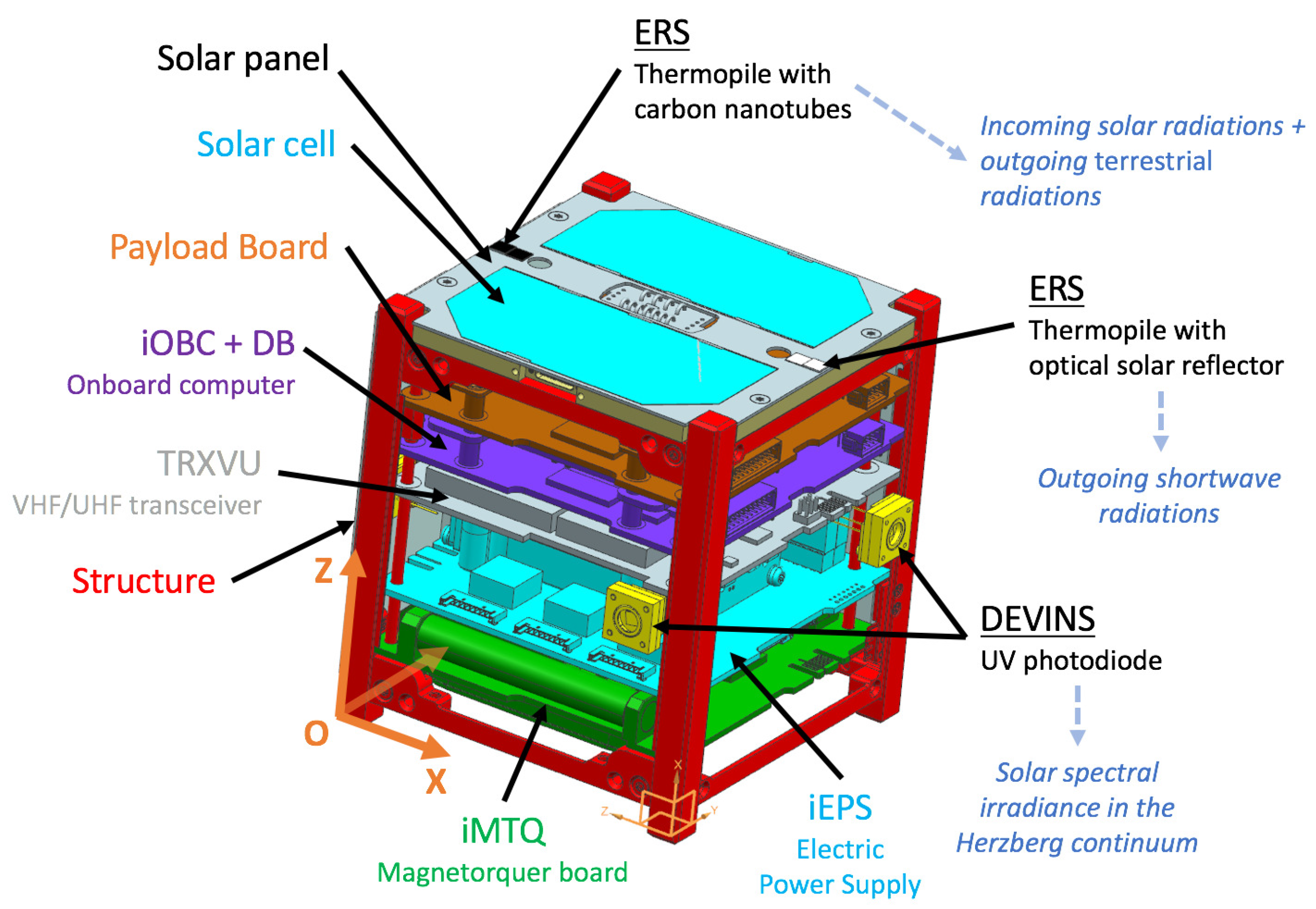
Figure 2.
UVSQ-SAT computer aided design representation with an arrangement of all Printed Circuit Boards (PCBs). The UVSQ-SAT payload instruments are shown (Earth Radiative Sensors (ERS) and DEep uV INnovative detector technologies for Space observations (DEVINS)), except the three axis accelerometer/gyroscope/compass, which is located above the payload electronic board.
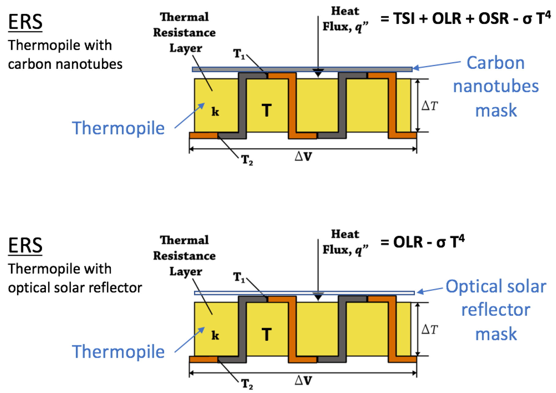
Figure 3.
Earth Radiative Sensors (ERS) measurement principle. On each side of UVSQ-SAT, there are these two sensors. TSI, Total Solar Irradiance; OLR, Outgoing Longwave Radiation; OSR, Outgoing Shortwave Radiation.
Figure 3.
Earth Radiative Sensors (ERS) measurement principle. On each side of UVSQ-SAT, there are these two sensors. TSI, Total Solar Irradiance; OLR, Outgoing Longwave Radiation; OSR, Outgoing Shortwave Radiation.
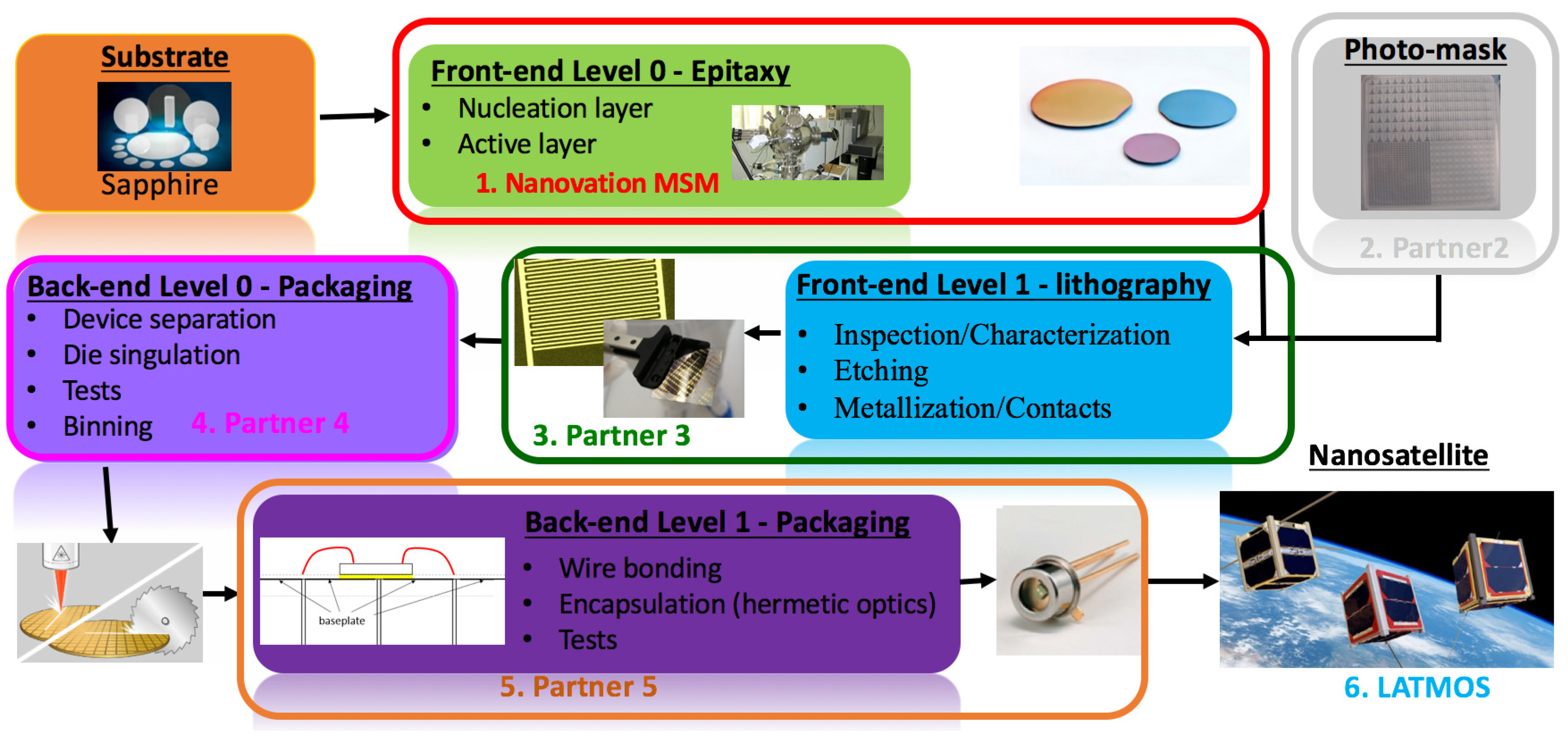
Figure 4.
DEVINS manufacturing process. This action (collaborative project between LATMOS, Nanovation, and Observatoire de Versailles Saint-Quentin-en-Yvelines) is co-funded by the French Agence Nationale de La Recherche (ANR).
Figure 4.
DEVINS manufacturing process. This action (collaborative project between LATMOS, Nanovation, and Observatoire de Versailles Saint-Quentin-en-Yvelines) is co-funded by the French Agence Nationale de La Recherche (ANR).
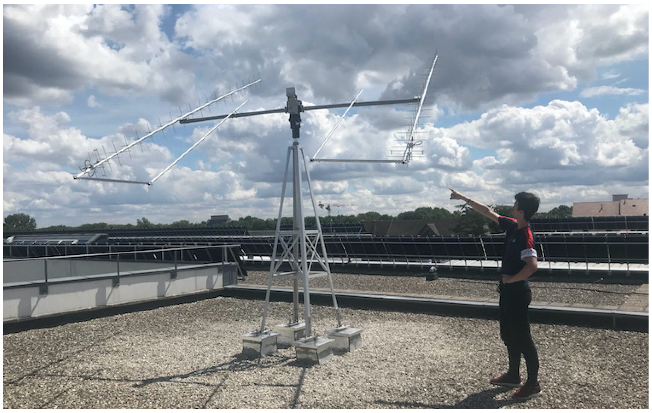
Figure 5.
UVSQ/LATMOS UHF/VHF station (one of the stations of the INSPIRE network). LATMOS hosts students from UVSQ and Paris Saclay universities to provide hands-on experience (satellite manufacturing, antenna realization, etc.).
Figure 5.
UVSQ/LATMOS UHF/VHF station (one of the stations of the INSPIRE network). LATMOS hosts students from UVSQ and Paris Saclay universities to provide hands-on experience (satellite manufacturing, antenna realization, etc.).
Figure 6.
Spatial reconstruction of Earth’s net radiation binned into a 1× 1 latitude-longitude geographic grid that will be obtained with UVSQ-SAT. The source of data for the left upper panel was from CERES observations.
Figure 6.
Spatial reconstruction of Earth’s net radiation binned into a 1× 1 latitude-longitude geographic grid that will be obtained with UVSQ-SAT. The source of data for the left upper panel was from CERES observations.
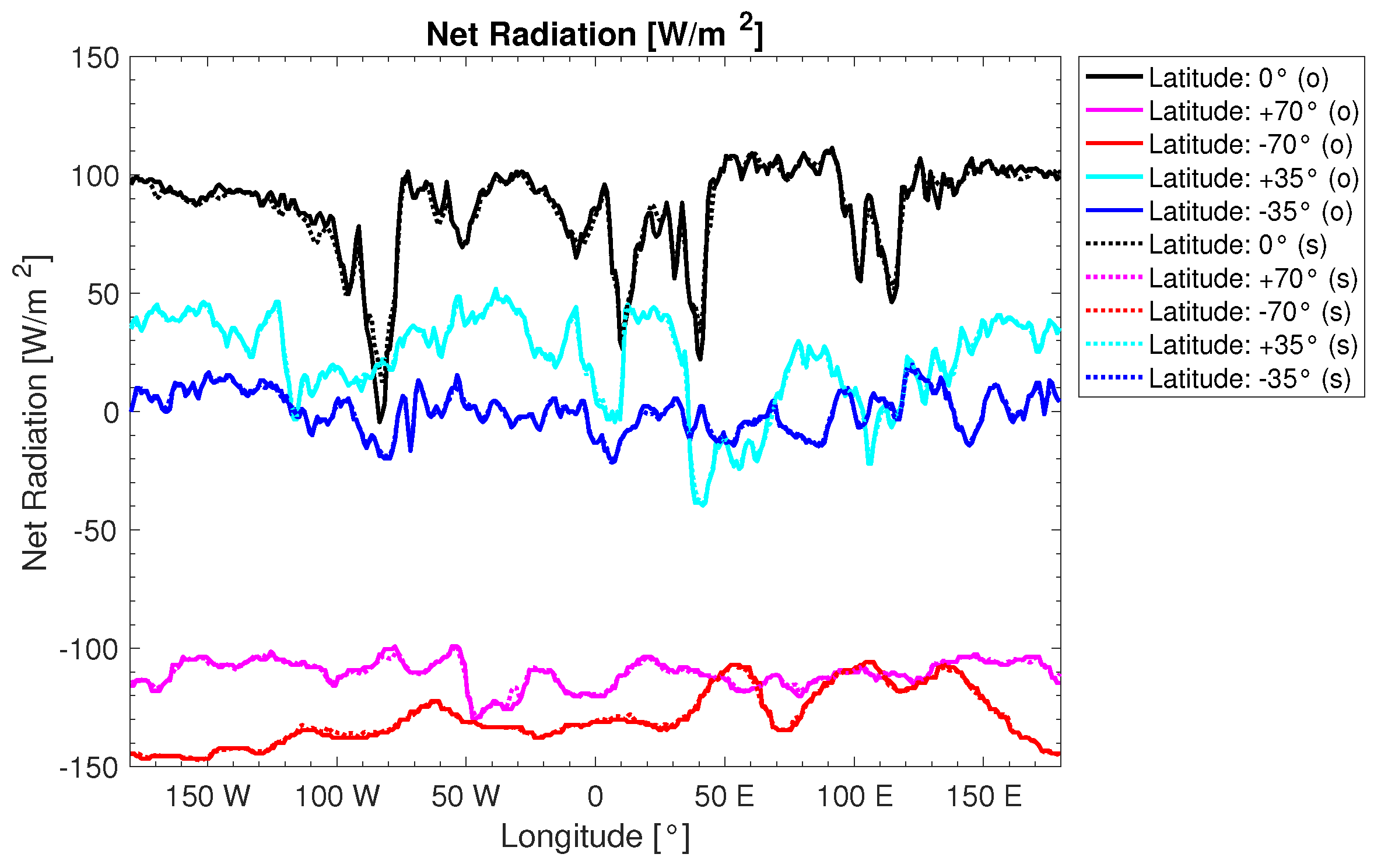
Figure 7.
Daily Earth net radiation as a function of longitude for different terrestrial latitudes. (o) represents the real observations (CERES data). (s) represents the results obtained with a simulation of observations from a virtual constellation of 15 satellites (five different inclinations and three different LTAN).
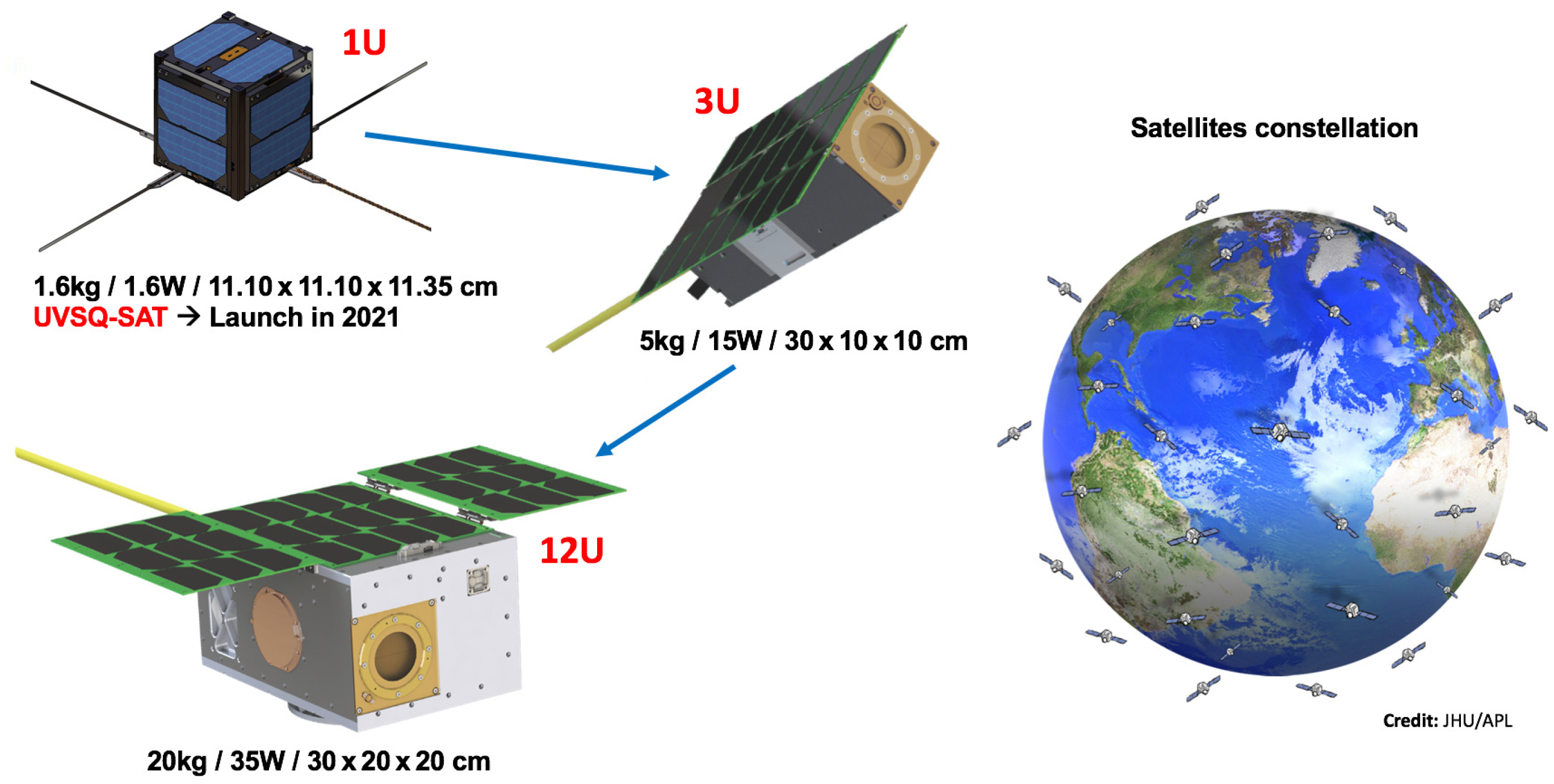
Figure 8.
From a very simple unitary CubeSat to an increasingly complex nanosatellite on which a small satellite constellation will be based.
Figure 8.
From a very simple unitary CubeSat to an increasingly complex nanosatellite on which a small satellite constellation will be based.
Table 1.
Scientific requirements for Earth’s energy imbalance and solar spectral irradiance in the Herzberg continuum (high scientific relevance and UltraViolet and infrared Sensors at high Quantum efficiency onboard a small SATellite (UVSQ-SAT) expected performances). EEI, Earth’s Energy Imbalance; SSI, Solar Spectral Irradiance.
| Requirements | Scientific Relevance | |
| Essential Climate Variable (ECV) | Absolute uncertainty | Stability per decade |
| EEI measurements | ±1 Wm at 1 | ±0.1 Wm at 1 |
| SSI at 215 nm | ±1.7 10 Wmnm | ±3.4 10 Wmnm |
| | ( ±0.5% at 1) | ( ±0.1% at 1) |
| Requirements | UVSQ-SAT Performances | |
| Essential Climate Variable (ECV) | Absolute uncertainty | Stability per year |
| EEI measurements | ±15 Wm at 1 | ±5 Wm at 1 |
| SSI at 215 nm | ±8.5 10 Wmnm | ±1.7 10 Wmnm |
| | ( ±2.5% at 1) | ( ±0.5% at 1) |
Table 2.
UVSQ-SAT CubeSat properties.
Table 2.
UVSQ-SAT CubeSat properties.
| Properties | Value | Comments |
|---|
| Orbit | SSO | Maximum altitude of 600 km, LTAN of 10:30 |
| Design lifetime | 1 year for LEO | 3 years desired |
| Launch date | Q4 2020/Q1 2021 | Launch vehicle: Soyuz |
| Size | 1U | 11.10 cm (X) × 11.10 cm (Y) × 11.35 cm (Z) |
| Mass | 1.6 kg | Maximum with margins |
| Solar cells | 12 | 3G30A solar cells provided by Azurspace |
| Batteries | 22.5 Wh at 8 V | 2 Panasonic batteries (NCR18650B) with heaters |
| Power generated | 2.2 W | Orbit average power per 1U area in LEO |
| Power consumption | 1.6 W | Maximum orbit average with margins |
| ADCS | 3 axis magnetometer | Measurements of the local Earth magnetic field |
| (Appendix A) | 3 axis magnetorquer | 0.2 Am magnetic dipole |
| | 6 SLCD-61N8 photodiodes | Coarse estimation of the Sun’s direction () |
| CDHS and OBC | 400 MHz, 32-bit ARM9 | Processor |
| (Appendix A) | 32 MB SDRAM | Synchronous Dynamic Random Access Memory |
| | 2×2 GB SD cards | Non-volatile Data Storage (SD card redundancy) |
| | 1 MB NOR flash memory | Code storage |
| | IC, SPI, UARTs | UART is only used for debugging iOBC |
| Data downlink | 1.2/9.6 kbps | UHF BPSK (437.020 MHz) communication |
| Data uplink | 9.6 kbps | VHF FSK (145.830 MHz) communication |
| Ground contact station | Less than 1 hour per day | LATMOS station |
| Redundancy stations | NCU (TW), ACRI-ST (FR) | Other stations: amateur radio partners |
| Downlink UVSQ-SAT data | 1.8 Mbyte per day | Maximum during a day |
| Uplink UVSQ-SAT data | 0.3 Mbyte per day | Maximum during a day |
| Transponder | Link with amateur radio | Live retransmission of FM signals |
| Payload | 12 ERS | EEI measurements |
| | 4 DEVINS | UV SSI measurements |
| | 1 Teach’ Wear (TW) sensor | Accelerometer, gyroscope, and compass |
| Launch adapter | ISIPOD or Quadpack | CubeSat deployer with a satellite mass up to 2 kg |
Table 3.
Error budget of the ERS sensor.
Table 3.
Error budget of the ERS sensor.
| Uncertainty Sources | Absolute Uncertainty | Determination Method |
|---|
| Emissivity (, ) | ±0.25% | Ground based calibration, BRDF |
| Absorptivity (, ) | ±0.25% | Ground based calibration, BRDF |
| Temperatures (, ) | ±0.01 Kelvin | Ground based calibration, in-flight validation |
| Voltage (, ) | ±50 nV | Ground based calibration, in-flight validation |
| Responsivity (, ) | ±0.25% | Ground based calibration, in-flight validation |
| Satellite altitude (z) | ±0.1% | Orbital assessment |
| ±0.5 Wm | Space based radiometers observations |
| d | ±0.05% | IMCCE determinations |
| ±0.1% | Calculations, IMCCE determinations |
| ±1% | Deep learning approach |
Table 4.
ERS technical requirements. For all sensors, it is necessary to monitor the Temperature (T) with a high accuracy to take into account the temperature radiation lost (Stefan–Boltzmann law).
Table 4.
ERS technical requirements. For all sensors, it is necessary to monitor the Temperature (T) with a high accuracy to take into account the temperature radiation lost (Stefan–Boltzmann law).
| Parameter | Requirements |
|---|
| ERS signal range | −500 Wm to +1500 Wm |
| | (−100 V per Wm to +300 V per Wm) |
| ERS resolution | 18 bits (∼1.5 nV) |
| ERS noise detection | ±0.25 Wm ( ±50 nV) |
| ERS time response | < 50 ms |
| Temperature range | −60 C to +90 C |
| Resolution | 18 bits (5.7 10 C) |
| Temperature noise | < ±0.1 C |
| Acquisition time | Better than 10 s |
Table 5.
ERS scientific requirements. Total solar irradiance is considered as accurately known.
Table 5.
ERS scientific requirements. Total solar irradiance is considered as accurately known.
| Parameter | Absolute Uncertainty | Stability per Year |
|---|
| OLR | ±10 Wm at 1 | ±1 Wm at 1 |
| OSR | ±10 Wm at 1 | ±5 Wm at 1 |
| TSI | ±0.5 Wm at 1 | < ±0.1 Wm at 1 |
| EEI = TSI/4 − (OLR + OSR) | < ±15 Wm at 1 | ∼±5 Wm at 1 |
Table 6.
DEVINS photodiodes’ technical requirements.
Table 6.
DEVINS photodiodes’ technical requirements.
| Parameter | Requirements |
|---|
| DEVINS signal range | 0 to 2.1 Wm (200–242 nm band) |
| | Target value: ∼1.4 Wm |
| Central wavelength | 220 ± 5 nm |
| Full width at half maximum | 20 ± 2 nm |
| Rejection | 10 in the 250–3000 nm band |
| DEVINS resolution | 18 bits (∼0.03 nA) |
| DEVINS noise detection | < 30 nA |
| DEVINS time response | < 20 ms |
| Acquisition integration time | Better than 10 s |
Table 7.
TW sensor technical requirements.
Table 7.
TW sensor technical requirements.
| Parameter | Requirements |
|---|
| TW signal range | Accelerometer: ±2 g |
| | Gyroscope: ±250 deg |
| | Compass: ±4912 T |
| TW resolution | 16 bits |
| TW noise detection | Accelerometer: 230 g/ |
| | Gyroscope: 0.015 deg/s/ |
| DEVINS time response | <20 ms |
| Acquisition integration time | 10 s |

