1. Introduction
With the development of society, location-based service became part of people’s lives. A pedestrian navigation and positioning service system mainly depends on a global positioning system (GPS) in an outdoor environment [
1,
2]. For indoor applications in, e.g., airports, train stations, underground garages, and shopping malls, GPS often becomes unavailable because of signal occlusion, which would hinder the application of location-based services in these areas. Therefore, pedestrian indoor navigation technology is critical to ensure the success of location-based services.
Currently, pedestrian indoor navigation and positioning can be achieved using two types of methods. The first type of method is based on wireless technologies, e.g., WiFi [
3,
4,
5], ultra-wideband (UWB) [
6,
7], visual sensors [
8], radio frequency identification (RFID) [
9], ibeacon [
10], Bluetooth, and/or ZigBee, with a multi-source information fusion technique [
11] to obtain pedestrian location information. For the first type of method, its location errors do not accumulate over time. However, these methods need a significant cost to deploy wireless devices as beacons before navigation and are infeasible for the unknown environment.
The second type of method is based on a pedestrian dead reckoning (PDR) algorithm using a micro-electro-mechanical system (MEMS) [
12]. In these methods, an inertial sensor is fixed on the foot [
13,
14], waist [
15,
16], leg, or shoulder of a user for data acquisition, in order to determine the position of pedestrian using the number and the size of walking steps and the heading angle [
17]. These methods belong to autonomous positioning technologies and have a high positioning accuracy in a short-time period. However, their positioning performance is drastically affected by the accumulative errors of iterative calculation. Therefore, many researchers are committed to solving the accumulative errors in the traditional PDR algorithm [
18,
19]. Zhou et al. [
19] proposed a PDR algorithm with low computational complexity using a foot-mounted inertial measurement unit (IMU) and estimating orientation of the foot based on extended Kalman filter (EKF), which can correct the accumulative errors of PDR. Nonetheless, it can only be applied for foot-mounted navigation and, therefore, has poor viability for different users.
The MEMS-based algorithm brings inconvenience to practical application due to the extra- installation of inertial sensors. In allusion to the inconvenience of pedestrian positioning technology based on fixed inertial sensors, smartphone-based pedestrian navigation gradually became a research hotspot for experts. Bilke et al. [
20] proposed a locating system based on recognizing geomagnetic field disturbances and ambient light. Li [
21] combined Bluetooth and an inertial navigation system to implement a set of navigation systems based on a smartphone. Kang and Han [
22] designed a smartphone-based algorithm, named smartPDR, but users had to reduce the sway of the smartphone in experiments. Wang et al. [
23] presented a PDR approach based on motion mode recognition using a smartphone. The motion mode recognition was achieved using a support vector machine (SVM) and a decision tree (DT), which thereby increased the complexity of the algorithm. Zeng et al. [
24] proposed an autonomous inertial heading correction algorithm based on the Kalman filter and the different usage modes of the smartphone, e.g., normal mode, landscape mode, or call mode. The usage mode could be determined based on the gravity-assisted (GA) method. However, in References [
22,
23,
24], step detection methods were both based on peak detection, which would introduce detection errors due to the step detection errors. Moreover, the step length estimation method was based on a nonlinear model or constant which would cause position errors for different users. Furthermore, mode recognition methods do not have universality, as the accuracy of these methods is affected by the configurations of the threshold.
The heading error is the one of the main error sources in PDR. In References [
20,
21,
22], smartphone-based navigation algorithms required users to hold a smartphone in a fixed mode as long as possible. However, it is difficult for users to keep a fixed mode during the movement process, which leads to significant heading errors. Wang et al. [
23] proposed a principal component analysis (PCA)-based method with global accelerations (PCA-GA) to infer pedestrian headings. However, one set of experiments represented only one phone pose, which is not applicable to multi-mode changes of a smartphone. Although Reference [
24] proposed using a Kalman filter to correct the heading errors in a multi-mode application, heading correction values are hard to estimate precisely due to weak constraints and observation errors.
In this paper, we propose a novel pedestrian dead reckoning algorithm for multi-mode recognition based on a smartphone. Firstly, different from the peak detection in References [
22,
23,
24], state transition was carried out to improve the accuracy of step detection for different phone modes. Secondly, we adopted the neural network to obtain the step length and the smartphone mode without setting thresholds manually, which increased the universality of step length estimation and mode recognition methods. The main contributions of the paper are that we design the heading correction method based on zero angular velocity (ZA) and an overall correction method based on lateral velocity limitation (LV) to correct the error of heading estimation and inertial sensors in a smartphone-based PDR. Experimental results show that the algorithm proposed in this paper is effective.
The rest of the paper is organized as follows:
Section 2 presents our proposed algorithm in detail, including the comparison between the traditional PDR algorithm and the proposed novel PDR algorithm, along with the step detection, step length estimation, multi-mode intelligent recognition, and heading correction methods. The experimental results are systematically analyzed in
Section 3.
Section 4 and
Section 5 discuss the system and draw conclusions.
2. Materials and Methods
2.1. Proposed System Scheme
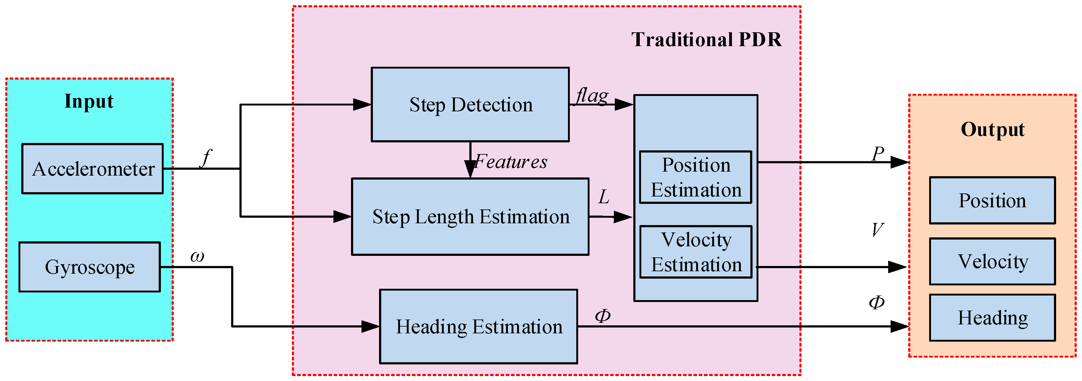
As shown in
Figure 1, using an accelerometer and a gyroscope, the traditional scheme of the PDR algorithm estimates the position, velocity, and heading using the results of step detection, step length estimation, and heading estimation.
In
Figure 1,
f and
are the outputs of the accelerometer and gyroscope, respectively,
flag indicates the result of step detection,
L is the step length estimation, and
Ф is the heading estimation of the pedestrian. Pedestrian navigation involves a body coordinate system and a navigation coordinate system. The
x-axis of the body coordinate system corresponds to the lateral direction of the smartphone, the
y-axis corresponds to the forward direction of the smartphone, and the
z-axis satisfies the right-hand rule. The navigation coordinate system involves east, north, up (ENU) coordinates.
The traditional heading estimation method uses a
z-axis gyroscope
, denoted by
where
and
are the headings at time instants
kT and (
k − 1)T, respectively. The initial heading is set manually.
The traditional position estimation method is resolved using the step length
Li and the heading of the
i-th step, denoted by
The velocity estimation method is calculated by
where T represents sampling period,
and
are the lateral acceleration and forward acceleration on the horizontal plane at time instants
kT, and
and
are the eastward acceleration and northward acceleration at time instants
kT. Then, the eastward velocity and northward velocity are calculated by
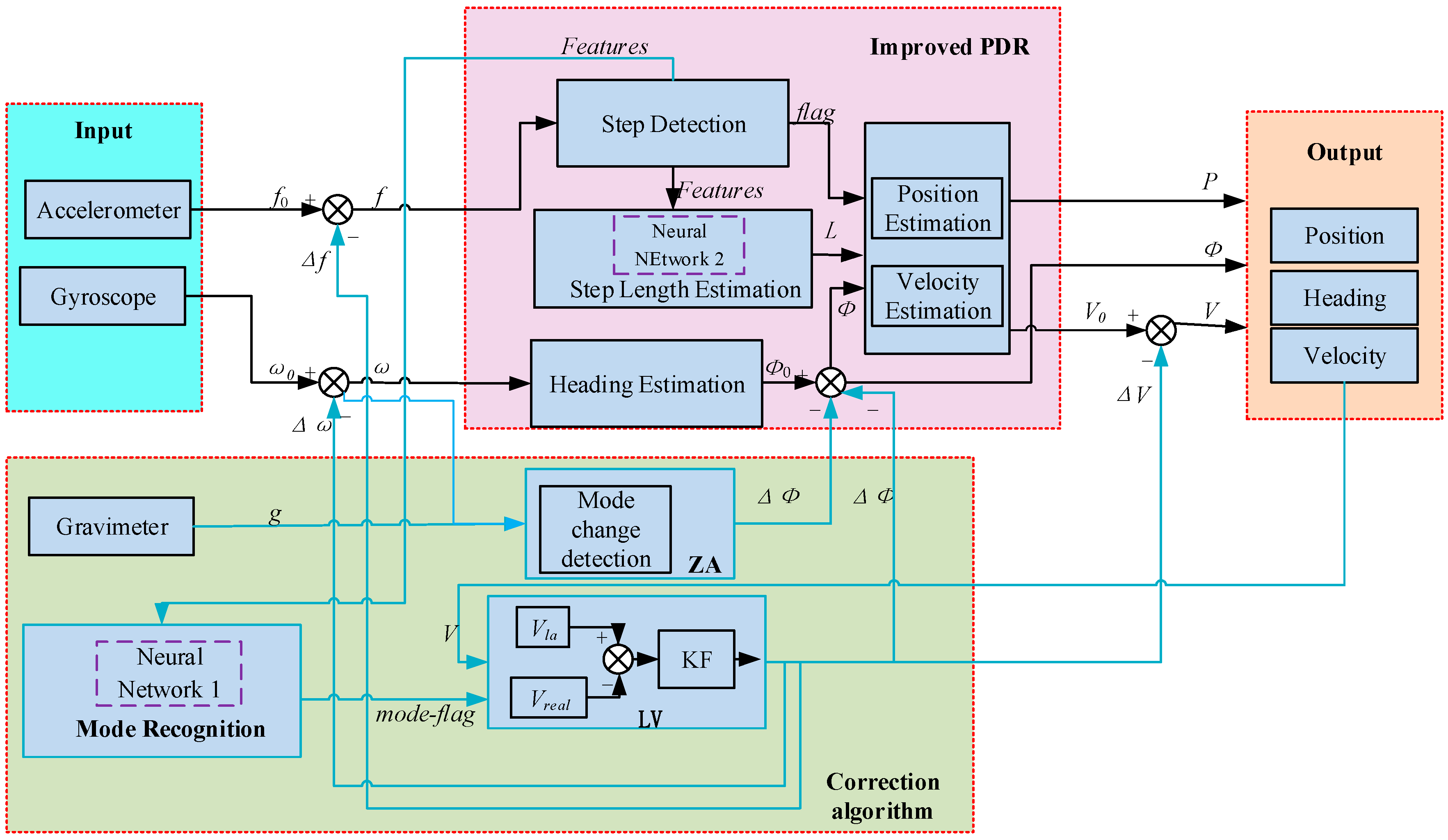
The accurate estimations of step, step length, and heading are crucial for a pedestrian navigation algorithm. Since the accuracy of built-in inertial sensors in a smartphone is at a lower level, the traditional PDR algorithm would have relatively large navigation errors; in particular, the drift of heading can result in a drastic increase in errors. In addition, considering the user experience, this paper studies a multi-mode smartphone-based navigation algorithm. In order to solve the defects of the traditional PDR algorithm, we propose a novel PDR algorithm, which includes step detection based on state transition, a step length estimation method based on neural network and differential GPS, and multi-mode intelligent recognition, a heading correction method based on zero angular velocity (ZA), and an overall correction method based on lateral velocity limitation (LV), as shown in
Figure 2. In the figure, the purple dotted boxes represent the neural networks which are outlined by different features. We estimate the results directly using these neural networks in a PDR algorithm. Specific algorithm theories are shown in
Section 2.2,
Section 2.3,
Section 2.4,
Section 2.5 and
Section 2.6.
2.2. Step Detection Based On State Transition
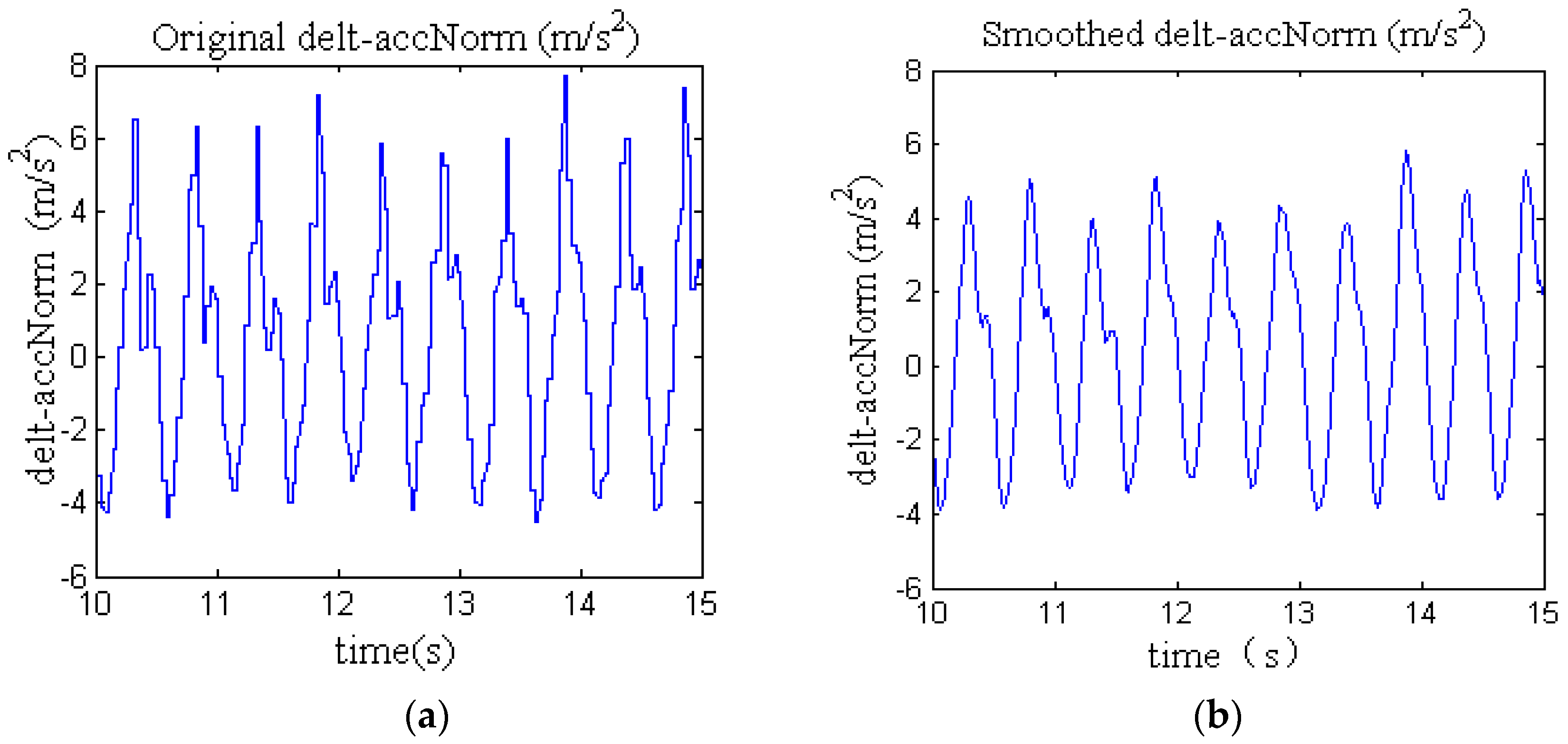
During the walking process of the human handheld smartphone, the lifting and undulating of the foot cause the lifting and undulating of the human body. This cyclical fluctuation is reflected in the acceleration of the smartphone, as shown in
Figure 3a. The delt-accNorm in
Figure 3a represents the differences between the acceleration modulus and the modulus of the pedestrian’s initial stationary stage, denoted by Equation (5). The purpose of the differences is to reduce the difference of the threshold of step detection between different pedestrians. In view of the noise of the accelerometer in the course of motion, the curve burr as shown in
Figure 3a will reduce the accuracy of step detection. Thus, we smooth out the interference of acceleration using a moving average filter shown in Equation (6). The smoothed result is shown in
Figure 3b.
where
,
, and
represent three-axis acceleration at time instants
iT, while
,
, and
represent the mean value of the three-axis acceleration at the initial stationary stage.
represents the delt-accNorm at time instant
kT, n is the size of the sliding window, and T is the sampling period.
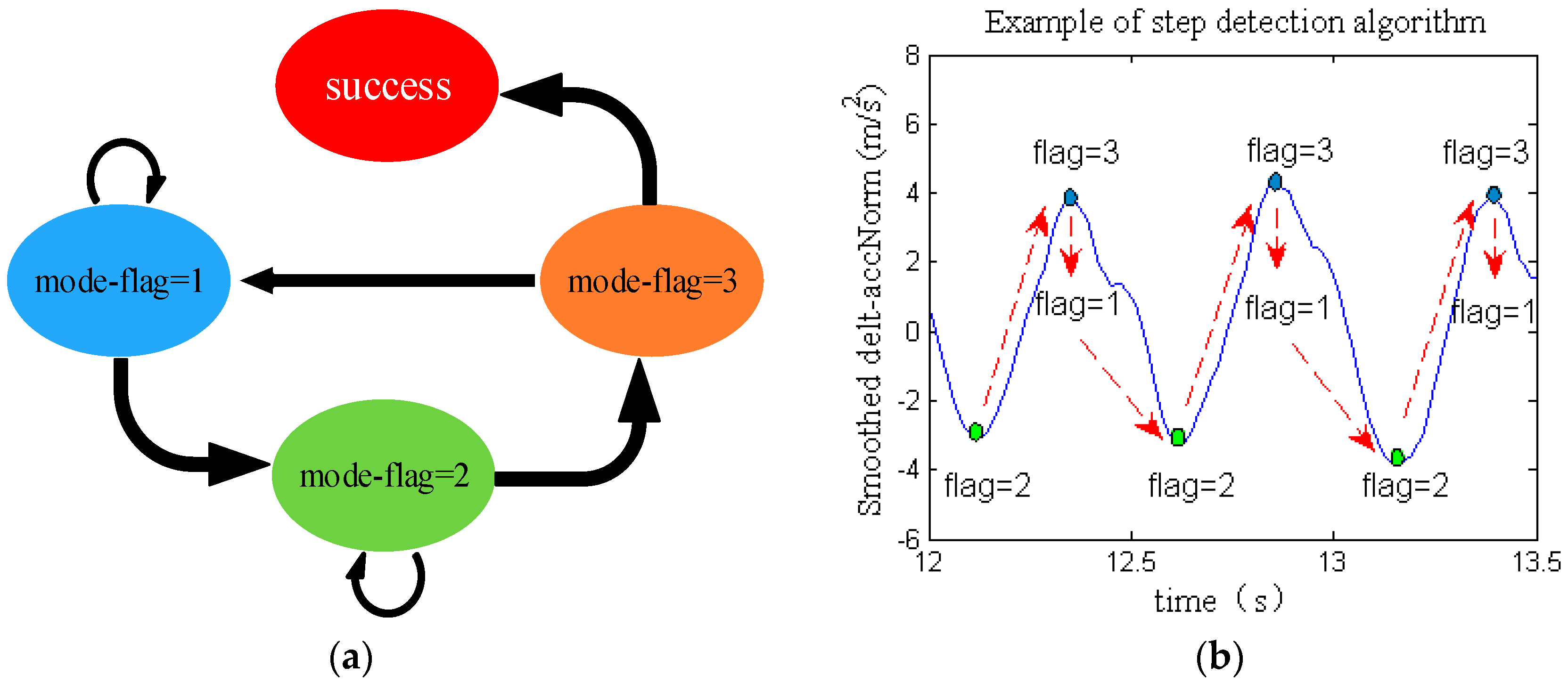
The valley value and the peak value of delt-accNorm are taken as the conditions of step detection. The specific models are as follows:
- (1)
Peak value detection: if , then the mode-flag is set to 1.
- (2)
Valley value detection: if , and the time difference between the last peak and the valley value satisfies , then the mode-flag is set to 2.
- (3)
On the basis of (2), the next peak detection is carried out, and if the time difference between the last valley and this peak value satisfies , then the mode-flag is set to 3.
- (4)
When the mode-flag is 3, it represents that we detected one step successfully. Then, the mode-flag is set to 1 and the cycle is repeated.
,
,
, and
are the detection thresholds of peak value, valley value, the time difference between the last peak and the current valley value, and the time difference between the last valley and the current peak value, respectively. The process of step detection is shown in
Figure 4.
The difference between the handheld and the foot-fixed smartphone-based navigation algorithm is that the latter has an obvious zero velocity interval [
13], while the former has only very short zero velocity moments. The zero velocity moment of the handheld smartphone-based navigation is the first sampling period which is less than the modulus value of the initial stationary stage after the peak appears. Meanwhile, the zero velocity flag is set to 1. Moreover, in order to reduce the cumulative errors of velocity, the velocity of that moment is set to zero.
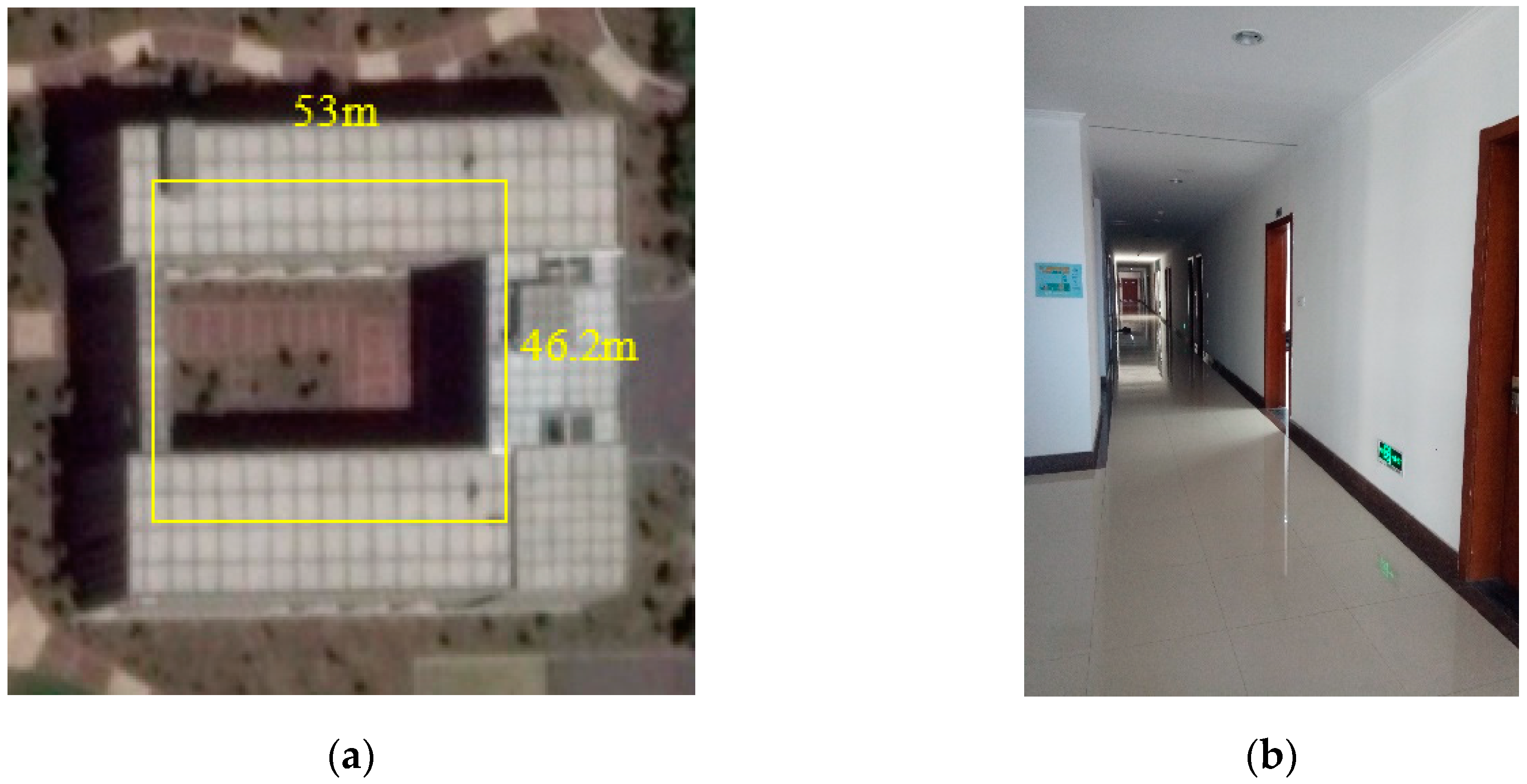
In order to verify the accuracy of the step detection method, we carried out three experiments, and the experimental routes included a straight line and a rectangular path in an indoor corridor. In
Table 1, “actual” means the actual steps and “algorithm” represents the results of the proposed algorithm. In summary, the average accuracy of the step detection method could reach 99%.
2.3. Step Length Estimation Method Based on Neural Network and Differential GPS
The step length of the pedestrian is affected by factors such as height, step frequency, and environment. Based on the human motion model and the acceleration data collected, it was found that peak values, valley values, and the time differences between contiguous peak values of delt-accNorm are closely related to the step length estimation. In this paper, we constructed a three-layer neural network with four nodes in the input layer, one node in the output layer, and 12 nodes in the hidden layer. The inputs of the model were , , , and . The output of the model was the step length, calculated using the position of a high-precision differential GPS. To solve the problem whereby the estimation accuracy of traditional step length estimation methods differs from that of different users with different velocities, we collected training data from different users walking fast and normally to ensure the diversity of the training data and to improve the applicability of the method. Furthermore, the transfer functions of the hidden layer and the output layer were a tangent sigmoid function (tansig) and a pure linear function (purelin). The backprop network training function was the Levenberg–Marquardt backpropagation (BP) function (trainlm), and the backprop weight/bias learning function involved BP learning rules with a momentum term (learngdm). The weight initialization strategy of the network satisfied a random distribution between −1 and 1. In addition, the target error, the learning of neural network, and the time of training were set as 0.001, 0.1, and 5000, respectively.
In the training stage, we firstly normalized input data and output data, i.e., the acceleration characteristic information and the step length, respectively. Then, the backpropagation (BP) neural network was trained.
In the test stage, we input real-time acceleration characteristic information and calculated the step length using the trained neural network.
To highlight the advantages of the proposed step length estimation method, we compared it with the traditional non-linear method in Reference [
3]. The experimental route was a 54.3-m straight line, and four experiments were carried out. The results are shown in
Table 2. We can see that the error of the proposed method was obviously smaller than that of the nonlinear method.
2.4. Multi-Mode Intelligent Recognition
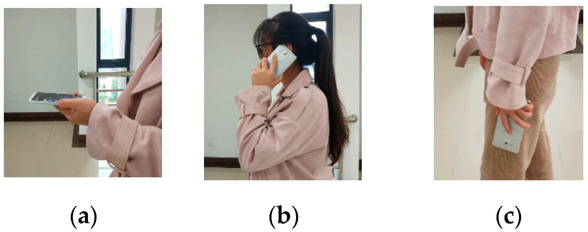
In addition to the normal mode of a handheld smartphone, the phone mode and the swinging-hand mode were also studied, as shown in
Figure 5.
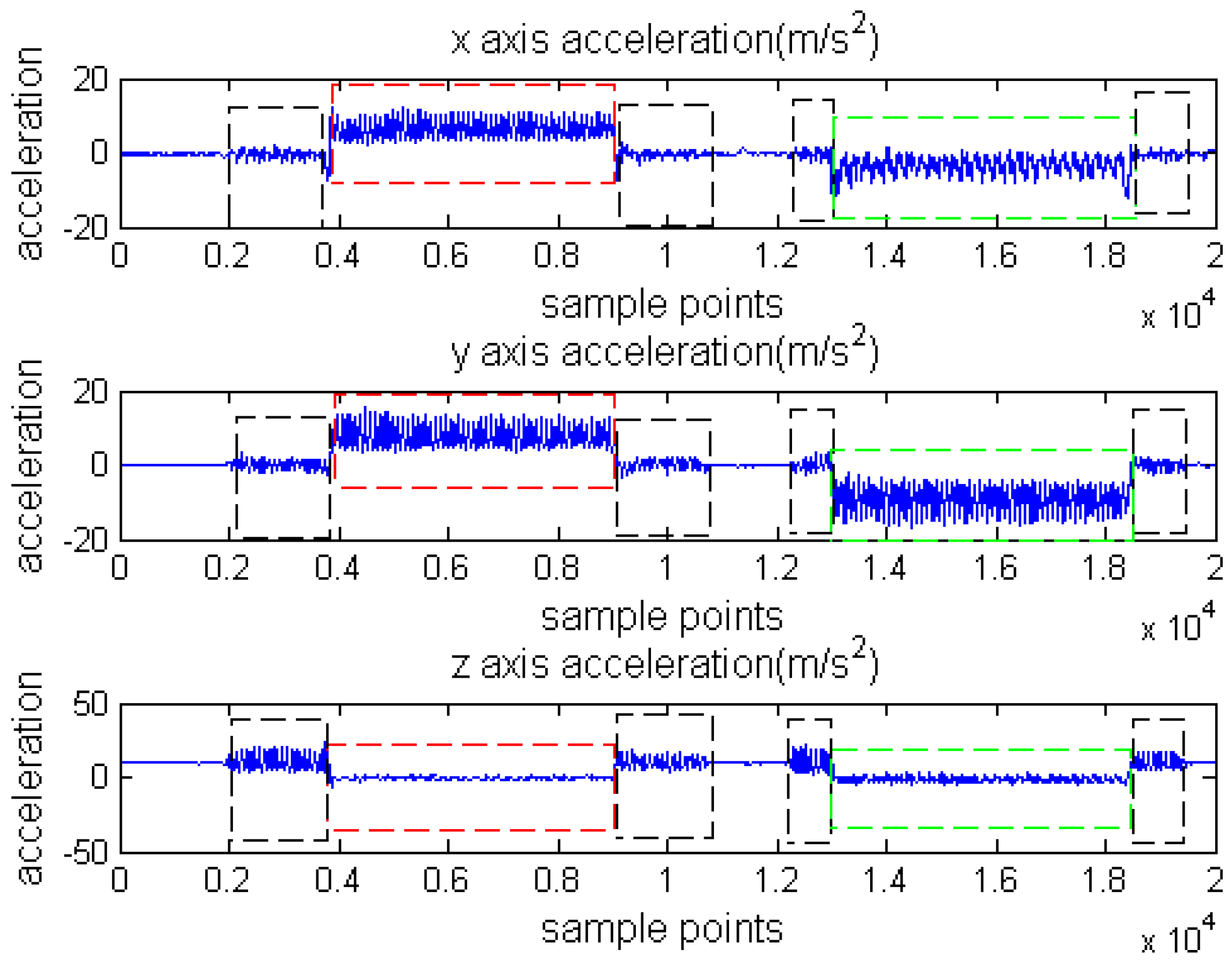
In consideration of the different induction characteristics of sensors corresponding to different modes, we analyzed the differences of triaxial sensors using the three modes. The acceleration data are shown in
Figure 6, where the mode in the black dotted rectangle is the normal mode, the mode in the red dotted rectangle is the phone mode, and the mode in the green dotted rectangle is the swinging-hand mode.
Traditional mode recognition methods mainly include a decision tree and SVM. We need to accurately analyze the data characteristics of different modes and set accurate thresholds when using the decision tree method. When using the SVM method, we need to determine the appropriate kernel function and provide a large amount of storage space. The above two methods have certain limitations; thus, we propose a mode recognition method based on the BP neural network. This paper not only takes
,
,
, and
as characteristic variables, but also extracts the
x-axis acceleration variation between the current step and the previous step, the
x-axis acceleration mean value, and the standard deviation of the current step to form a seven-dimensional input vector. The neural network had three layers. There were seven nodes in the input layer, ten nodes in the hidden layer, and one node representing the phone-flag in the output layer. The transfer function, backprop network training function, and backprop weight/bias learning function of the network were the same as those in
Section 2.3. The weight initialization strategy of the network satisfied a random distribution between −1 and 1. In addition, the target error, the learning of the neural network, and the time of training were set as 0.01, 0.1, and 1000, respectively.
In the training stage, the feature values of each step were extracted as inputs, and the phone-flag was set as the output, i.e., the corresponding phone-flags for normal mode, phone mode, and swinging-hand mode were set as 1, 2, and 3, respectively. Then, we normalized the training data and obtained a trained neural network.
In the test stage, we input real-time feature data, and the trained neural network was utilized to obtain the phone-flag.
In order to prove the accuracy of this method, we carried out four smartphone mode changing experiments in the indoor corridor. The actual phone-flag order was 1–2–1–3–1–2–1–3–1. The accuracy of the multi-mode recognition is shown in
Table 3, with an average accuracy of 99.58%.
2.5. Heading Correction Method Based on Zero Angular Velocity
The traditional method of heading estimation is shown in Equation (1), which is only applicable to the state of a smartphone plane parallel to the horizontal plane. In view of the large attitude angle errors caused by different smartphone modes when users walk, if not corrected, the heading errors will increase. Therefore, the first step of the heading correction method based on zero angular (ZA) velocity (ZA) algorithm was horizontal alignment. In this paper, the attitude conversion matrix of horizontal alignment was calculated using gravimeter data.
The pitch angle
and the roll angle
were calculated based on the data of three-axis gravitational acceleration
, where
g is the gravitational constant, denoted by
The acceleration and the angular velocity were projected to the horizontal coordinate by pitch angle and roll angle, denoted by
where
b represents the body coordinate system and
hor represents the horizontal coordinate system obtained by the projection.
and
are the attitude conversion matrices, denoted by:
During pedestrian movement, there are two situations that cause a large heading change. One is the pedestrian turning process, and the other is the mode switching process. If the z-axis horizontal angular velocity recurs directly, a heading error caused by the mode switching will be introduced. Therefore, the second step of the ZA algorithm was to detect the mode switching state and correct the z-axis horizontal angular velocity.
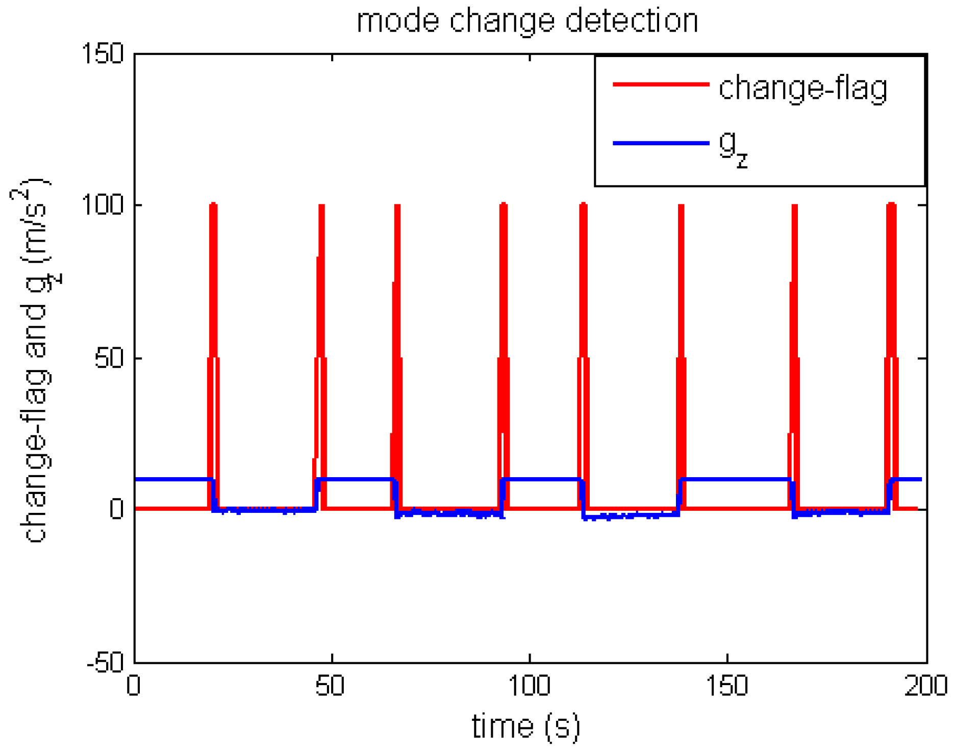
Because of the misjudgment of the mode recognition algorithm, it is limited to judging the smartphone mode switching state only through the results of
Section 2.4. In order to accurately detect the mode switching state, we analyzed the
z-axis gravity of the body coordinate system, as shown by the blue line in
Figure 7. We can see that the
z-axis gravity changes significantly when the smartphone mode switches, which is due to the axis inconsistency of induced gravity acceleration at different smartphone modes. However, the
z-axis gravity will not change dramatically when the user makes a turn. This is because the handheld smartphone mode is in a fixed mode. We took the
z-axis gravity variation as the characteristic quantity of mode switching. The mode change detection algorithm is shown in Equation (10), where
represents the
z-axis gravity variation between the current step and the previous step, and
represents the threshold of gravity variation.
In
Figure 4, the red line represents the change-flag of mode switching. It is known that the detection algorithm is accurate and there is no misclassification. When mode switching is detected, the
z-axis angular velocity is set to zero to reduce the heading error caused by mode switching.
In addition, when the heading angle changes significantly, it must be a turning state based on the fixed mode, as shown in Equation (11), where
means the heading variation between the current step and the previous step, and
represents the threshold of heading variation, which we set to 20.
2.6. Overall Correction Method Based on Lateral Velocity Limitation
The ZA algorithm only corrects the heading error caused by the mode switching, but not the error caused by a slight sway of the smartphone in the fixed mode. Especially in the phone mode and the swinging-hand mode, the heading errors caused by the sway of a handheld phone are more obvious. Since there is no lateral motion when the user walks straight, a virtual measurement of zero lateral velocity was constituted, and an overall correction algorithm based on lateral velocity constraint was established. Furthermore, on the basis of step detection in
Section 2.2, when it is not the zero velocity moment, we propose to use the overall correction method based on lateral velocity limitation to correct the navigation errors.
The seven-dimensional kalman filter state vector was constructed as follows:
where
is the heading error, [
;
] are the eastward velocity error and the northward velocity error, respectively, [
;
] are the zero bias and the random error of the first-order Markov process of the
z-axis gyroscope, and [∇
rx; ∇
ry] are the random errors of the first-order Markov process of the
x-axis and the
y-axis accelerometers.
The state equation is denoted by
where
A is the system matrix,
G is the system noise covariance matrix, and
W is the system noise. These three matrices are calculated using a recursive model based on PDR as
and are the time variables of the first-order Markov of gyroscope and accelerometer, respectively.
Lateral velocity
is a measurement, which is calculated from eastward velocity and northward velocity as
Equation (15) is obtained from a linearization of Equation (14).
The measurement equation is denoted by
where
is the actual lateral velocity, i.e.,
is zero. The measurement matrix H is calculated using Equation (14). The measurement noise
is the additional lateral velocity error caused by the sway of the smartphone and is considered white noise. For different smartphone modes, the additional lateral velocity is different. Thus, we set the measurement noise of the normal mode to 0.4, and the measurement noise of the phone mode and the swinging-hand mode to 0.9 in order to improve the filtering accuracy.
4. Discussion
The proposed pedestrian dead reckoning algorithm based on smartphone mode recognition uses only the built-in sensor of a smartphone. In comparison to Wi-Fi/UWB-based wireless indoor positioning technologies and the MEMS-based PDR algorithms, this algorithm possesses advantages of low-cost deployment and easy data acquisition. The algorithm can be applied in areas where wireless positioning signals are blocked or not available. The step detection method proposed in this paper has capabilities to not only detect the user’s step frequency, but also to locate the short zero velocity moment in the pedestrian navigation process accurately, which underpins the velocity correction. The proposed step length estimation method has high viability. The step length can be accurately estimated for different users, and the error is obviously smaller than the commonly used nonlinear step length estimation method in Reference [
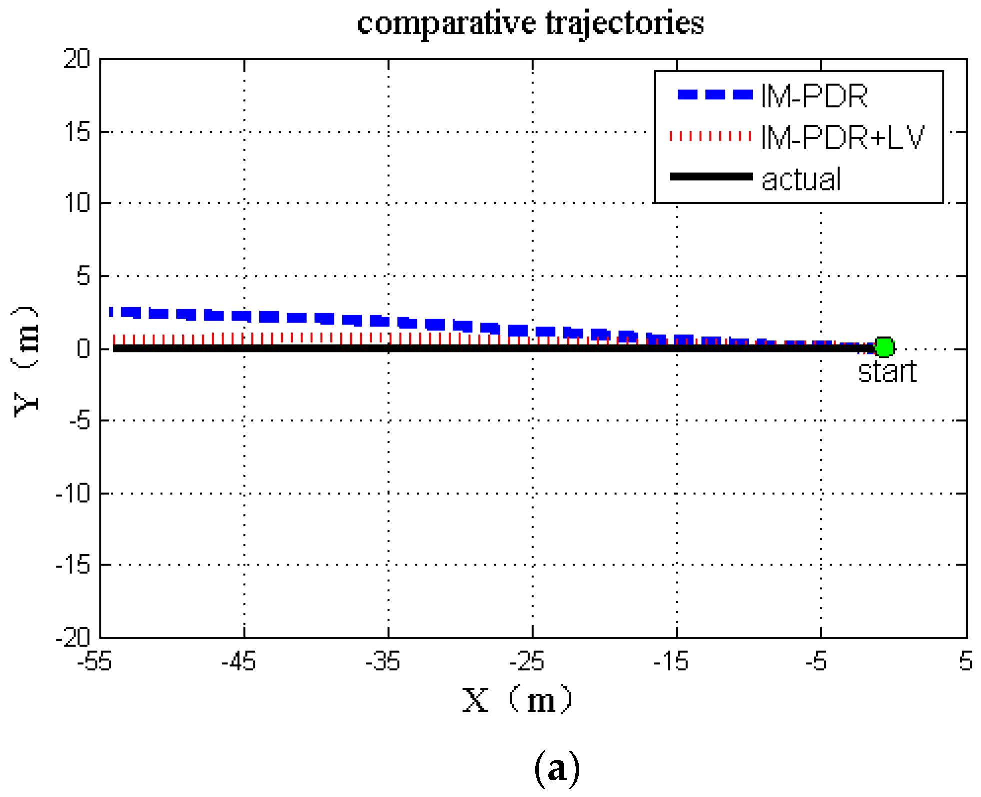
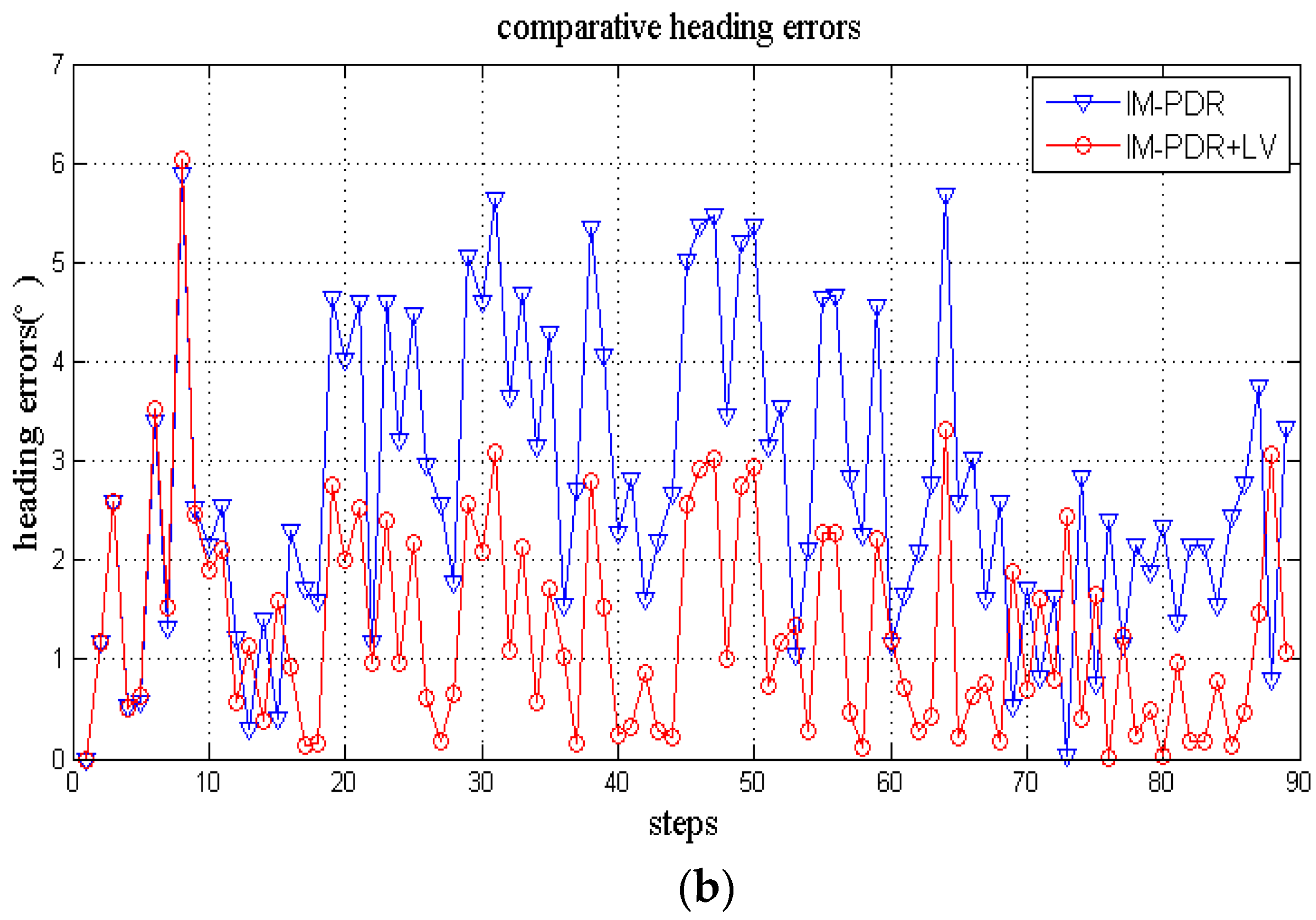
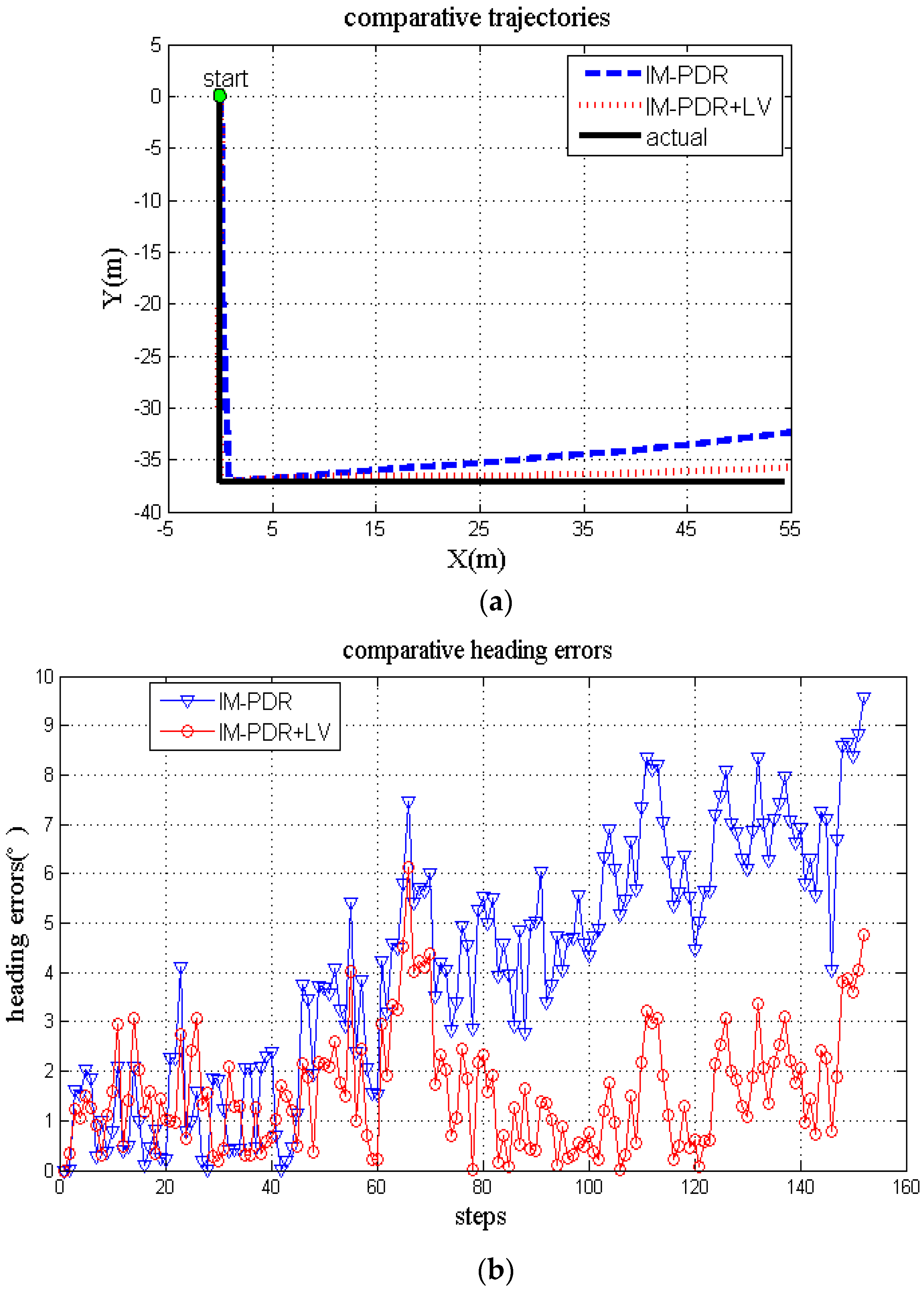
23]. Aiming at smartphone applications in multiple modes, a multi-mode intelligent recognition method based on a neural network was studied, which can accurately recognize three commonly used smartphone modes, including the normal mode, the phone mode, and the swinging-hand mode. To demonstrate the effectiveness of the heading correction method based on zero angular velocity and the overall correction method based on lateral velocity limitation, we performed two types of experiments. Firstly, when the smartphone mode was fixed, the LV algorithm was added to the improved PDR algorithm in order to correct the heading angle errors caused by the shaking of the handheld smartphone with an average heading error 65.65% less than that of the improved PDR algorithm. Secondly, in the case of the multi-mode environment, the novel pedestrian dead reckoning algorithm proposed was adopted. Its maximum errors accounted for 0.6–1.2% of the total path length, and the average heading errors were less than the results of the PDR algorithm proposed in Reference [
24].
However, the proposed algorithm also has a few limitations. Firstly, since there is no external sensor assistance, the initial heading angle can only be configured manually. The magnetic information could be considered as the initial heading estimation. Secondly, three commonly used smartphone modes were analyzed, i.e., the normal mode, the phone mode, and the swinging-hand mode. More smartphone modes, such as those involving the phone in pockets and bags, need to be further studied using similar methodologies. Finally, this algorithm focuses on the normal walking state. Other pedestrian motion states such as standing, running, and climbing up and down stairs can be studied in the future to construct a more viable pedestrian positioning and navigation algorithm.


