Abstract
The Luojia 1-01 Satellite (LJ1-01) is the first professional night-light remote-sensing satellite in China, and thus, it is of pioneering significance for the development of night-light remote sensing satellites in China and the application of remote sensing in the social and economic fields. To ensure the application of night-light remote-sensing data, several studies concerning on-orbit geometric calibration and accuracy verification have been carried out for the complementary metal oxide semiconductor (CMOS) rolling shutter camera of LJ1-01 since the launch of the satellite. Owing to the lack of high-precision nightlight geometric reference at home and abroad, it is difficult to directly calibrate the nighttime light image of LJ1-01. Based on the principle of rolling shutter dynamic imaging, a rigorous geometric imaging model of the time-sharing exposure of the rolling shutter of LJ1-01 is established, and a geometric calibration method for daytime imaging calibration and compensated nighttime light data is proposed. The global public Landsat digital orthophoto image (DOM) with a 15-m resolution and 90-m Shuttle Radar Topography Mission digital elevation model (SRTM-DEM) are used as control data. The images obtained in England, Venezuela, Caracas, Damascus, and Torreon (Mexico) were selected as experimental data. The on-orbit calibration and accuracy verification of LJ1-01 were carried out. Experiments show that after on-orbit geometric calibration, the daytime calibration parameters can effectively compensate for the systematic errors of night-light images. After compensation, the positioning accuracy of night-light images without geometric control points (GCPs) is improved from nearly 20 km to less than 0.65 km. The internal accuracy of the calibrated night-light images is better than 0.3 pixels, which satisfies the requirement of subsequent applications.
1. Introduction
Launched on 2 June 2018, Luojia 1-01 (referred to as LJ1-01) is the first scientific experimental satellite launched by Wuhan University. LJ1-01 has the functions of night-light remote sensing [1,2] and navigation augmentation [3]. Furthermore, it is used for remote-sensing applications in social and economic fields [4] and low Earth orbiter (LEO)-based navigation augmentation experiments. LJ1-01 is located in a 645-km solar synchronous orbit, and it is equipped with a high-sensitivity planar array complementary metal oxide semiconductor (CMOS) [5] night-light camera and a navigation enhancement test payload [3]. The noctilucent camera has an effective detector of 2048 × 2048, an imaging resolution of 129 m, an imaging width of 264 km, and strong global data acquisition capability. In addition, the LJ1-01 satellite platform is equipped with a GNSS receiver (supporting Global Positioning System (GPS) and Beidou) for measuring and transmitting the satellite position and velocity. Moreover, two star sensors and gyroscopes are installed on the platform. In the satellite imaging stage, a single/double star sensor on the satellite is employed for attitude measurement, and the parameters of the star sensor and gyro measurement are finally transmitted to the ground. The transmission frequency of the on-board GNSS and attitude data is determined by the frame period, with a maximum value of 1 Hz and a minimum value of 0.2 Hz. The main parameters of LJ1-01 are as listed in Table 1:

Table 1.
Satellite parameters of LJ1-01.
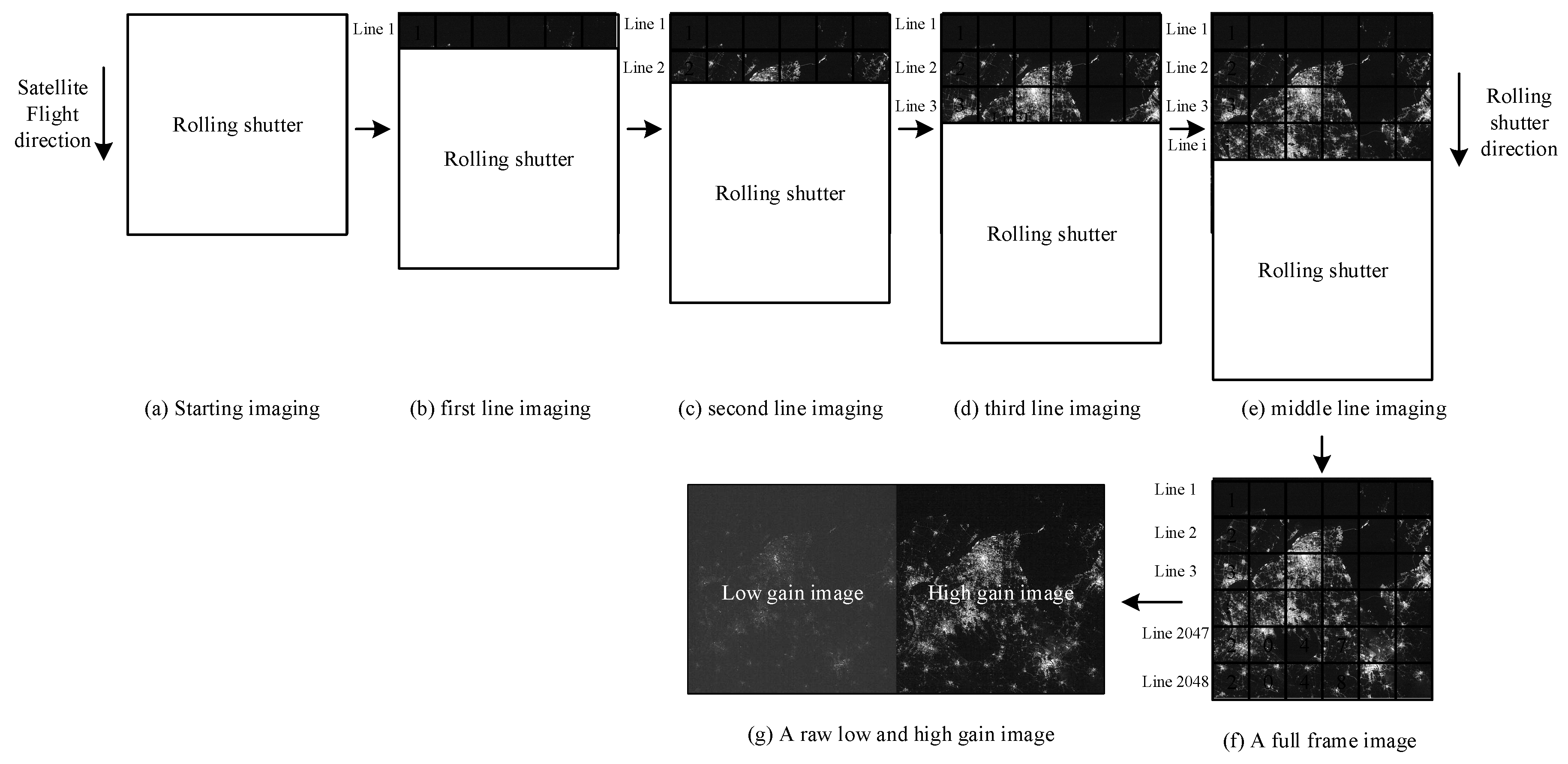
To carry out on-orbit geometric calibration of the LJ1-01, the satellite is designed to support both daylight and night imaging. To ensure optimal imaging in different imaging modes, daytime and nighttime imaging use different combinations of imaging parameters. During daytime imaging, the sensor uses a combination of low-level gain and short exposure time. The low-level gain data is valid and the high gain data is saturated in daytime imaging scenarios. At night, the sensor uses a combination of low-level gain and long exposure time, and both high and low gain data are effective in nighttime imaging scenarios. However, irrespective of whether daytime or night imaging is being performed, the nighttime sensor of LJ1-01 uses an electronic rolling shutter exposure mode [6,7,8]. As shown in Figure 1, each instantaneous exposure images one row of a single frame. The 2048 rows of detectors are exposed sequentially, and a full frame data is recorded after all row detectors are exposed. Figure 1e represents the intermediate process of rolling shutter imaging, and Figure 1f represents the complete frame of rolling shutter imaging.

Figure 1.
Schematic of rolling shutter imaging of LJ1-01 sensor.
On-orbit geometric calibration is the key link to ensure the quality of night-light remote sensing data of the LJ1-01 satellite. In this study, first, considering the exposure characteristics of the rolling shutter of LJ1-01, a rigorous geometric model of LJ1-01 was established. Furthermore, according to the error characteristics of the exterior orientation and internal orientation elements of LJ1-01, the geometric calibration model was established, and the calibration methods of daytime calibration and night imaging compensation were proposed. In addition, the theoretical accuracy of LJ1-01 satellite after calibration was analyzed according to the design index of the satellite platform. In the experimental part, public DOM (Landsat with a resolution of 15 m) and SRTM-DEM (Shuttle Radar Topography Mission (90-m-SRTM) digital elevation model) were used as the control data. The images from Torreon (Mexico), Caracas, Venezuela, Damascus, and England were selected as experimental data to carry out the on-orbit geometric calibration and validation of LJ1-01 sensors. Finally, the positioning accuracy of night-light images without geometric control points (GCPs) was noted to be better than 0.65 km, and the internal accuracies of the calibrated night-light images were better than 0.3 pixels.
2. Methods
Although the night-light payload of LJ1-01 is designed as a CMOS array load, its imaging process adopts the time-sharing exposure mode of the rolling shutter [7,9]. The exposure process is shown in Figure 2.
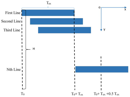
Figure 2.
Schematic of rolling shutter exposure process and exposure time.
In Figure 2, the x axis represents the starting time of exposure, starting from , the y axis represents the imaging line; represents an exposure time; represents the time interval between the capture of two frames and the can be adjusted in orbit; represents the height of the CMOS array; represents the number of lines exposed simultaneously, which means that the exposure is started at the line after the end of the first line of exposure. The process can be defined as follows: Each line is sequentially exposed, and the exposure time of each line is the same. According to the derivation, the imaging time of line is as follows.
satisfies the following equation.
To ensure that the daytime imagery is unsaturated and the light brightness for night imagery is within a reasonable Digital Number (DN) range, the parameters of exposure time, frame period, and of LJ1-01 are set as listed in Table 2.
Table 2.
Relationship between exposure time and frame period of daytime and nighttime imagery of LJ1-01.
From the above analysis, it can be seen that although LJ1-01 is loaded with a planar array CMOS, its rolling shutter time-sharing exposure mode is similar to the linear array pushbroom working mode, and its rigorous geometric positioning model [10,11,12,13] can be constructed as follows:
In the above collinearity equation, represents the ground coordinates of the point in the WGS84 geocentric coordinate system, indicates the position of the satellite with respect to the WGS84 geocentric coordinate system. Furthermore, m denotes the scaling factor, and denotes the rotation matrix for converting the coordinate system A to the coordinate system B. is the principal point position, and is the focal length. denotes the interior distortion effects.
The on-orbit geometric calibration of the nightlight sensor of LJ1-01 mainly considers the compensation of the attitude and orbit measurement system error, load installation angle error and camera internal orientation element error. Among them, the load installation angle error and the attitude measurement system error have the same effect on the geometric positioning, which can be equivalent to the attitude measurement system error being considered uniformly; the current orbit measurement error is usually small, and the orbit error and the attitude error are also equivalent. Therefore, the calibration model for the external orientation element can only consider the attitude measurement system error and uniformly compensate the external orientation element system error by introducing the offset matrix [10,14] in Equation (3). The external calibration model is shown in Equation (4).
The LJ1-01 satellite is equipped with two satellite sensors, A and B. In the process of on-orbit imaging, three cases occur: only satellite star sensor A operates, only satellite star sensor B operates, and A and B operate simultaneously. Owing to the differences in installation errors and measurement system errors of different satellite star sensors, the switching of on-board satellite star sensor operating modes may lead to changes in the system errors contained [15,16]. Therefore, it is difficult to solve the offset matrix in only one operating mode for all on-board modes. For this reason, this study first deals with the consistency of the double star-sensor installation matrix, and then solves the offset matrix.
- (1)
- In the case in which star sensors A and B work simultaneously, the sensors measure the quaternion of their own measuring coordinate system relative to the J2000 coordinate system, which should satisfy the relationship shown in Formula (5). Assuming star sensor A as the benchmark, the installation matrix for star sensor B can be updated according to Equation (5);
- (2)
- For any star-sensitive working mode (only star sensor A working, only star sensor B working, and both star sensors working), the updated star sensor installation matrix in case (1) is adopted to determine the attitude quaternion of the satellite body coordinate system relative to the J2000 coordinate system.
- (3)
- The offset matrix is solved on the basis of case (2).
To focus on the internal orientation element errors of the night-light sensor of LJ1-01 satellite, the principal point error, focal length error, detector size error, CMOS array rotation error, and lens distortion should be considered, and the image point offset caused by each error should be established. It is assumed that the coordinates of the image principal point corresponding to the image point (x, y) are , .
(1) Offset error of principal point: assuming that the principal point exists with offset error , the aberration caused by the offset error is the equivalent bias, defined as follows:
(2) Focal length error: by obtaining the partial derivative of the focal length of equation (3), the image point offset caused by the focal length error can be obtained as follows:
(3) Size error of CMOS detector: the image point offset caused by the detector size errors, i.e., and (corresponding to the across-track size and the along-track size, respectively) is as follows:
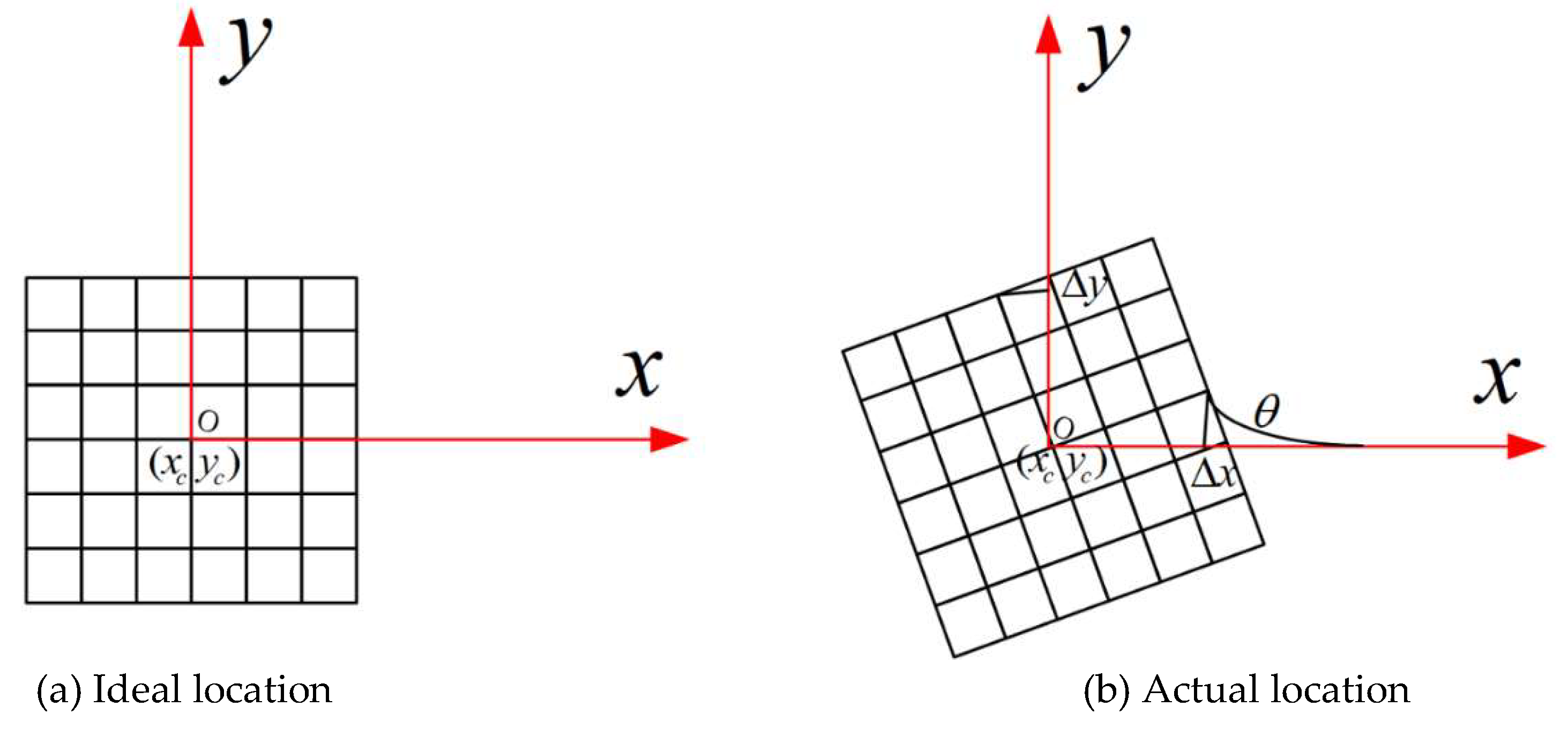
(4) Rotation error of CMOS: the installation relationship of the CMOS array in the camera coordinate system is shown in Figure 3. Assuming that the installation angle is unknown (ideally, is equal to 0), the image point deviation is as given in Equation (9).

Figure 3.
Rotation error of LJ1-01.
(5) Lens optical distortion error: it mainly includes the radial distortion and eccentricity distortion [17]. Radial distortion is caused by the surface error of the lens, which makes the image point deviate along the radial direction. According to the theory of optical design [18,19], the radial distortion can be expressed by the odd polynomial shown in Equation (10).
The image point offset caused by radial distortion is as follows:
where .
Eccentricity distortion causes the image point to deviate from the ideal position, and the eccentricity distortion can be expressed as follows:
The displacement of image points, caused by the eccentricity distortion, is as follows:
From the above modeling analysis, it can be seen that the focal length error, rotation error, and size error of the CMOS detector exhibit a strong correlation and should be considered in a unified manner. To avoid excessive parameterization of the lens distortion parameters leading to a reduction in the accuracy of the interior orientation element solution, only are solved for radial distortion and are solved for eccentricity distortion. Therefore, the integrated offset of the image points caused by the interior orientation elements is as follows:
Finally, on the basis of external calibration, Equation (14) is transformed into a linear equation for solving variables , , , , , , , .
3. Results and Discussion
3.1. Study Areas and Data Sources
The nighttime light imagery of LJ1-01 has a width of 264 km × 264 km. China has not been able to cover such a wide geometric calibration field until now. Considering that the resolution of the LJ1-01 nighttime light imagery is only 129 m, the globally publicized 15 m resolution Landsat digital orthophoto (DOM) and 90 m SRTM-DEM can be used as control data. Therefore, the LJ1-01 nighttime light imagery of the area in England on 28 June 2018, and the corresponding LandSat digital orthophotos (DOM) and SRTM were collected as control data. The DOM/DEM in the England region was collected in 2013. The DOM resolution is 14.25 m, the plane accuracy is approximately 12 m [20], the DEM resolution is 90 m and the elevation accuracy is approximately 16 m [21]. Figure 4 shows the calibration data and control data thumbnails.
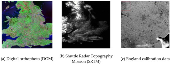
Figure 4.
England regional control and calibration data.
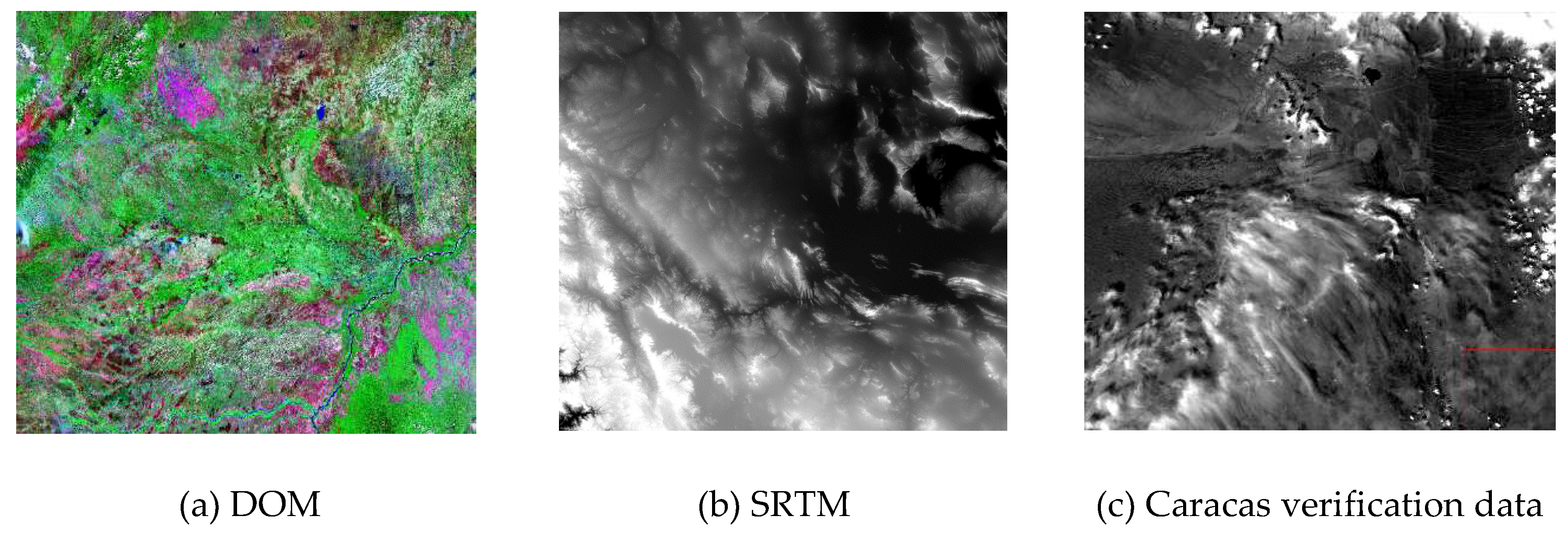
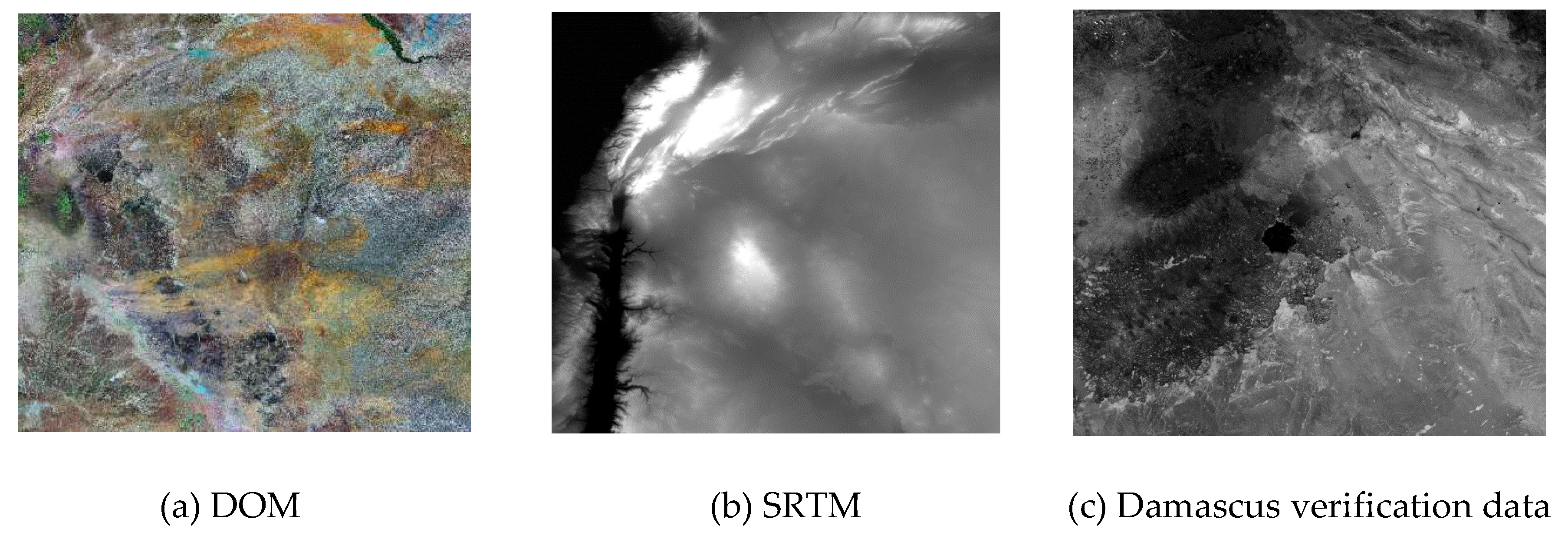
To verify the absolute positioning accuracy after geometric calibration, the uncontrolled positioning accuracy of the 44-scene data from June 2018 to August 2018 was estimated. To determine the relative positioning accuracy of the image after calibration, the images of the Torreon region of Mexico, the Caracas region of Venezuela and the Damascus area of the LJ1-01 daytime imagery were collected, and the data of the Landsat and SRTM were collected. The verification data and control data thumbnails are shown in Figure 5, Figure 6, and Figure 7. The night-light images of the Shanghai area and the Korean area were also collected. For addressing the problem of no high-precision nightlight control reference, the registration of multi-temporal images was used to evaluate the relative positioning accuracy of the image. The verification data thumbnail is shown in Figure 8. The specific imaging information of the experimental data is presented in Table 3.
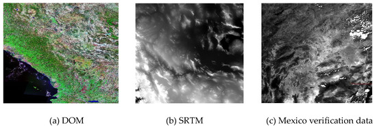
Figure 5.
Mexico Torreon regional control and verification data.
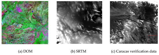
Figure 6.
Caracas regional control and verification data.

Figure 7.
Damascus regional control and validation data.
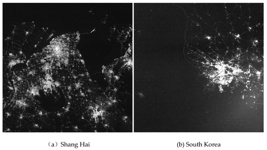
Figure 8.
Thumbnails for relative positioning accuracy verification.
Table 3.
Imaging information of experimental data.
3.2. Results of Geometric Calibration
The high-precision automatic matching algorithm [22] was adopted to match the GCPs from the calibrated scene image and the DOM of England region; 22,528 GCPs were matched and evenly distributed. The calibration accuracy is shown in Table 4.
Table 4.
Calibration accuracy.
Because the external calibration mainly eliminates the system errors of satellite attitude and orbit measurement and the camera installation system errors [14], it cannot eliminate the internal orientation element errors and the random dynamic errors of the external orientation elements [23,24]. Therefore, after external calibration, the residual positioning errors mainly reflect the internal orientation element errors (camera distortion, etc.) and the random dynamic errors of the external orientation elements; the internal calibration eliminates the internal orientation element errors further on the basis of the external calibration, and thus, the positioning error after internal calibration mainly reflects the random dynamic error of the external orientation elements. In Figure 9, the positioning error (including along-track error and vertical-track error) varies with image x and y, respectively. Although the LJ1-01 includes a CMOS array, its interior functions as a time-sharing exposure mode of the rolling shutter, which is similar to in the linear array push-broom mode. Therefore, the random dynamic errors of exterior orientation elements can be reflected by the change in y.
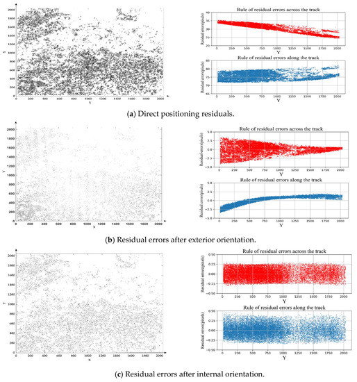
Figure 9.
Residual errors law of calibration scene.
Figure 9a shows the accuracy of the direct positioning of laboratory measurement parameters; it can be seen that geometric parameters such as those pertaining to the camera installation change significantly during the launching process, and the positioning error becomes obviously systematic. Figure 9b shows the positioning residual errors after solving the offset matrix and eliminating the errors of exterior orientation elements; we can see that some systematic errors still exist, which can be directly reflected as the errors of interior orientation elements. The maximum error of interior orientation elements of LJ1-01 can reach approximately 4 pixels. Figure 9c illustrates the positioning residual errors after solving the interior orientation elements; the overall distribution of the residuals after internal calibration is more random; the system error is eliminated thoroughly and the overall accuracy reaches 0.20 pixels. Because the single frame imaging time is only approximately 0.1 s, and the image attitude download frequency is only 1 Hz, the measurement error of the attitude and orbit in a short time (0.1 s vs. 1 s) is mainly shown as system error, and the internal calibration accuracy is mainly limited by the attitude stability. Because the attitude stability is difficult to be modeled strictly, the maximum impact on geometric positioning can be simplified as , where H is the satellite elevation, is the attitude stability, and is the attitude download frequency. The attitude stability of LJ1-01 is approximately 0.004°/s, that is, the maximum impact of attitude stability is not more than 0.3 pixels, which is basically equivalent to the accuracy of internal calibration in the Table 4.
3.3. Verification of Absolute Positioning Accuracy
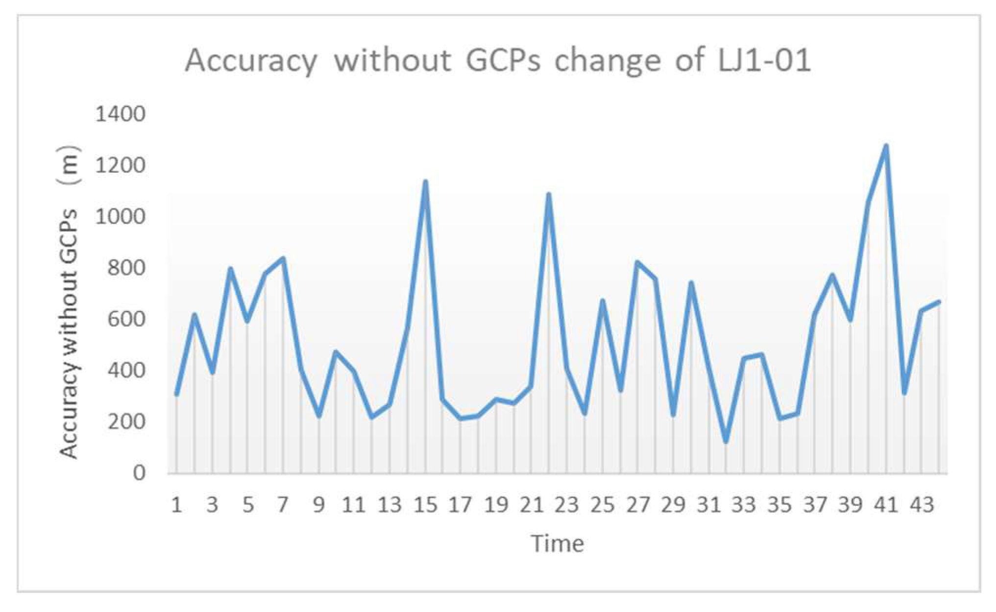
The absolute positioning accuracy in this paper refers to the distance difference between the coordinates of the ground points calculated by the rigorous geometric model and the actual ground points without relying on the ground control points. The calibration parameters of the daytime calibration scene are used for the production of nightlight data. In this study, the June, July, and August feature-identifiable nightlight images (such as roads and buildings) were selected for luminous image compensation accuracy verification without the GCPs. Using Google Earth as the reference data, the orientation accuracy without the GCPs was evaluated by manually selecting the geometric control points of the corresponding positions on Google Earth, with a selection error of approximately 1 pixel (see Figure 10 below). Finally, a total of 44-track nighttime images were recorded statistically for 31 days, and the geometric accuracy without the GCPs was better than 650 m (1σ). The specific statistical results are presented in Figure 11 and Table 5 below.
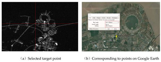
Figure 10.
Examples of uncontrolled orientation accuracy assessment.
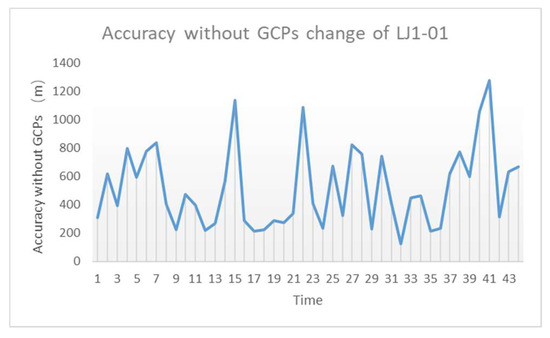
Figure 11.
Accuracy without geometric control points (GCPs) change in June–August.
Table 5.
Accuracy of statistics without GCPs of LJ1-01 in June–August.
Geometric positioning accuracy without the GCPs is mainly limited by random errors of attitude and orbit measurement and structural stability errors. From Table 1, it can be seen that the orbit height of LJ1-01 is 645 km, the orbit measurement error is approximately 10 m, and the attitude measurement error is 0.05°. Using the method defined in reference [25], the impact of attitude random errors on uncontrolled geometric positioning can be simplified as , where H is the satellite elevation and is the attitude accuracy. As shown in Table 1, the attitude accuracy of LJ1-01 is approximately 0.05°, that is, the impact of attitude random errors is approximately 562.87 m. Considering the 10-m random error of the orbit, the comprehensive effect of the random error of the attitude and orbit on uncontrolled geometric positioning is approximately 562.96 m. Compared with the statistical accuracy of the actual geometric positioning without the GCPs, the random error introduced by the structural stability of LJ1-01 is smaller, less than 1 pixel. Therefore, the absolute geometric positioning accuracy without the GCPs after calibration is in line with the theoretical design accuracy of LJ1-01.
3.4. Verification of Relative Positioning Accuracy
Relative positioning accuracy refers to the positioning accuracy relative to a certain reference. This paper is mainly used to evaluate the internal accuracy of the image.
3.4.1. Verification of Exterior Orientation Accuracy
To fully verify the calibration accuracy of the daytime calibration scene, three groups of data are selected to fully ensure the accuracy and validity of the calibration parameters. Similarly, using the automatic matching algorithm, 54,963 control points, 37,527 control points, and 53,122 control points were obtained from the verification scene images and the corresponding DOMs of Torreon, Caracas, and Damascus, respectively. The geometric control points were evenly distributed. The verification accuracies of Mexico, Caracas, and Damascus are listed in Table 6.
Table 6.
Accuracy of verification scenery.
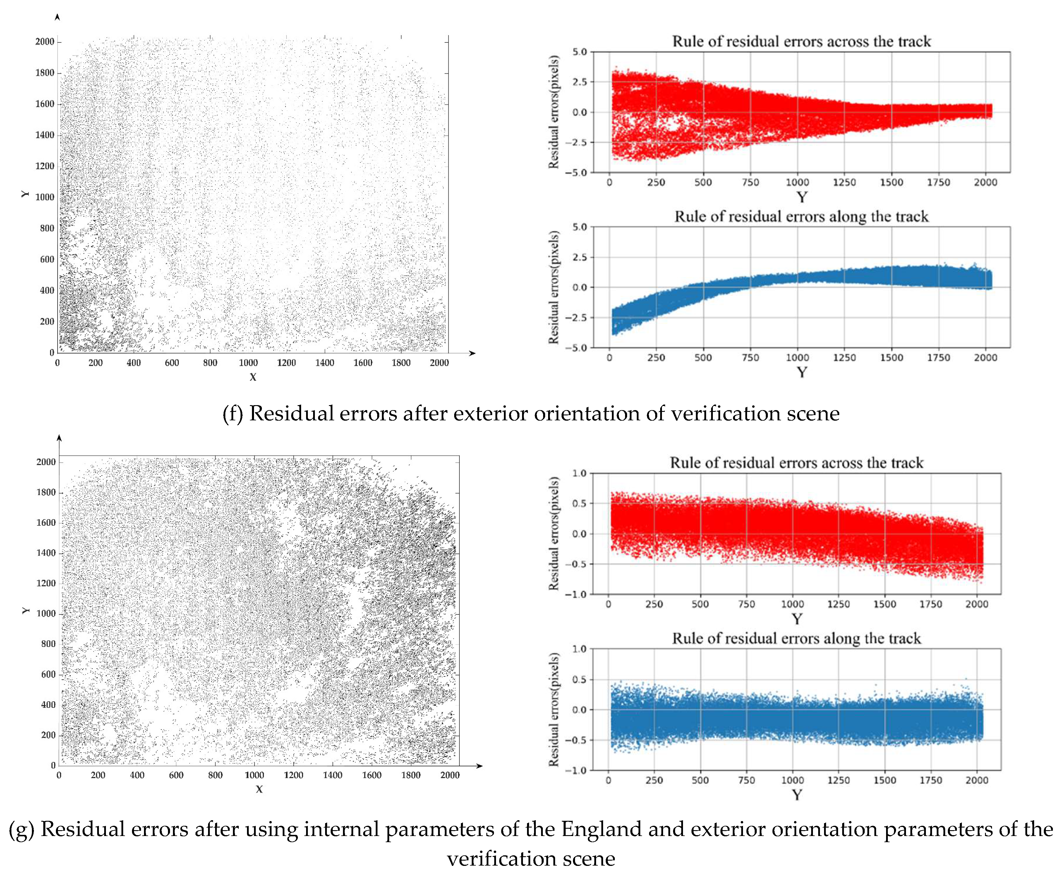
The Damascus residual diagram is presented. Figure 12d shows the geometric positioning accuracy of direct positioning by using the parameters measured in the laboratory; (e) shows the geometric positioning accuracy of using the internal and external calibration parameters of the England calibration scene; (f) shows the geometric positioning accuracy of the control points obtained from the verification scene to solve the offset matrix; (g) pertains to the geometric positioning accuracy after the offset matrix is solved using the internal calibration parameters of the calibration scene. Compared with that presented in (d) and (e), the accuracy without the GCPs was significantly improved after compensation with the England geometric calibration parameters, indicating that the England calibration parameters could eliminate systematic errors such as those concerning the satellite attitude, orbit measurement, and sensor installation. The accuracy of positioning without the use of the geometric control points after calibration was better than 5 pixels, which is equivalent to the theoretical position accuracy without the geometric control points of LJ1-01. Compared with those shown in (f) and (g), the calibration parameters in England could eliminate the error of the internal orientation elements introduced by the camera distortion and rolling shutter imaging. As described in Section 3.2, the orientation accuracy is mainly limited by the attitude stability. The accuracy when using the geometric control points improved from the maximum of 4 pixels to 0.3 pixels, which shows that the calibration parameters of England have higher accuracy and effectively eliminate the error caused by the distortion of the internal orientation elements and roll shutter imaging.
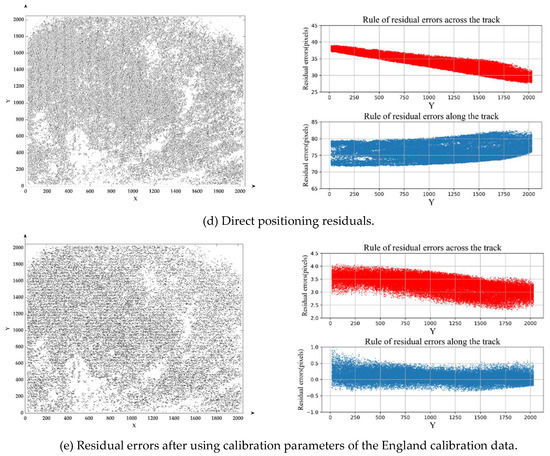

Figure 12.
Residual errors law of verification scene.
3.4.2. Multi-Time Phase Registration Accuracy Verification
The relative positioning accuracy of the image was consistent with the geometric positioning accuracy of the same image point of the single-scene image or the multi-temporal image with the same name point [26]. The business model of the LJ1-01 is the night-light mode, and the relative positioning accuracy verification of the night-light image after the calibration is particularly important. However, considering the lack of high-precision luminous image geometric reference, the registration accuracy of multi-temporal luminous images can be used to evaluate the relative positioning accuracy. The assessment method is as follows:
Collect multi-temporal luminous images of small intersection angles if two of the scene images are A and B. Using the rigorous geometric imaging model after the calibration to generate Rational Function Model(RFM) models of images A and B,
- (1)
- Match the same point from images A and B; calculate the ground coordinate corresponding to by using the RPC model of image A and SRTM; and calculate the image coordinate corresponding to by using the RPC model of image B.
- (2)
- Solve the affine model between and .
- (3)
- Using 1–3 to establish the point-to-point mapping relationship between the images A and B, resample image B based on image A. Realizing the registration of images A and B, and evaluate the registration accuracy.
It is evident that the affine model cannot represent high-order distortion of the lens. If high-order distortion is still present after the calibration, accurate registration cannot be achieved through steps 1–4, and the notable registration error will remain.
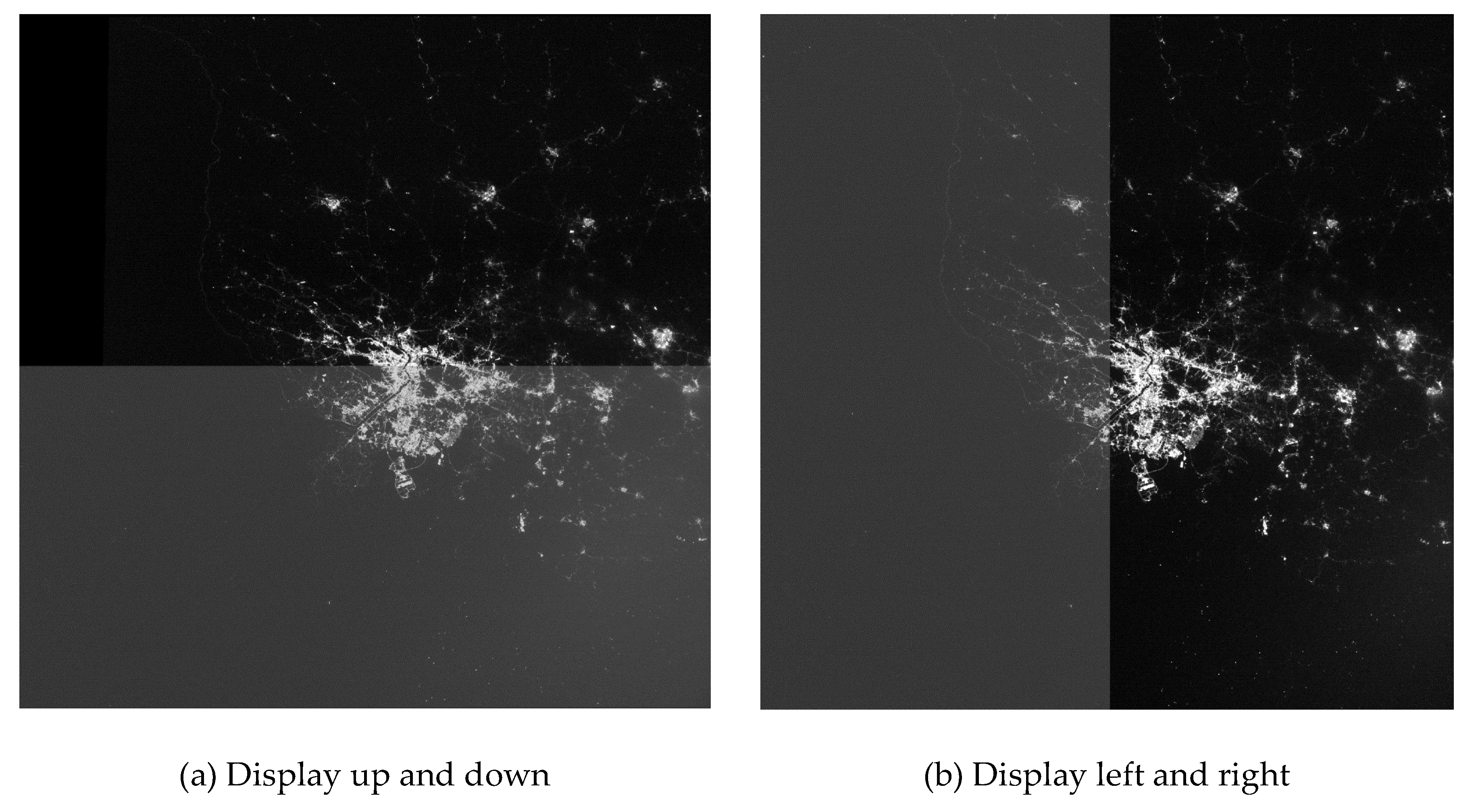
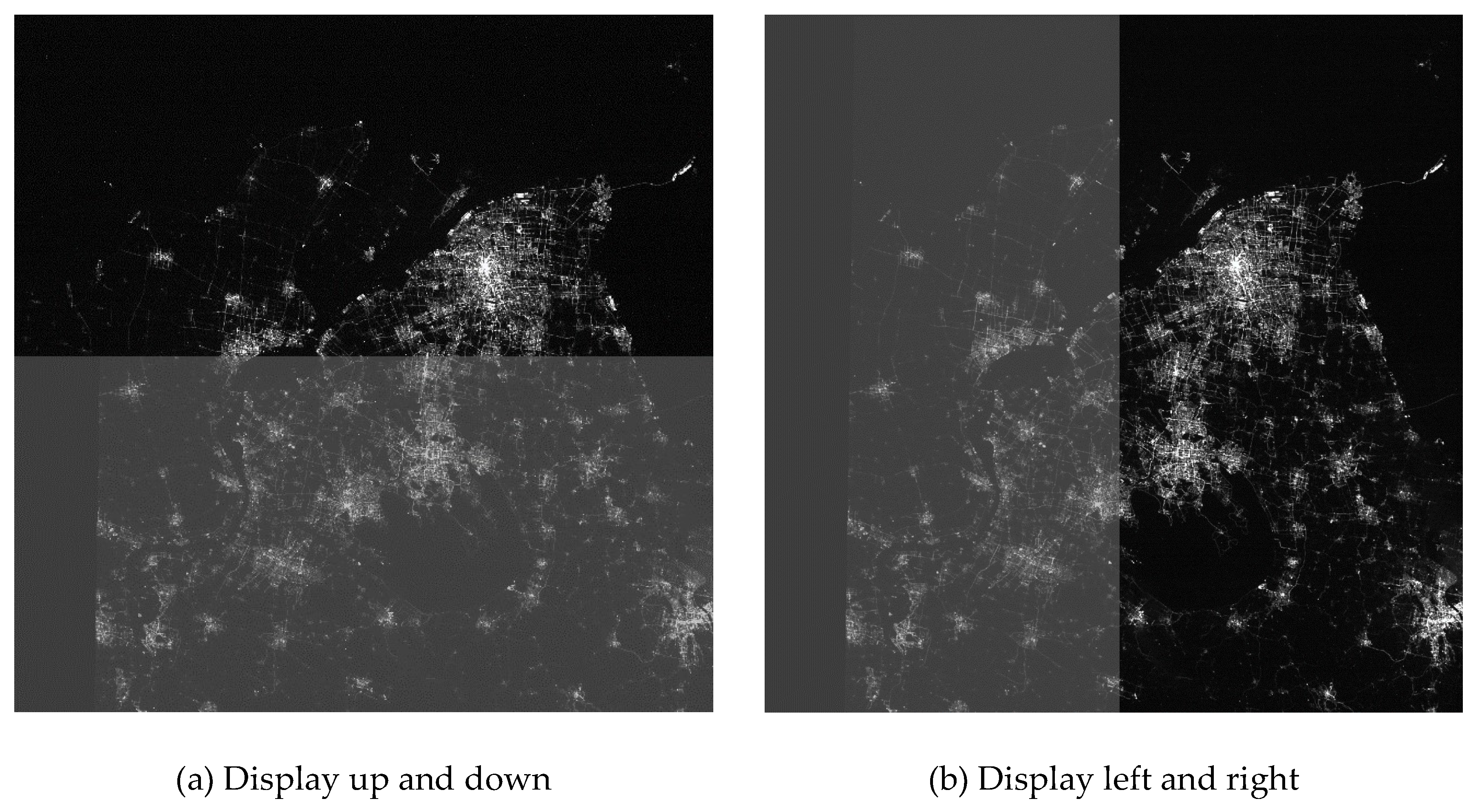
Night-light image data with a 27-day interval between two tracks were collected, as shown in Figure 8 and Table 3. Using the same set of calibration compensation parameters (i.e., England calibration compensation parameters), steps 1–4 were implemented to complete the image registration. The accuracies of Shanghai and Korea night-light image adjustment are presented in Table 7. As mentioned in Section 3.2, the orientation accuracy is mainly limited by the attitude stability. The two-track image adjustment accuracy is better than 0.4 pixels, and the maximum error is approximately 1 pixel. Finally, through step 4 of frame-by-frame re-sampling, the curtain display after resampling, as shown in Figure 13 and Figure 14, shows that the resampling images can achieve point-to-point correspondence, indicating that the geometric calibration parameters during the day can also compensate for the night image; moreover, the internal accuracy of the image is not lost, and the accuracy is approximately 0.3 pixels.
Table 7.
Accuracy of multi-temporal registration.

Figure 13.
Korea shutter display after multi-temporal registration.
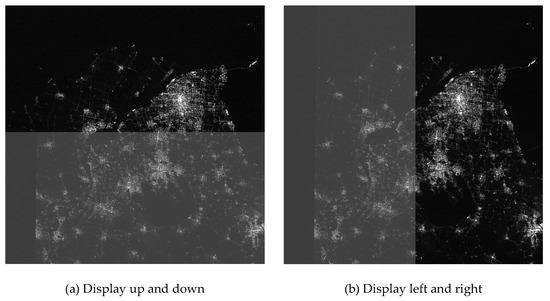
Figure 14.
Shanghai shutter display after multi-temporal registration.
4. Conclusions
On-orbit geometric calibration is particularly important to ensure the application of follow-up night-light images of LJ1-01. This paper introduces the on-orbit geometric calibration model of LJ1-01 in detail. Aiming at the difficulty of on-orbit geometric calibration of LJ1-01 night-light remote-sensing CMOS rolling shutter sensor without night-light calibration field, an on-orbit calibration scheme of "day calibration + night compensation" was proposed using LJ1-01 night-light CMOS rolling shutter sensor with daytime imaging ability. According to the dynamic imaging principle of the rolling shutter, a rigorous geometric imaging model of time-sharing exposure of the rolling shutter of LJ1-01 was constructed, and the effective compensation of daytime calibration parameters for night-light images were obtained. Experiments showed that the geometric calibration parameters of LJ1-01 during the day could compensate for the night images. Finally, the positioning accuracy with the GCPs of LJ1-01 night-light remote-sensing data was better than 0.3 pixels, and the geometric positioning accuracy without the GCPs was better than 650 m, which satisfies the requirement of subsequent applications.
Author Contributions
Y.J. and J.W. conceived and designed the experiments; J.W. performed the experiments; G.Z., P.Z., Y.Z. and Y.X. analyzed the data; J.W. wrote the paper; and all authors edited the paper.
Funding
This research was funded by the Key Research and Development Program of the Ministry of Science and Technology, grant number 2016YFB0500801; the National Natural Science Foundation of China, grant numbers 91538106, 41501503, 41601490, and 41501383.
Acknowledgments
We give thanks to the research team at Wuhan University for freely providing LuoJia1-01 nighttime light imagery. Furthermore, the authors would like to thank the reviewers for their helpful comments.
Conflicts of Interest
The authors declare no conflict of interest. The funding sponsors had no role in the design of the study; in the collection, analyses, or interpretation of data; in the writing of the manuscript; or in the decision to publish the results.
References
- Li, X.; Zhao, L.; Li, D.; Xu, H. Mapping Urban Extent Using Luojia 1-01 Nighttime Light Imagery. Sensors 2018, 18, 3665. [Google Scholar] [CrossRef] [PubMed]
- Jiang, W.; He, G.; Long, T.; Guo, H.; Yin, R.; Leng, W.; Liu, H.; Wang, G. Potentiality of Using Luojia 1-01 Nighttime Light Imagery to Investigate Artificial Light Pollution. Sensors 2018, 18, 2900. [Google Scholar] [CrossRef] [PubMed]
- Wang, L.; Chen, R.; Li, D.; Zhang, G.; Shen, X.; Yu, B.; Wu, C.; Xie, S.; Zhang, P.; Li, M.; et al. Initial Assessment of the LEO Based Navigation Signal Augmentation System from Luojia-1A Satellite. Sensors 2018, 18, 3919. [Google Scholar] [CrossRef]
- LI, D.; LI, X. An Overview on Data Mining of Nighttime Light Remote Sensing. Acta Geod. Cartogr. Sin. 2015, 44, 591–601. [Google Scholar]
- El Gamal, A.; Eltoukhy, H. CMOS image sensors. IEEE Circuits Devices Mag. 2005, 21, 6–20. [Google Scholar] [CrossRef]
- Sun, Y.; Liu, G.; Sun, Y. An Affine Motion Model for Removing Rolling Shutter Distortions. IEEE Signal Process. Lett. 2016, 23, 1250–1254. [Google Scholar] [CrossRef]
- Thanh-Tin, N.; Lhuillier, M. Self-calibration of omnidirectional multi-cameras including synchronization and rolling shutter. Comput. Vis. Image Underst. 2017, 162, 166–184. [Google Scholar] [CrossRef]
- Meingast, M.; Geyer, C.; Sastry, S. Geometric Models of Rolling-Shutter Cameras. Comput. Sci. 2005, arXiv:cs/0503076. [Google Scholar]
- Ye, W.; Qiao, G.; Kong, F.; Guo, S.; Ma, X.; Tong, X.; Li, R. PHOTOGRAMMETRIC ACCURACY AND MODELING OF ROLLING SHUTTER CAMERAS. ISPRS J. Photogramm. Remote Sens. 2016, III-3, 139–146. [Google Scholar]
- Jiang, Y.-h.; Zhang, G.; Tang, X.-m.; Li, D.; Huang, W.-C.; Pan, H.-B. Geometric Calibration and Accuracy Assessment of ZiYuan-3 Multispectral Images. IEEE Trans. Geosci. Remote Sens. 2014, 52, 4161–4172. [Google Scholar] [CrossRef]
- Tang, X.; Zhou, P.; Zhang, G.; Wang, X.; Jiang, Y.; Guo, L.; Liu, S. Verification of ZY-3 Satellite Imagery Geometric Accuracy Without Ground Control Points. IEEE Geosci. Remote Sens. Lett. 2015, 12, 2100–2104. [Google Scholar] [CrossRef]
- Mi, W.; Cheng, Y.; Chang, X.; Jin, S.; Ying, Z. On-orbit geometric calibration and geometric quality assessment for the high-resolution geostationary optical satellite GaoFen4. ISPRS J. Photogramm. Remote Sens. 2017, 125, 63–77. [Google Scholar]
- Zhang, G.; Xu, K.; Huang, W. Auto-calibration of GF-1 WFV images using flat terrain. ISPRS J. Photogramm. Remote Sens. 2017, 134, 59–69. [Google Scholar] [CrossRef]
- Jiang, Y.-H.; Zhang, G.; Chen, P.; Li, D.-R.; Tang, X.-M.; Huang, W.-C. Systematic Error Compensation Based on a Rational Function Model for Ziyuan1-02C. IEEE Trans. Geosci. Remote Sens. 2015, 53, 3985–3995. [Google Scholar] [CrossRef]
- Radhadevi, P.V.; Müller, R.; D’Angelo, P.; Reinartz, P. In-flight Geometric Calibration and Orientation of ALOS/PRISM Imagery with a Generic Sensor Model. Photogramm. Eng. Remote Sens. 2011, 77, 531–538. [Google Scholar] [CrossRef]
- Bouillon, A.; Breton, E.; Lussy, F.D.; Gachet, R. SPOT5 HRG and HRS first in-flight geometric quality results. In Proceedings of the International Symposium on Remote Sensing, Crete, Greece, 23–27 September 2002; pp. 212–223. [Google Scholar]
- Fryer, J.G.; Brown, D.C. Lens distortion for close-range photogrammetry. Photogramm. Eng. Remote Sens. 1986, 52, 51–58. [Google Scholar]
- Kong, B. A Simple and Precise Method for Radial Distortion Calibration. J. Image Graph. 2004, 9. [Google Scholar] [CrossRef]
- Fraser, C.S. Digital camera self-calibration. Isprs J. Photogramm. Remote Sens. 1997, 52, 149–159. [Google Scholar] [CrossRef]
- Landsat Data Access|Landsat Missions. Available online: https://landsat.usgs.gov/landsat-data-access (accessed on 16 December 2018).
- CGIAR-CSI SRTM—SRTM 90m DEM Digital Elevation Database. Available online: http://srtm.csi.cgiar.org/ (accessed on 16 December 2018).
- Leprince, S.; Barbot, S.; Ayoub, F.; Avouac, J.-P. Automatic and precise orthorectification, coregistration, and subpixel correlation of satellite images, application to ground deformation measurements. IEEE Trans. Geosci. Remote Sens. 2007, 45, 1529–1558. [Google Scholar] [CrossRef]
- Jiang, Y.; Cui, Z.; Zhang, G.; Wang, J.; Xu, M.; Zhao, Y.; Xu, Y. CCD distortion calibration without accurate ground control data for pushbroom satellites. Isprs J. Photogramm. Remote Sens. 2018, 142, 21–26. [Google Scholar] [CrossRef]
- Jiang, Y.-H.; Zhang, G.; Tang, X.; Li, D.; Huang, W.-C. Detection and Correction of Relative Attitude Errors for ZY1-02C. IEEE Trans. Geosci. Remote Sens. 2014, 52, 7674–7683. [Google Scholar] [CrossRef]
- Xinming, T.; Guo, Z.; Huang, W.; Jiang, W.; Wu, X.; Fen, H. Plane and Stereo Precision Prediction Method for LEO Satellites. Available online: https://patents.google.com/patent/CN103868531A/zh (accessed on 16 December 2018).
- Wang, J.; Wang, R.; Xin, H.U. Discussion on Evaluation of Satellite Imagery Location Accuracy. Spacecr. Recov. Remote Sens. 2017, 38, 1–5. [Google Scholar]


© 2019 by the authors. Licensee MDPI, Basel, Switzerland. This article is an open access article distributed under the terms and conditions of the Creative Commons Attribution (CC BY) license (http://creativecommons.org/licenses/by/4.0/).