A Generic Approach toward Indoor Navigation and Pathfinding with Robust Marker Tracking


Abstract
1. Introduction
- (1)
- Accuracy and continuity: The accuracy and continuity of locations are important, especially for visually impaired people. For a real-time guidance, a localization accuracy of about two meters is desired. A higher localization error could mislead a user on a wrong path or cause collision in the environment.
- (2)
- Scaling and extendibility: A number of previous methods are available for single story and 2D plan environments [7]. However, most of the buildings such as shopping malls, universities, and hospitals have multistory buildings. User localization in such multi-story building is further challenging, for example, localization across floors and during floor transition. Similarly, extending an existing indoor system in a building to the new areas such as adding a new floor or installing new rooms is further challenging, where existing methods often failed.
- (3)
- Signal strength: Some of the state-of-the-art methods are concerned with signal processing. These methods suffer from signal issues, for example some devices may receive weak signals than others.
- (4)
- Computational cost and efficiency: The computational cost is another challenging issue, especial for large-scale buildings. Efficient methods are required to accurately localize a user in real time.
- (5)
- Motion recognition: To recognize a user from the walking style or to detect users’ steps during walking is also a challenging issue. It helps in accurate localization and time calculation to reach a destination. However, incase if the internal sensors missed the steps, it may cause a noticeable localization error.
- (6)
- Delay Detection: The delay in signal is also a challenging issue in indoor navigation. The delayed data may cause to mislead a user, particularly at decision points such as corridor intersections, stairs, and entrances.
- We proposed a smartphone-based indoor navigation system with automatic path generation and user guidance in audio/textual form.
- The proposed system is efficient, low-cost, accurate, easy-to-install, and easy-to-use.
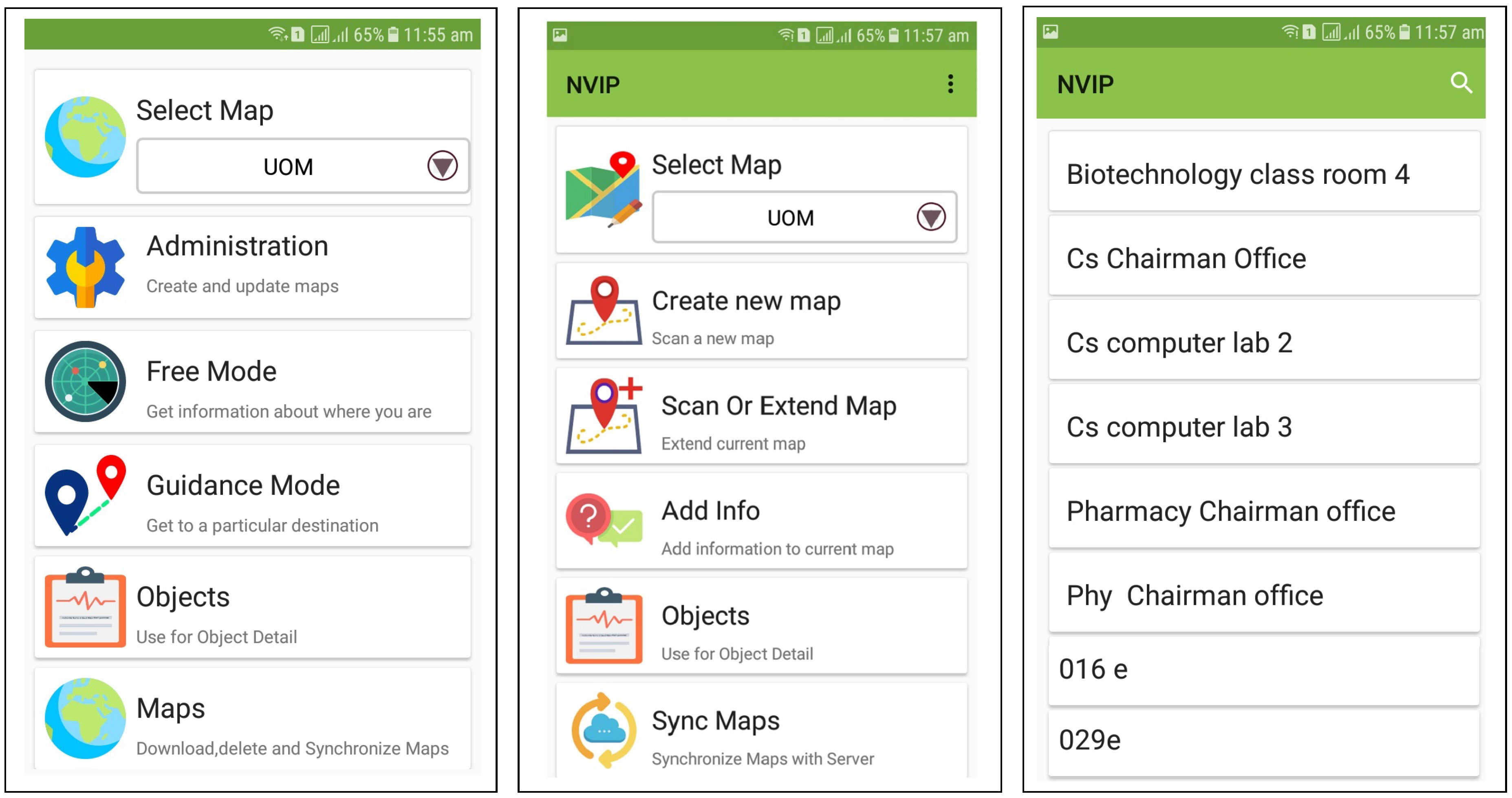
- The system is implemented as an extendable android application, which allows the building administrator to manage floor plans, and add or delete new nodes (Fiducial markers) with corresponding audio/textual information. It is generic and can be implemented in any arbitrary indoor environment.
- We evaluated the proposed system with users using four different paths of navigation in an indoor environment, and found it accurate and efficient.
2. Preliminaries and Definitions
2.1. Augmented Reality
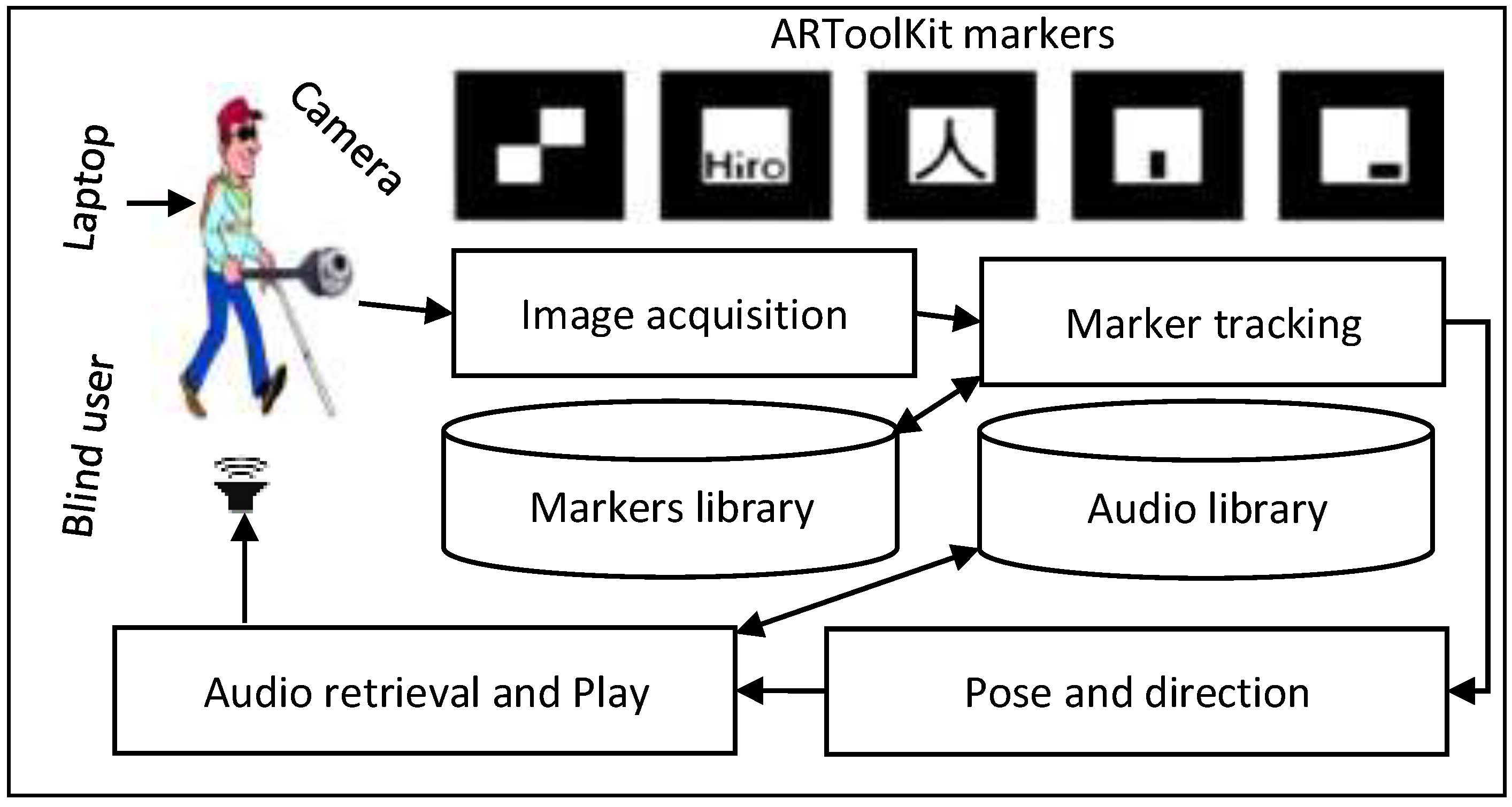
2.2. Fiducial Markers and ARToolKit
3. Related Work
3.1. Wireless Networking for Indoor Navigation
3.2. Computer Vision Applications in Indoor Navigation
3.3. Smartphone-Based Indoor Navigation
3.4. Problems with State-of-the-Art
4. Our Method
- We designed a low-cost navigation system that uses simple fiducial markers. The markers are printed on a plain paper, and placed on the ceilings of the building near different places such as offices, stairs, rooms, and corridors (see Figure 4).
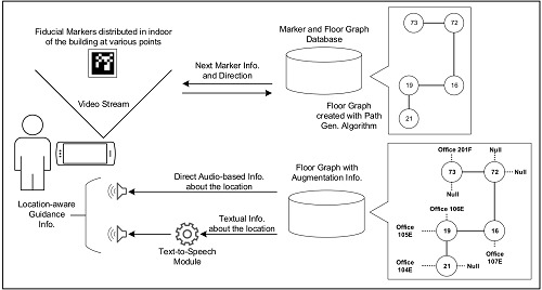
- The system automatically generates path by detecting and connecting the fiducial markers with the help of a smartphone camera and creates a graph in the phone by connecting the markers.
- The system has audio/textual information played/displayed to guide the user upon the recognition of each marker.
- The user is guided toward a given destination by following a shortest path inside a single or multi-floor building.
- The system is dynamically extendable. It provides a way to edit an already generated path, and to extend it for incorporating newly deployed markers in the building.
4.1. Algorithm Overview and Marker Placement
4.2. Path Generation and Augmentation
- Switch()Case: : “Direct straight”Case: : “Direct right”Case: : “Direct back”Case: : “Direct left”
- End.
4.3. Path Extension
4.4. User Guidance
5. Experimental Study and Results
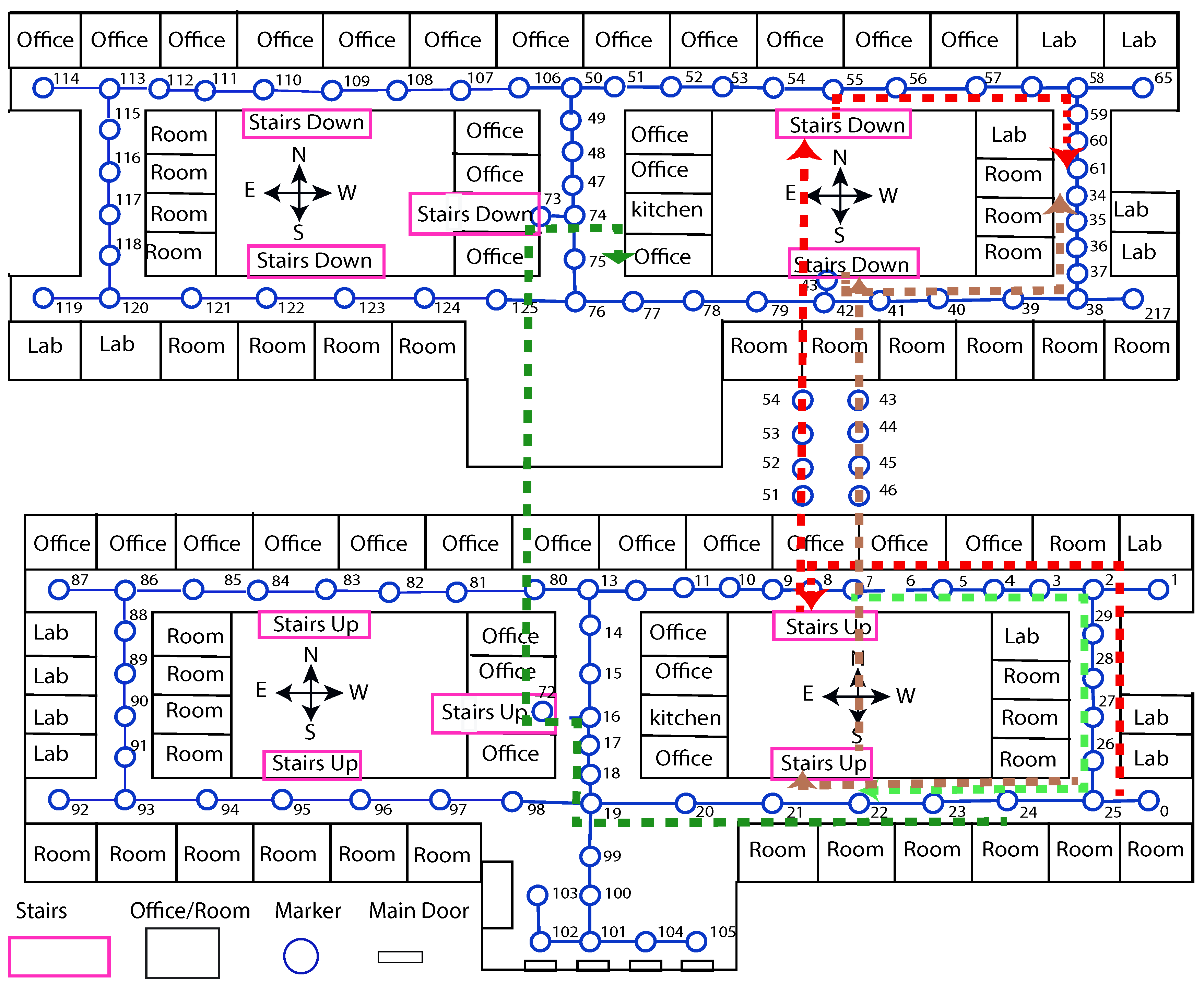
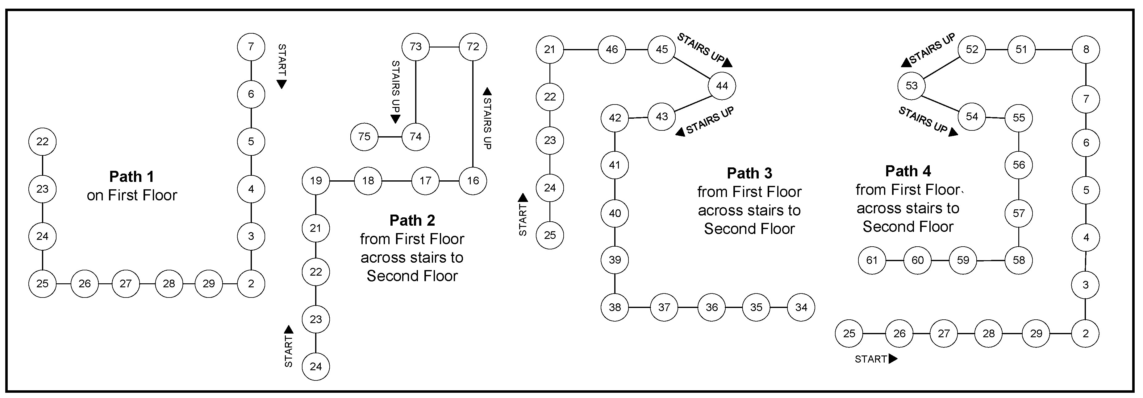
- Path-1:
- This path goes across the corridor of first floor from one of the office (ID: 7) up to a classroom (ID: 22) on the same floor.
- Path-2:
- It starts at a classroom (ID: 24) on the first floor and reaches an office (ID: 75) on the second floor across stairs (ID: 72-73).
- Path-3:
- It starts at a classroom (ID: 25) on the first floor and follows to a classroom (ID: 34) on the second floor across stairs (ID: 46-42)
- Path-4:
- It starts at a classroom (ID: 25) to a hall (ID: 75) on the second floor across stairs (ID: 51-55).
5.1. Guidance Test
5.2. Evaluation and Results
- Q. 1:
- How much do you rate the system reliability?
- Q. 2:
- How much are you satisfied with the guidance information to get your destination?
- Q. 3:
- How much do you rate that the proposed system is easy to use?
- Q. 4:
- How much do you rate the response time?
- Q. 5:
- How much do you feel free while navigating with the proposed system?
6. Discussion and Conclusions
6.1. Limitations and Future Work
- The marker placement is still difficult and it may affect the beauty of the building. To address this issue we are planning to use hidden markers or tracking natural images.
- In our experiments, we did not find visually impaired participant. Furthermore, we did not implement any existing system for possible comparison of the results.
- One limitation of our work is that it directs the users in four directions including forward, backward, left, right. It requires a structured indoor environment. The marker placement is required to be parallel to the corresponding paths (see Figure 6). In future, we are planning to solve this issue. In addition, we are also planning to use the concept of hidden markers.
6.2. Conclusions
Author Contributions
Funding
Acknowledgments
Conflicts of Interest
Abbreviations
| UWB | Ultra wideband |
| RFID | Radio-frequency identification |
| IR | Infrared |
| AR | Augmented Reality |
| RSS | Received signal strength |
| VLC | visible light communications |
| OOK | On-and-off keying |
| LED | Light emitting diode |
| GPS | Global positioning system |
| CDNN | Cascaded deep neural network |
| SUS | System usability scale |
| NFC | Near field communication |
References
- Díaz-Vilariño, L.; Boguslawski, P.; Khoshelham, K.; Lorenzo, H. Obstacle-Aware Indoor Pathfinding Using Point Clouds. ISPRS Int. J. Geo-Inf. 2019, 8, 233. [Google Scholar] [CrossRef]
- Ganz, A.; Schafer, J.; Gandhi, S.; Puleo, E.; Wilson, C.; Robertson, M. PERCEPT Indoor Navigation System for the Blind and Visually Impaired: Architecture and Experimentation. Int. J. Telemed. Appl. 2012, 2012, 19:1–19:12. [Google Scholar] [CrossRef] [PubMed]
- Khoshelham, K.; Zlatanova, S. Sensors for Indoor Mapping and Navigation. Sensors 2016, 16, 655. [Google Scholar] [CrossRef] [PubMed]
- Wang, Y.T.; Peng, C.C.; Ravankar, A.A.; Ravankar, A. A Single LiDAR-Based Feature Fusion Indoor Localization Algorithm. Sensors 2018, 18, 1294. [Google Scholar] [CrossRef]
- Winter, S.; Tomko, M.; Vasardani, M.; Richter, K.F.; Khoshelham, K.; Kalantari, M. Infrastructure-Independent Indoor Localization and Navigation. ACM Comput. Surv. 2019, 52, 61:1–61:24. [Google Scholar] [CrossRef]
- Murata, M.; Ahmetovic, D.; Sato, D.; Takagi, H.; Kitani, K.M.; Asakawa, C. Smartphone-based localization for blind navigation in building-scale indoor environments. Pervasive Mob. Comput. 2019, 57, 14–32. [Google Scholar] [CrossRef]
- Lymberopoulos, D.; Liu, J.; Yang, X.; Choudhury, R.R.; Handziski, V.; Sen, S. A Realistic Evaluation and Comparison of Indoor Location Technologies: Experiences and Lessons Learned. In Proceedings of the 14th International Conference on Information Processing in Sensor Networks IPSN ’15, Seattle, WA, USA, 14–16 April 2015; ACM: New York, NY, USA, 2015; pp. 178–189. [Google Scholar]
- Liu, H.; Darabi, H.; Banerjee, P.; Liu, J. Survey of Wireless Indoor Positioning Techniques and Systems. IEEE Trans. Syst. Man Cybern. Part C (Appl. Rev.) 2007, 37, 1067–1080. [Google Scholar] [CrossRef]
- Abbott, E.; Powell, D. Land-vehicle navigation using GPS. Proc. IEEE 1999, 87, 145–162. [Google Scholar] [CrossRef]
- Hassan, M.R.; Haque, M.S.M.; Hossain, M.I.; Hassan, M.M.; Alelaiwi, A. A novel cascaded deep neural network for analyzing smart phone data for indoor localization. Futur. Gener. Comput. Syst. 2019, 101, 760–769. [Google Scholar] [CrossRef]
- Kato, H.; Billinghurst, M. Marker Tracking and HMD Calibration for a Video-based Augmented Reality Conferencing System. In Proceedings of the 2nd IEEE and ACM International Workshop on Augmented Reality (IWAR ’99), San Francisco, CA, USA, 20–21 October 1999; pp. 85–94. [Google Scholar]
- Zeb, A.; Ullah, S.; Rabbi, I. Indoor vision-based auditory assistance for blind people in semi controlled environments. In Proceedings of the 2014 4th International Conference on Image Processing Theory, Tools and Applications (IPTA), Paris, France, 14–17 October 2014; pp. 1–6. [Google Scholar]
- Brooke, J. SUS: A quick and dirty usability scale. In Usability Evaluation in Industry; Jordan, P.W., Thomas, B., Eds.; Taylor and Francis: London, UK, 1996; pp. 189–194. [Google Scholar]
- Aloor, J.J.; Sahana, P.S.; Seethal, S.; Thomas, S.; Pillai, M.T.R. Design of VR headset using augmented reality. In Proceedings of the 2016 International Conference on Electrical, Electronics, and Optimization Techniques (ICEEOT), Chennai, India, 3–5 March 2016; pp. 3540–3544. [Google Scholar]
- Fiala, M. ARTag, a Fiducial marker system using digital techniques. In Proceedings of the 2005 IEEE Computer Society Conference on Computer Vision and Pattern Recognition (CVPR’05), San Diego, CA, USA, 20–25 June 2005; pp. 590–596. [Google Scholar]
- Garrido-Jurado, S.; Muñoz-Salinas, R.; Madrid-Cuevas, F.; Medina-Carnicer, R. Generation of fiducial marker dictionaries using Mixed Integer Linear Programming. Pattern Recognit. 2016, 51, 481–491. [Google Scholar] [CrossRef]
- Garrido-Jurado, S.; Muñoz-Salinas, R.; Madrid-Cuevas, F.; Marín-Jiménez, M. Automatic generation and detection of highly reliable fiducial markers under occlusion. Pattern Recognit. 2014, 47, 2280–2292. [Google Scholar] [CrossRef]
- Wagner, D.; Schmalstieg, D. ARToolKitPlus for Pose Tracking on Mobile Devices. In Proceedings of the 12th Computer Vision Winter Workshop (CVWW’07), Paris, France, 4–6 February 2007; pp. 139–146. [Google Scholar]
- Kato, H.; Billinghurst, M.; Poupyrev, I. ARToolKit Version 2.33. Available online: www.tinmith.net/lca2004/ARToolkit/ARToolKit2.33doc.pdf (accessed on 27 August 2019).
- Sun, R.; Sui, Y.; Li, R.; Shao, F. The Design of a New Marker in Augmented Reality. In Proceedings of the Int. Conf. on Economics and Finance Research, Singapore, 26–28 February 2011; pp. 129–132. [Google Scholar]
- Vriends, T.; Coroporaal, H. Evaluation of High Level Synthesis for the Implementation of Marker Detection on FPGA. Master’s Thesis, Eindhoven University of Technology, Eindhoven, The Netherlands, 2011. [Google Scholar]
- Fiala, M. Comparing ARTag and ARToolkitPlus Fiducial Marker Systems. In Proceedings of the HAVE 2005-IEEE International Workshop on Haptic Audio Visual Environments and Applications, Ottawa, ON, Canada, 1–2 October 2005; pp. 148–153. [Google Scholar]
- Fiala, M. Designing highly reliable fiducial markers. IEEE Trans. Pattern Anal. Mach. Intell. 2010, 32, 1317–1324. [Google Scholar] [CrossRef] [PubMed]
- Wu, H.; Shao, F.; Sun, R. Research of quickly identifying markers on Augmented Reality. In Proceedings of the IEEE International Conference on Advanced Management Science (ICAMS), Chengdu, China, 9–11 July 2010; pp. 671–675. [Google Scholar]
- Siltanen, S.; Teknillinen Tutkimuskeskus, V. Theory and Applications of Marker-based Augmented Reality; VTT Science: Espoo, Finland, 2012. [Google Scholar]
- Owen, C.B.; Xiao, F.; Middlin, P. What is the best fiducial? In Proceedings of the First IEEE International Augmented Reality Toolkit Workshop, Darmstadt, Germany, 29 September 2002; pp. 98–105. [Google Scholar]
- Tran, H.; Mukherji, A.; Bulusu, N.; Pandey, S.; Zhang, X. Improving Infrastructure-based Indoor Positioning Systems with Device Motion Detection. In Proceedings of the 2019 IEEE International Conference on Pervasive Computing and Communications (PerCom), Kyoto, Japan, 11–15 March 2019; pp. 176–185. [Google Scholar]
- Ghassemlooy, Z.; Arnon, S.; Uysal, M.; Xu, Z.; Cheng, J. Emerging Optical Wireless Communications-Advances and Challenges. IEEE J. Sel. Areas Commun. 2015, 33, 1738–1749. [Google Scholar] [CrossRef]
- Li, Y.; Ghassemlooy, Z.; Tang, X.; Lin, B.; Zhang, Y. A VLC Smartphone Camera Based Indoor Positioning System. IEEE Photonics Technol. Lett. 2018, 30, 1171–1174. [Google Scholar] [CrossRef]
- Barnard, M. The Global Positioning System. IEE Rev. 1992, 38, 99–103. [Google Scholar] [CrossRef][Green Version]
- Panzieri, S.; Pascucci, F.; Ulivi, G. An outdoor navigation system using GPS and inertial platform. IEEE/ASME Trans. Mechatron. 2002, 7, 134–142. [Google Scholar] [CrossRef]
- Ozdenizci, B.; Ok, K.; Coskun, V.; Aydin, M.N. Development of an Indoor Navigation System Using NFC Technology. In Proceedings of the 2011 Fourth International Conference on Information and Computing, Washington, DC, USA, 28–29 March 2011; pp. 11–14. [Google Scholar]
- Yelamarthi, K.; Haas, D.; Nielsen, D.; Mothersell, S. RFID and GPS integrated navigation system for the visually impaired. In Proceedings of the 2010 53rd IEEE International Midwest Symposium on Circuits and Systems, Seattle, WA, USA, 1–4 August 2010. [Google Scholar]
- Fallah, N.; Bekris, K.E.; Folmer, E. Indoor Human Navigation Systems: A Survey. Interact. Comput. 2013, 25, 21–33. [Google Scholar]
- Blattner, A.; Vasilev, Y.; Harriehausen-Mühlbauer, B. Mobile Indoor Navigation Assistance for Mobility Impaired People. Procedia Manuf. 2015, 3, 51–58. [Google Scholar] [CrossRef]
- Mahmood, A.; Javaid, N.; Razzaq, S. A review of wireless communications for smart grid. Renew. Sustain. Energy Rev. 2015, 41, 248–260. [Google Scholar] [CrossRef]
- Abu Doush, I.; Alshatnawi, S.; Al-Tamimi, A.K.; Alhasan, B.; Hamasha, S. ISAB: Integrated Indoor Navigation System for the Blind. Interact. Comput. 2016, 29, 181–202. [Google Scholar] [CrossRef]
- Rabbi, I.; Ullah, S. A Survey on Augmented Reality Challenges and Tracking. Acta Gr. 2013, 24, 29–46. [Google Scholar]
- Zafari, F.; Gkelias, A.; Leung, K.K. A Survey of Indoor Localization Systems and Technologies. IEEE Commun. Surv. Tutor. 2019, 21, 2568–2599. [Google Scholar] [CrossRef]
- Kasprzak, S.; Komninos, A.; Barrie, P. Feature-Based Indoor Navigation Using Augmented Reality. In Proceedings of the 2013 9th International Conference on Intelligent Environments, Athens, Greece, 18–19 July 2013; pp. 100–107. [Google Scholar]
- Xie, T.; Jiang, H.; Zhao, X.; Zhang, C. A Wi-Fi-Based Wireless Indoor Position Sensing System with Multipath Interference Mitigation. Sensors 2019, 19, 3983. [Google Scholar] [CrossRef] [PubMed]
- Mehta, P.; Kant, P.; Shah, P.; Roy, A.K. VI-Navi: A Novel Indoor Navigation System for Visually Impaired People. In Proceedings of the 12th International Conference on Computer Systems and Technologies, CompSysTech ’11, Vienna, Austria, 16–17 June 2011; pp. 365–371. [Google Scholar]
- Kjærgaard, M.B.; Blunck, H.; Godsk, T.; Toftkjær, T.; Christensen, D.L.; Grønbæk, K. Indoor Positioning Using GPS Revisited. In Pervasive Computing; Floréen, P., Krüger, A., Spasojevic, M., Eds.; Springer: Berlin/Heidelberg, Germany, 2010; pp. 38–56. [Google Scholar]
- Mulloni, A.; Seichter, H.; Schmalstieg, D. Handheld Augmented Reality Indoor Navigation with Activity-based Instructions. In Proceedings of the 13th International Conference on Human Computer Interaction with Mobile Devices and Services, Stockholm, Sweden, 30 August–2 September 2011; pp. 211–220. [Google Scholar]
- Lo, C.C.; Lin, T.C.; Wang, Y.C.; Tseng, Y.C.; Ko, L.C.; Kuo, L.C. Using Intelligent Mobile Devices for Indoor Wireless Location Tracking, Navigation, and Mobile Augmented Reality. In Proceedings of the IEEE VTS Asia Pacific Wireless Commun. Symposium (APWCS), Kaohsiung, Taiwan, 20–21 May 2010. [Google Scholar]
- Mohamed, A.; Adel Moussa, N.E.S. Map Aided Pedestrian Dead Reckoning Using Buildings Information for Indoor Navigation Applications. Positioning 2013, 4, 227–239. [Google Scholar]
- Huey, L.C.; Sebastian, P.; Drieberg, M. Augmented reality based indoor positioning navigation tool. In Proceedings of the 2011 IEEE Conference on Open Systems, Langkawi, Malaysia, 25–28 September 2011; pp. 256–260. [Google Scholar]
- Kim, J.; Jun, H. Vision-based location positioning using augmented reality for indoor navigation. IEEE Trans. Consum. Electron. 2008, 54, 954–962. [Google Scholar] [CrossRef]
- Kalkusch, M.; Lidy, T.; Knapp, N.; Reitmayr, G.; Kaufmann, H.; Schmalstieg, D. Structured visual markers for indoor pathfinding. In Proceedings of the First IEEE International Workshop Agumented Reality Toolkit, Darmstadt, Germany, 29 September 2002; pp. ART02:1–ART02:8. [Google Scholar]
- Al-Khalifa, S.; Al-Razgan, M. Ebsar: Indoor guidance for the visually impaired. Comput. Electr. Eng. 2016, 54, 26–39. [Google Scholar] [CrossRef]
- AL-Madani, B.; Orujov, F.; Maskeliunas, R.; Damaševičius, R.; Venčkauskas, A. Fuzzy Logic Type-2 Based Wireless Indoor Localization System for Navigation of Visually Impaired People in Buildings. Sensors 2019, 19, 2114. [Google Scholar] [CrossRef]
- Chandgadkar, A. An Indoor Navigation System for Smartphones; Department of Computer Science: London, UK, 2013. [Google Scholar]
- Seco, F.; Jiménez, A.R. Smartphone-Based Cooperative Indoor Localization with RFID Technology. Sensors 2018, 18, 266. [Google Scholar] [CrossRef]
- Dijkstra, E.W. A note on two problems in connexion with graphs. Numer. Math. 1959, 1, 269–271. [Google Scholar] [CrossRef]
- Khan, D.; Ullah, S.; Rabbi, I. Factors affecting the design and tracking of ARToolKit markers. Comput. Stand. Interfaces 2015, 41, 56–66. [Google Scholar] [CrossRef]
- Zhao, H.; Cheng, W.; Yang, N.; Qiu, S.; Wang, Z.; Wang, J. Smartphone-Based 3D Indoor Pedestrian Positioning through Multi-Modal Data Fusion. Sensors 2019, 19, 4554. [Google Scholar] [CrossRef] [PubMed]


| Path | Source Node: Floor (ID) | Destination Node: Floor (ID) | Total Makers | Total Distance (meter) |
|---|---|---|---|---|
| 1 | First Floor (7) | First Floor (22) | 14 | 35.0 |
| 2 | First Floor (24) | Second Floor (75) | 12 | 30.5 |
| 3 | First Floor (25) | Second Floor (34) | 18 | 39.0 |
| 4 | First Floor (25) | Second Floor (61) | 23 | 45.1 |
| Path | User | Time Taken (Second) | Miss Detections | False Detections |
|---|---|---|---|---|
| (a) Guidance along path-1 | 1 | 180 | 0 | 0 |
| 2 | 130 | 0 | 2 | |
| 3 | 120 | 0 | 0 | |
| 4 | 180 | 0 | 0 | |
| 5 | 180 | 0 | 0 | |
| 6 | 165 | 0 | 0 | |
| 7 | 128 | 0 | 0 | |
| 8 | 190 | 0 | 0 | |
| 9 | 195 | 0 | 0 | |
| 10 | 176 | 0 | 0 | |
| (b) Guidance along path-2 | 1 | 210 | 0 | 0 |
| 2 | 240 | 0 | 0 | |
| 3 | 165 | 0 | 0 | |
| 4 | 202 | 0 | 0 | |
| 5 | 180 | 0 | 0 | |
| 6 | 240 | 0 | 0 | |
| 7 | 161 | 0 | 0 | |
| 8 | 222 | 0 | 0 | |
| 9 | 178 | 0 | 0 | |
| 10 | 165 | 0 | 0 | |
| (c) Guidance along path-3 | 1 | 178 | 0 | 0 |
| 2 | 120 | 0 | 0 | |
| 3 | 140 | 0 | 0 | |
| 4 | 173 | 0 | 0 | |
| 5 | 150 | 0 | 0 | |
| 6 | 150 | 0 | 0 | |
| 7 | 153 | 0 | 0 | |
| 8 | 177 | 0 | 0 | |
| 9 | 156 | 0 | 0 | |
| 10 | 149 | 0 | 0 | |
| (d) Guidance along path-4 | 1 | 357 | 0 | 0 |
| 2 | 300 | 0 | 0 | |
| 3 | 240 | 0 | 0 | |
| 4 | 226 | 0 | 0 | |
| 5 | 285 | 0 | 0 | |
| 6 | 310 | 0 | 0 | |
| 7 | 229 | 0 | 0 | |
| 8 | 180 | 0 | 0 | |
| 9 | 279 | 0 | 0 | |
| 10 | 313 | 0 | 0 |
| Concerned Statement | Strongly Disagree | Strongly Agree | Average Score | ||||
|---|---|---|---|---|---|---|---|
| 1 | 2 | 3 | 4 | 5 | |||
| 1 | I think, I would like to use this system in any new indoor environment (if available). | 0 | 0 | 0 | 1 | 9 | 3.9 |
| 2 | I think, the system is unnecessarily complex. | 7 | 3 | 0 | 0 | 0 | 3.7 |
| 3 | I think the system is easy to use. | 0 | 0 | 1 | 1 | 8 | 3.7 |
| 4 | I think that I would need the support of a technical person to be able to use this system. | 7 | 2 | 1 | 0 | 0 | 3.6 |
| 5 | Various functions in this system were well integrated. | 0 | 0 | 0 | 5 | 5 | 3.5 |
| 6 | I found too much inconsistency in this system. | 10 | 0 | 0 | 0 | 0 | 4.0 |
| 7 | I would imagine that most people would learn to use this system very quickly. | 0 | 0 | 0 | 4 | 6 | 3.6 |
| 8 | I think the system is very difficult to use. | 8 | 2 | 0 | 0 | 0 | 3.8 |
| 9 | I felt very confident using this system | 0 | 0 | 0 | 5 | 5 | 3.5 |
| 10 | I needed to learn a lot of things before I could start navigating with this system. | 6 | 3 | 1 | 0 | 0 | 3.5 |
| Concerned Opinion | Total | Poor | Satisfactory | Good | Very Good | Excellent |
|---|---|---|---|---|---|---|
| Q.1: System reliability | 10 | 0 | 0 | 0 | 1 | 9 |
| Q.2: Satisfaction from the guidance | 10 | 0 | 0 | 1 | 2 | 7 |
| Q.3: Usability | 10 | 0 | 0 | 0 | 2 | 8 |
| Q.4: Response time | 10 | 0 | 0 | 2 | 2 | 6 |
| Q.5: Freedom in navigation | 10 | 0 | 3 | 1 | 2 | 4 |
© 2019 by the authors. Licensee MDPI, Basel, Switzerland. This article is an open access article distributed under the terms and conditions of the Creative Commons Attribution (CC BY) license (http://creativecommons.org/licenses/by/4.0/).
Share and Cite
Khan, D.; Ullah, S.; Nabi, S. A Generic Approach toward Indoor Navigation and Pathfinding with Robust Marker Tracking. Remote Sens. 2019, 11, 3052. https://doi.org/10.3390/rs11243052
Khan D, Ullah S, Nabi S. A Generic Approach toward Indoor Navigation and Pathfinding with Robust Marker Tracking. Remote Sensing. 2019; 11(24):3052. https://doi.org/10.3390/rs11243052
Chicago/Turabian StyleKhan, Dawar, Sehat Ullah, and Syed Nabi. 2019. "A Generic Approach toward Indoor Navigation and Pathfinding with Robust Marker Tracking" Remote Sensing 11, no. 24: 3052. https://doi.org/10.3390/rs11243052
APA StyleKhan, D., Ullah, S., & Nabi, S. (2019). A Generic Approach toward Indoor Navigation and Pathfinding with Robust Marker Tracking. Remote Sensing, 11(24), 3052. https://doi.org/10.3390/rs11243052