Article

Integrated Precise Orbit Determination of Multi-GNSS and Large LEO Constellations

1
School of Geodesy and Geomatics, Wuhan University, 129 Luoyu Road, Wuhan 430079, China
2
China Academy of Space Technology (Xi’an), Xi’an 710100, China
*
Author to whom correspondence should be addressed.
Remote Sens. 2019, 11(21), 2514; https://doi.org/10.3390/rs11212514
Submission received: 30 August 2019 / Revised: 10 October 2019 / Accepted: 24 October 2019 / Published: 27 October 2019

Abstract

:
Global navigation satellite system (GNSS) orbits are traditionally determined by observation data of ground stations, which usually need even global distribution to ensure adequate observation geometry strength. However, good tracking geometry cannot be achieved for all GNSS satellites due to many factors, such as limited ground stations and special stationary characteristics for the geostationary Earth orbit (GEO) satellites in the BeiDou constellation. Fortunately, the onboard observations from low earth orbiters (LEO) can be an important supplement to overcome the weakness in tracking geometry. In this contribution, we perform large LEO constellation-augmented multi-GNSS precise orbit determination (POD) based on simulated GNSS observations. Six LEO constellations with different satellites numbers, orbit types, and altitudes, as well as global and regional ground networks, are designed to assess the influence of different tracking configurations on the integrated POD. Then, onboard and ground-based GNSS observations are simulated, without regard to the observations between LEO satellites and ground stations. The results show that compared with ground-based POD, a remarkable accuracy improvement of over 70% can be observed for all GNSS satellites when the entire LEO constellation is introduced. Particularly, BDS GEO satellites can obtain centimeter-level orbits, with the largest accuracy improvement being 98%. Compared with the 60-LEO and 66-LEO schemes, the 96-LEO scheme yields an improvement in orbit accuracy of about 1 cm for GEO satellites and 1 mm for other satellites because of the increase of LEO satellites, but leading to a steep rise in the computational time. In terms of the orbital types, the sun-synchronous-orbiting constellation can yield a better tracking geometry for GNSS satellites and a stronger augmentation than the polar-orbiting constellation. As for the LEO altitude, there are almost no large-orbit accuracy differences among the 600, 1000, and 1400 km schemes except for BDS GEO satellites. Furthermore, the GNSS orbit is found to have less dependence on ground stations when incorporating a large number of LEO. The orbit accuracy of the integrated POD with 8 global stations is almost comparable to the result of integrated POD with a denser global network of 65 stations. In addition, we also present an analysis concerning the integrated POD with a partial LEO constellation. The result demonstrates that introducing part of a LEO constellation can be an effective way to balance the conflict between the orbit accuracy and computational efficiency.

Graphical Abstract

1. Introduction

The precise orbit and clock products of global navigation satellite system (GNSS) are of great importance for GNSS applications, such as precise point positioning (PPP), GNSS meteorology etc. Currently, the precise GNSS orbit and clock products provided by the international GNSS service (IGS) are generated from the global ground stations. Using ground observations, GPS and GLONASS orbits present a 1D accuracy which is better than 3 cm (http://www.igs.org/article/official-igs-citation-updated). However, compared with GPS and GLONASS, the orbit accuracy of the new GNSS constellation (such as BDS) is relatively poor [1]. In the case of BDS constellation, this poor quality mainly results from: (1) special attitude control mode [2], (2) inaccurate solar radiation pressure (SRP) modeling [3,4], (3) relatively few, unevenly distributed station networks, and (4) unfavorable geometry conditions [5]. In particular, the worst orbit accuracy of 3~4 m can be found for BDS GEO satellites because of their stationary characteristics [3,6], which leads to a weak tracking geometry.
Ideally, a globally well-distributed tracking station network is needed to ensure adequate observation strengths for all satellites at every epoch in the GNSS orbit determination. Meanwhile, relative motion between the satellite and ground stations is also necessary to yield a changeable tracking geometry. However, these conditions are not fully available for the BDS constellation due to the limited ground stations and special constellation design of the BDS. Fortunately, the weakness in observability and tracking geometry can be overcome by introducing low earth orbiters (LEO) as moving stations. LEO satellites have become a very important platform in earth observing and communication over the past two decades. Along with the proposing of many large LEO constellation projects, such as Iridium, SpaceX, OneWeb, and Hongyan etc., LEO satellites have been recently gaining widespread attention for the prospect of a LEO-augmented global navigation satellite systems (GNSSs). The constellation, with a large number of LEO satellites, is expected to enhance the positioning service of GNSS, notably reducing the long convergence time of the precise point positioning technique [7]. Many studies on the availability, design, and performance of LEO-augmented GNSS positioning have been conducted by many researchers [8,9,10,11,12,13]. The aforementioned LEO constellations (such as Hongyan), which aim to provide augmented navigation services, usually carry a state-of-the-art GNSS receiver to obtain the precise knowledge of LEO orbits. These abundant onboard GNSS observations from hundreds (or even thousands) of LEO satellites can be used to improve the orbit accuracy of GNSS satellites through integrated processing with ground observations. The fast motion of LEO can greatly improve the observation geometry of GNSS satellites. Furthermore, the strong algebraic correlations between LEO orbit, GNSS orbits, and the ground reference frame will be introduced in the process of integrated POD.
The integrated precise orbit determination (also called the one-step method) refers to simultaneously estimating the GNSS and LEO orbit parameters as well as other parameters (for example, earth rotation parameters, etc.) using the onboard and ground observations in one parameter estimation process. This method was first validated and investigated by Zhu et al. [14] using CHAMP and GRACE onboard GPS data. The integrated POD of GPS and LEO satellites have also been reported and analyzed in many other papers. Bookmkamp and Dow [15] developed a double-differenced, integrated algorithm based on CHAMP and Jason satellites. König et al. [16] integrated GPS ground observations with CHAMP, GRACE, and SAC-C data to estimate the orbits and the Earth system parameters simultaneously. The results show that the integrated solution achieves better accuracy for both orbits and Earth parameters. Geng et al. [17] presented an initial comparison between the performances of integrated POD with different ground networks. Zoulida et al. [18] reported an increase of about 0.7% in the ambiguities fixed rate and better GPS orbits when Jason-2 data were introduced into the orbit determination. Männel and Rothacher [19] jointly processed a network of 53 global ground stations and four LEO satellites to assess the improvement on geocenter coordinates. Zeng et al. [20] used a few LEO satellites to discuss the impact of LEO with different orbital altitudes and inclinations, as well as ground station networks, on the GPS orbit determination. In terms of the GPS and BDS dual-system integrated POD, Li et al. [21] performed an integrated POD of FengYun-3C (FY-3C), GPS, and BDS satellites using FY-3C onboard GPS and BDS observations as well as global and regional ground measurements. The results evidence the contribution of FY-3C onboard observations for BDS orbits, especially for BDS GEO. Based on the Iridium satellite constellation and global network, Li et al. [10] tested the performance of integrated POD with the GPS, BDS, and LEO constellations using simulated data. Their initial results demonstrated the significant accuracy improvements of GPS and BDS orbits as a result of the LEO constellation.
The aforementioned works evidence the contribution of onboard GNSS observations to the GNSS POD, and shed light on the performance of the integrated POD. However, these studies mainly focus on the integrated POD with a few LEO satellites, since no onboard GNSS observations from large LEO constellations are available at present. Additionally, the impact of different LEO configurations, such as LEO number, orbital altitude, and orbit type, on integrated POD has not yet been well studied. Motivated by the aforementioned studies, we propose a LEO constellation-augmented multi-GNSS precise orbit determination method and assess the LEO-augmented POD performance with different configurations of ground stations and LEO constellations. Within this paper, we mainly focus on the geometric factors that limit the accuracy of GNSS orbit determination. Six LEO constellations with different orbital altitudes, satellite numbers, and orbit types are designed to evaluate the influence of LEO constellations on the GNSS POD. Several station networks with different station number and distributions are employed to discuss the dependency of the integrated POD on ground stations. The paper is structured as follows. Section 2 starts by introducing GNSS and LEO constellations we used, and gives a detailed description of the sophisticated simulation processing methods used for GNSS observations. Then, the LEO constellation-augmented four-system precise orbit determination algorithm and strategy are introduced in Section 3. Section 4 analyzes LEO-augmented GNSS POD results under different tracking conditions in detail. A discussion of our result is given in Section 5. Finally, conclusions are provided in Section 6.

2. Constellations and Observation Simulation

2.1. Constellation Design

With the full operation of the Galileo and BDS constellations, there will be more than 120 GNSS satellites in the sky by 2020. As of August 2019, Galileo had reached its nominal constellation, with only back-up satellites to be launched in the future, while the BDS constellation, which is still under construction, has 19 BDS-3 satellites providing navigation services. Therefore, in order to perform the integrated POD with the whole constellation of the four systems, the orbits of the GPS, GLONASS, Galileo, and BDS satellites have to be simulated based on the nominal constellation configurations [22,23,24,25] of the four systems. The nominal GPS constellation consists of 24 medium earth orbit (MEO) satellites unevenly distributed in six planes. MEO satellites are also employed by GLONASS and Galileo using a 24/3/1 Walker constellation to provide global coverage. In addition, six additional MEO satellites serve as in-orbit spare satellites for the Galileo constellation. Different from the other three constellations, BDS-3 is made up of 24 MEO satellites, 3 geostationary earth orbit (GEO) satellites, and 3 inclined geosynchronous orbit (IGSO) satellites. The three GEO satellites are located at 80°E, 110.5°E, and 140°E, while the IGSO satellites operate in an orbit with an inclination of 55°; the right ascension of the ascending nodes (RAAN) is 118°E. Table 1 presents detailed information on the GNSS constellations.
To comprehensively evaluate the impact of LEO configuration on GNSS POD, six LEO constellations with different configurations are designed and simulated. Table 2 lists the LEO constellation parameters. Nearly-polar and sun-synchronous orbits are selected in our study to investigate the influence of the LEO orbit type, which are two typical orbit types for many LEO missions. The nearly-polar orbit we choose has the same orbit inclination, i.e., 84.6 degrees, as the Iridium satellite constellation. Considering the fact that computation time rises sharply for the integrated POD due to huge amounts of observations to be processed and unknown parameters to be recovered, only the constellations with satellites number of 60, 66, 96 are adopted. The Chinese Hongyan project, which has been announced by the China Aerospace Science and Technology Corporation (CASC) for the purpose of global communication and LEO-augmented positioning, proposes a constellation made up of 60 LEO satellites as its backbone, while the 66-LEO constellation is employed by the Iridium satellite constellation for global coverage. In order to assess the influence of LEO altitude on the LEO-augmented GNSS POD, the 60-LEO constellation is simulated with altitudes of 600 km, 1000 km, and 1400 km. Figure 1 presents a sketch of the designed LEO constellations.

2.2. Observations Simulation Configuration

At present, no onboard multi-GNSS observations from large LEO constellations are available, because all the LEO constellations providing augmented navigation services are still under construction. Hence, in order to achieve an augmented four-system POD, all kinds of data should be simulated. Since we mainly focus on the contribution of onboard multi-GNSS observations to the GNSS POD, only ground and onboard multi-GNSS measurements are taken into consideration in the data simulation.
In this study, we adopt the same simulation method described in Li et al. [9]. To make the simulated data as close as possible to the real observations, all errors related to the satellite, receiver, and signal path, as well as observation noise, should be considered and calculated in the process of data simulation. The undifferenced code and carrier phase observations for ground stations and LEO satellites can be expressed as follows:
{ P g , j s = ρ g , j s + c ( δ t g δ t s ) + I g , j s + T g s + ( b g , j b j s ) + ε g , j s P l e o , j s = ρ l e o , j s + c ( δ t l e o δ t s ) + I l e o , j s + ( b l e o , j b j s ) + ε l e o , j s L g , j s = ρ g , j s + c ( δ t g δ t s ) I g , j s + T g s + λ j N g , j s + λ j ( B g , j B j s ) + ω g , j s L l e o , j s = ρ l e o , j s + c ( δ t l e o δ t s ) I l e o , j s + λ j N l e o , j s + λ j ( B l e o , j B j s ) + ω l e o , j s
where s, g, leo, and j represent GNSS satellites, ground stations, LEO satellites and signal frequency respectively. P and L denote pseudorange and carrier phase observations respectively. ρ g s is the distance between the mass center of satellites and ground receiver, while ρ l e o s is the distance between the mass center of both GNSS satellites and LEO satellites. c is the speed of light in a vacuum.   δ t g ,   δ t l e o , and δ t s represent the clock offsets for the ground receiver, onboard receiver, and satellite respectively. I g , j s and I l e o , j s are the ionospheric delays at frequency j. T g s is the tropospheric delay of ground station. λ j is the wavelength at the frequency j. N g , j s and N l e o , j s refers to the integer ambiguities for ground and onboard receiver respectively. ( b g , j , b l e o , j , b j s ) and ( B g , j , B l e o , j , B j s ) represent the code hardware delay and carrier phase hardware delay of the ground receiver, onboard receiver, and satellites respectively. ( ε g , j s , ε l e o , j s ) and ( ω g , j s , ω l e o , j s ) are the combination of multipath and noise for code and carrier phase observations.
The main task of the GNSS observation simulations is to accurately compute the components on the right side of Equation (1) using the existing models, and to guarantee that the simulated GNSS observations reflect a real-world environment as much as possible. Before the observation simulation, the orbits of both GNSS and LEO satellites are firstly simulated. Then, we performed a standard multi-GNSS PPP using the real GNSS measurements of each ground station to provide a weekly solution of ground station position, receiver clock offset, the wet components of tropospheric delay, inter-system bias (ISB), and inter-frequency bias (IFB) for the subsequent observation simulation. The satellite-to-receiver distance is calculated based on the position for station at the signal receiving time and mass center position for satellites at the signal transmitting time. The previous PPP processing provides a weekly solution of the ground station position, while the GNSS satellites position can be obtained from the simulated orbits. The phase center offset (PCO) and phase center variation (PCV) values of satellites and ground stations should be considered using the values from “igs14.atx” [26], though they are not presented in Equation (1). The multi-GNSS receiver clock offsets are simulated using the PPP-derived receiver clock offsets, as well as both ISB and IFB. The multi-GNSS precise clock products from GeoForschungsZentrum (GFZ) are used to provide the values of satellite clock offsets. Given the ongoing development of BDS and Galileo constellations, the clock offsets of the unoperated satellites are replaced with the existing one, e.g., the clock offset of BDS C27 satellite is considered the same as that of C13 satellite. It’s noteworthy that both the satellite precise clock products and PPP-derived receiver clock offsets are generated based on an ionosphere-free (IF) combination, and they usually absorb the IF combination of code hardware delays for the satellite and receiver, respectively, due to the strong coupling between the clock offsets and the code hardware delay. Hence, Equation (1) can be rewritten as
{ P g , j s = ρ g , j s + c ( δ t ¯ g δ t ¯ s ) + I g , j s + T g s + ( b g , j b g , I F ) ( b j s + b I F s ) + ε g , j s P l e o , j s = ρ l e o , j s + c ( δ t ¯ l e o δ t ¯ s ) + I l e o , j s + ( b l e o , j b l e o , I F ) ( b j s + b I F s ) + ε l e o , j s L g , j s = ρ g , j s + c ( δ t ¯ g δ t ¯ s ) I g , j s + T g s + λ j N g , j s + λ j ( B g , j B j s ) b g , I F b I F s + ω g , j s L l e o , j s = ρ l e o , j s + c ( δ t ¯ l e o δ t ¯ s ) I l e o , j s + λ j N l e o , j s + λ j ( B l e o , j B j s ) b l e o , I F b I F s + ω l e o , j s
with
{ δ t ¯ g = δ t g + b g , I F δ t ¯ l e o = δ t l e o + b l e o , I F δ t ¯ s = δ t s b I F s
The combination of code hardware delays in the code observation equation can be calculated using known differential code biases (DCB) from Center for Orbit Determination in Europe (CODE) [27,28]. The ionospheric delay along the direction of the signal propagation at a specific frequency can be modeled using the international GNSS service (IGS) global ionosphere maps (GIM). The dry component of slant tropospheric delay is computed using the Saastamoinen model [29], as well as the global mapping function (GMF) [30], while the wet component is derived as a parameter of the PPP solution. We set the carrier phase ambiguities of each continuous arc as integer values and the phase delay was assumed to be a small floating constant. The residuals of code and carrier phase observations of the PPP process are employed to calculate multipath errors and noise corrections. Moreover, the relativistic correction, phase wind-up correction, and tidal displacements are also taken into consideration in the simulation.
In the LEO onboard observations simulation, the calculation method of the components associated with GNSS satellites is the same as that for the ground measurements simulation. Similar to GNSS satellites, the position of the LEO mass center can be acquired from the simulated LEO orbits. The PCO and PCV values of onboard antennas are set to zero. The receiver clock offsets of ground stations are used with the ISB and IFB values derived from GFZ multi-GNSS bias products to simulate the multi-GNSS clock offsets for each LEO onboard receiver. Different from the ground stations, the signals between the GNSS and LEO satellites only pass through the topside part of the ionosphere. Hence, the ionospheric delay for onboard observations is generated according to its contribution to total electron content computed from GIM [31]. In terms of observation noise, the standard deviations of the random noise for code and phase observations are set to 1 m and 5 mm respectively. Details of the employed models and simulation standards are described in Li et al. [9].

3. Integrated POD Method and Strategy

3.1. Integrated POD Method

Based on the simulated GNSS observations, the LEO-augmented four-system POD, also known as the integrated POD, can be performed. The ionosphere-free (IF) combination is adopted to eliminate the ionospheric delay in the dual-frequency code and phase measurements. The linearized observation equation for IF combinations can be written as follows:
{ p g , I F s = u g s φ ( t , t 0 ) s O 0 s + c ( δ t ¯ g δ t ¯ s ) + M g s Z g + ε g , I F s p l e o , I F s = u l e o s φ ( t , t 0 ) s O 0 s u l e o s φ ( t , t 0 ) l e o O l e o , 0 + c ( δ t ¯ l e o δ t ¯ s ) + ε l e o , I F s l g , I F s = u g s φ ( t , t 0 ) s O 0 s + c ( δ t ¯ g δ t ¯ s ) + M g s Z g + λ I F N ¯ g , I F s + ω g , I F s l l e o , I F s = u l e o s φ ( t , t 0 ) s O 0 s u l e o s φ ( t , t 0 ) l e o O l e o , 0 + c ( δ t ¯ l e o δ t ¯ s ) + λ I F N ¯ l e o , I F s + ω l e o , I F s
with
{ O 0 s = ( x 0 s , y 0 s , z 0 s , v x s , v y s , v z s , p 1 s , p 2 s , , p n s ) T O l e o , 0 = ( x l e o , 0 , y l e o , 0 , z l e o , 0 , v l e o , x , v l e o , y , v l e o , z , p l e o , 1 , p l e o , 2 , , p l e o , n ) T N ¯ g , I F s = N g , I F s + B g , I F B I F s b g , I F + b I F s λ I F s N ¯ l e o , I F s = N l e o , I F s + B l e o , I F B I F s b l e o , I F + b I F s λ I F s
where u g s and u l e o s denote the unit vector of the direction from ground receiver to satellite and from LEO to satellite respectively. φ ( t , t 0 ) s and φ ( t , t 0 ) l e o refer to the state-transition matrix for satellite and LEO, which transfer the satellites state from reference epoch t 0 to epoch t . O 0 s and O l e o , 0 are the initial state vector for GNSS and LEO satellites respectively, which consist of the position and velocity of the satellite at the initial epoch and dynamics parameters. For GNSS satellites, the estimated dynamics parameters mainly refer to the solar radiation pressure (SRP) parameters, while for LEO satellites, these dynamics parameters are usually made up of SRP parameters, atmosphere drag parameters, and empirical accelerations. M g s is the mapping function for tropospheric delay, and Z g denotes the zenith delay of the tropospheric wet component. N ¯ g , I F s and N ¯ l e o , I F s represent the float ambiguity for ground station and LEO satellites respectively. The other symbols have similar meanings as those described in Equation (2), except for the IF linear combination.
In the case of the multi-GNSS integrated POD, the estimated parameters can be divided into satellite-dependent parameters, ground station-dependent parameters, and LEO-dependent parameters, which can be expressed as follows:
X = [ X s , X g , X l e o ] T
with
{ X s = [ O 0 G , O 0 R , O 0 E , O 0 C , δ t ¯ G , δ t ¯ R , δ t ¯ E , δ t ¯ C ] T X g = [ δ t ¯ g , Z g , N ¯ g G , N ¯ g R , N ¯ g E , N ¯ g C , I S B g E , I S B g C , I F B g R k ] T X l e o = [ O l e o , 0 , δ t ¯ l e o , N ¯ l e o G , N ¯ l e o R , N ¯ l e o E , N ¯ l e o C , I S B l e o E , I S B l e o C , I F B l e o R k ] T
where superscript G, R, E, and C represent GPS, GLONASS, Galileo, and BDS satellites respectively.

3.2. Processing Strategy

We select about 120 globally-distributed stations from the Multi-GNSS Experiment (MGEX) [1], and 22 global stations from the International GNSS Monitoring and Assessment System (iGMAS) [32], to simulate one week of ground GNSS observations from day of year (DOY) 001-007, 2018. Figure 2 indicates the distribution of ground stations we used. The onboard GNSS measurements are also simulated based on the LEO constellations described in Section 2.1. The simulated observation interval is set to 30 s for both ground and onboard observations.
Table 3 lists the processing strategy of integrated multi-GNSS POD in detail. Due to the large amount of observations to be processed, we selected an arc length of 24 h and a processing interval of 300 s. The cut-off elevation angle is set to 7° and 1° for ground stations and LEO satellites respectively. In terms of force model, GNSS and LEO satellites suffer from different perturbative forces, since they move at different orbital altitudes, especially in the aspect of non-gravitational forces. For GNSS satellites, the solar radiation pressure serves as the primary source of non-gravitational forces due to the thin atmosphere at the GNSS altitude; the atmosphere drag is neglected in the GNSS POD processing. Different from GNSS satellites, as the trajectories of LEO satellites undergo perturbation from both solar radiation pressure and atmosphere drag, the atmosphere drag plays a dominant role in the non-gravitational forces for LEO. All the POD computations are performed in the single-thread mode on HP Appollo2000 machines with 16-core CPU and 96-GB memory.

4. Result Analysis and Discussion

In this section, the performance of the multi-GNSS integrated POD with different LEO constellations and different station network schemes is analyzed. Several impact factors including LEO numbers, orbital types, and altitude, as well as the numbers and distribution of ground stations, are discussed in detail. The previously simulated orbits are regarded as the true values, and the differences between our estimated orbits and true orbits provide a method by which to assess the accuracy of the integrated POD results.

4.1. Integrated POD with Full LEO Constellation

4.1.1. Integrated POD with Different Numbers of LEO

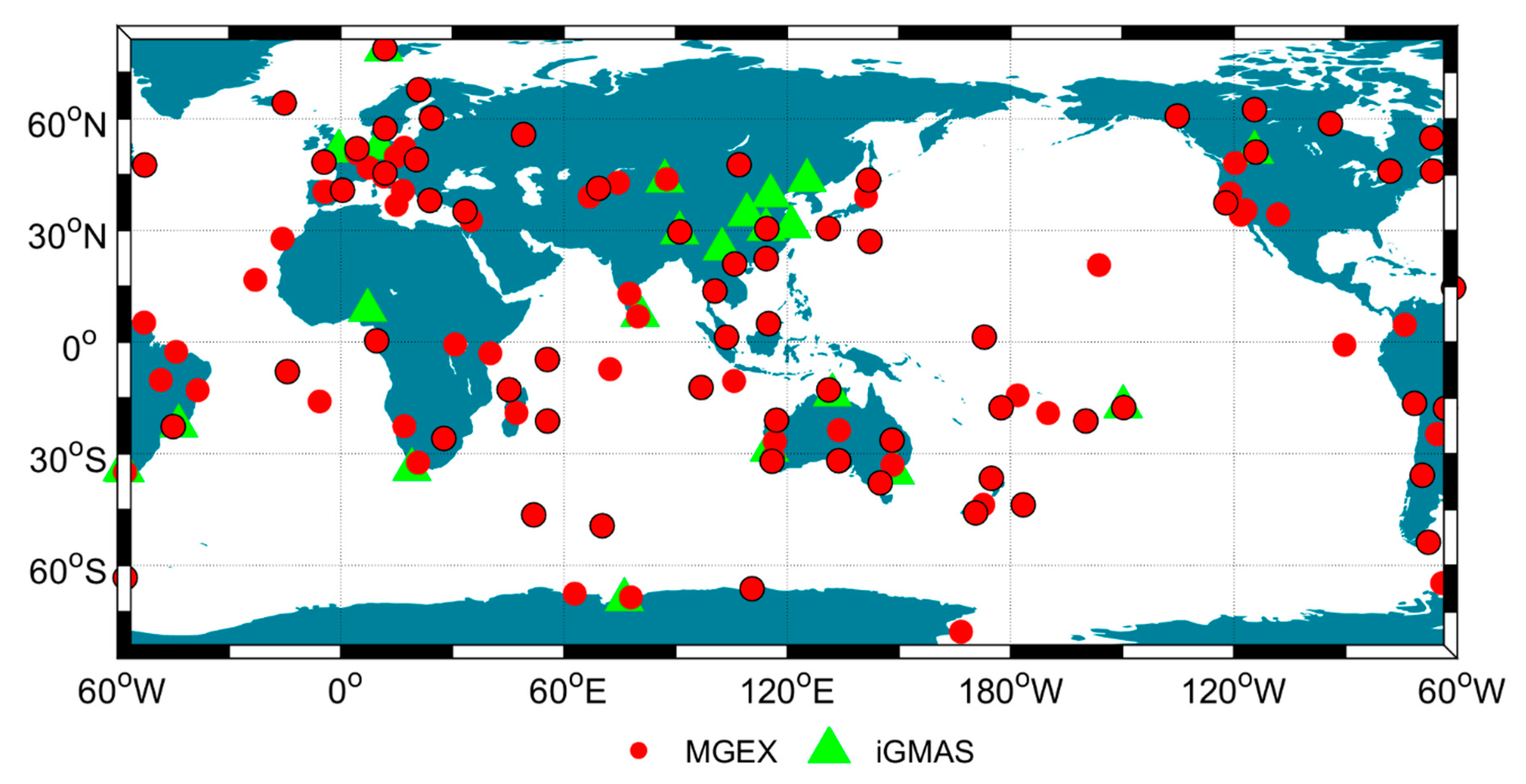
We firstly performed the integrated POD using global network from MGEX. The ground observations from the 120-station MGEX network are processed as a reference. In order to make a fair comparison, only a 65-station network with a good global distribution from the MGEX we selected is used to perform the integrated POD (shown as red dots with a black circle edge in 
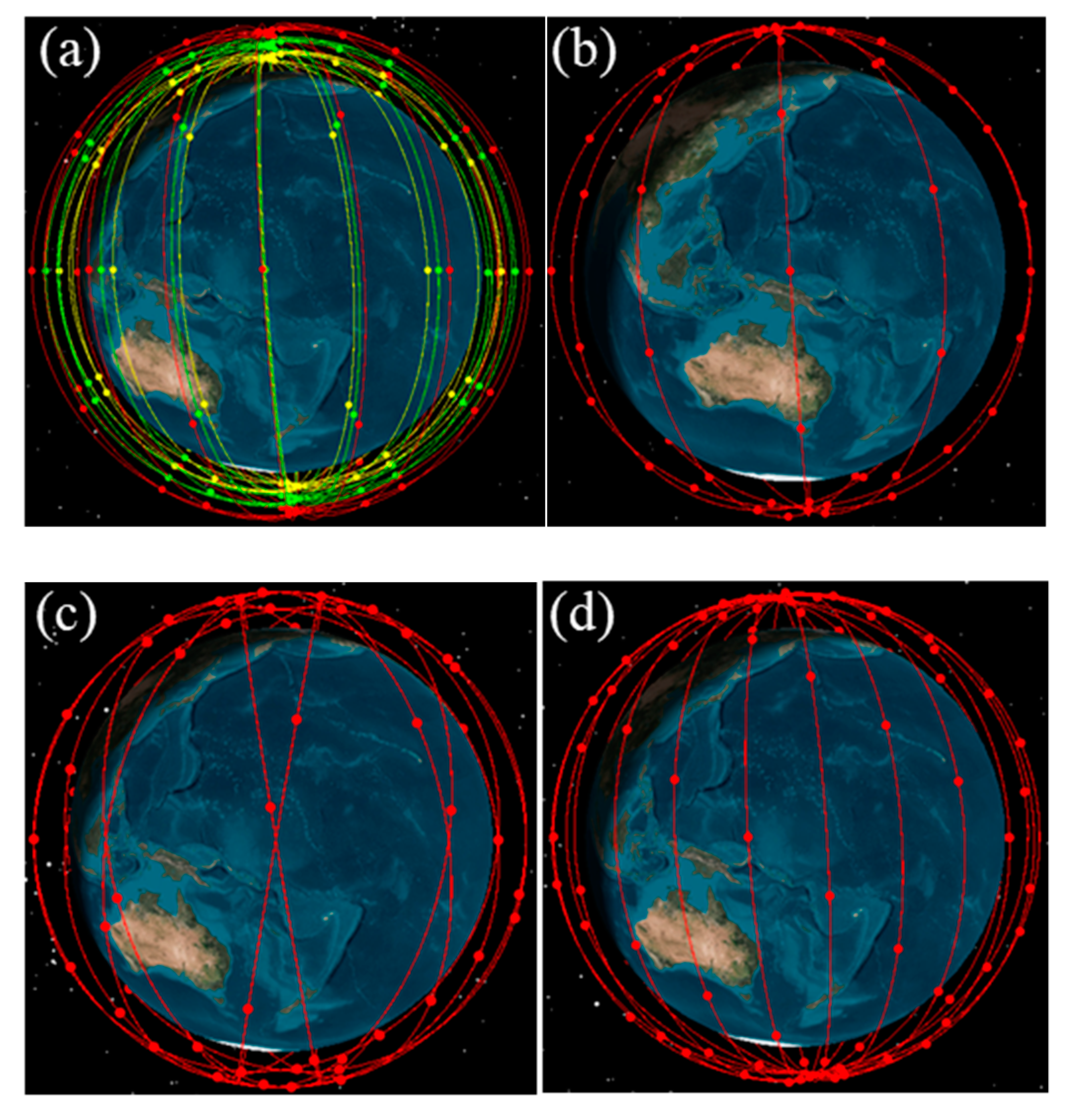
Figure 2). The onboard observations from 60, 66, and 96 polar-orbiting LEO satellites with altitudes of 1000 km (see Figure 1a,b,d) are processed to investigate the influence of LEO numbers on the integrated POD.
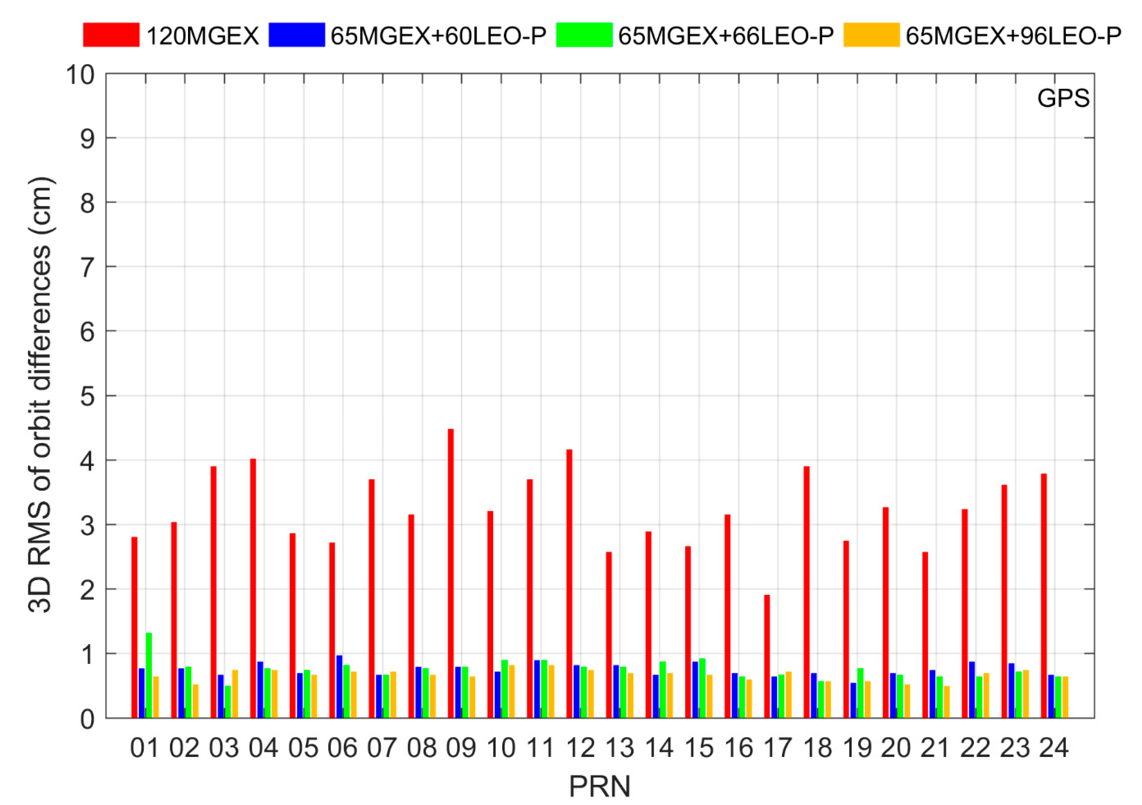
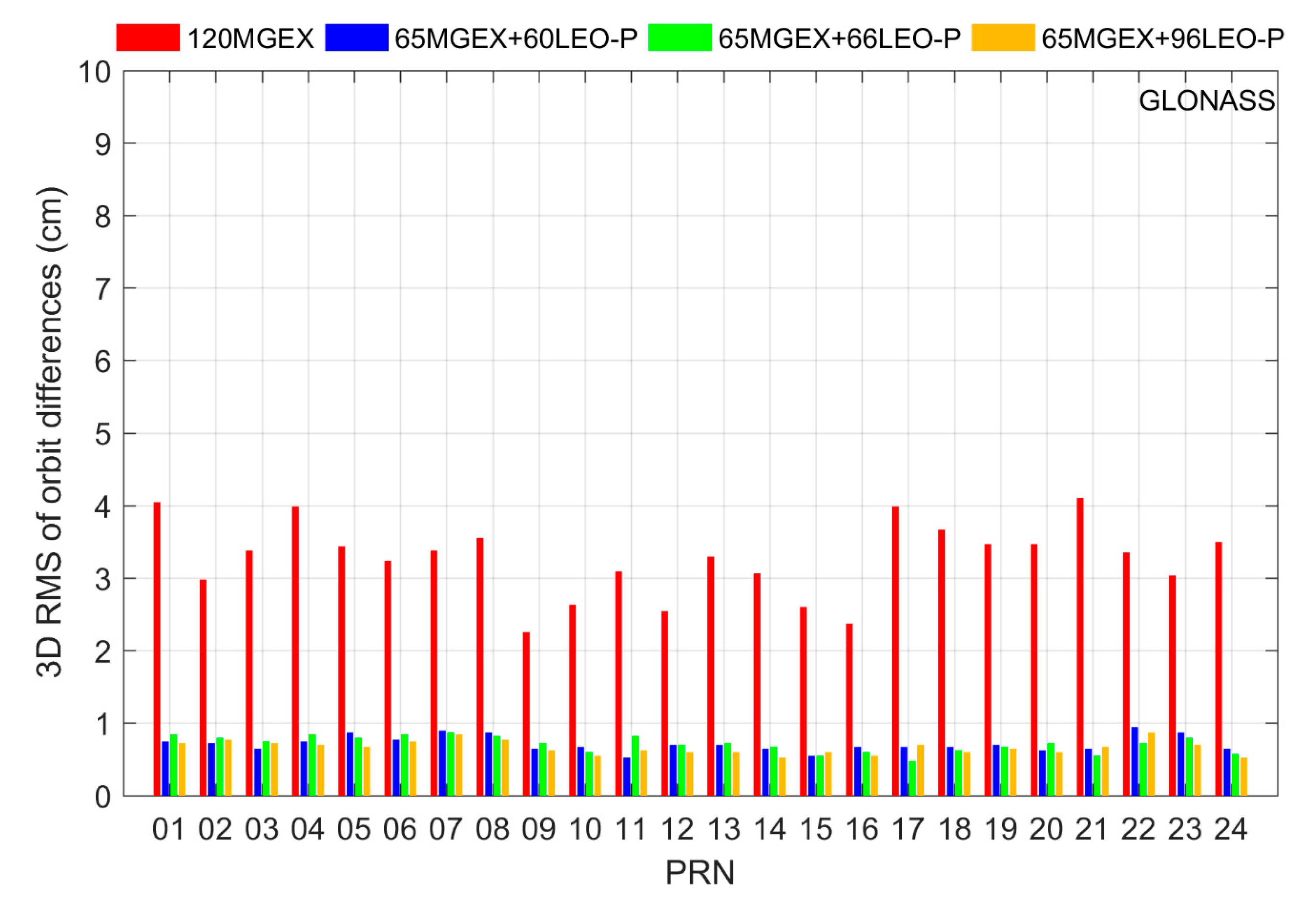
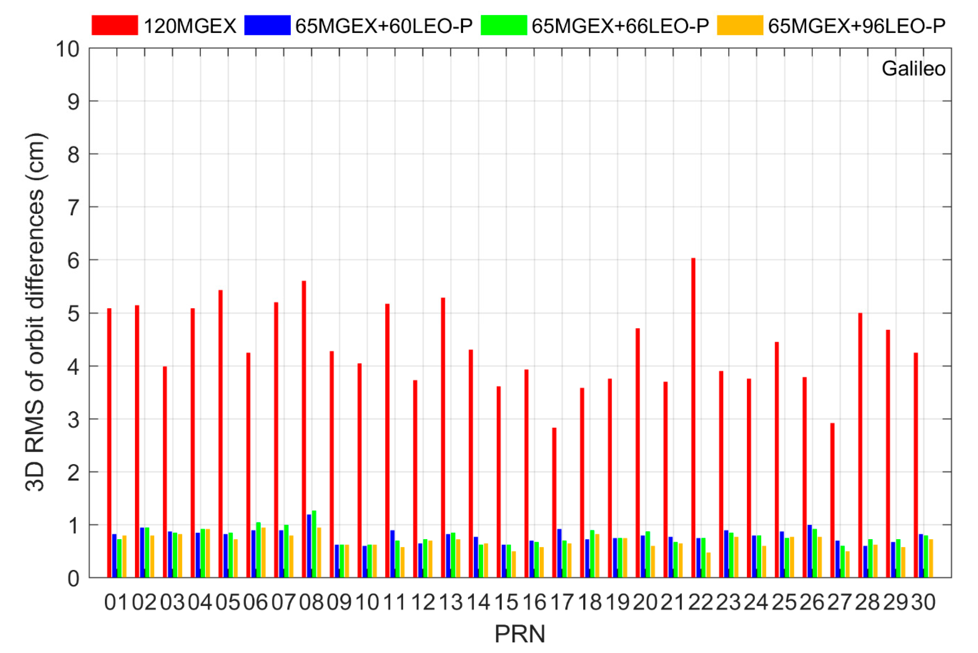
 Figure 3, Figure 4, Figure 5 and Figure 6 present the average 3D Root Mean Square (RMS) values of orbit differences between integrated POD solution and true orbits for all satellites from GPS, GLONASS, Galileo, and BDS constellations respectively. The result shows that by using only the ground multi-GNSS observations, the majority of GNSS satellites can achieve a 3D orbit accuracy of better than 4 cm, which is comparable to the accuracy of the 24-h orbit recovered from the real ground tracking measurements. This demonstrates that the error models and simulation strategy are close to the real situation. Table 4 computes the average 3D RMS of orbit differences for four systems. The worst orbit quality can be found in BDS GEO, and the average 3D RMS values of orbit differences even exceeds 2 m. This is reasonable, because the stationary and regional coverage feature of GEO satellites lead to poor tracking geometry, greatly hampering the orbit determination for GEO satellites.
As shown in Figure 3, Figure 4, Figure 5 and Figure 6, all satellites providing global coverage can achieve a sub-centimeter level orbit with the support of LEO onboard observations, while the orbit accuracy of regional coverage satellites (BDS GEO and IGSO) is at the centimeter level. It can be seen that LEO satellites can make more contributions to GNSS orbits than the same numbers of ground stations, since they can not only provide high-quality observations, but also improve the geometry diversity. The orbit of GNSS satellites obtains a remarkable accuracy improvement after introducing the LEO observations into the POD processing. The accuracy improvement with respect to the ground-based POD result can reach over 70% for all of 60 LEO-, 66 LEO-, and 96 LEO-augmented POD schemes (as shown in Table 4). This indicates that the onboard data from the large LEO constellations can be an important supplement to the GNSS POD, even under the condition of a global network. We find that the BDS GEO satellites present the largest accuracy improvement when the integrated POD is implemented; the improvement percentage even reaches up to about 98%. This inspiring result evidences the contribution of LEO to improve the tracking geometry of GEO satellites.
Furthermore, it can be seen that smaller orbit differences can be achieved when more LEO satellites are introduced into the integrated POD. The 96-LEO solution achieves a slightly better orbit accuracy than the other two LEO-augmented POD solutions. However, compared with the slight accuracy improvement of the 96-LEO solution, introducing additional 30 LEO satellites into the processing of the integrated POD leads to a huge burden on the computational efficiency because of the larger number of unknown parameters to be solved. The average computation time of integrated POD for the 96-LEO scheme is about 38 h, which is almost three times more than that of 60-LEO and 66-LEO schemes (about 13 h).

4.1.2. Integrated POD with Different LEO Orbital Type

To assess the impact of LEO orbital type, two typical LEO orbits, nearly-polar and sun-synchronous orbits, are adopted in this study. Both of LEO constellations consist of 60 LEO satellites flying at an altitude of 1000 km (see Figure 1a,b). The ground observations from a global network with 65 stations are used. The results are shown in Figure 7. It can be seen that the sun-synchronous-orbiting constellation presents a slightly stronger enhancement to the GNSS orbits than the polar-orbiting constellation. With the sun-synchronous-orbiting data of 60 satellites, the orbit of GNSS satellites can achieve an accuracy similar to that of the 96-polar-orbiting scheme, and the orbit accuracy of BDS GEO for the sun-synchronous scheme is even better than that for the 96-polar-orbiting scheme.
As reported by Li et al. [9], the polar-orbiting constellation outperforms the sun-synchronous-orbiting constellation in terms of the convergence time of PPP. However, the situation is reversed when the LEO constellation is employed to enhance the GNSS precise orbit determination. In order to determine the reason for this, we computed the actual number of LEO satellites used for the GNSS POD and calculated an orbit dilution of precision (ODOP) value for every GNSS satellite using a similar algorithm like the position dilution of precision (PDOP) for ground stations. Assuming one GNSS satellite can be tracked by n ground stations simultaneously, the ODOP of this GNSS satellite can be calculated as follows:
H = [ x 1 x s | r 1 | y 1 y s | r 1 | z 1 z s | r 1 | 1 x 2 x s | r 2 | y 2 y s | r 2 | z 2 z s | r 2 | 1 x n x s | r n | y n y s | r n | z n z s | r n | 1 ]
Q = ( H T H ) 1
O D O P = Q ( 1 , 1 ) + Q ( 2 , 2 ) + Q ( 3 , 3 )
where ( x n , y n , z n ) and ( x s , y s , z s ) are the positions of ground station and GNSS satellite respectively. r n = ( x n x s , y n y s , z n z s ) is the distance vector with the direction from GNSS satellite to ground station. The ODOP value describes the geometric strength of observations for GNSS satellites. The better the geometric strength, the smaller the ODOP value. 
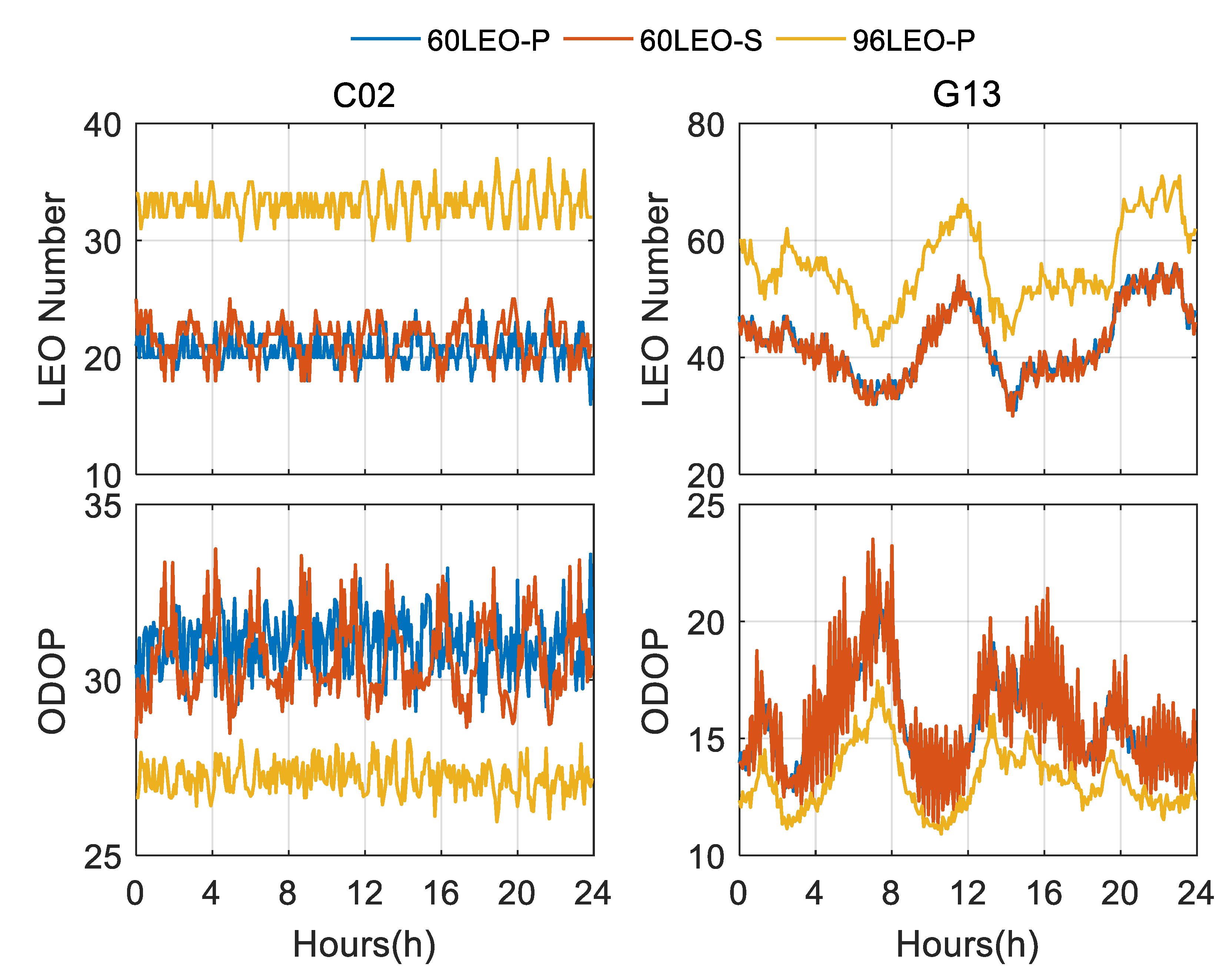
Figure 8 shows the used LEO numbers and ODOP values for C02 (GEO) and G13 (MEO) respectively. The two 60-LEO schemes contribute an almost comparable number of LEO satellites to the orbit determination for BDS GEO C02. The average number of the used sun-synchronous-orbiting LEO satellite is 21.5, which is slightly larger than polar-orbiting LEO number, i.e., 20.6. In terms of ODOP, the ODOP values of the sun-synchronous-orbiting constellation present a stronger fluctuation with a larger amplitude than those of polar-orbiting constellation. For BDS GEO satellites, the changeless tracking geometry is the key limitation of their orbit determination. The main contribution of LEO satellites is to bring a fast variation to the tracking geometry for BDS GEO. The faster fluctuation of ODOP indicates that the sun-synchronous-orbiting constellation can bring more variations to the GEO tracking geometry, which can yield more pronounced orbit accuracy improvements for GEO satellites. For the 96-LEO solution, more available LEO satellites are introduced compared with the two 60-LEO solutions. Though the 96-LEO solution presents smaller ODOP values, a more moderate variation can be observed in GEO ODOP values for the 96-LEO solution compared with the 60 sun-synchronous-orbiting solution. The slow variation of ODOP values for the 96-LEO scheme may be the reason why the 96-LEO solution achieves a relatively worse orbit quality of GEO than the 60 sun-synchronous-orbiting solution. In the case of satellite G13, the differences between the ODOP variation of the two 60-LEO solutions is small, which leads to a relatively small discrepancy in the corresponding orbit accuracy, i.e., 1 mm.

4.1.3. Integrated POD with Different LEO Altitude

Table 5 lists the result of the integrated POD with LEO satellites at different altitudes. The 60 polar-orbiting LEO satellites at altitudes of 600, 1000, and 1400 km are considered (see Figure 1a). It can be seen that there are almost no orbit accuracy differences among the solutions. The integrated POD with higher LEO satellites presents a slightly higher orbit quality than that with lower LEO satellites, except for the BDS GEO satellites. For BDS GEO, the best orbit accuracy is achieved by the 600 km solution. Given the motionless characteristic of GEO satellites, the LEO satellites orbiting at an altitude of 600 km can contribute more improvements to the tracking geometry for BDS GEO due to their faster motion, which may be the reason for the better performance of the 600-km solution in GEO orbit accuracy. In addition, it should be noted that the LEO satellites at low altitude usually suffer from complex SRP modelling. Also, the trajectory of low-altitude LEO is perturbed by a stronger drag force, which will increase the difficulty of drag force modeling and lead to accelerated orbital decay for LEO. The difficulty of air drag and SRP modelling may negatively affect the result of the integrated POD. Fortunately, with the proper modeling of these forces, such as estimating the drag parameter with a shorter interval, low-altitude LEO satellites can obtain a high precision orbit result, which has been evidenced in many low-altitude LEO missions, such as Swarm [38].

4.1.4. Integrated POD with Different Ground Network

In order to evaluate the impact of station quantity and distribution on the LEO-augmented POD, fewer global stations are selected to perform the integrated POD with different LEO constellations. We firstly adopted about 22 global stations from iGMAS (see Figure 2). Typically, the three LEO schemes, i.e., 60 polar-orbiting LEO, 60 sun-synchronous-orbiting LEO, and 96 polar-orbiting LEO constellations at the altitude of 1000 km, are chosen.
Figure 9 illustrates the integrated POD results for GPS, GLONASS, Galileo, and BDS using iGMAS ground observations. For comparison, we also plot the GNSS orbit results determined from the 65 MGEX stations and 60 sun-synchronous-orbiting LEO satellites. The corresponding statistical values are provided in Table 6. With regard to the numbers provided in Table 4, a clear degradation in the orbit accuracy can be recognized for all GNSS satellites compared with the POD result using MGEX network when only ground iGMAS observations are processed. This is reasonable, because fewer ground stations are employed to recover GNSS satellites orbit. Similar to the MGEX solution, the significant orbit accuracy improvement for all satellites can be recognized after the incorporation of LEO onboard observations into the GNSS orbit determination. Certainly, BDS GEO satellites exhibit the largest orbit accuracy improvement. The different LEO constellations present a similar performance to that in the MGEX solution. As shown in Table 6, the sun-synchronous-orbiting constellation yields slightly better performance in LEO-augmented POD compared to the two polar-orbiting constellations.
Meanwhile, it should be noted that although a sparse iGMAS network is employed to perform the integrated POD, the orbit accuracy of all three iGMAS integrated POD schemes is comparable to that of the corresponding MGEX solutions. The performance of the iGMAS and MGEX solutions mainly differs in their estimated BDS GEO orbits. Compared with the MGEX solution, the integrated POD with the iGMAS network provides a relatively worse orbit for the BDS GEO. The result demonstrates that the dependence of GNSS orbit determination on the ground stations can be largely reduced when introducing a large number of LEO satellites into the POD processing. Serving as moving stations, LEO satellites can not only provide a large amount of onboard observations, but also bring evident improvements to the tracking geometry for GNSS satellites.
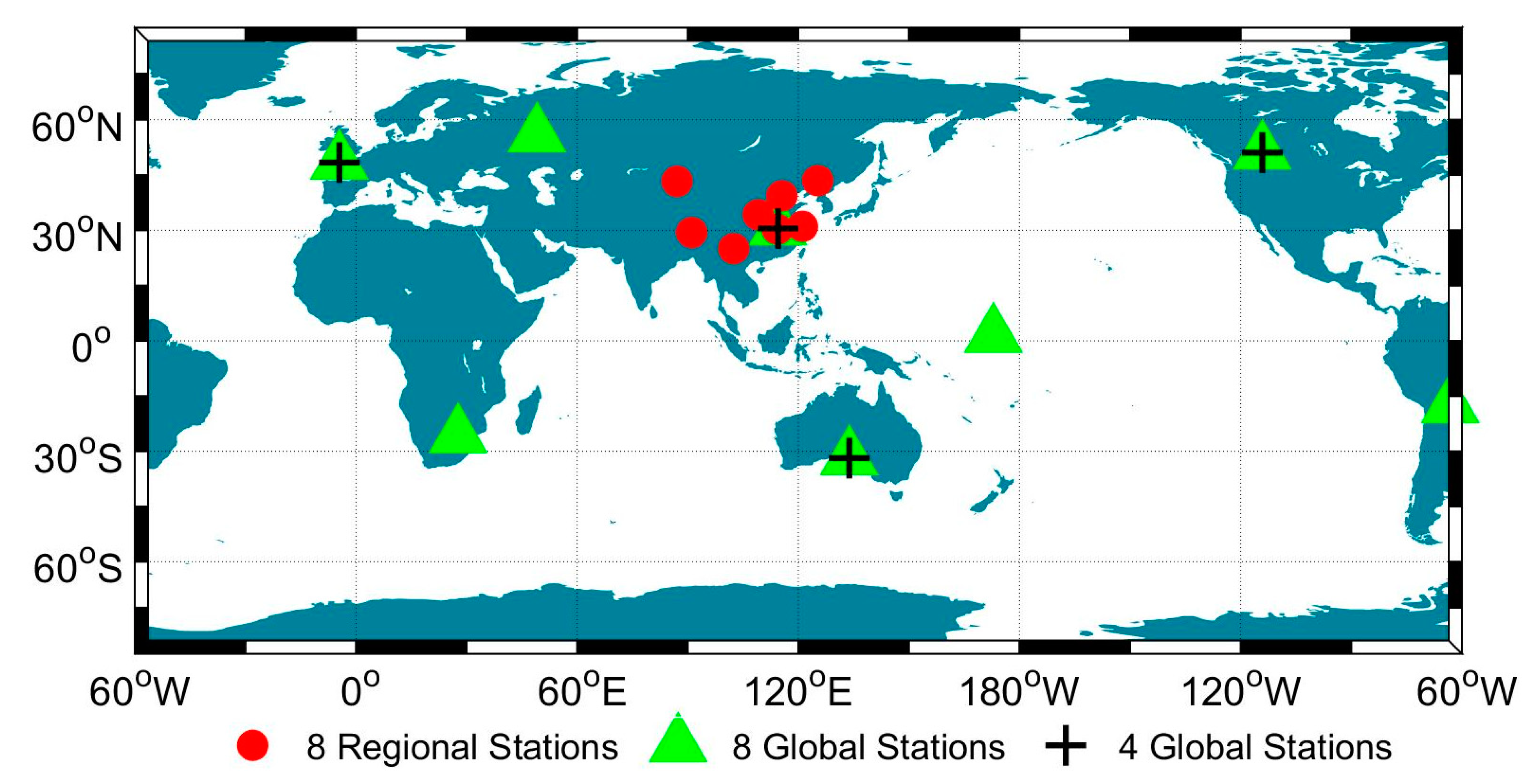
The above results indicate that the onboard observations play an important role in reducing the contribution of ground observations to GNSS orbit determination when introducing a large number of LEO satellites. To further investigate the dependency of the integrated POD on the ground stations, we design three integrated POD schemes with only 8 or 4 ground stations involved. The distribution of the small number of stations we selected is shown in Figure 10. The sun-synchronous-orbiting constellation with 60 LEO satellites is adopted due to its best performance in the previous study. It should be noted that the earth rotation parameters are fixed when we perform the integrated POD with a few stations.
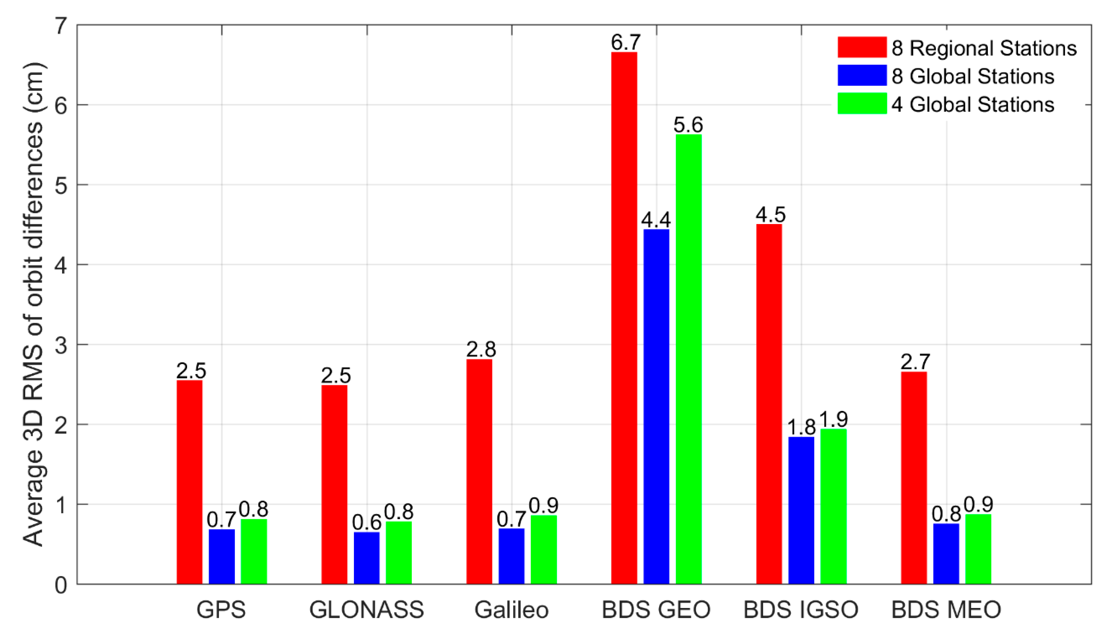
As shown in Figure 11, the estimated orbit of the integrated POD with 8 regional stations can achieve a centimeter-level accuracy, which is better than the POD result only using ground MGEX observations (see Table 4). This indicates that with the assistance of 60 LEO satellites, only using observations from regional stations can already obtain a relatively high-quality satellite orbit. A significant reduction in orbit difference can be recognized for all the GNSS satellites when the 8 regional stations are replaced by 8 global stations. We can find that the orbit accuracy of the integrated POD with 8 global stations is almost in line with the accuracy of the corresponding MGEX and iGMAS integrated POD schemes. The accuracy improvement can be attributed to the better performance of the globally distributed stations in anchoring the whole constellations compared to the regional stations. Slight orbit degradation for GNSS satellites is observed when the number of global stations is reduced to 4. The result shows that the POD of GNSS satellites has less dependence on the number of ground stations and is more sensitive to the distribution of ground stations after the inclusion of the large LEO constellation.

4.2. Integrated POD with Partial LEO Constellation

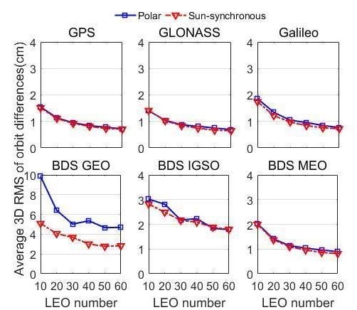
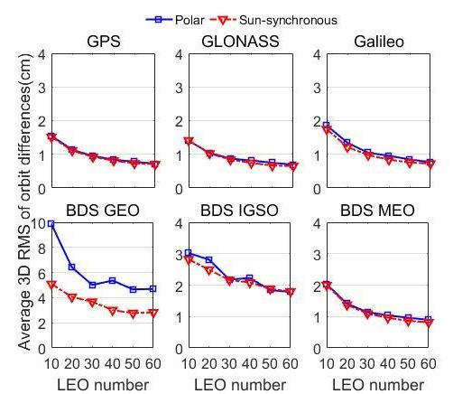
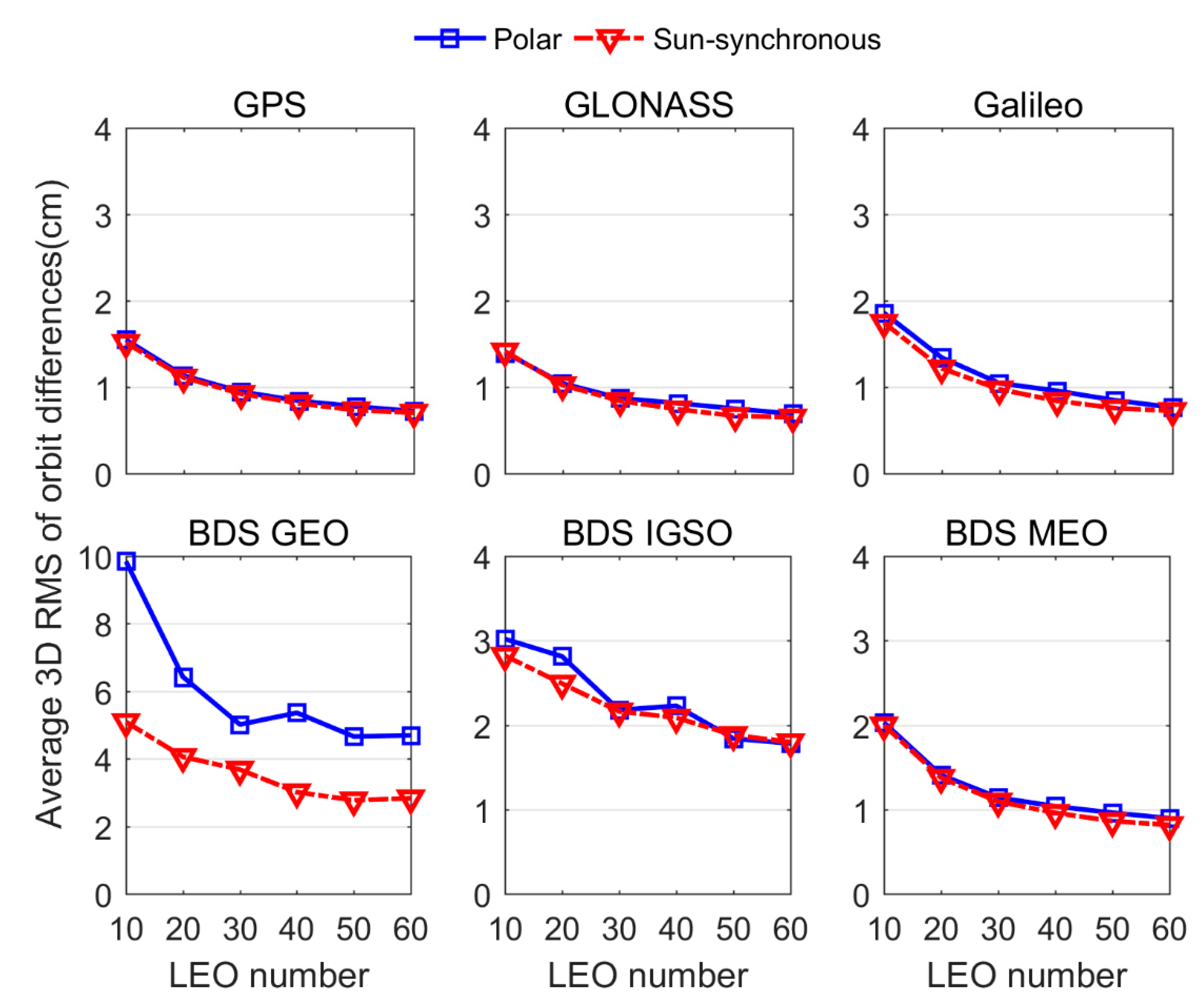
The previous results demonstrate the strong enhancement of the entire LEO constellation to the GNSS orbit estimation. However, it can be seen that the integrated POD suffers from a long computation time when a large number of LEO satellites are introduced. The computation time of the 60-LEO scheme is about 13 h, while for 96-LEO scheme, it reaches about 38 h. Only moderate accuracy differences are obtained for the 60-, 66- and 96-LEO constellations. In order to balance the conflict between orbit accuracy and computational efficiency, it is worthwhile to investigate the integrated POD with a partial LEO constellation, and to explore how many LEO satellites can be used as an auxiliary to improve the orbit accuracy of GNSS satellites. In this section, we process the observation from 65 MGEX stations and a partial LEO constellation. The 60 polar-orbiting LEO constellation and 60 sun-synchronous-orbiting LEO constellation at an altitude of 1000 km are chosen.
Figure 12 shows the average 3D RMS of GNSS orbit differences for the integrated POD as a function of the number of LEOs. We find that with only adding 10 LEO satellites, BDS GEO satellite orbits can already achieve an accuracy of better than 10 cm, while the orbit differences of other satellites are below 2 cm. The corresponding computation time is less than 2 h (shown in Figure 13). This result indicates that the introduction of a small number of LEO satellites can not only obtain a relatively high accuracy GNSS orbit, but that it also limits the computation time, which is very beneficial to the GNSS application with high timeliness requirements. For both, the orbit differences of GNSS satellites decrease monotonically as the number of introduced LEO satellites increases. However, with more LEO satellites included, the improvement of orbit accuracy gradually becomes smaller. A reduction of about 0.5–4 cm can be observed in the orbit differences when the LEO increases from 10 to 20, whereas the additional 10 LEO satellites can only contribute to an accuracy improvement of less than 0.2 cm as the LEO increases from 40 to 50. On the other hand, the increase of LEO satellites introduces a large number of parameters to be estimated, resulting in a steep rise in computational time (shown in Figure 13). For example, the computation time of the integrated POD greatly rise from 9.46 h to 13.42 h when the LEO number increases from 50 to 60. But the addition of 10 LEO satellites only yields an orbit accuracy improvement of about 1 mm for the majority of GNSS satellites.
In addition, it can be seen that the sun-synchronous LEO satellites exhibit a stronger enhancement to the GNSS orbits than those in nearly-polar orbit, no matter how many LEO satellites are introduced. The accuracy differences between the sun-synchronous LEO scheme and nearly-polar LEO scheme is very small for the GPS, GLONASS, Galileo, BDS IGSO, and MEO satellites. This is because the relative motion between these satellites and ground stations already yields good geometric diversity, so that the small contribution differences in tracking geometry between sun-synchronous LEO and nearly-polar LEO satellites have little impact on the orbit determination of these satellites. However, differences of more than 1 cm are visible in the BDS GEO orbits between the two solutions. Evidently, the combination of global stations and sun-synchronous LEO satellites result in better quality GEO orbits. This is because LEO satellites in sun-synchronous orbit can give rise to faster variations of observation geometry for BDS GEO satellites (see Figure 8).

5. Discussion

Serving as moving stations, the LEO satellites can significantly strengthen the tracking geometric diversity of GNSS satellites and improve the accuracy of the GNSS precise orbit determination, particularly in the case of regional network or sparse global network. Although many studies have reported the contribution of LEO onboard observations to the GNSS POD, few studies have focused on the performance of the integrated POD with a large LEO constellation. Meanwhile, the impact factors of the integrated POD, such as LEO number, orbital height, and orbit type, is barely analyzed. In this study, we presented the GNSS orbit solution derived in an integrated processing of the ground network and the large LEO constellation using simulated data. Six LEO constellations are designed to study the performance of the integrated POD with different tracking configurations. The results demonstrate that the orbit accuracy of GNSS satellites can be dramatically improved when a large number of LEO satellites is introduced; the more LEO satellites, the better the orbit accuracy. Notably, BDS GEO orbits present an accuracy of a few centimeters with the recruitment of LEO satellites. Moreover, the LEO satellite in sun-synchronous orbit can contribute more to GNSS orbits than nearly polar-orbiting satellites, since they give rise to a stronger observation geometry. Furthermore, the orbit altitude of LEO satellites is found to have no evident impact on the GNSS satellites except BDS GEO satellites. In addition, it can be seen that the integrated POD with the entire LEO constellation suffers from a long computational time because of the abundant GNSS observations to be processed and the large number of parameters to be estimated. The long computation time of the integrated POD cannot meet the timeliness requirement of the real-time precise positioning. This weakness in terms of computational efficiency can be overcome by just introducing a certain number of LEO satellites.
Although our study presents an optimistic integrated POD result due to the simulated data, the impact of introducing LEO constellations to improve GNSS orbit determination is clearly demonstrated. Indeed, not only tracking geometry, but many other factors, such as attitude model, solar radiation pressure and drag models, and antenna calibrations, constitute key limitations in real-world LEO and GNSS POD. Fortunately, with the efforts of many scientists, the force and observation models have been rigorously refined in recent years, which can reduce the impact of model errors on the GNSS POD as much as possible. Using the current models, GNSS satellites (except BDS GEO) can achieve centimeter-level orbits [1], though more efforts are needed to further refine the force and observation models. Meanwhile, the force model errors do not represent a weakness in the observability and tracking geometry, which is a separate issue from the tracking geometry that needs to be further investigated. In addition, except for the factors mentioned above, there are still many issues which need to be taken into consideration when implementing the integrated POD using real GNSS observations. For example, the incorporation of a large number of real multi-GNSS onboard observations may introduce unexpected unmodeled errors into the orbit recovery process. Meanwhile, different from ground receivers, the performance of space-borne receivers can be more easily affected by the space environment due to the high altitude, i.e., 600 km~1000 km, where LEO satellites are flying. As discussed in Xiong et al. [39], large equatorial plasma irregularities can degrade the tracking capability of the Swarm onboard receivers, leading to severe signal loss at low latitudes. This loss of signal for space-borne receivers undoubtedly has negative effects on the integrated POD. Moreover, except for GNSS data, many other types of satellite tracking data are not considered in our study. Once the construction of the navigation augmentation LEO constellation is complete, the new ranging observations from LEO satellites to ground stations can be employed. These new types of satellite tracking data are expected to remove the potential systemic bias in the estimated orbits and further improve the orbit accuracy of both GNSS and LEO satellites.

6. Conclusions

This paper is devoted to investigating the integrated precise orbit determination with large LEO constellations. We performed LEO-augmented multi-GNSS precise orbit determination in this study. Based on simulated GNSS observations, several integrated POD schemes are implemented to investigate the performance of integrated POD under different tracking conditions. The potential influence factors of the integrated POD, including LEO satellites number, altitude, and orbit type as well as ground station number and distribution, are analyzed and discussed in detail.
The result shows that joint processing ground observations from the global network and the large LEO constellation onboard observations can significantly improve the orbit accuracy for GNSS satellites, especially for BDS GEO satellites. The accuracy improvement percentage with respect to the ground-based POD results can reach over 70% for all the integrated POD schemes with 60-, 66-, 96-LEO satellites. The largest orbit accuracy improvement of over 98% can be recognized for BDS GEO, since the fast motion of LEO satellites brings tremendous variations to the tracking geometry of GEO satellites. By incorporating a large number of LEO satellites, BDS GEO satellites can obtain a centimeter-level orbit. Compared with the 60- and 66-LEO schemes, a slightly better orbit quality is observed in the 96 LEO scheme due to the introduction of more LEO satellites. However, the increase of the involved LEO satellites results in a sharp rise in the computational time of the integrated POD because of more unknown parameters to be solved. We also present the impact of the LEO orbit type on the integrated POD. With the same number of LEO satellites, the sun-synchronous-orbiting constellation presents a stronger enhancement to GNSS orbits than the polar-orbiting constellation. The improvement can be attributed to the more rapid variation of GNSS tracking geometry provided by a sun-synchronous-orbiting constellation. In terms of the LEO altitude, the orbit altitude of LEO satellites is found to have little influence on the enhancement to GNSS orbits except for with BDS GEO satellites. Benefiting from the faster motion of lower LEO satellites, the 600 km scheme achieves a better orbit accuracy for BDS GEO than the 1000 km and 1400 km schemes.
In order to assess the impact of station number and distribution, global and regional networks with different numbers of stations are employed. With the inclusion of large LEO constellation, the integrated POD appears to be more sensitive to the distribution of ground stations, rather than the station number. This is because in the integrated POD, the dependence of GNSS orbit determination on ground stations is largely reduced by the onboard GNSS observations when a large LEO constellation is considered. Based on 8 regional stations, the orbit accuracy of the integrated POD with a sun-synchronous-orbiting constellation is at the centimeter level. However, a subcentimeter accuracy can be recognized for the orbits of GNSS satellites when 8 globally distributed stations are adopted, which is comparable to the result of the integrated POD with a denser global network of 65 stations.
Although GNSS orbit estimations can greatly benefit from the incorporation of a full LEO constellation, the integrated POD suffers from long computation time due to the addition of a large number of LEO satellites. To balance the conflict between orbit accuracy and computational efficiency, the integrated POD with a partial LEO constellation is investigated. The orbit accuracy of GNSS satellites improves gradually as the LEO satellites increase. The more LEO satellites, the better the orbit accuracy. However, with an increasing number of LEOs, the accuracy improvement of GNSS orbits becomes smaller. Meanwhile, the increase of LEO satellites results in a steep rise in computational time. Considering both orbit accuracy and computational efficiency, we prefer 40 LEO satellites in a sun-synchronous orbit.
With the rapid development of the LEO constellations, we expect an improvement of GNSS POD when jointly processing GNSS observation data from reference sites and LEOs. Continued efforts for force modeling, algorithm optimization, and scheme design are required to achieve better performance of the integrated POD.

Author Contributions

All authors contributed to the writing of this manuscript. X.L., K.Z., and F.M. conceived and designed the experiments. K.Z., W.Z. and Q.Z. processed the data, drew the pictures, and investigated the results. Y.Q., H.Z., Y.M. and L.B. validated the data.

Funding

This study is financially supported by the National Natural Science Foundation of China (Grant No. 41774030, No. 41974027, No. 41974029), and the Hubei Province Natural Science Foundation of China (Grant No. 2018CFA081).

Acknowledgments

We are very grateful to the International GNSS Service (IGS) for providing the multi-GNSS data and the precise orbit and clock products of multi-GNSS constellation at the IGS website (ftp://cddis.gsfc.nasa.gov). Thanks also go to the EPOS-RT/PANDA software from GFZ. The numerical calculations in this paper have been done on the supercomputing system in the Supercomputing Center of Wuhan University.

Conflicts of Interest

The authors declare no conflict of interest.

References

  1. Montenbruck, O.; Steigenberger, P.; Prange, L.; Deng, Z.; Zhao, Q.; Perosanz, F.; Romero, I.; Noll, C.; Stürze, A.; Weber, G.; et al. The Multi-GNSS Experiment (MGEX) of the International GNSS Service (IGS)—Achievements, Prospects and Challenges. Adv. Space Res. 2017, 59, 1671–1697. [Google Scholar] [CrossRef]
  2. Dai, X.; Ge, M.; Lou, Y.; Shi, C.; Wickert, J.; Schuh, H. Estimating the yaw-attitude of BDS IGSO and MEO satellites. J. Geod. 2015, 89, 1005–1018. [Google Scholar] [CrossRef]
  3. Guo, J.; Chen, G.; Zhao, Q.; Liu, J.; Liu, X. Comparison of solar radiation pressure models for BDS IGSO and MEO satellites with emphasis on improving orbit quality. GPS Solut. 2016, 21, 511–522. [Google Scholar] [CrossRef] [Green Version]
  4. Montenbruck, O.; Steigenberger, P.; Hugentobler, U. Enhanced solar radiation pressure modeling for Galileo satellites. J. Geod. 2015, 89, 283–297. [Google Scholar] [CrossRef]
  5. Zhao, Q.; Guo, J.; Li, M.; Qu, L.; Hu, Z.; Shi, C.; Liu, J. Initial results of precise orbit and clock determination for COMPASS navigation satellite system. J. Geod. 2013, 87, 475–486. [Google Scholar] [CrossRef]
  6. Guo, F.; Li, X.; Zhang, X.; Wang, J. Assessment of precise orbit and clock products for Galileo, BeiDou, and QZSS from IGS Multi-GNSS Experiment (MGEX). GPS Solut. 2016, 21, 279–290. [Google Scholar] [CrossRef]
  7. Li, X.; Li, X.; Yuan, Y.; Zhang, K.; Zhang, X.; Wickert, J. Multi-GNSS phase delay estimation and PPP ambiguity resolution: GPS, BDS, GLONASS, Galileo. J. Geod. 2018, 92, 579–608. [Google Scholar] [CrossRef]
  8. Ke, M.; Lv, J.; Chang, J.; Dai, W.; Tong, K.; Zhu, M. Integrating GPS and LEO to accelerate convergence time of precise point positioning. In Proceedings of the 7th International Conference on Wireless Communications and Signal, Nanjing, China, 15–17 October 2015; IEEE: Piscataway, NJ, USA, 2015; pp. 1–5. [Google Scholar]
  9. Li, X.; Ma, F.; Li, X.; Lv, H.; Bian, L.; Jiang, Z.; Zhang, X. LEO constellation-augmented multi-GNSS for rapid PPP convergence. J. Geod. 2019, 93, 749–764. [Google Scholar] [CrossRef]
  10. Li, B.; Ge, H.; Ge, M.; Nie, L.; Shen, Y.; Schuh, H. LEO enhanced Global Navigation Satellite System (LeGNSS) for real-time precise positioning services. Adv. Space Res. 2018, 63, 73–93. [Google Scholar] [CrossRef]
  11. Li, X.; Li, X.; Ma, F.; Yuan, Y.; Zhang, K.; Zhou, F.; Zhang, X. Improved PPP ambiguity resolution with the assistance of multiple LEO constellations and signals. Remote Sens. 2019, 11, 408. [Google Scholar] [CrossRef]
  12. Li, X.; Lv, H.; Ma, F.; Li, X.; Liu, J.; Jiang, Z. GNSS RTK positioning augmented with large LEO constellation. Remote Sens. 2019, 11, 228. [Google Scholar] [CrossRef]
  13. Ge, H.; Li, B.; Ge, M.; Zang, N.; Nie, L.; Shen, Y. Initial Assessment of Precise Point Positioning with LEO Enhanced Global Navigation Satellite Systems (LeGNSS). Remote Sens. 2018, 10, 984. [Google Scholar] [CrossRef]
  14. Zhu, S.; Reigber, C.; König, R. Integrated adjustment of CHAMP, GRACE, and GPS data. J. Geod. 2004, 78, 103–108. [Google Scholar] [CrossRef]
  15. Boomkamp, H.; Dow, J. Use of double difference observations in combined orbit solutions for LEO and GPS satellites. Adv. Space Res. 2005, 36, 382–391. [Google Scholar] [CrossRef]
  16. König, R.; Reigber, C.; Zhu, S. Dynamic model orbits and earth system parameters from combined GPS and LEO data. Adv. Space Res. 2005, 36, 431–437. [Google Scholar] [CrossRef]
  17. Geng, J.; Shi, C.; Zhao, Q.; Ge, M.; Liu, J. Integrated adjustment of LEO and GPS in precision orbit determination. In VI Hotine–Marussi Symposium on Theoretical and Computational Geodesy; Springer: Berlin, Germany, 2008; pp. 33–137. [Google Scholar]
  18. Zoulida, M.; Pollet, A.; Coulot, D.; Perosanz, F.; Loyer, S.; Biancale, R.; Rebischung, P. Multi-technique combination of space geodesy observations: Impact of the Jason-2 satellite on the GPS satellite orbits estimation. Adv. Space Res. 2016, 58, 1376–1389. [Google Scholar] [CrossRef]
  19. Männel, B.; Rothacher, M. Geocenter variations derived from a combined processing of LEO- and ground-based GPS observations. J. Geod. 2017, 91, 933–944. [Google Scholar] [CrossRef]
  20. Zeng, T.; Sui, L.; Jia, X.; Lv, Z.; Ji, G.; Dai, Q.; Zhang, Q. Validation of enhanced orbit determination for GPS satellites with LEO GPS data considering multi ground station networks. Adv. Space Res. 2019, 63, 2938–2951. [Google Scholar] [CrossRef]
  21. Li, X.; Zhang, K.; Zhang, Q.; Zhang, W.; Yuan, Y.; Li, X. Integrated orbit determination of FengYun-3C, BDS, and GPS satellites. J. Geophys. Res. Solid Earth 2018, 123, 8143–8160. [Google Scholar] [CrossRef]
  22. DOD SPS. Department of Defense USA. Global Positioning System Standard Positioning Service Performance Standard, 4th ed.; Department of Defense USA: Washington, DC, USA, 2008. Available online: http://www.gps.gov/technical/ps/2008-SPSperformancestandard (accessed on 6 January 2012).
  23. Global Navigation Satellite System GLONASS–Interface Control Document; v5.1; Russian Institute of Space Device Engineering: Moscow, Russian, 2008.
  24. OS-SIS-ICD. European GNSS (Galileo) Open Service Signal in Space Interface Control Document; SISICD-2006; European Space Agency: Paris, France, 2010. [Google Scholar]
  25. CSNO. BeiDou Navigation Satellite System Signal in Space Interface Control Document-Open Service Signal; Version 3.0; China Satellite Navigation Office: Beijing, China, 2019.
  26. Rebischung, P.; Schmid, R. IGS14/igs14.atx: A new framework for the IGS products. In Proceedings of the AGU Fall Meeting, San Francisco, CA, USA, 12–16 December 2016; Available online: https://mediatum.ub.tum.de/?id=1341338 (accessed on 15 December 2016).
  27. Schaer, S. Overview of relevant GNSS biases. In Proceedings of the IGS workshop on GNSS Biases, University of Bern, Bern, Switzerland, 18–19 January 2012. [Google Scholar]
  28. Guo, F.; Zhang, X.; Wang, J. Timing group delay and differential code bias corrections for BeiDou positioning. J. Geod. 2015, 89, 427–445. [Google Scholar] [CrossRef]
  29. Saastamoinen, J. Atmospheric correction for the troposphere and stratosphere in radio ranging of satellites. The use of artificial satellites for geodesy. Am. Geophys. Union Geophys. Monogr. Ser. 1972, 15, 247–251. [Google Scholar]
  30. Boehm, J.; Niell, A.; Tregoning, P.; Schuh, H. Global mapping function (GMF): A new empirical mapping function based on numerical weather model data. Geophys. Res. Lett. 2006, 33, L07304. [Google Scholar] [CrossRef]
  31. Yizengaw, E.; Moldwin, M.B.; Galvan, D.; Iijima, B.A.; Komjathy, A.; Mannucci, A.J. Global plasmaspheric TEC and its relative contribution to GPS TEC. J. Atmos. Sol. Terr. Phys. 2008, 70, 1541–1548. [Google Scholar] [CrossRef]
  32. Jiao, W.; Ding, Q.; Li, J.; Lu, X.; Feng, L.; Ma, J.; Chen, G. Monitoring and Assessment of GNSS Open Services. J. Navig. 2011, 64 (Suppl. 1), S19–S29. [Google Scholar] [CrossRef]
  33. Förste, C.; Bruinsma, S.; Shako, R.; Marty, J.-C.; Flechtner, F.; Abrykosov, O.; Dahle, C.; Lemoine, J.-M.; Neumayer, K.-H.; Biancale, R. EIGEN-6—A New Combined Global Gravity Field Model Including GOCE Data from the Collaboration of GFZ Potsdam and GRGS Toulouse (Geophysical Research Abstracts Vol.13, EGU2011-3242-2, 2011); General Assembly European Geosciences Union: Vienna, Austria, 2011. [Google Scholar]
  34. Lyard, F.; Lefevre, F.; Letellier, T.; Francis, O. Modelling the global ocean tides: Modern insights from FES2004. Ocean Dyn. 2006, 56, 394–415. [Google Scholar] [CrossRef]
  35. Petit, G.; Luzum, B. IERS Conventions 2010. No.36 in IERS Technical Note; Verlag des Bundesamts für Kartographie und Geodäsie: Frankfurt am Main, Germany, 2010. [Google Scholar]
  36. Beutler, G.; Brockmann, E.; Gurtner, W.; Hugentobler, U.; Mervart, L.; Rothacher, M.; Verdun, A. Extended orbit modeling techniques at the CODE processing center of the international GPS service for geodynamics (IGS): Theory and initial results. Manuscripta Geodaetica 1994, 19, 367–386. [Google Scholar]
  37. Berger, C.; Biancale, R.; Ill, M.; Barlier, F. Improvement of the empirical thermospheric model DTM: DTM94—A comparative review of various temporal variations and prospects in space geodesy applications. J. Geod. 1998, 72, 161–178. [Google Scholar] [CrossRef]
  38. Van Den IJssel, J.; Encarnação, J.; Doornbos, E.; Visser, P. Precise science orbits for the Swarm satellite constellation. Adv. Space Res. 2015, 56, 1024–1055. [Google Scholar] [CrossRef]
  39. Xiong, C.; Stolle, C.; Lühr, H. The Swarm satellite loss of GPS signal and its relation to ionospheric plasma irregularities. Space Weather 2016, 14, 563–577. [Google Scholar] [CrossRef]
Figure 1. LEO constellations designed for augmented GNSS POD. (a) 60 LEO, nearly-polar orbits, 600 km, 1000 km, and 1400 km; (b) 66 LEO (Iridium satellite constellation), nearly-polar orbits, 1000 km; (c) 60 LEO, sun-synchronous orbits, 1000 km; (d) 96 LEO, nearly polar, 1000 km.
Remotesensing 11 02514 g001
Figure 2. Distribution of global stations from MGEX and iGMAS.
Remotesensing 11 02514 g002
Figure 3. Average 3D RMS values of GPS orbit differences for the integrated POD with different numbers of LEO satellites. P denotes the nearly-polar orbit of the LEO constellation.
Remotesensing 11 02514 g003
Figure 4. Average 3D RMS values of GLONASS orbit differences for the integrated POD with different numbers of LEO satellites.
Remotesensing 11 02514 g004
Figure 5. Average 3D RMS values of Galileo orbit differences for the integrated POD with different numbers of LEO satellites.
Remotesensing 11 02514 g005
Figure 6. Average 3D RMS values of BDS orbit differences for the integrated POD with different numbers of LEO satellites.
Remotesensing 11 02514 g006
Figure 7. Average 3D orbit differences RMS of GNSS satellites for the integrated POD with different orbit types of LEO satellites. Values on the top of each bar indicate the corresponding average 3D RMS. P and S denote the nearly-polar and sun-synchronous orbits, respectively.
Remotesensing 11 02514 g007
Figure 8. Time series of used LEO satellites number and the ODOP values for BDS GEO C02 (left) and GPS G13 (right).
Remotesensing 11 02514 g008
Figure 9. Average 3D orbit differences RMS of GNSS satellites for the integrated POD using the iGMAS network. P and S denote the nearly-polar and sun-synchronous orbits, respectively.
Remotesensing 11 02514 g009
Figure 10. Distribution of a small number of ground stations.
Remotesensing 11 02514 g010
Figure 11. Average 3D orbit differences RMS of GNSS satellites for the integrated POD with a few ground stations. Values on the top of each bar indicates the corresponding average 3D RMS.
Remotesensing 11 02514 g011
Figure 12. Average 3D RMS of GNSS orbit differences for the integrated POD with different numbers of LEO satellites.
Remotesensing 11 02514 g012
Figure 13. Number of estimated parameters and computation time of the integrated POD with LEO satellites in nearly-polar orbit.
Remotesensing 11 02514 g013
Table 1. Nominal constellation configuration of GPS, GLONASS, Galileo, and BDS.
GNSSGPSGLONASSGalileoBDS
Orbit typeMEOMEOMEOGEOIGSOMEO
Satellites number2424303324
Altitude20,180 km19,100 km23,220 km35,786 km35,786 km21,528 km
Inclination56°64.8°56°55°55°
ConstellationDistributed in 6 planesWalker (24/3/1)Walker (24/3/1) + 6 backupsLocated at 80°E, 110.5°E, and 140°ERAAN of 118°EWalker (24/3/1)
Total number24243030
Table 2. Detailed information of the designed LEO constellations.
Schemes60LEO-P60LEO-P60LEO-P66LEO-P60LEO-S96LEO-P
Satellite number606060666096
Plane number101010610 12
Altitude600 km1000 km1400 km1000 km1000 km1000 km
Inclination84.6°84.6°84.6°84.6°99.4843°84.6°
Orbit typeNearly-polar circular orbitsNearly-polar circular orbitsNearly-polar circular orbitsNearly-polar circular orbitssun-synchronous circular orbitsNearly-polar circular orbits
Table 3. Detailed processing strategy for the integrated multi-GNSS POD.
ModelDescription
Observation model
ObservationUndifferenced ionosphere-free code & phase
Sampling Interval300s
Arc length24 h
Elevation Mask7° for ground station and 1° for LEO
GNSS PCO&PCVValues used in simulation from igs14.atx
Station PCO&PCVValues used in simulation from igs14.atx
LEO PCO&PCVNone
Force model
Earth gravityEIGEN6C (12×12) for GNSS and EIGEN6C (120×120) for LEO [33]
N-bodyJPL DE405
Ocean tideFES 2004 [34]
RelativityIERS 2010 [35]
Solid tide & Pole tideIERS 2010
Solar radiation pressureECOM model for GNSS [36] and macro-model for LEO
Atmospheric densityDTM94 [37], only considered for LEO
Empirical accelerationsOnly considered for LEO, one set of period parameters per revolution
GNSS estimated parameters
Initial statePosition and velocity at initial epoch
Solar radiation pressureFive ECOM SRP parameters (three constant terms and two periodical terms)
Satellite clock offsetEach epoch as white noise
LEO estimated parameters
Initial statePosition and velocity at initial epoch
Atmospheric dragOne constant scale parameter per 360 min
Empirical accelerationsPiecewise periodical terms in the along-track, cross-track and radial components per revolution
Receiver clock offsetEach epoch as white noise
AmbiguitiesEstimated as float constant values for each continuous arc
Inter-system biasEstimated as constant
Inter-frequency biasEstimated as constant
Ground station estimated parameters
Station coordinateConstraint based on PPP weekly solution
Zenith wet delayOne constant set per 120 min
Receiver clock offsetEach epoch as white noise
AmbiguitiesEach continuous arc. Double-difference ambiguity resolution for the ground network.
Inter-system biasEstimated as constant
Inter-frequency biasEstimated as constant
Earth rotation parametersOne set per arc
Table 4. Average 3D RMS of GNSS orbit differences and improvement percentages with respect to the ground-based POD using MGEX data (Unit: cm).
Satellites120MGEX65MGEX+60LEO-P65MGEX+66LEO-P65MGEX+96LEO-P
RMSPercentageRMS PercentageRMSPercentageRMSPercentage
GPS3.2--0.875.0%0.875.0%0.778.1%
GLONASS3.3--0.778.8%0.778.8%0.778.8%
Galileo4.4--0.881.8%0.881.8%0.784.1%
BDS GEO237.9--4.997.9%4.498.2%3.798.4%
BDS IGSO6.2--1.871.0%1.772.6%1.871.0%
BDS MEO6.0--0.985.0%0.985.0%0.886.7%
Table 5. Average 3D RMS of orbit differences for the integrated POD with different altitude LEO constellations (Unit: cm).
Altitude (km)60010001400
GPS0.80.70.7
GLONASS0.70.70.7
BDS GEO3.64.74.3
BDS IGSO1.81.81.7
BDS MEO1.00.90.9
Galileo0.80.80.8
Table 6. Average 3D RMS values of GNSS orbit differences and improvement percentage with respect to the result of POD using ground iGMAS data (Unit: cm).
SatellitesiGMASiGMAS +60LEO-PiGMAS +60LEO-SiGMAS +96LEO-P
RMSPercentageRMS PercentageRMSPercentageRMSPercentage
GPS7.4--0.889.2%0.790.5%0.790.5%
GLONASS9.7--0.891.8%0.792.8%0.792.8%
Galileo8.8--0.890.9%0.792.0%0.792.0%
BDS GEO237.1--6.197.4%3.898.4%4.898.0%
BDS IGSO6.4--1.871.9%1.871.9%1.871.9%
BDS MEO10.4--0.892.3%0.892.3%0.892.3%

