Detection and Localization for Multiple Stationary Human Targets Based on Cross-Correlation of Dual-Station SFCW Radars


Abstract
1. Introduction
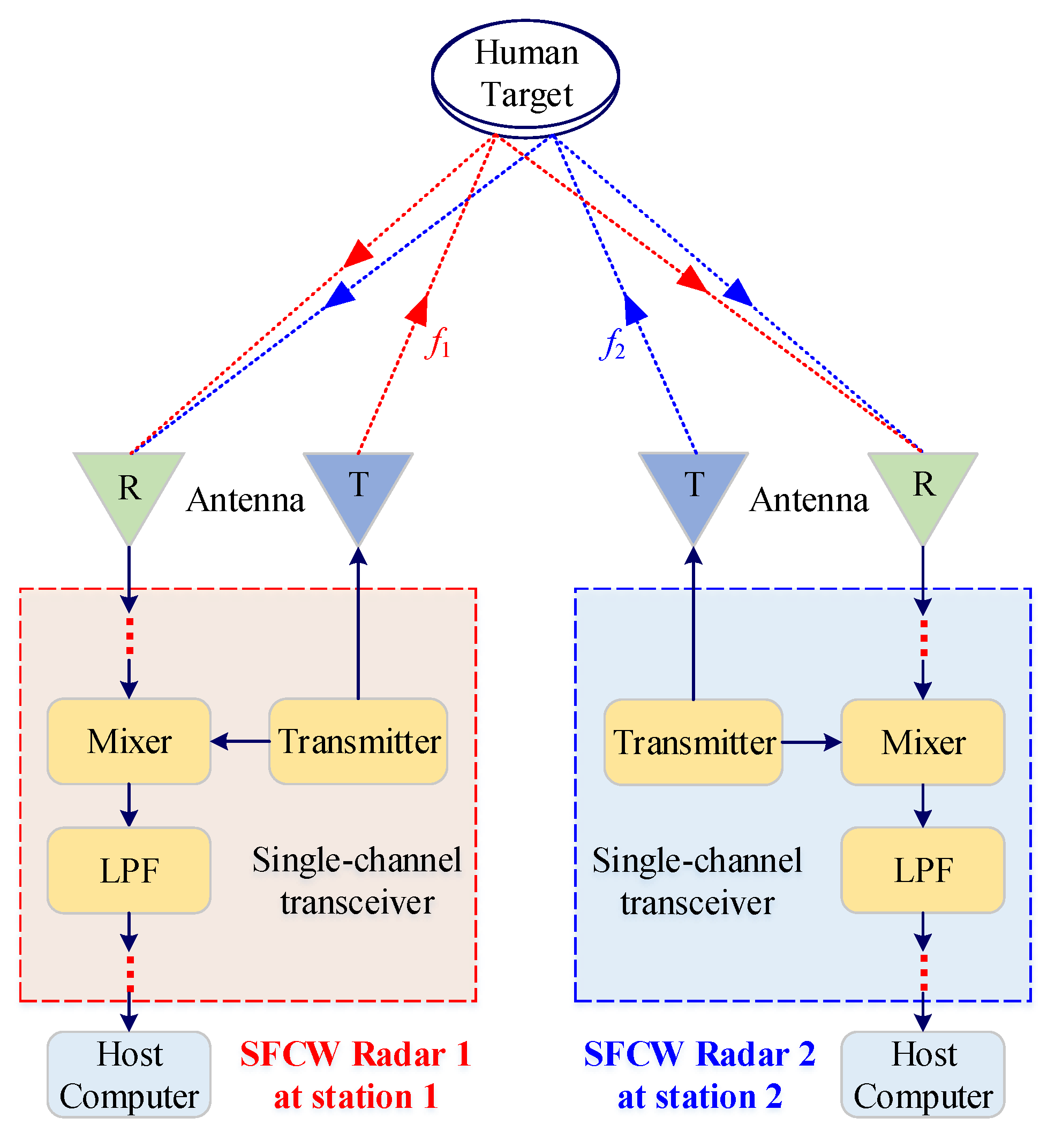
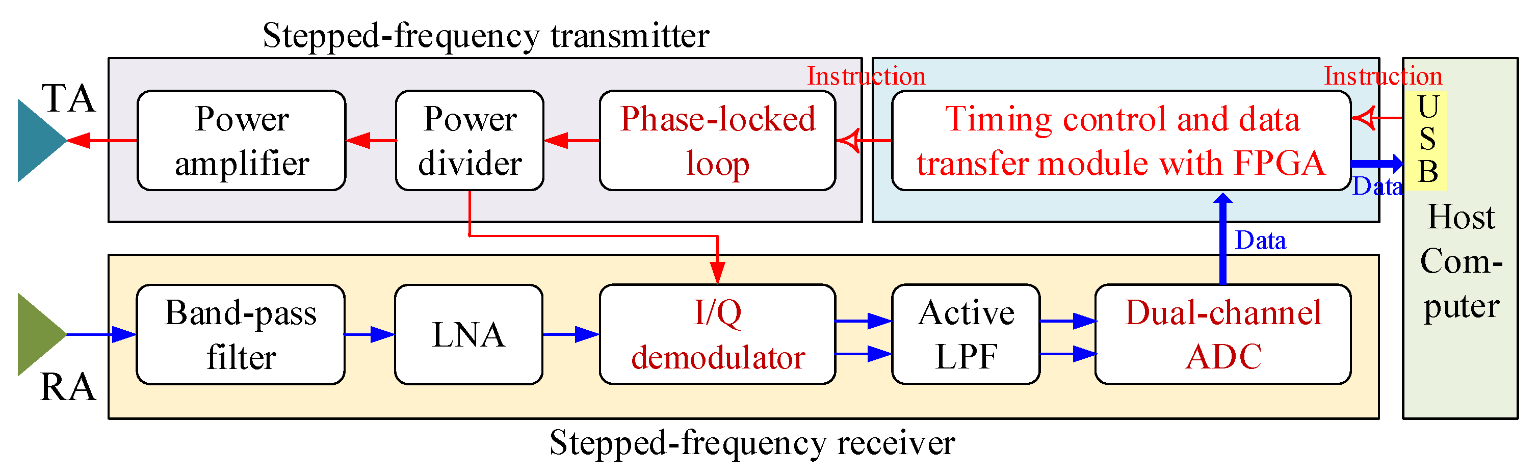
2. Dual-Station SFCW Radar
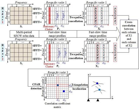
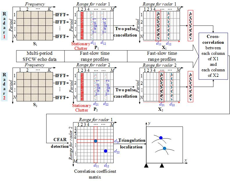
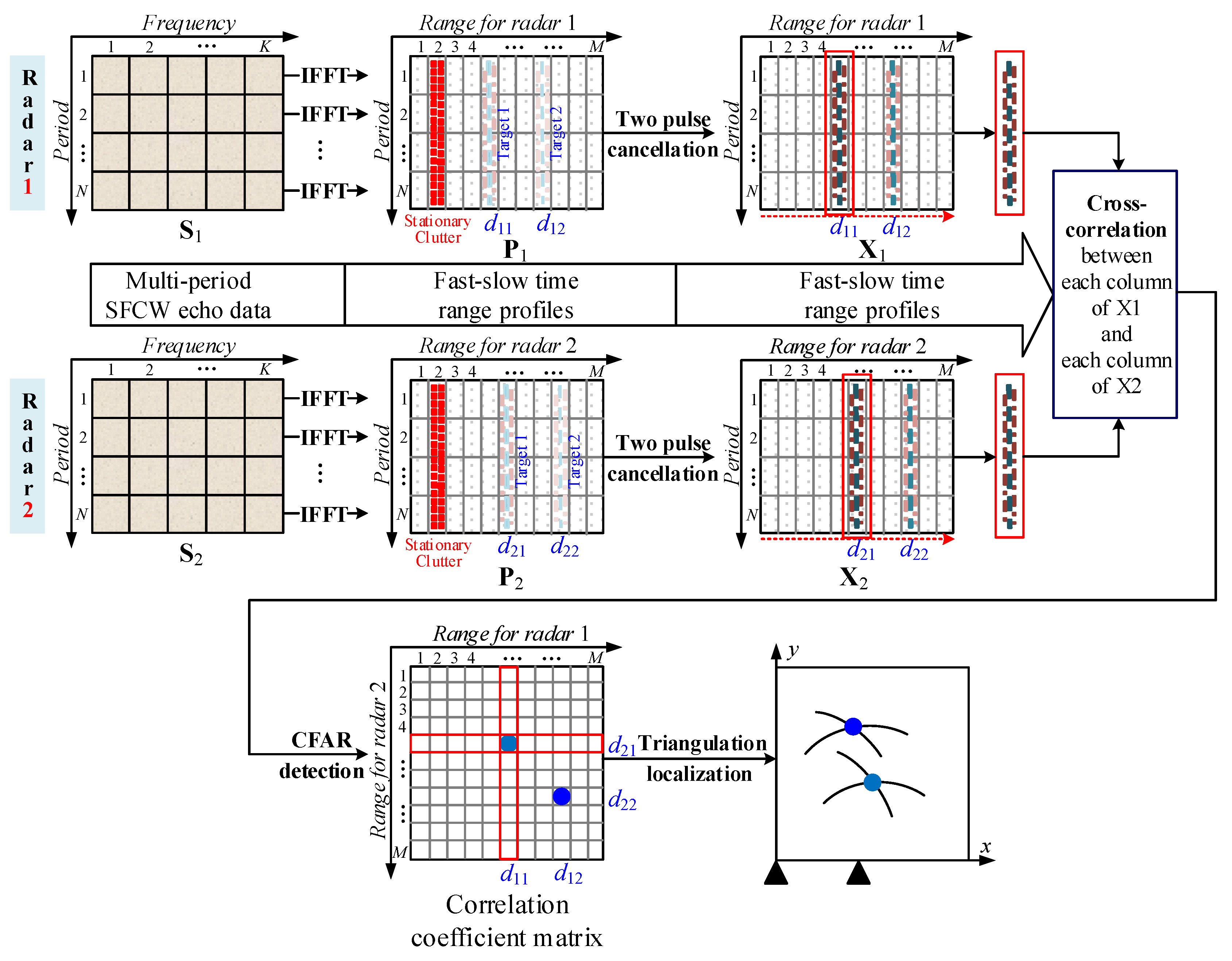
3. Dual-Station Cross-Correlation Based Detection and Localization
3.1. Signal Model
3.2. Data Preprocessing
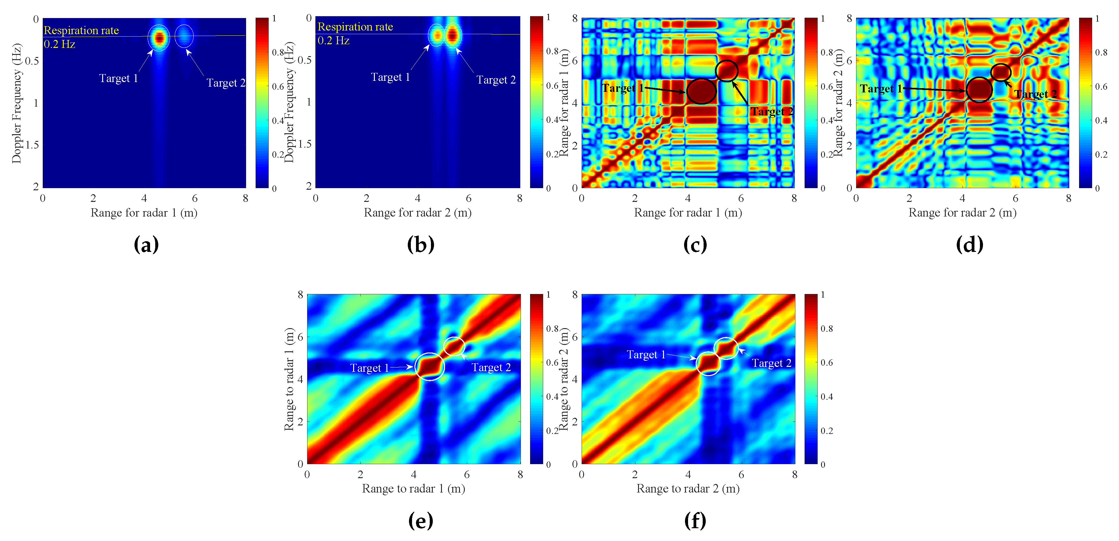
3.3. Dual-Station Cross-Correlation
3.4. Target Identification and Localization
4. Experimental Results and Discussion
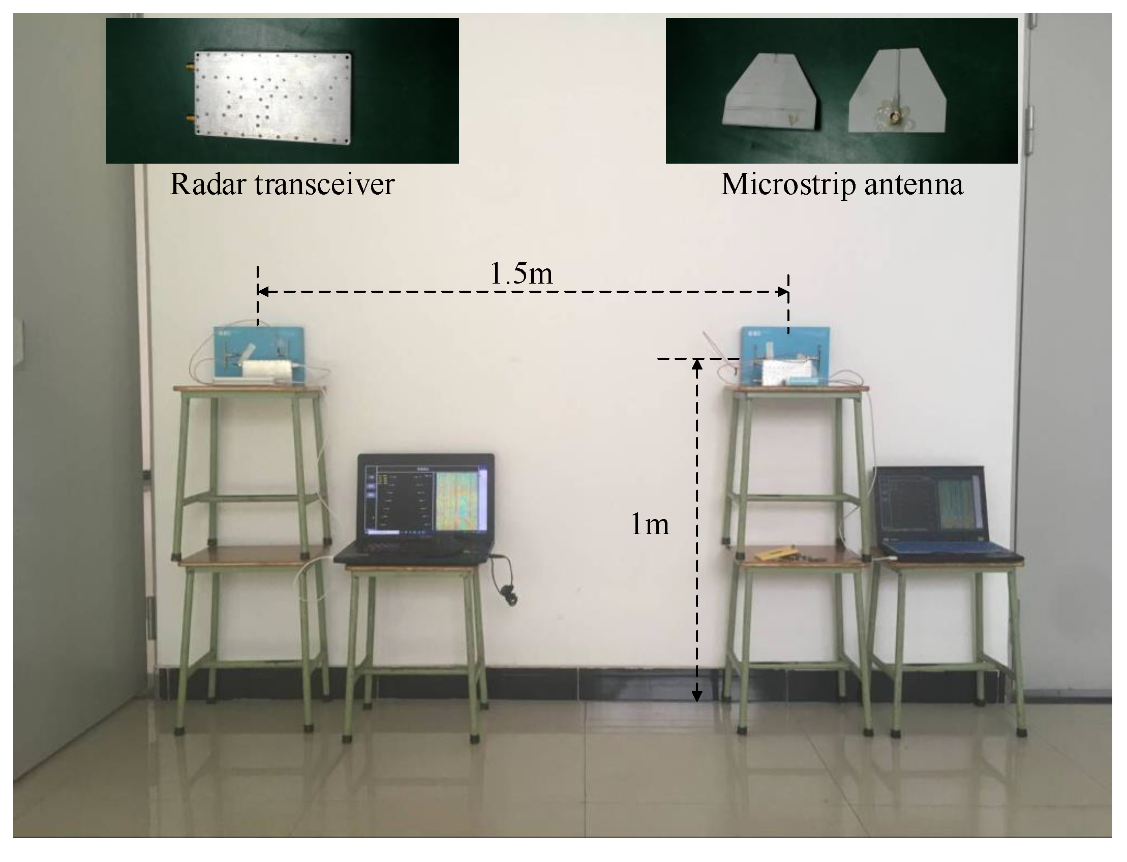
4.1. Description of Single-Channel SFCW Radar
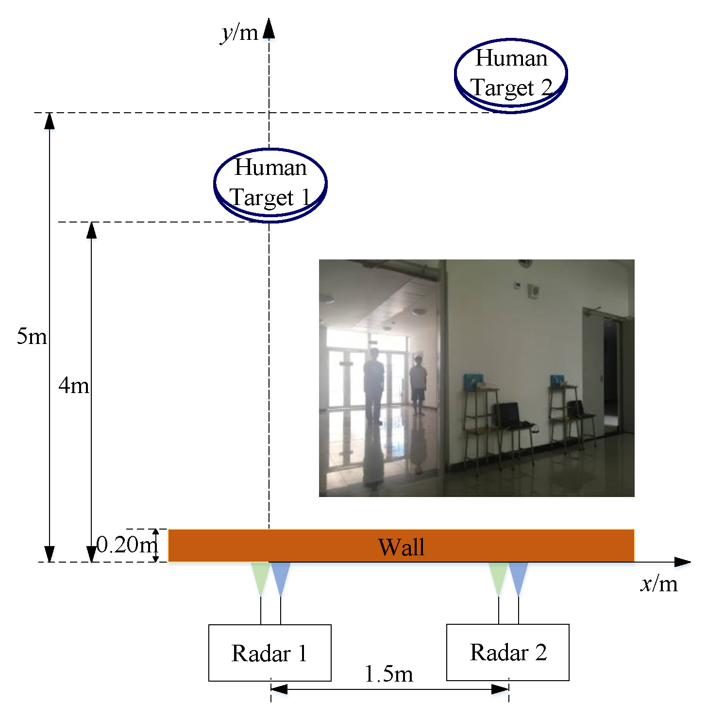
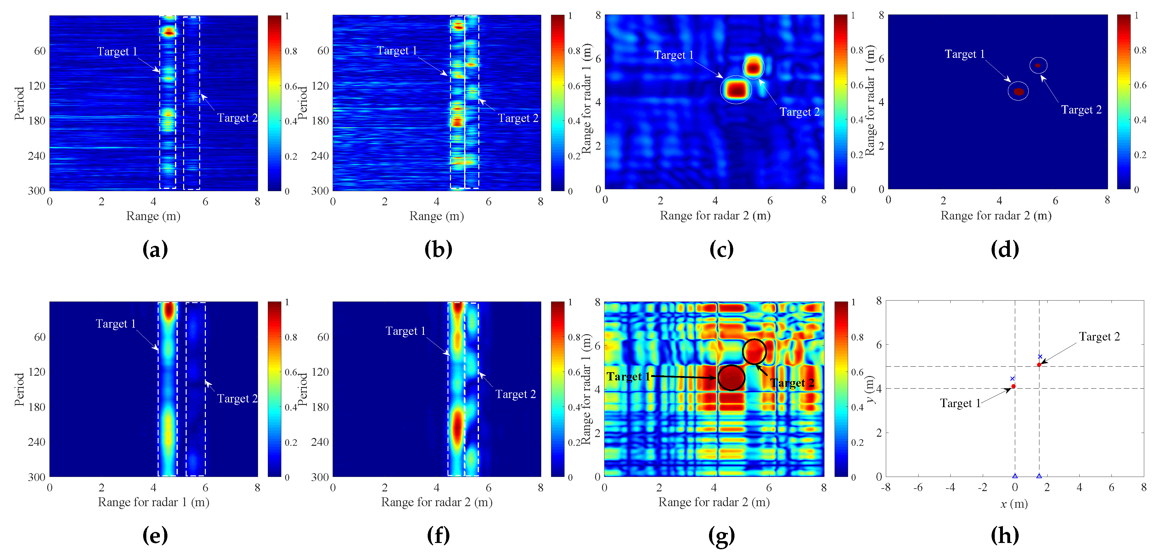
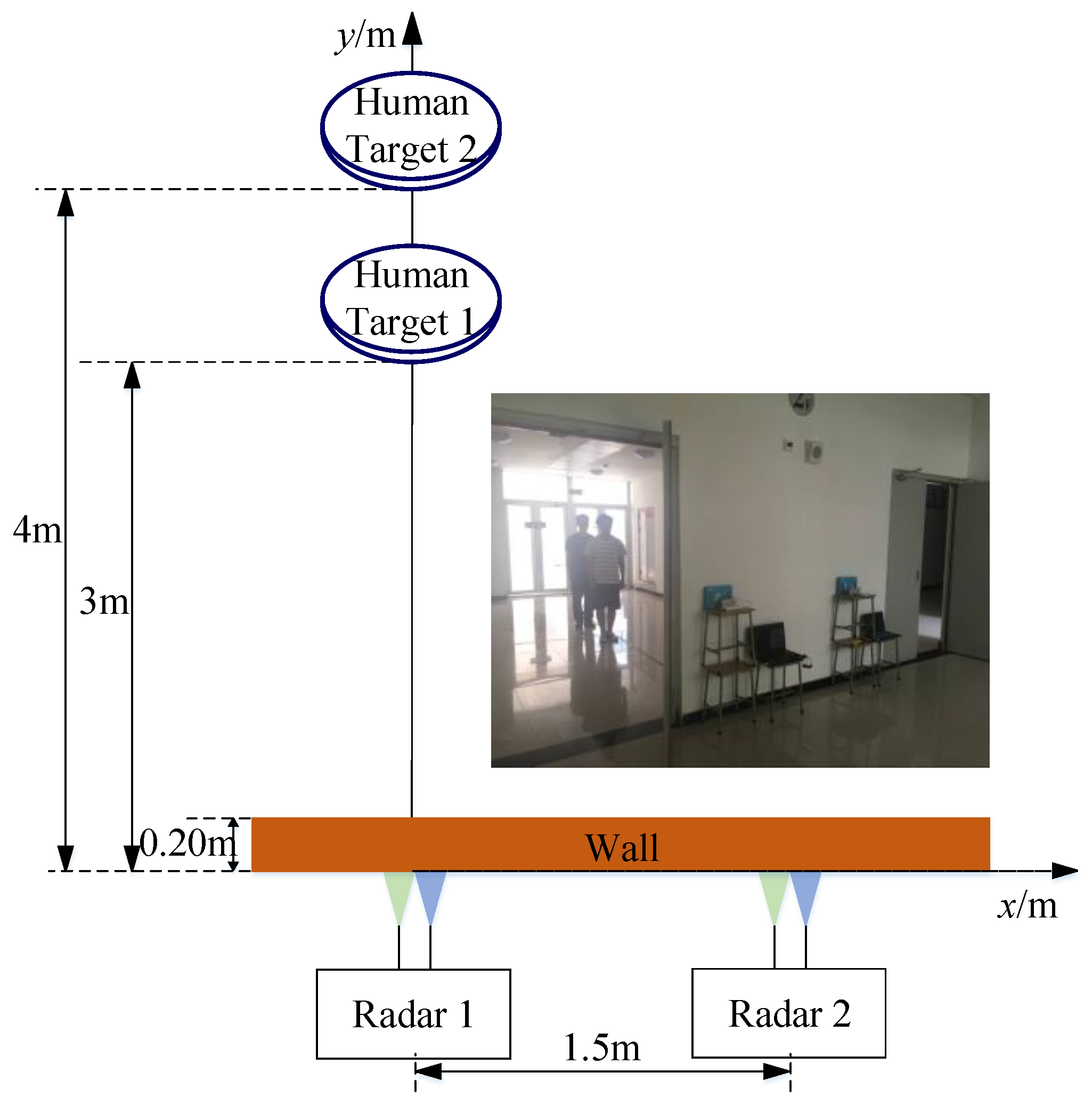
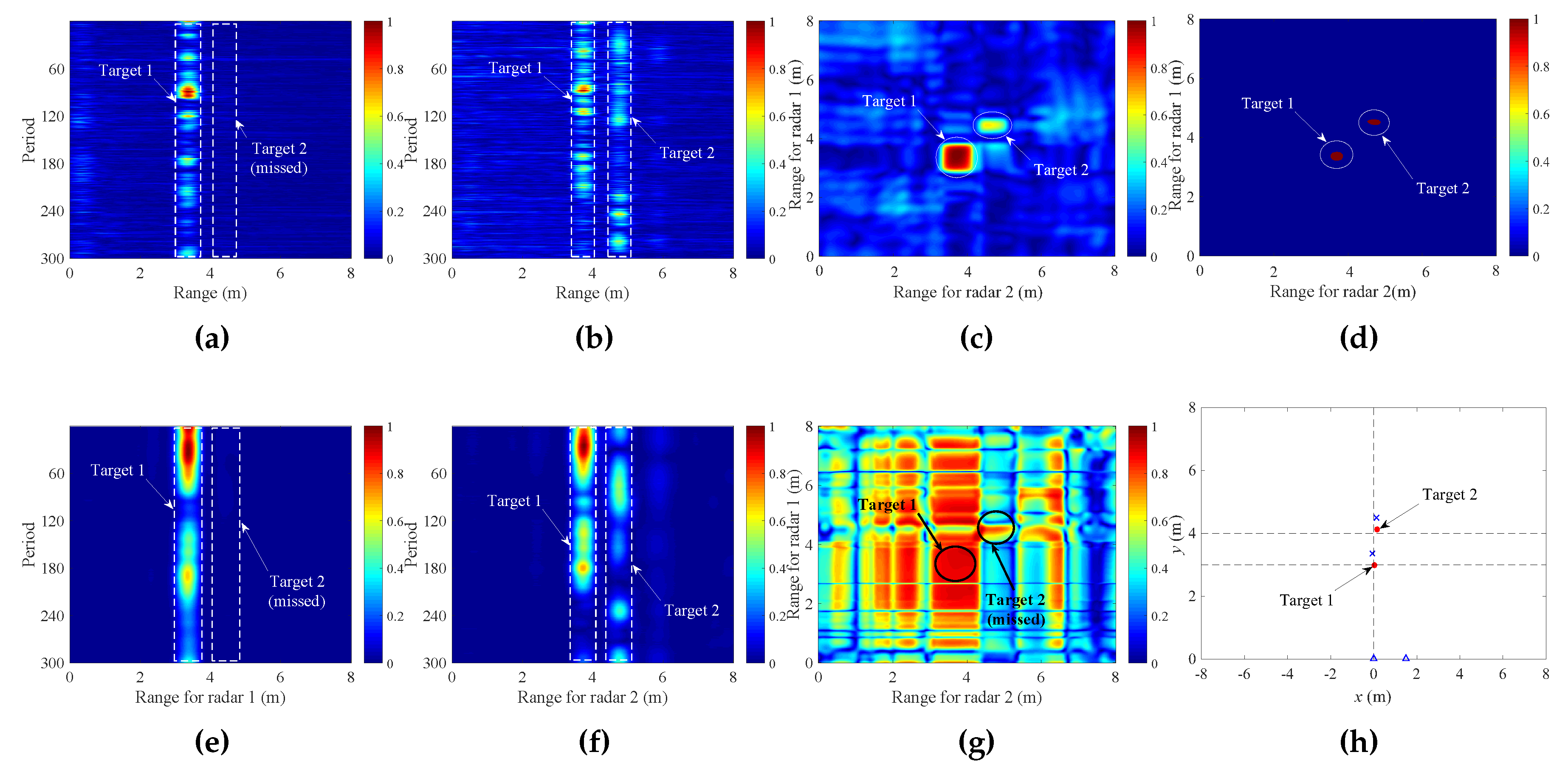
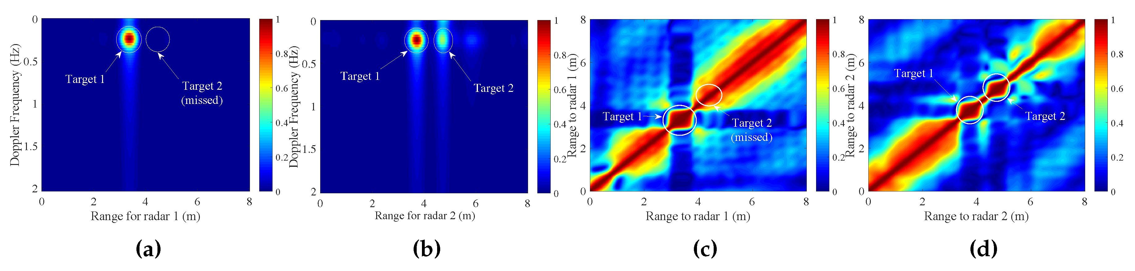
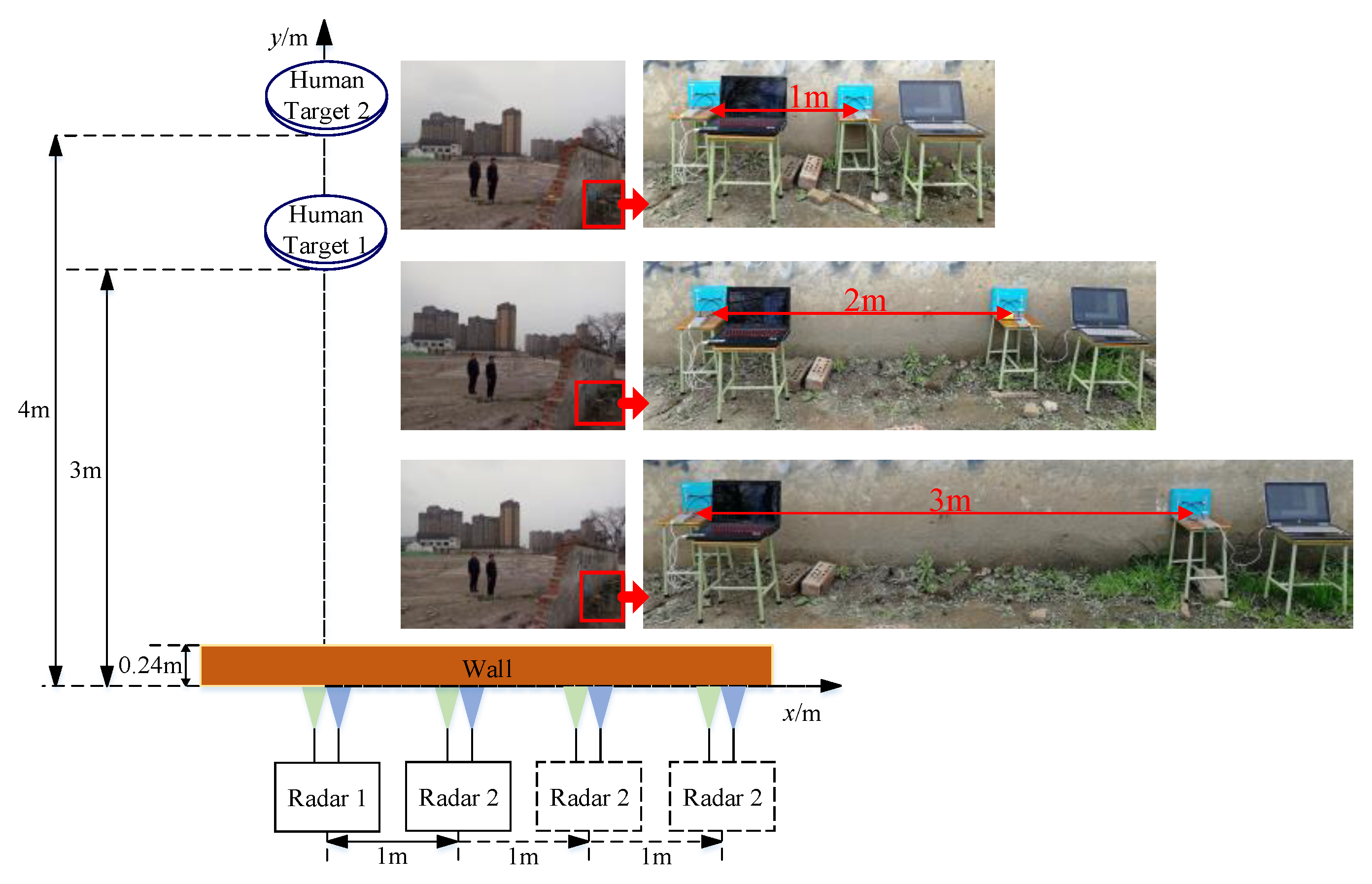
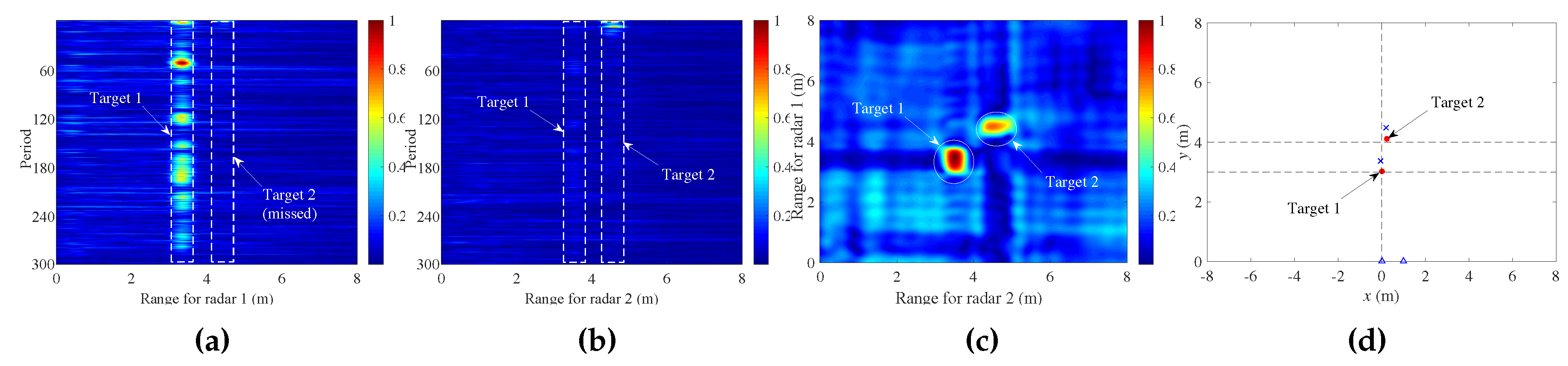
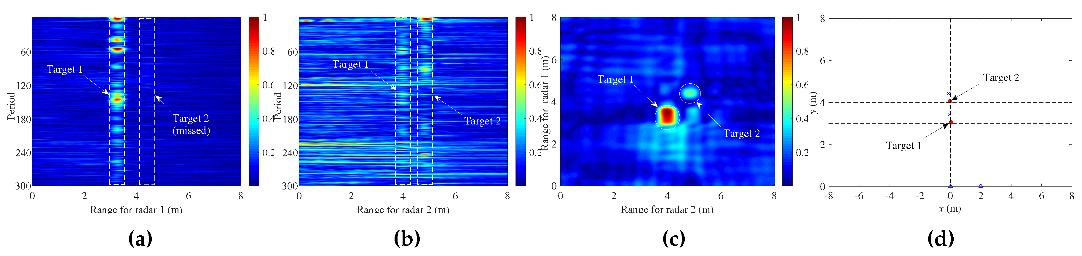
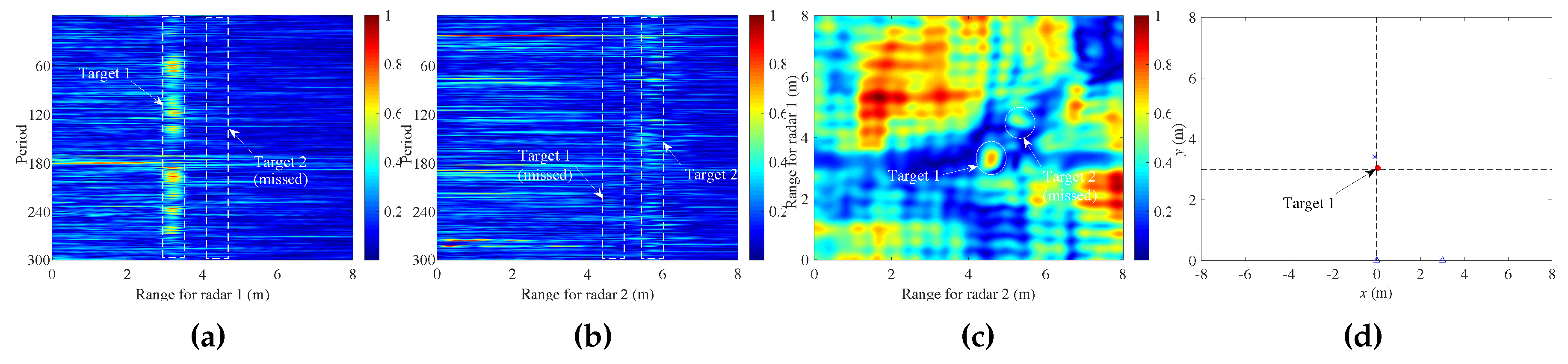
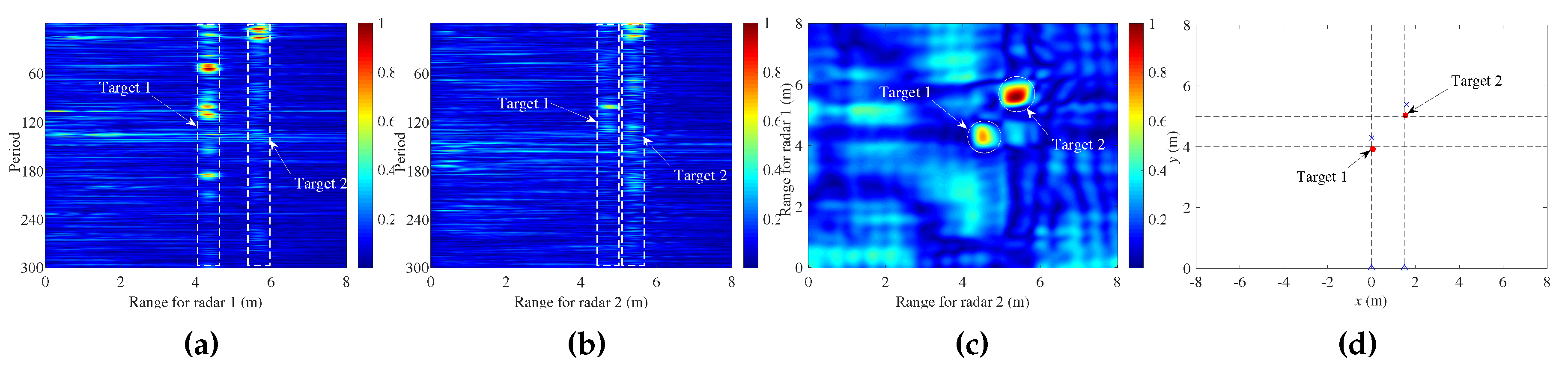
4.2. Experiments with Different Target Positions
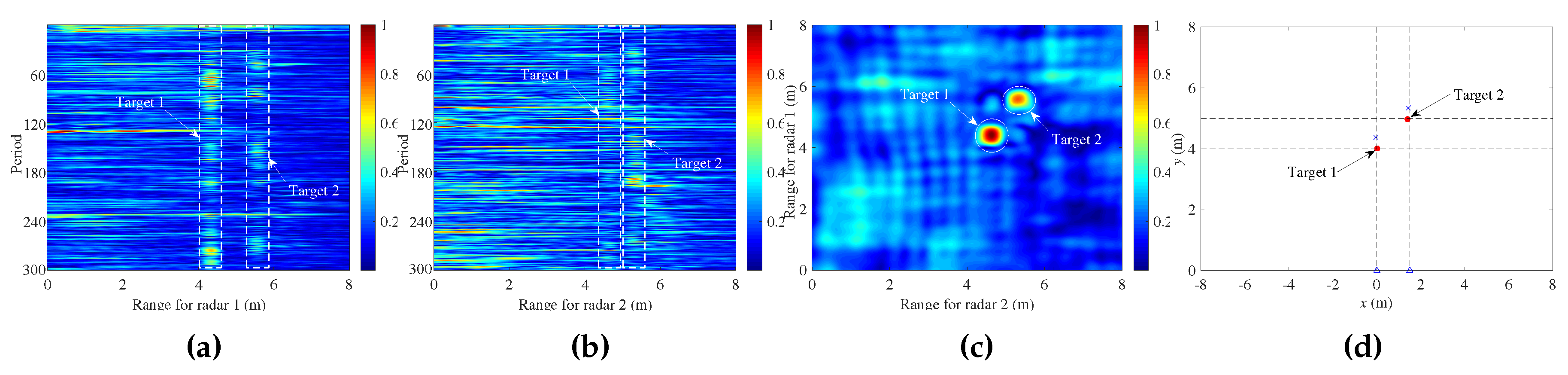
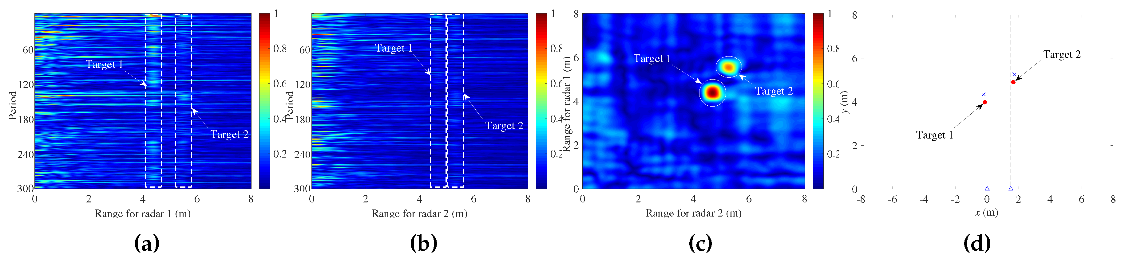
4.3. Experiments with Different Radar Locations
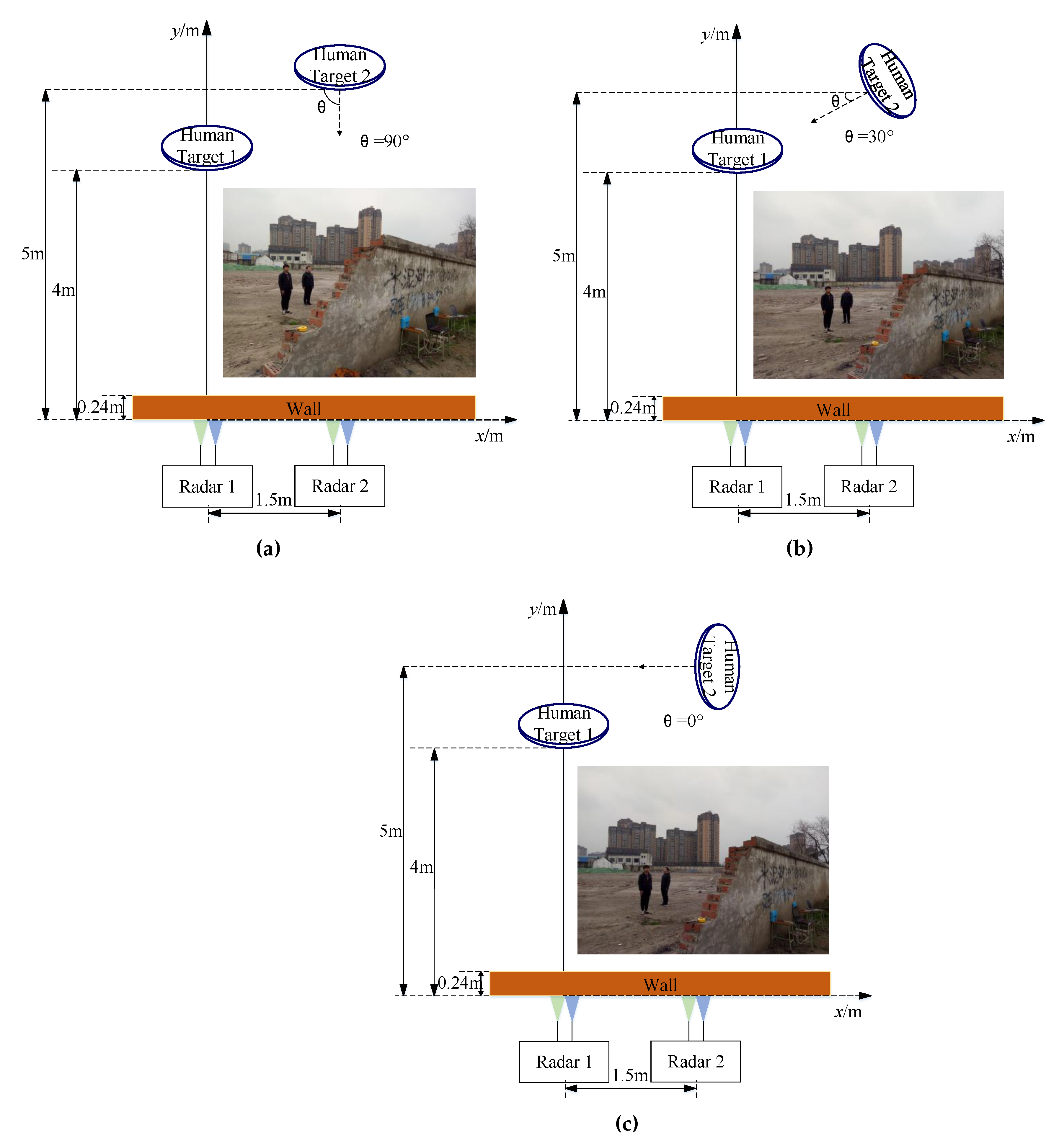
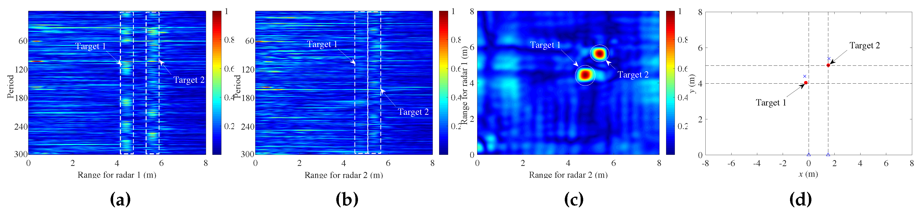
4.4. Experiments with Different Target Orientations
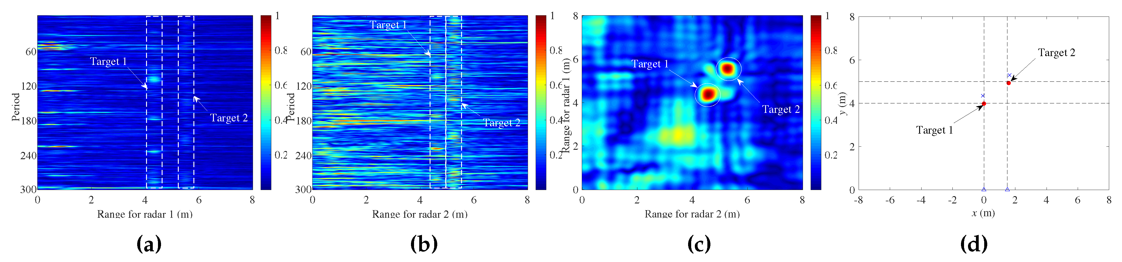
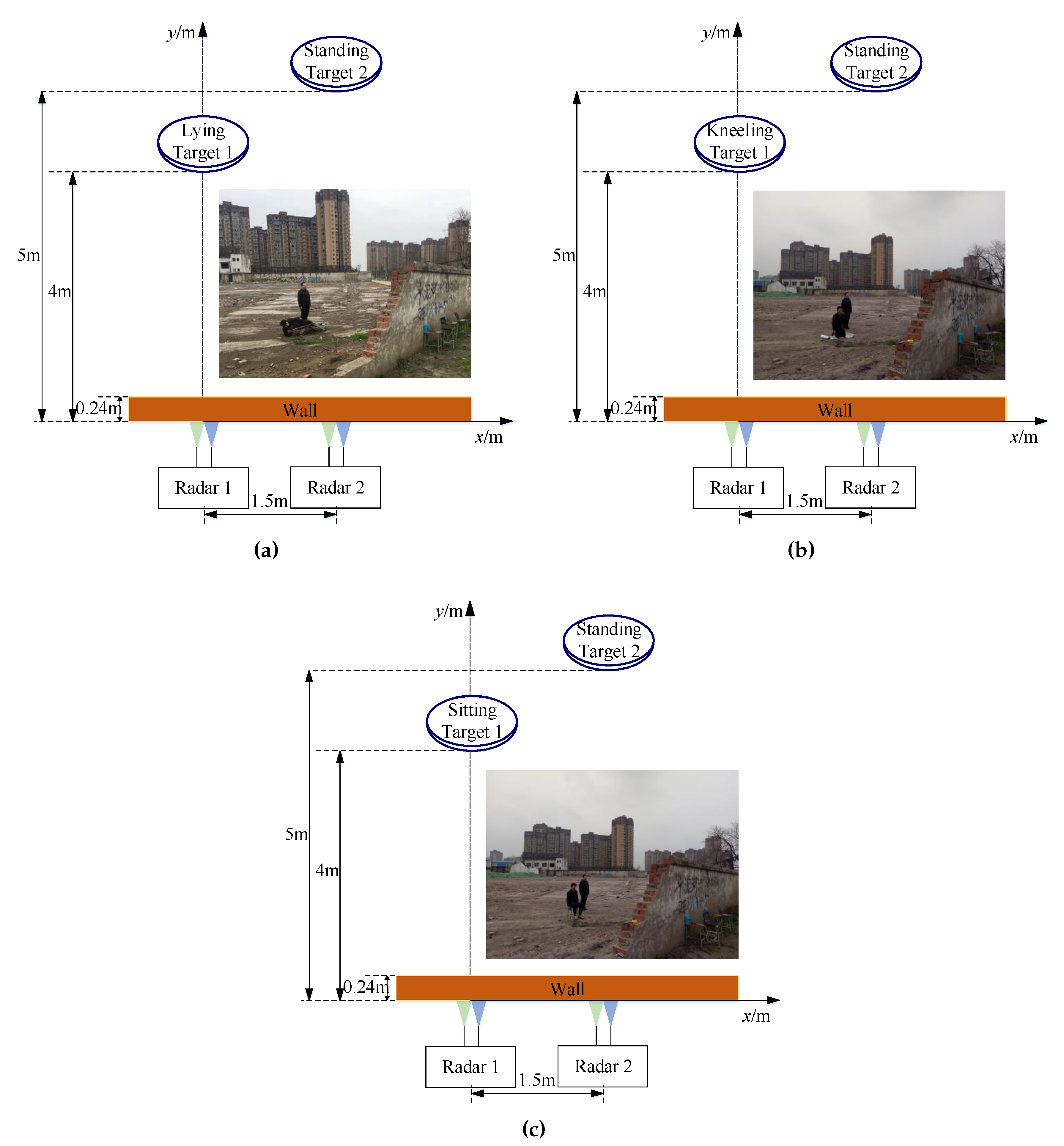
4.5. Experiments with Different Target Postures
5. Conclusions
Author Contributions
Funding
Conflicts of Interest
Abbreviations
| CFAR | Constant false alarm rate |
| FFT | Fast Fourier transform |
| FPGA | Field-programmable gate array |
| IFFT | Inverse fast Fourier transform |
| I/Q | In-phase/Quadrature |
| LNA | low-noise amplifier |
| LPF | Low-pass filter |
| MLE | Mean localization error |
| RA | Receiving antenna |
| RD | Range-Doppler |
| SF | Stepped-frequency |
| SFCW | Stepped-frequency continuous-wave |
| SNR | Signal-to-noise ratio |
| TA | Transmitting antenna |
| UWB | Ultra-wide band |
References
- Mazhar, F.; Khan, M.G.; Sällberg, B. Precise Indoor Positioning Using UWB: A Review of Methods, Algorithms and Implementations. Wirel. Pers. Commun. 2017, 97, 4467–4491. [Google Scholar] [CrossRef]
- Hu, H.B.; Lin, G.H.; He, H.; Zhang, Y.M. A Review of Research of Life Detecting Radar. Appl. Mech. Mater. 2014, 519–520, 1139–1143. [Google Scholar] [CrossRef]
- Shi, L.; Jiang, M.; Huang, L. Human status recognition method for the life detection radarbased on the harmonic model. J. Xidian Univ. 2005, 32, 179–183. [Google Scholar] [CrossRef]
- Lubecke, V.M.; Boric-Lubecke, O.; Host-Madsen, A.; Fathy, A.E. Through-the-Wall Radar Life Detection and Monitoring. In Proceedings of the 2007 IEEE/MTT-S International Microwave Symposium, Honolulu, HI, USA, 3–8 June 2007; pp. 769–772. [Google Scholar] [CrossRef]
- Lu, G.H.; Wang, J.Q.; Yang, G.S. Current state of the technology of bioradar. Foreign Med. Biomed. Eng. Fasc. 2004. [Google Scholar]
- Liu, J.; Jia, Y.; Kong, L.; Yang, X.; Liu, Q.H. MIMO through-wall radar 3-D imaging of a human body in different postures. J. Electromagn. Waves Appl. 2016, 30, 849–859. [Google Scholar] [CrossRef]
- Jia, Y.; Zhong, X.; Liu, J.; Guo, Y. Single-Side Two-Location Spotlight Imaging for Building Based on MIMO Through-Wall-Radar. Sensors 2016, 16, 1441. [Google Scholar] [CrossRef] [PubMed]
- Liu, J.; Jia, Y.; Kong, L.; Yang, X.; Liu, Q.H. Sign-Coherence-Factor-Based Suppression for Grating Lobes in Through-Wall Radar Imaging. IEEE Geosci. Remote Sens. Lett. 2016, 13, 1681–1685. [Google Scholar] [CrossRef]
- Cippitelli, E.; Fioranelli, F.; Gambi, E.; Spinsante, S. Radar and RGB-Depth Sensors for Fall Detection: A Review. IEEE Sens. J. 2017, 17, 3585–3604. [Google Scholar] [CrossRef]
- Zhang, J.; Jin, T.; He, Y.M.; Zhou, Z. A Centralized Processing Framework for Foliage Penetration Human Tracking in Multistatic Radar. Radioengineering 2016, 25, 98–105. [Google Scholar] [CrossRef]
- Caro, C.G.; Bloice, J.A. Contactless apnoea detector based on radar. Lancet 1971, 2, 959–961. [Google Scholar] [CrossRef]
- Tateishi, N.; Mase, A.; Bruskin, L.; Kogi, Y.; Ito, N.; Shirakata, T.; Yoshida, S. Microwave Measurement of Heart Beat and Analysis Using Wavelet Transform. In Proceedings of the 2007 Asia-Pacific Microwave Conference, Bangkok, Thailand, 11–14 December 2007; pp. 2151–2153. [Google Scholar] [CrossRef]
- Chen, K.M.; Huang, Y.; Zhang, J.; Norman, A. Microwave life-detection systems for searching human subjects under earthquake rubble or behind barrier. IEEE Trans. Biomed. Eng. 2000, 47, 105–114. [Google Scholar] [CrossRef] [PubMed]
- Yarovoy, A.G.; Ligthart, L.P.; Matuzas, J.; Levitas, B. UWB radar for human being detection. IEEE Aerosp. Electron. Syst. Mag. 2006, 21, 10–14. [Google Scholar] [CrossRef]
- Anitori, L.; de Jong, A.; Nennie, F. FMCW radar for life-sign detection. In Proceedings of the 2009 IEEE Radar Conference, Pasadena, CA, USA, 4–8 May 2009; pp. 1–6. [Google Scholar] [CrossRef]
- Guo, S.; Cui, G.; Kong, L.; Yang, X. An Imaging Dictionary Based Multipath Suppression Algorithm for Through-Wall Radar Imaging. IEEE Trans. Aerosp. Electron. Syst. 2018, 54, 269–283. [Google Scholar] [CrossRef]
- Guo, S.; Cui, G.; Wang, M.; Kong, L.; Yang, X. Similarity-based multipath suppression algorithm for through-wall imaging radar. IET Radar Sonar Navig. 2017, 11, 1041–1050. [Google Scholar] [CrossRef]
- Qiu, L.; Jin, T.; Lu, B.; Zhou, Z. An Isophase-Based Life Signal Extraction in Through-the-Wall Radar. IEEE Geosci. Remote Sens. Lett. 2017, 14, 193–197. [Google Scholar] [CrossRef]
- Phelan, B.R.; Ranney, K.I.; Gallagher, K.A.; Clark, J.T.; Sherbondy, K.D.; Narayanan, R.M. Design of Ultrawideband Stepped-Frequency Radar for Imaging of Obscured Targets. IEEE Sens. J. 2017, 17, 4435–4446. [Google Scholar] [CrossRef]
- Yılmaz, B.; Özdemir, C. A detection and localization algorithm for moving targets behind walls based on one transmitter-two receiver configuration. Microw. Opt. Technol. Lett. 2017, 59, 1252–1259. [Google Scholar] [CrossRef]
- Jia, Y.; Kong, L.; Yang, X.; Wang, K. Through-wall-radar localization for stationary human based on life-sign detection. In Proceedings of the 2013 IEEE Radar Conference (RadarCon13), Ottawa, ON, Canada, 29 April–3 May 2013; pp. 1–4. [Google Scholar] [CrossRef]
- Zhang, Y.; Chen, F.; Xue, H.; Li, Z.; An, Q.; Wang, J. Detection and Identification of Multiple Stationary Human Targets Via Bio-Radar Based on the Cross-Correlation Method. Sensors 2016, 16, 1793. [Google Scholar] [CrossRef] [PubMed]
- Yan, S.; Kong, L.; Yang, X.; Zhou, Y. Life detection based on cross-correlation analysis. In Proceedings of the 2011 IEEE CIE International Conference on Radar, Chengdu, China, 24–27 October 2011; Volume 2, pp. 1346–1348. [Google Scholar] [CrossRef]
- Conte, E.; De Maio, A.; Ricci, G. Recursive estimation of the covariance matrix of a compound-Gaussian process and its application to adaptive CFAR detection. IEEE Trans. Signal Process. 2002, 50, 1908–1915. [Google Scholar] [CrossRef]
- Xu, S.W.; Shui, P.L. Range-spread target detection in white Gaussian noise via two-dimensional non-linear shrinkage map and geometric average integration. IET Radar Sonar Navig. 2012, 6, 90–98. [Google Scholar] [CrossRef]


| Parameters | Value |
|---|---|
| Frequency number | 301 |
| Starting frequency | 1.6 GHz |
| Ending frequency | 2.2 GHz |
| Frequency step | 2 MHz |
| Duration time of each frequency | 100 μs |
| Bandwidth | 600 MHz |
| Pulse repetition interval | 30.1 ms |
| Radiation power | 18 dBm |
| Sampling rate of ADC | 250 KHz |
| Sampling bit number of ADC | 14 bits |
| Parameters | Value |
|---|---|
| 3 dB beamwidth in azimuth at 1.9 GHz (E plane) | |
| 3 dB beamwidth in elevation at 1.9 GHz (H plane) | |
| Gain | >4 dB |
| Voltage standing wave ratio | <2 |
| Size: maximum width | 75 mm |
| Size: height | 47 mm |
| Size: thickness | 3 mm |
| Experiment 2.1 | Experiment 2.2 | Experiment 2.3 | |
|---|---|---|---|
| Extracted coordinates of Target 1 | (0.02 m, 3.02 m) | (0.04 m, 3.05 m) | (0.04 m, 3.04 m) |
| Extracted coordinates of Target 2 | (0.22 m, 4.11 m) | (−0.03 m, 4.06 m) | Missed detection |
| MLE | 0.14 m | 0.07 m | N/A |
| Experiment 3.1 | Experiment 3.2 | Experiment 3.3 | |
|---|---|---|---|
| Extracted coordinates of Target 1 | (0.06 m, 3.92 m) | (0 m, 3.98 m) | (−0.11 m, 3.93 m) |
| Extracted coordinates of Target 2 | (1.54 m, 5.03 m) | (1.58 m, 4.94 m) | (1.43 m, 5.04 m) |
| MLE | 0.08 m | 0.06 m | 0.11 m |
| Experiment 4.1 | Experiment 4.2 | Experiment 4.3 | |
|---|---|---|---|
| Extracted coordinates of Target 1 | (0.02 m, 4.01 m) | (−0.14 m, 3.99 m) | (−0.06 m, 4.02 m) |
| Extracted coordinates of Target 2 | (1.39 m, 4.97 m) | (1.66 m, 4.91 m) | (1.69 m, 4.94 m) |
| MLE | 0.07 m | 0.16 m | 0.13 m |
© 2019 by the authors. Licensee MDPI, Basel, Switzerland. This article is an open access article distributed under the terms and conditions of the Creative Commons Attribution (CC BY) license (http://creativecommons.org/licenses/by/4.0/).
Share and Cite
Jia, Y.; Guo, Y.; Yan, C.; Sheng, H.; Cui, G.; Zhong, X. Detection and Localization for Multiple Stationary Human Targets Based on Cross-Correlation of Dual-Station SFCW Radars. Remote Sens. 2019, 11, 1428. https://doi.org/10.3390/rs11121428
Jia Y, Guo Y, Yan C, Sheng H, Cui G, Zhong X. Detection and Localization for Multiple Stationary Human Targets Based on Cross-Correlation of Dual-Station SFCW Radars. Remote Sensing. 2019; 11(12):1428. https://doi.org/10.3390/rs11121428
Chicago/Turabian StyleJia, Yong, Yong Guo, Chao Yan, Haoxuan Sheng, Guolong Cui, and Xiaoling Zhong. 2019. "Detection and Localization for Multiple Stationary Human Targets Based on Cross-Correlation of Dual-Station SFCW Radars" Remote Sensing 11, no. 12: 1428. https://doi.org/10.3390/rs11121428
APA StyleJia, Y., Guo, Y., Yan, C., Sheng, H., Cui, G., & Zhong, X. (2019). Detection and Localization for Multiple Stationary Human Targets Based on Cross-Correlation of Dual-Station SFCW Radars. Remote Sensing, 11(12), 1428. https://doi.org/10.3390/rs11121428