Abstract
Avoiding collisions with other objects is one of the most basic safety tasks undertaken in the operation of floating vehicles. Addressing this challenge is essential, especially during unmanned vehicle navigation processes in autonomous missions. This paper provides an empirical analysis of the surface target detection possibilities in a water environment, which can be used for the future development of tracking and anti-collision systems for autonomous surface vehicles (ASV). The research focuses on identifying the detection ranges and the field of view for various surface targets. Typical objects that could be met in the water environment were analyzed, including a boat and floating objects. This study describes the challenges of implementing automotive radar sensors for anti-collision tasks in a water environment from the perspective of target detection with the application for small ASV performing tasks on the lake.
1. Introduction
Unmanned vehicle technology and surface robots have been rapidly developed over the past few years. These systems supersede previously used methods for exploring the underwater parts of the Earth. Trends in the development of unmanned systems point clearly towards the future execution of underwater tasks, including hydrographical surveys, using the direct nearness to the bottom by autonomous surface vehicles (ASVs). The use of ASVs can supplement or replace many hours of measurements conducted by teams of hydrographers, especially in remote areas. Nowadays ASVs are used in many scientific and commercial implementations. They can be met for example in the army for reconnaissance and combat purposes, they serve as research units providing information on various aspects of the aquatic environment, and as carriers of measuring equipment for the inventory of watercourses and reservoirs.
The main tasks and challenges for ASVs depend on the kind of mission performed. However, some of them are common for all approaches and can be treated as a basis for specialized tasks. Among these for sure is the navigation itself and mission control with the use of telemetry, as the most basic priority for ship navigation is its safety. The navigation process can be however understood variably in different applications. In some approaches and applications, like simultaneous localization and mapping (SLAM), the term navigation also means getting information about the surrounding area. Various sensors for this purpose can be employed like 3D laser scanners [1]. These aspects, generally referred to as navigation, can also be found for example in [2,3], where lidar is also used for navigation purposes. Some authors also include the path planning process into navigation itself, while the others threat dynamic path planning as more collision avoidance tasks. A fine survey on this can be found for example in [4,5].
One of the most important safety tasks during the operation of USV is avoiding collisions. It might be treated more as a situation awareness task and not navigation itself. Nevertheless the process of automating collision avoidance is always a key issue for unmanned vehicles, as it directly influences its safety and ability to perform a mission. Maneuvering for anti-collision purposes consists of several steps, including target detection, movement vector estimation, identifying the correct collision avoidance maneuver based on navigation obstacles and other moving ships, and finally implementation. The first step is always to get information about the surrounding environment, which is done by on-board sensors, processing the information for the anti-collision module. The most obvious sensors for this case of robotic application are range finders or in more advanced applications laser scanners [6]. The use of other sensors require implementation of advanced fusion algorithms, like in [7], where it is proposed to enhance the laser system with cameras. The information gathered from sensors is then processed by the anti-collision system to find the most suitable track. A fine survey on this, together with the review of sensors used for anti-collision in USV can be found for example in [8]. There are also some examples in literature for using radar sensor as a core for anti-collision, mostly in maritime ASV. Such approach can be found for example in [9] or [10] in which typical pulse X-band radar is used or in [11] in which frequency-modulated continuous-wave radar (FMCW) X-band radar is proposed (it might also be an option in [9]). These approaches are suitable for maritime application, however typical marine sensors may be too big for the smaller USV in inland waters. The new contribution of this research is to indicate a new approach, which is the implementation of autonomous radar for water vehicles.
In this paper, we propose a new idea, to implement an automotive 3D radar sensor in the autonomous navigation system of an ASV. The proposed approach is a combination of the traditional approach met in the waters, namely the use of radar sensors, and the approach known from roads in which radars are used for car collision systems. This sensor works with a fixed antenna, unlike the traditional rotated radar antennas. The first step in target tracking by radar is target detection, especially small targets in close range observation, which is essential in restricted waters.
In this study, experiments were conducted in real inland waterway conditions with an automotive 3D radar sensor mounted on an ASV owned by Marine Technology Ltd., named HydroDron. The goal was to use the collected data to address the autonomous collision avoidance problem for future intelligent ASV systems. This will be the basis for the implementation of such an innovative system for real-time ASV missions.
It should be pointed out here, that the sensor and system proposed in this study is suitable for small ASVs performing their duties in inland water or in restricted harbor areas. The detection range of this sensor is too small to be useful for marine vessels and therefore marine applications are beyond the scope of this paper. The use cases covered by this research assume that the ASV is performing her autonomic mission (likely hydrographic, but can be any other), navigating in a lake, river or near-coast waters. Hydrographic surveys are often performed in the areas near recreational or fishing sites. The goal of the research was to present detection possibilities for typical objects that could also be met in these areas, which includes not only boats, but also other floating objects.
The paper is organized as follows—in Section 2 the idea and theory of the radar used is presented; Section 3 gives the details of the anti-collision system concept together with the review of related works and papers; Section 4 provides a description of the research; and Section 5 includes the conclusions.
2. Automotive Radar Sensors
Automotive radar is used to detect objects in the vicinity of a vehicle. The sensor consists of a transmitter and receiver. The transmitter emits radio waves that return to the receiver after bouncing from the target. By controlling the direction in which radio waves are sent and received, it is possible to determine the distance, speed, and direction of the objects.
There are two basic methods for measuring distances using radar. The first is known as the direct propagation method, which measures the delay associated with receiving the reflected signal. The delay is correlated with the distance of the reflecting object depending on the speed of light and period and the transmission and reception of waves. The second method is known as the indirect propagation method. In the case of indirect propagation, a modulated frequency is sent and received, and the frequency difference can be used to directly determine the distance and relative velocity of the object. This requires controllable antennas that can be automatically routed or receive signals simultaneously from several different directions.
2.1. FMCW Radars
There are two types of automotive radars, pulse radar or radar with continuous wave. The latter is termed the frequency-modulated continuous-wave radar (FMCW). The pulse radar sends short pulses and determines the distance by measuring the delay time between the transmitted and feedback signal [12]. The FMCW radar continuously sends a linearly modulated signal and determines the distance based on the difference in the transmitted and received frequencies, as shown in Figure 1.
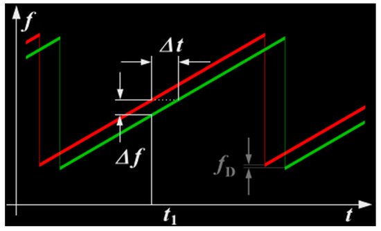
Figure 1.
Ranging with an FMCW system [13].
Measuring very short time periods in electronics is difficult, which means that building a good resolution pulse radar is very expensive. However, the resulting resolution is relatively precise, e.g., the FMCW radar can easily have a resolution of 0.5 m [14].
Impulse radars are blind at short distances—for example, the 50–100 m in front of the radar is usually a blind spot. FMCW radars do not have this problem. However, for long-range targets, the pulse radar is better due to the narrower bandwidth and less noise.
In both methods, if the target is moving, the motion creates a Doppler shift in the frequency of the transmitted radar waves. This is an additional advantage for the impulse radar because it can also measure the relative target speed. In the FMCW radar, this is a problem because the distance is measured by measuring the frequency difference between the transmitted and received radar waves, and each additional frequency offset caused by the Doppler effect of the moving target "shifts" the measured distance of the object. To remedy this problem, FMCW radar systems use several different modulation schemes, including modulation with increasing frequency and frequency reduction. If these offsets are not alleviated by algorithms or have very fast frequency changes, this effect may cause the appearance of ghost targets on the FMCW radar [15].
Automotive radars are divided into three categories—long-range radar (LRR), medium range radar (MRR), and short-range radar (SRR). LRR is used to measure the distance and speed of other vehicles, MRR is used in the wider field of view, and SRR is used to detect objects near the vehicle. Two main frequency bands are used in the automotive radar systems—24 GHz and 77 GHz [16,17].
SRR for vehicles uses 24 GHz frequency because the band can detect objects at short and medium distances. A 24 GHz radar is also used to detect an object that can be obstructed or is located very close. Radar systems with the same repeatability can also be used to detect dead spots, which directly involves avoiding collisions. SRR sensors are not used to measure the angle of the detected objects and have a very wide side coverage. Usually, they are operated in pulse mode or in continuous wave mode. Small range radars require a controllable antenna with a large scan angle, creating a wide field of view [18].
While difficult to implement, LRR uses the higher permitted transmission power (77 GHz) to obtain better performance. It is easier to develop 24 GHz bands, but more difficult to integrate such radars systems into the vehicle due to their larger size. In addition, these sensors work with the same performance as the 77 GHz radars but with three times larger antennas. Therefore, the 77 GHz radar is smaller and, in contrast to the 24 GHz radar, is easier to integrate with a vehicle at a lesser cost. An additional and undeniable advantage of the wider 77 GHz band is that it provides drivers with a better resolution of objects by providing greater accuracy. The detection and reaction to the presence of both large and small objects are possible due to the clever signal processing. In the case of LRR, a higher resolution is also provided for a more limited scanning range, which requires a larger number of directional antennas [16,17].
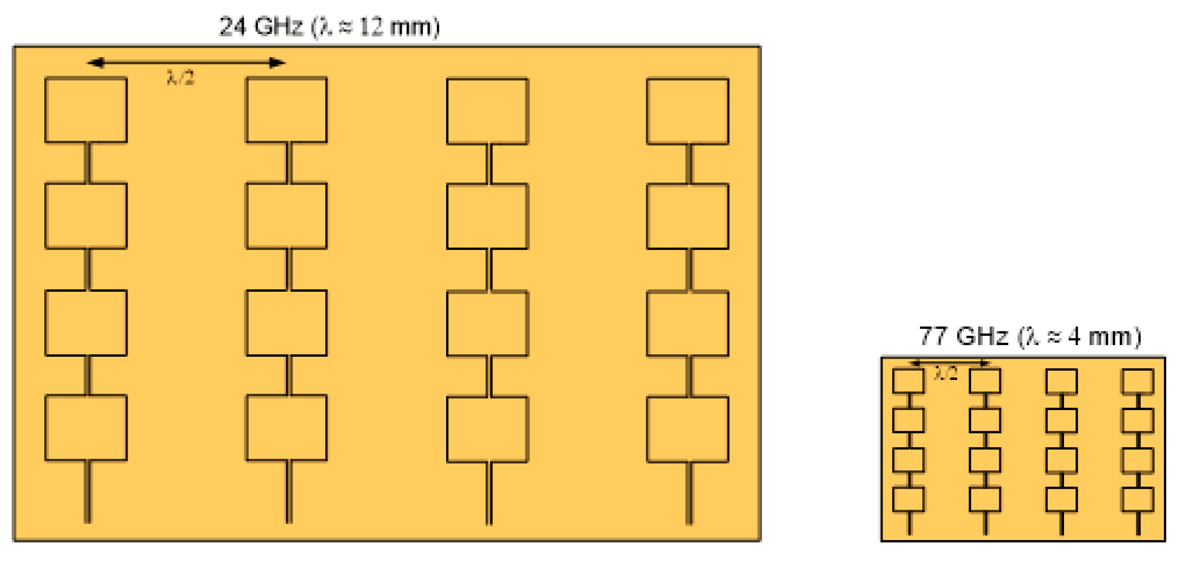
In the 77–81 GHz range, bandwidths up to 4 GHz are available, while the bandwidth available in the 24 GHz band is 200 MHz. The difference between the frequency of the signal emitted by the transmitter and the frequency of the received reflected signal is linearly dependent on the distance from the transmitter to the object. The accuracy of measuring this distance and resolution are important. The resolution is understood as the minimum distance between the objects so that they can be distinguished as different. The transition from 24 GHz to 77 GHz results in a 20 times better performance in terms of resolution and accuracy. The resolution of the 77 GHz radar range can reach 4 cm. For comparison, the 24 GHz radar achieves a resolution of 75 cm. Therefore, the advantage of the 77 GHz system is that it can detect objects that are at a short distance away from each other. Finally, the wavelength of 77 GHz signals is a third the frequency of the 24 GHz system, which enables significantly smaller modules in the spatially limited areas of the vehicle. The relative antenna sizes are shown in Figure 2.

Figure 2.
Antenna sizes for 24 GHz (left) and 77 GHz (right) radar systems [19].
Figure 3 shows the range and width of coverage of SRR, MRR, and LRR. LRR can detect objects in a wide area and can cover a range from 10 to 150 m at a beam width of 10°. MRR can cover a range up to 50 m with a beam width of 30°. In contrast, SRR can be used to track objects within a distance of 20 m from the vehicle with a beam width of 60° [20,21,22].
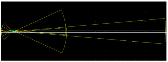
Figure 3.
The range and width of coverage of short-range radar, medium-range radar and long-range radar [19].
2.2. Radar Used in this Study
The specifications of the radar used in this study are presented in Table 1. It is a 3D UMRR 42HD automotive radar with a 24 GHz microwave sensor. The type 42 antenna has a wide field of view. The sensor is a 24 GHz 3D/UHD radar for motion management and is able to operate under adverse conditions, measuring in parallel parameters such as angle, radial speed, range, and reflectivity. It is usually used as a standalone radar for detecting approaching and receding motion. More details on the sensor used can be found in [23].

Table 1.
Specifications of the UMRR 0C Type 42 anti-collision radar.
3. Sensors for ASV Autonomous Anti-collision
As it was said, the anti-collision systems in ASVs are part of the wider concept which aims to provide tools for the safe and reliable navigation of vessels. One of the key elements of such a systems are the sensors, which provide data about the environment for further processing.
3.1. Situation Awarness Systems for ASV
Previous research has addressed the various aspects of navigation of unmanned vehicles. Video data and LiDAR fusion are described in [24]. In [25], an algorithm using LiDAR and a camera for detecting and tracking surface obstacles using the Kalman filter is presented. The legal aspects of ASV navigation, including anti-collision, are described in [26]. An approach using artificial neural networks (ANN) to solve the ASV anti-collision problem is presented in [27,28,29], where ANN was used to control the autonomous robot. The 3D mobile (3D LiDAR) and GNSS applied to autonomous car navigation was presented in [30].
One of a few attempts to use both radar and LiDAR in the navigation of mobile robots was described in [31,32,33], which also highlighted new development directions for land mapping based on radar and LiDAR. An approach using radar and LiDAR fusion to detect obstacles was taken in [34], an attempt to replace the radar with LiDAR was shown in [35] and the aspects of obstacle sensing by synthetic aperture radar interferometry was presented in [36]. An interesting approach of the anti-collision system for ASV is described in [37] in which the gathering of situational awareness relies on GPS and AIS.
Target detection in close range observation is very important to provide the next step in ASV navigation, which can be achieved by developing an advanced fast filter to track targets at a close range using automotive 3D radar. Neural solutions for radar target tracking by maritime navigation radar have been previously described by the authors of this study [38,39].
3.2. Anticollision Based on Radar Systems
As it was mentioned in the introduction, there are also several examples in literature of using radar target detection and tracking for the anti-collision of ASV. These examples can be found for example in [9,10,11], but also in [40] in which the anti-collision system based on the sensors traditionally used on maritime ships is presented.
A radar sensor is a commonly used device for anti-collision at sea. Two kinds of solutions are used for the marine environment—X-band radars and S-band radars. Both of them have their advantages and disadvantages, however from the ASV point of view none of them are suitable. The reason for this is that they both require relatively large antennas to achieve reasonable resolution. Such antennas (of a few meters wide) cannot be mounted on the ASV, which are usually floating platforms of a few meters in length. On the other hand, the advantages of the radar technology and its usefulness for anti-collision purposes are hard to be overestimated. Radar waves are relatively resistant to environmental clutters and thus can be used in fog or even rainy conditions in which cameras and lidars are useless. Taking all this into account, as well as experience in radar data processing, we were looking for the possibilities of providing radar technology for anti-collision purposes in ASVs. Thus, an idea arose to use radars used in automotive applications for tracking and anti-collision in HydroDron. The main advantages of this proposed, novel solution are:
- Small antenna size (in comparison to marine and inland radars)
- Good detection ranges (up to 300 m for big targets) in comparison to rangefinders
- Better detection possibilities (in theory—to be checked empirically) in comparison to rangefinders
- Wider antenna angle in comparison to rangefinders.
The innovative approach is however as always burdened with some risk. The important questions are—how will the 77 GHz radar deal with a water environment, how will surface targets be detected in this type of radar, what will the detection ranges be in this implementation, and what particular processing techniques will be useful for this radar in this particular implementation. The answers for these questions have to be found and for this reason suitable research is needed. In this study, the goal was to empirically verify the detection possibilities using automotive 3D radar in the water environment, as most previous research using these types of radar systems have been conducted in onshore conditions. The radar observations of various targets on the water were collected using a radar mounted on an ASV.
4. Methodology and Research
The research presented in this paper aimed at providing empirical verification of the automotive anti-collision radar for target detection in a water environment. For fulfilling this aim a set of research was designed with the use of empirical measurements and statistical data evaluation. The radar device was mounted on an ASV and it was used in real time in pre-planned scenarios (stationary and including movement of the platform). The data was recorded and in a later processing stage, statistically analyzed. This section provides a description of the research concept, scenarios, research equipment, and statistical data evaluation, while the results are given in the next section.
4.1. Research Concept and Scenarios
To collect robust measurements, useful for evaluation, the study first identified the detection possibilities and range for the objects that were typically in inland waters and then determined the empirical field of detection, which was verified with a declarative beam pattern.
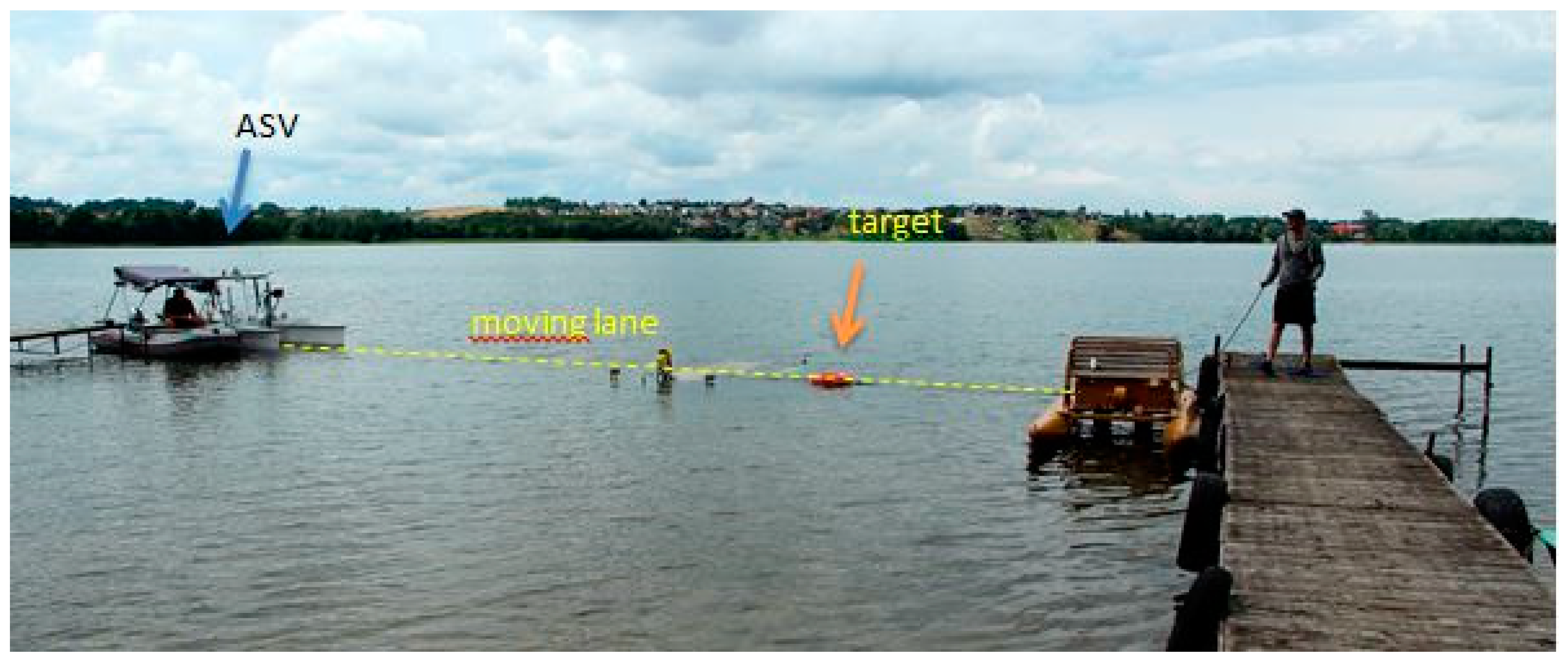
The data was collected in two scenarios, as stationary research and on a moving platform. In both scenarios, the radar was mounted on the HydroDron ASV, which is described in more detail in the next section. The research was conducted on Klodno Lake in northern Poland. In the first part, the HydroDron was moored at the end of the wooden jetty and the targets were moved to provide observational data for various targets and to characterize their detection parameters (see Figure 4).
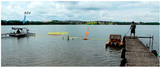
Figure 4.
Configuration for stationary research. Targets were moved along the “moving lane” in front of the stationary HydroDron.
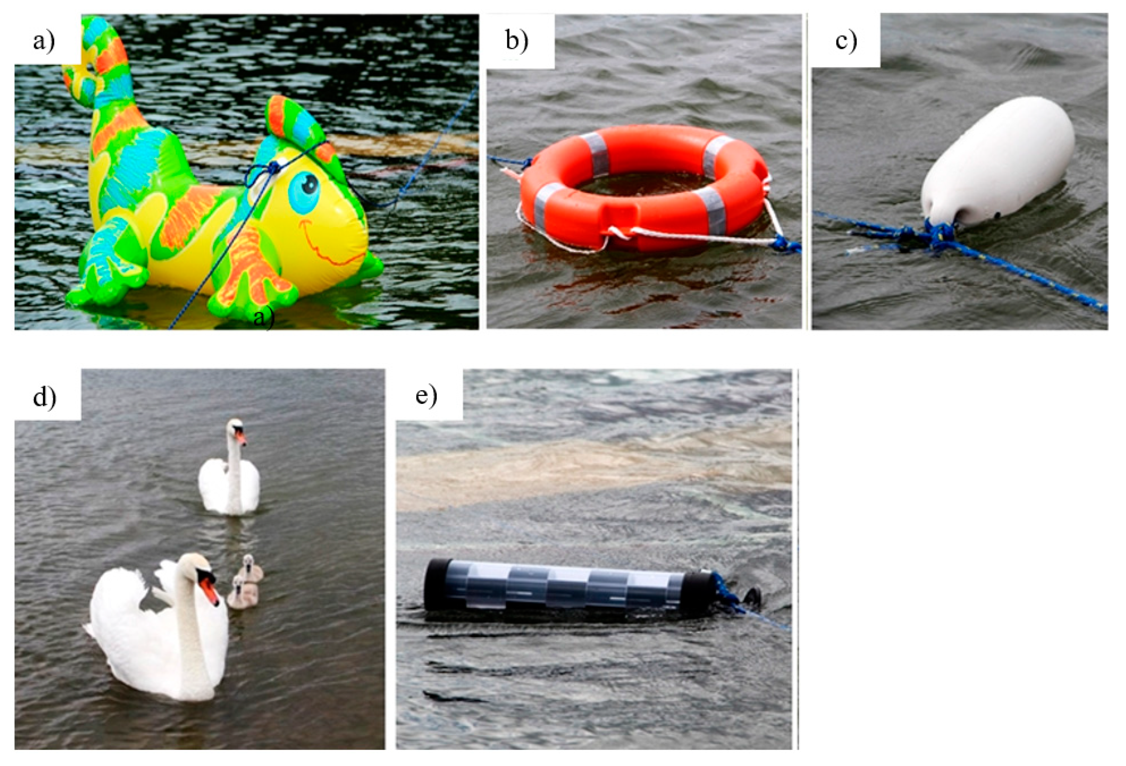
The targets used in the first scenario are presented in Figure 5, including an airtoy (dragon), lifebuoy, small boat fender, swans, and a radar reflector. These targets were selected as typical objects that could act as obstacles on the water surface. The initial research undertaken for the moving ASV has shown that the detection ranges were small for most of these targets. Therefore, better characterizing their detection in the stationary scenario was deemed important. Additionally, detection of the floating radar reflector was tested to determine if the shape of the target had an influence on detection. It has to be pointed out that even such small objects can damage or impair valuable devices carried on board the ASV or the vehicle itself.

Figure 5.
Objects used in the first scenario as targets, (a) airtoy, (b) lifebuoy, (c) fender, (d) swans, (e) radar reflector.
The second scenario was performed with a moving ASV and one target, a moving inflatable boat (Figure 6), as an example of a typical collision target on inland waters.
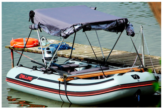
Figure 6.
Inflatable boat used in the second scenario as the target.
The goal of the second scenario was to analyze and characterize the detection while the target was moving in a typical way. The scenario was divided into three stages, corresponding to IMO Collision Regulations—head-on, crossing, and overtaking. During crossing and overtaking, different ranges were tested to obtain complex information regarding the angle of view. In general, more than 40,000 single radar measurements were collected and analyzed, representing 5 head-on, 11 crossing, and 10 overtaking situations.
4.2. Research Equipment and Configuration
In this study, the autonomous anti-collision system for the HydroDron was an automotive radar sensor, a type 42 UMRR automotive 3DHD radar with a 24 GHz microwave sensor. The radar sensor was mounted on the unmanned surface vehicle HydroDron.
The HydroDron is an autonomous catamaran, 4 m long and 2 m wide, which is being developed as a prototype intelligent autonomous multipurpose surface vehicle dedicated to hydrographic measurements. The HydroDron can perform tasks in water areas that are inaccessible or difficult to access by larger vessels. The popularity of this type of vehicle is continually increasing because of its potential to install more sensors and perform surveys in the absence of an onboard operator. The weight and maneuverability of the vehicle have been reduced to meet the objectives of its deployment. The platform has a wide range of measuring equipment—an integrated bathymetric and sonar system, an external inertial navigation system, a sound velocity profiler and sound velocity sensor, a GPS receiver, a high-frequency single-beam echosounder, a single-beam dual-frequency echosounder, two cameras, LiDAR, and a UMRR 0C Type 42 radar.
One individual sensor (3D/UHD 24 GHz radar) is employed for traffic management, simultaneously measuring many parameters, such as angle, radial velocity, range, reflection coefficient, and the entire series of motionless and motion reflector parameters. It is possible to detect many reflectors that are simultaneously in the field of view; as many as 256 targets can be detected at once. This number can be halved depending on the selected communication interface. Sorting of these reflectors is based on the range; if more than 128 targets are detected, then short-range targets are reported first. The radar is suitable for determining the speed and lighting in red light, and the sensor can be used in approaching or in receding traffic mode [19]. Figure 7 shows the radar mounted on the HydroDron platform with sensors, including the rotating and stationary camera, mounted to increase visual data collection.
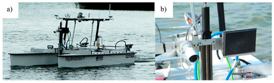
Figure 7.
Experimental system (a) ASV HydroDron and (b) radar 3D/UHD 24 GHz sensor mounted on the HydroDron platform.
4.3. Data Evaluation
Several parameters were measured in both sets of scenario experiments. The most important were the ranges and relative bearings, i.e., relative azimuth angles. In general, the range of the first detection and last detection for each target was recorded. These were direct relative measurements of the sensor in the local coordinate system, related to sensor position. Measurements from several iterations (up to 11) were collected for each scenario to obtain good statistical evaluations. The Student’s t-distribution was assumed because of the small sample size. The results showed that in this particular case it was a reasonable approach. Based on this statistical analysis, the average (Equation (1)), standard deviation (Equation (2)), and standard error (Equation (3)) were calculated for each scenario.
where:
- x represents the measured value,
- xi represents measurement in i-th iteration,
- n represents the number of iterations (number of measurements),
- is the mean value of x for n measurements,
- is the standard deviation for n measurements of x,
- is the critical value in Student’s t-distribution for n degrees of freedom and confidence, level α (68.3% in this study), and
- is the standard error of x (the standard deviation of the mean value).
Using this method, the minimum and maximum detection range can be obtained for various bearings, which provides an empirical field of view.
5. Results and Discussion
5.1. Stationary Scenario
In this scenario, measurements were performed individually for the five targets presented in Figure 5. The object travelled along the moving lane; this target was observed on the screen and the detection data were recorded. The measurement numbers varied from four to six, depending on the detection observation and results achieved; the results are compiled in Table 2. At least four in/out iterations were made for each artificial target. If the results were coherent, performing more measurements was pointless. The results achieved were very cohesive and as such, the number of observations performed was reduced. The data achieved were enough to determine if the particular object was well or poorly detected. The exemption to this rule were the swans, which are live animals and could not be steered. They approached the vehicle twice and moved away. Thus, two measurements for the minimum detection range and two for the maximum detection range were measured.
Table 2.
Minimum and maximum detection distance results from the Stationary Scenario.
Table 2 presents the minimum and maximum distances of detection along the moving lane. The mean values as well as standard deviations and standard errors are provided for the minimum detection and the maximum detection range. The fender was not detected at all and thus it is not included in the table. The swans were observed for a few minutes and during this time two measurement lines were chosen. The best detection results were achieved for the radar reflector, wherein the maximum distance was determined at the end of measurement line although the real maximum distance was larger. The measured minimum distance was the best for all the analyzed targets. Despite the complicated direct target observations on the screen and the target being mixed with others, the post-processing of data allowed the airtoy detection to be extracted and good data were obtained. The lifebuoy target visibility was very good and the target was easily distinguishable. The swans were visibly distorted but observable.
The results indicate that most objects were visible at a distance of approximately 13–17 m. The minimum distance was generally 3–4 m based on a geometrical distribution. In summary, this stage of research shows that the radar can detect even small targets for anti-collision. However, small floating targets, such as fenders and small buoys, are not detected.
5.2. Moving Platform Scenario
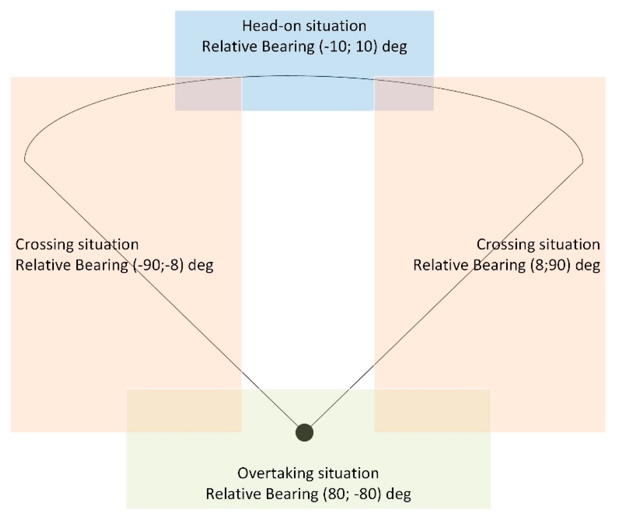
In this scenario, three cases were analyzed when head-on, crossing, and overtaking motion. During the experiment, the ASV moved with a stable course and speed, while the inflatable boat moved according to the desired trajectory. Both boats were simulating typical collision situations that could reasonably occur while the ASV was deployed to collect measurements. In each of the three parts, the target was approaching its own ship from various relative bearings. In Figure 8, the situation is explained graphically, presenting the ranges of the relative bearing for each situation. It should be pointed out, that the terms head-on, corssing, and overtaking was slightly modified compared to the traditional understanding of IMO COLREG (Collision Regulations) requirements. For the purpose of this research, we proposed that head-on means the situation in which the target is approaching from the relative bearings in the range (−10°;10°); crossing means the situation in which the target is approaching from the relative bearings in the ranges (−90°; −8°) and (8°; 90°); and overtaking means the situation in which the target is approaching from the relative bearings in the ranges (80°; −80°). As it can be seen in Figure 8, the areas slightly overlap each other and the relative course of the object decides the type of movement. Such definition of the areas in the scenario ensures the analysis of the maximum detection range in the entire filed of view of the radar antenna.
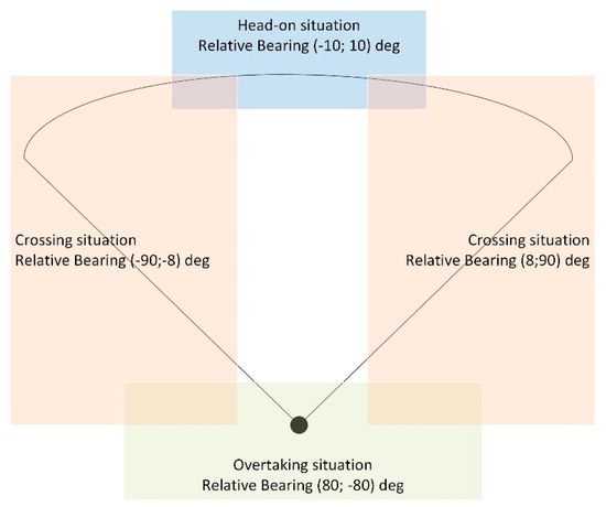
Figure 8.
Situation areas in dynamic scenario.
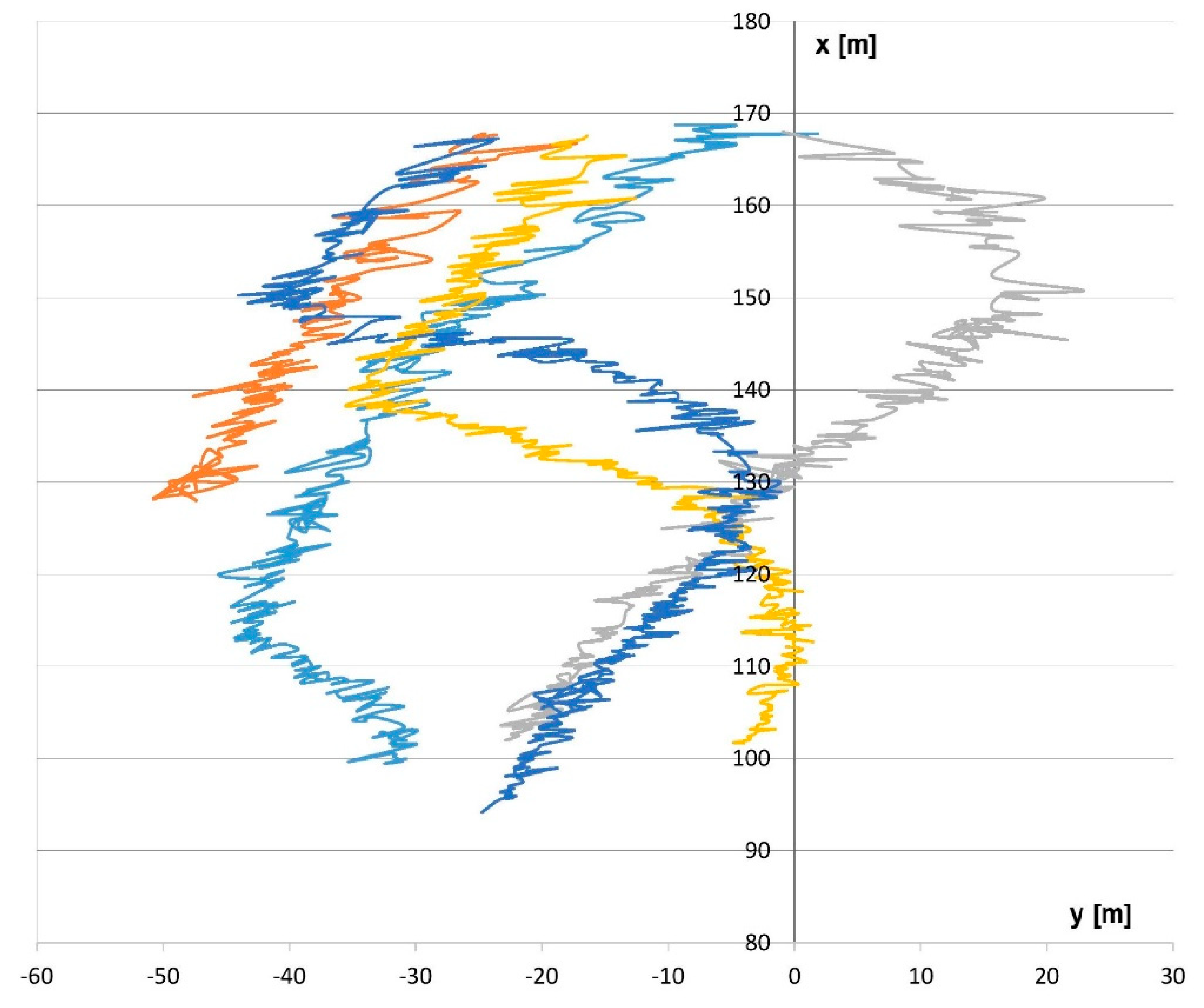
For head-on motion, the boats were moving toward each other from a large distance. The goal was to determine the maximum detection distance for such a boat. According to the declarative field of view, the head-on course should provide the maximum detection distance. The tracks analyzed in this scenario (after entering the field of view) are presented in Figure 9. The own ship was located in the beginning of the coordinate system and the x-axis is oriented with a relative bearing of 0°. The relative tracks of the targets after entering the field of view are given.

Figure 9.
Moving Platform Scenario tracks for head-on motion experiments.
The results for the head-on situation are compiled in Table 3. Because of the good convergence of measurements, it was decided that five iterations were good enough in this situation.
Table 3.
Moving Platform Scenario results for head-on motion.
As shown in Table 3, the mean detection range for this type of boat is 169.04 m. This measurement was reproducible, such that according to the 3-sigma rule, the real detection range should vary from 168.5 to 169.5 m. This result generally confirms the declarative detection range for small cars onshore. The relative bearings confirmed the scenario assumptions (head-on situation) and the relative speed shows that the target approached at a nearly constant speed of 2.5 m/s.
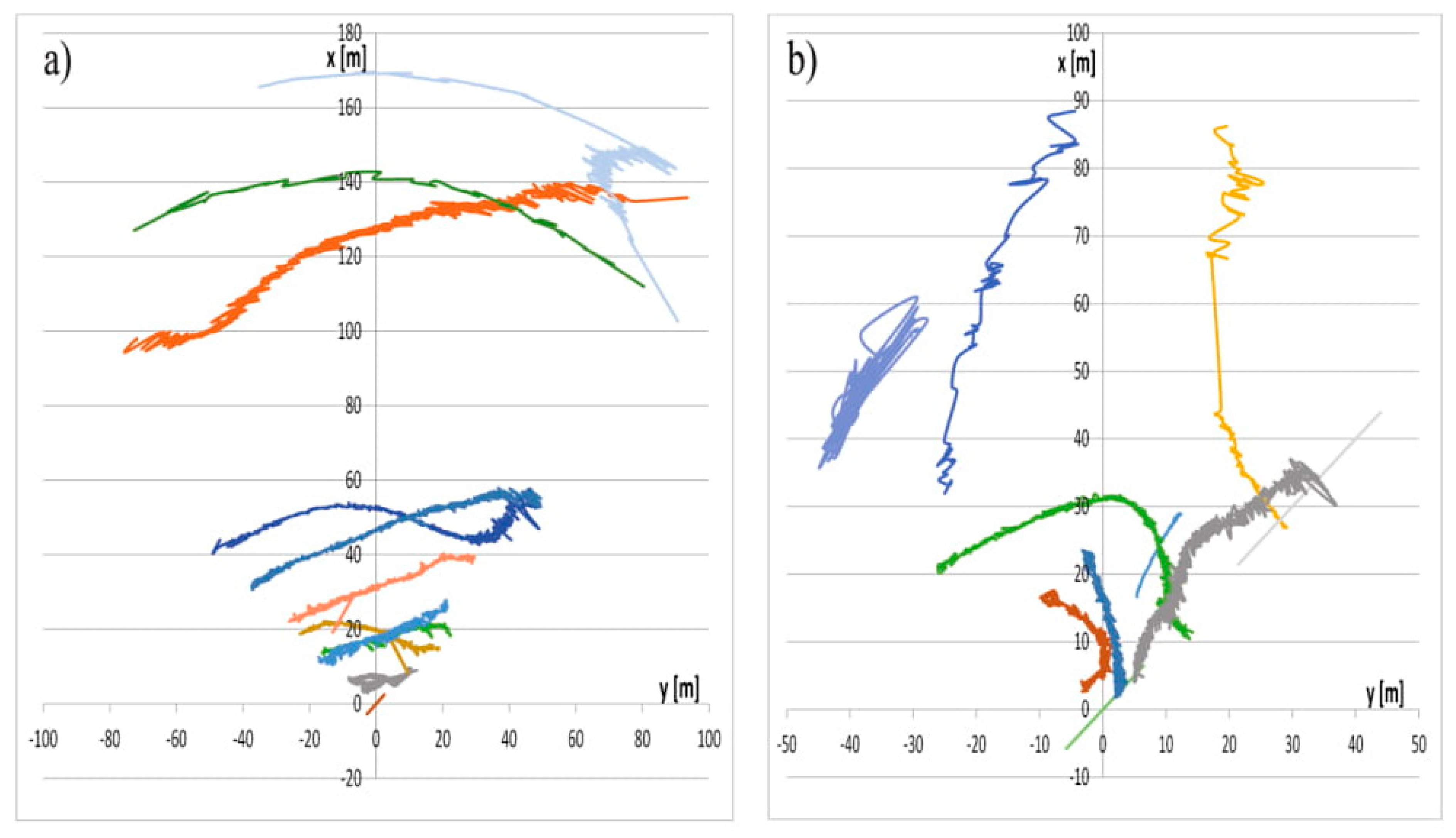
In the crossing and overtaking motion, the main goal was to find the angles at which the target appeared in the field of view and then left it. Eleven tracks were recorded for both the crossing and overtaking motion experiments. The relative tracks are presented in Figure 8. The graphs show a plan view, in which the HydroDron is in the middle of the body frame coordinate system and the x-axis points toward the heading. The observed platform presented in Figure 6 (an inflatable boat) was moving according to the established patterns. The HydroDron was moving with a steady course and speed, while the target was maneuvering. As it can be seen in Figure 10a, the tracks were recorded in various distances, from a few meters up to 170 m (detection maximum for this type of target). In the case of overtaking movement (Figure 10b), only the moment of the first target detection is important and thus only the incoming target was taken into account. Notably, the tracks were selected to verify the angles over various distances, both smaller and bigger. The measurement results for crossing the tracks are provided in Table 4.

Figure 10.
Moving Platform Scenario tracks for (a) crossing and (b) overtaking motion experiments.
Table 4.
Moving Platform Scenario results for the crossing motion experiments.
As shown in Table 4, the statistics for the crossing motion experiments are divided into the port side and the starboard side of the ASV (and radar). Additionally, the results are presented separately for the target coming into the field of view and then leaving it. The sample size was small due to the complexity of the study, so the T-distribution was used. In each case presented in Table 3, the mean value is within (40°–45°), which can be treated as the typical angular restriction of the field of view. However, the maximum values are more than 50° and the distribution is more or less symmetrical. Furthermore, the standard deviation and standard error achieved in these experiments are relatively big because the crossing motion occurred at various ranges. Based on evaluation of the detailed data, we found that at larger ranges, the angular field of view was smaller and the crossing target entered the view later; for example, when the target appeared at 169.2 m, the angle was −12°.
The observations made in the crossing motion experiments were confirmed in the measurements for the overtaking situation, as shown in Table 5. Seven measurements are presented, together with statistics based on the T-distribution assumption. In these experiments, only incoming targets were analyzed, and the absolute value of the bearing was calculated without dividing it into portside and starboard side.
Table 5.
Moving Platform Scenario results for the overtaking motion experiments.
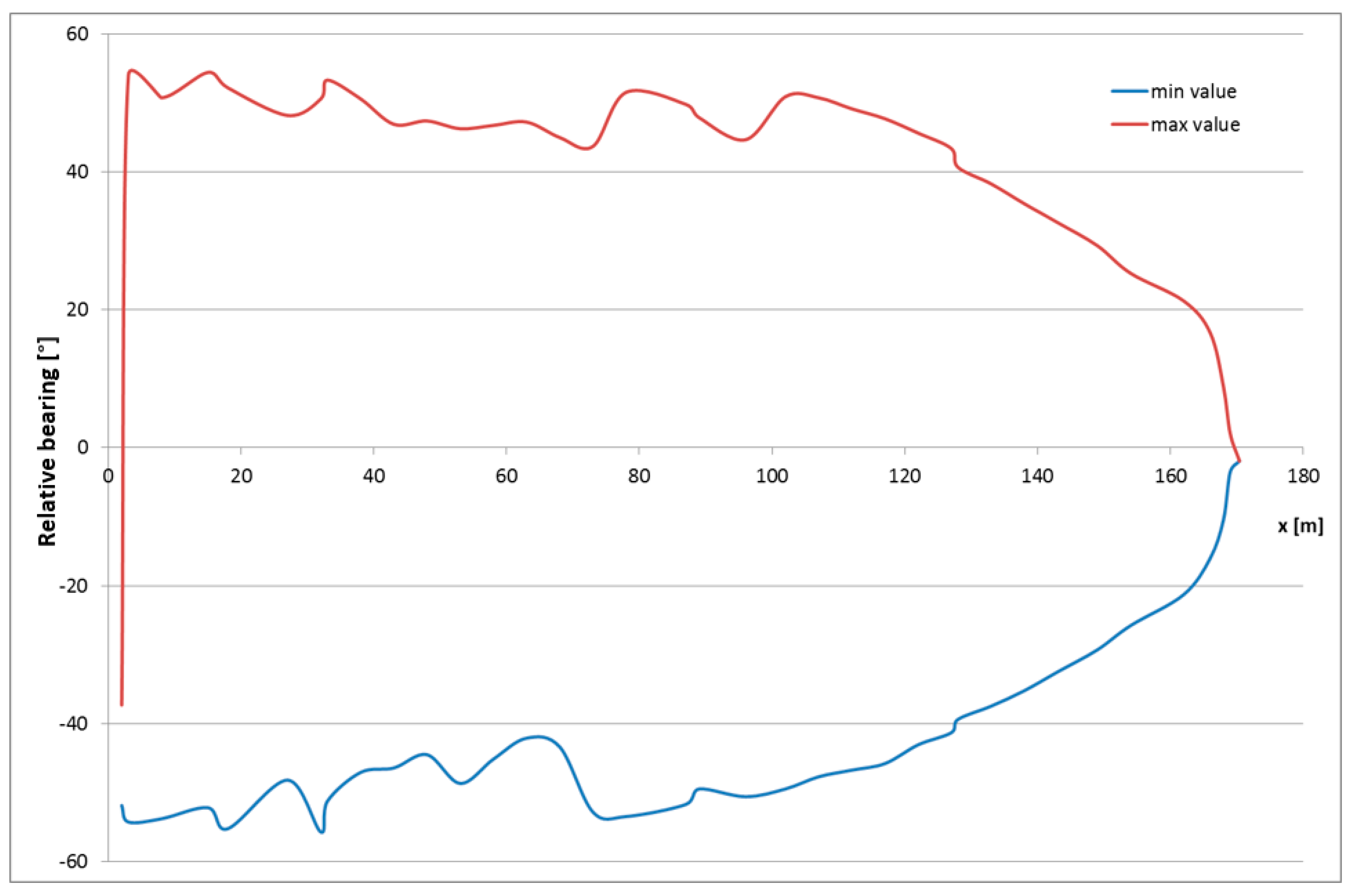
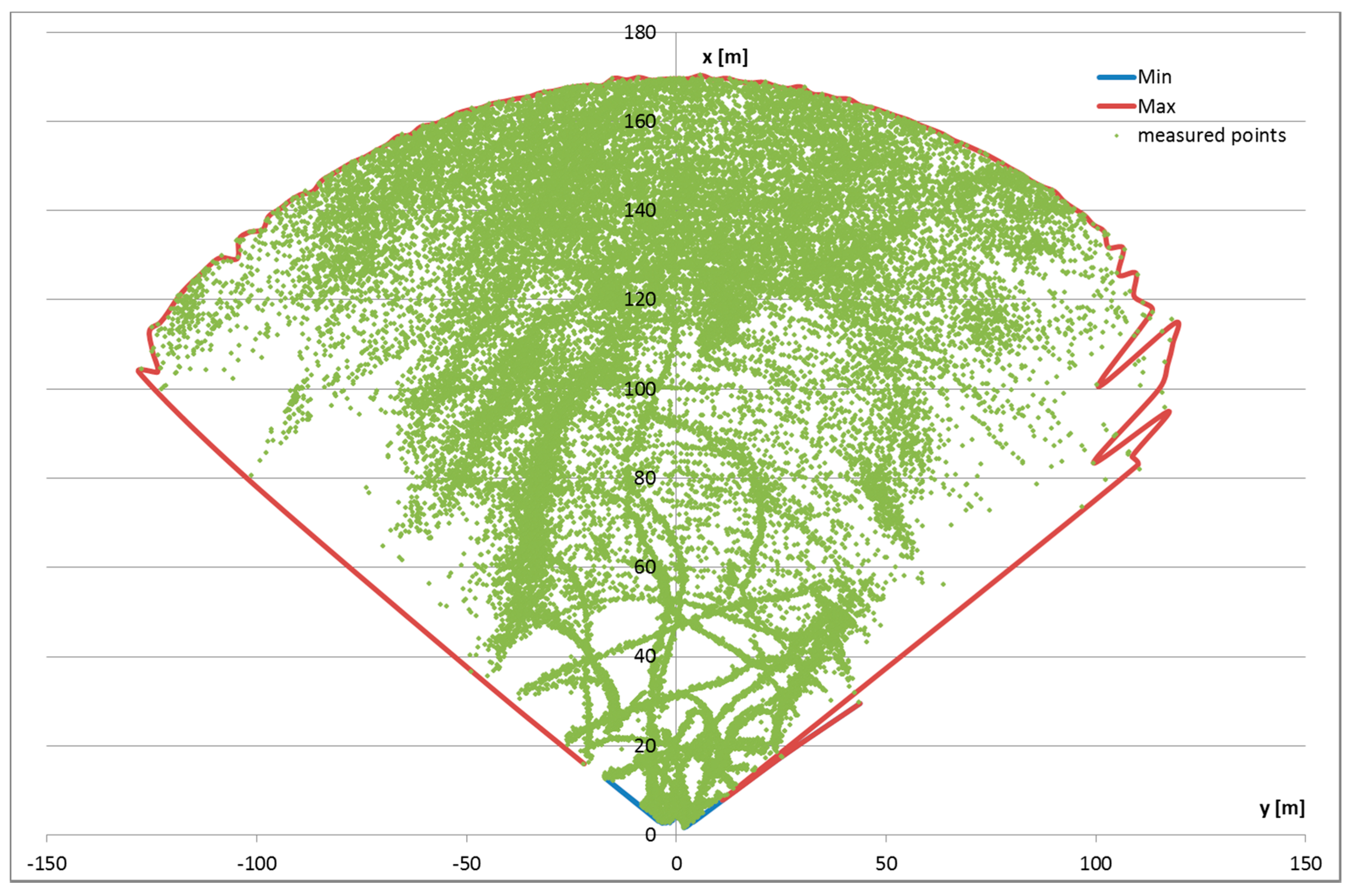
Overtaking usually occurs at relatively small distances, a situation that was reproduced in this research. This results in a better and more accurate mean value of nearly 50°. In the first measurement, where the distance was more than 60 m, the bearing was smaller. Summarizing these observations, the angular field of view should be determined as a function of range; for small ranges it is nearly linear (approximately 45–50°), but for bigger ranges the field of view falls exponentially. To verify this hypothesis, the relative bearing graphs are presented in Figure 11 and Figure 12. Figure 11 presents the relationship between the range and relative bearings, wherein the minimum- and maximum-recorded bearings for each distance are plotted. The envelope for more than 40,000 measurements collected in the Moving Platform Scenario is presented.
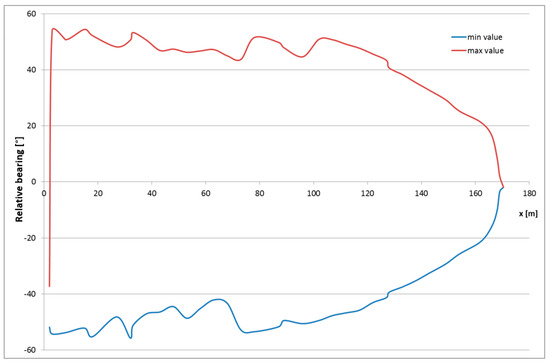
Figure 11.
Relative bearing as a function of x-coordinate in the Moving Platform Scenario.
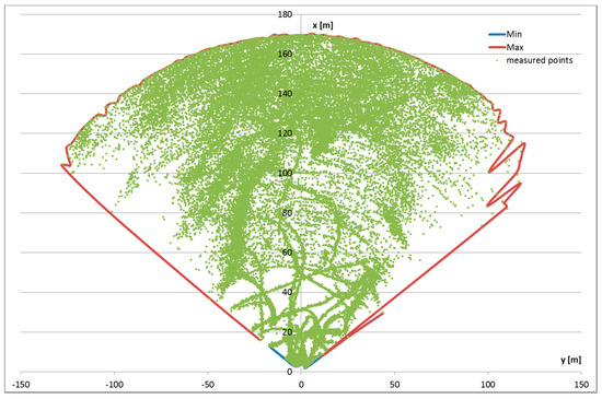
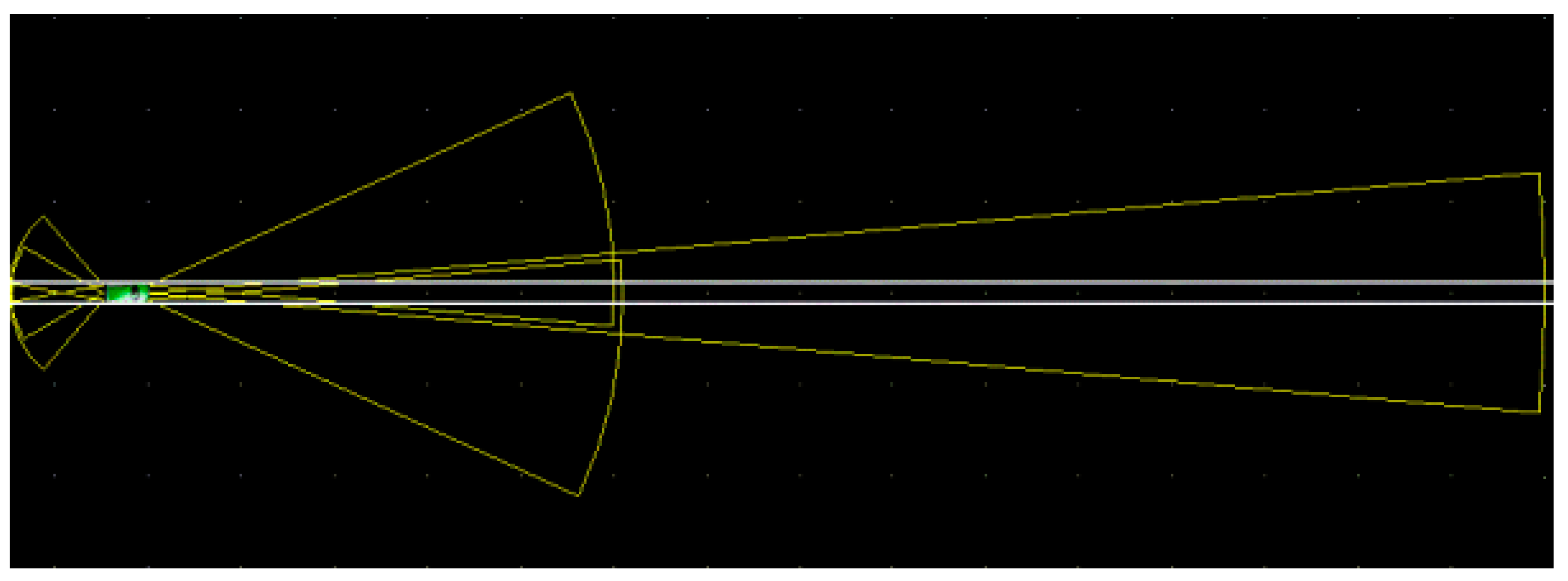
Figure 12.
Empirical detection pattern based on measurements collected in the Moving Platform; measured points are in green and the envelope is shown with a red line.
As shown in Figure 11, larger x-coordinates correspond to smaller bearings to detect the target. Although the maximum detection range is still approximately 170 m, the geometry of the sensor and experimental configuration suggests that targets at smaller distances will not be detected. For example, a target at a distance of 150 m at a relative bearing of 40° will not be detected by radar. This consideration leads directly to the detection area pattern presented in Figure 12. The graph shows the measurement points positions in the Cartesian coordinate body system. The vertical axis indicates the direction of ASV movement with an envelope of detectable targets. The field of view appears as a quarter circle with a radius of almost 170 m. Up to approximately 120 m, the angular width of the field of view is almost identical (90–100°); at further distances, the effective width is smaller. Notably, no lobes are observed, which could be expected, based on the declarative beam pattern. The envelope presented in the graph is generally a smooth line that was created based on the minimum and maximum range values for each bearing with a resolution of 1°. A comparison with the measurement points indicates that this envelope is rather optimistic and the effective field of view is narrower. Some disturbances to the envelope can be observed at distances of about 100 m (x-axis), which are larger on the starboard side, where the graphed line is less smooth. One reason for this might be the mounting on the boat left of the echosounder pole. This hypothesis should be verified in the future.
6. Conclusions
The research in this study provides an empirical analysis of surface target detection in a water environment with automotive radar, which can be used for the future development of tracking and anti-collision systems for ASVs. The research focused on identifying the detection ranges and field of view for various targets. Typical objects that could be met in the water environment were analyzed, including a boat and floating objects.
The overarching goal of the research was to verify a novel approach for object detection in a water environment. The novelty was based on using radar sensor for this approach, which is usually implemented in cars for road situations. This approach may in the future overcome the disadvantages of other systems used for anti-collision in ASV, namely laser rangefinders, lidars, and cameras. The proposed system was verified in real conditions with the online recordings.
The research showed that the system was capable of detecting many small targets but some objects, such as a fender, were not detected. Therefore, detection depends both on the size of the target and the material. In general, objects that are air inflated, such as fenders or airtoys, show worse detectability than solid targets, such as lifebuoys. Detection can be significantly improved using a radar reflector, however these reflectors are not usually deployed in practice. In general it can be said that the maximum detection range of small targets is about 15 m, while in very short distance (less than 3 m in research configuration) they are in the shadow due to antenna mounting. It can be assumed that 15 m is a reasonable distance to perform hard anti-collision maneuvers (like full stop) for such a small target with good maneuverability, however this judgment has to be verified in future research.
The second part of the study was conducted using an inflatable boat as the model object in motion. A complex analysis of the field of view for this target was performed, including the radial distances at different angles for various movement parameters. In general, the empirical research confirmed the product limitations and performance declared by the producers, under the assumption that an inflatable boat could be treated as a small car based on their size similarities. The maximum detecting range, confirmed with statistical post-processing, was about 170 m, while the field of view was about 100° (50° for each side). These values seem to be reasonable for planning anti-collision maneuvers with moving targets.
In summary, for larger targets that represent the greatest risk, the radar system provides good detection for anti-collision purposes. For smaller targets, the detection ranges are smaller, although for most targets, it would be small enough for the ASV to maneuver around. Additionally, some small targets were not detected. Generally, the automotive radar system may be a good basis for an ASV anti-collision system; however it should be supplemented with the integration of additional sensors, such as laser rangefinders. In the future, the detection stability and additional small targets should be investigated. It would be also interesting to see how this kind of radar would react in a sea environment. ASVs used at sea might be also a possible target of implementation.
Author Contributions
Conceptualization, A.S. and W.K.; methodology, W.K.; bibliography review, A.S.; acquisition, analysis, and interpretation of data, W.K., D.G-S. and W.M.; writing—original draft preparation, W.K.; writing—review and editing, A.S.
Funding
This study was funded by the European Regional Development Fund under the 2014-2020 Operational Programme Smart Growth; as part of the project, “Developing of autonomous/remote operated surface platform dedicated hydrographic measurements on restricted reservoirs” implemented as part of the National Centre for Research and Development competition, INNOSBZ and under grant No 1/S/IG/16 financed from a subsidy of the Ministry of Science and Higher Education for statutory activities.
Conflicts of Interest
The author(s) declare(s) that they have no conflict of interest regarding the publication of this paper.
References
- Droeschel, D.; Schwarz, M.; Behnke, S. Continuous mapping and localization for autonomous navigation in rough terrain using a 3D laser scanner. Robot. Auton. Syst. 2017, 88, 104–115. [Google Scholar] [CrossRef]
- Williams, G.M. Optimalization of eyesafe avalanche photodiode lidar for automobile safety and autonomous navigation systems. Opt. Eng. 2017, 56, 031224. [Google Scholar] [CrossRef]
- Huang, L.; Chen, S.; Zhang, J.; Cheng, B.; Liu, M. Real-Time Motion Tracking for Indoor Moving Sphere Objects with a LiDAR Sensor. Sensors 2017, 17, 1932. [Google Scholar] [CrossRef] [PubMed]
- Song, R.; Liu, Y.; Bucknall, R. Smoothed A* algorithm for practical unmanned surface vehicle path planning. Appl. Ocean Res. 2019, 83, 9–20. [Google Scholar] [CrossRef]
- Korayem, M.H.; Esfeden, R.A.; Nekoo, S.R. Path planning algorithm in wheeled mobile manipulators based on motion of Arms. J. Mech. Sci. Technol. 2015, 29, 1753–1763. [Google Scholar] [CrossRef]
- Maclachlan, R.; Mertz, C. Tracking of Moving Objects from a Moving Vehicle Using a Scanning Laser Rangefinder. In Proceedings of the 2006 IEEE Intelligent Transportation Systems Conference Proceedeings, Toronto, ON, Canada, 17–20 September 2006; pp. 301–306. [Google Scholar] [CrossRef]
- Wei, P.; Cagle, L.; Reza, T.; Ball, J.; Gafford, J. LiDAR and camera detection fusion in a real-time industrial multi-sensor collision avoidance system. Electronics 2018, 7, 6. [Google Scholar] [CrossRef]
- Polvara, R.; Sharma, S.; Wan, J.; Manning, A.; Sutton, R. Obstacle avoidance approaches for autonomous navigation of unmanned surface vehicles. J. Navig. 2017, 71. [Google Scholar] [CrossRef]
- Almeida, C.; Franco, T.; Ferreira, H.; Martins, A.; Santos, R.; Almeida, J.M.; Silva, E. Radar based collision detection developments on USV ROAZ II. In Proceedings of the Oceans 2009-Europe, Bremen, Germany, 11–14 May 2009; pp. 1–6. [Google Scholar]
- Zhuang, J.Y.; Zhang, L.; Zhao, S.Q.; Cao, J.; Wang, B.; Sun, H.B. Radar-based collision avoidance for unmanned surface vehicles. China Ocean Eng. 2016, 30, 867–883. [Google Scholar] [CrossRef]
- Eriksen, B.-O.H.; Wilthil, E.F.; Flåten, A.L.; Brekke, E.F.; Breivik, M. Radar-based Maritime Collision Avoidance using Dynamic Window. In Proceedings of the IEEE Aerospace Conference, Big Sky, MT, USA, 3–10 March 2018. [Google Scholar] [CrossRef]
- Gresham, I.; Jain, N.; Budka, T. A 76–77GHz Pulsed-Doppler Radar Module for Autonomous Cruise Control Applications. In Proceedings of the IEEE MTT-S International Microwave Symposium (IMS2000), Boston, MA, USA, 11–16 June 2000; pp. 1551–1554. [Google Scholar]
- Wolff, C. Frequency-Modulated Continuous-Wave Radar. Radar Tutorial. Available online: http://www.radartutorial.eu/02.basics/pubs/FMCW-Radar.en.pdf (accessed on 31 July 2018).
- Ramasubramanian, K. Using a Complex-Baseband Architecture in FMCW Radar Systems; Texas Instrument: Dallas, TX, USA, 2017; Available online: http://www.ti.com/lit/wp/spyy007/spyy007.pdf (accessed on 3 August 2018).
- Brückner, S. Maximum Length Sequences for Radar and Synchronization. Cuvillier. Available online: https://cuvillier.de/uploads/preview/public_file/9760/9783736991927_Leseprobe.pdf (accessed on 2 August 2018).
- Automotive Radar—A Tale of Two Frequencies. life.augmented. Available online: https://blog.st.com/automotive-radar-tale-two-frequencies/ (accessed on 3 August 2018).
- Sjöqvist, L.I. What Is an Automotive Radar? Gapwaves. Available online: http://blog.gapwaves.com/what-is-an-automotive-radar (accessed on 3 August 2018).
- Schneider, M. Automotive Radar—Status and Trends. In Proceedings of the GeMiC 2005, Ulm, Germany, 5–7 April 2005; pp. 144–147. [Google Scholar]
- Ramasubramanian, K.; Ramaiah, K.; Aginsky, A. Moving from Legacy 24 GHz to State-Of-The-Art 77 GHz Radar; Texas Instrument: Dallas, TX, USA, 2017; Available online: http://www.ti.com/lit/wp/spry312/spry312.pdf (accessed on 3 August 2018).
- Matthews, A. What Is Driving the Automotive LiDAR and RADAR Market? Automotive Electronic Specifier, Kent, UK. 2017. Available online: https://automotive.electronicspecifier.com/sensors/what-is-driving-the-automotive-lidar-and-radar-market#downloads (accessed on 3 August 2018).
- Bronzi, D.; Zou, Y.; Villa, F. Automotive Three-Dimensional Vision Through a Single-Photon Counting SPAD Camera. IEEE Trans. Intell. Transp. Syst. 2016, 17, 782–795. [Google Scholar] [CrossRef]
- Mende, R.; Rohling, H. New Automotive Applications for Smart Radar Systems; Smartmicro Publications: Braunshweig, Germany; Available online: http://www.smartmicro.de/company/publications/ (accessed on 3 August 2018).
- Smartmicro. Available online: http://www.smartmicro.de/fileadmin/user_upload/Documents/TrafficRadar/UMRR_Traffic_Sensor_Type_42_Data_Sheet.pdf (accessed on 22 August 2018).
- Jo, J.; Tsunoda, Y.; Stantic, B. A Likelihood-Based Data Fusion Model for the Integration of Multiple Sensor Data: A Case Study with Vision and Lidar Sensors. In Robot Intelligence Technology and Applications 4; Springer International Publishing: Basel, Switzerland, 2017; Volume 447, pp. 489–500. [Google Scholar]
- Jooho, L.; W, W.J.; Nakwan, K. Obstacle Avoidance and Target Search of an Autonomous Surface Vehicle for 2016 Maritime RobotX Challenge. In Proceedings of the IEEE OES International Symposium on Underwater Technology (UT), Busan, Korea, 21–24 February 2017. [Google Scholar]
- Mei, J.H.; Arshad, M.R. COLREGs Based Navigation of Riverine Autonomous Surface Vehicle. In Proceedings of the IEEE 6TH International Conference on Underwater System Technology, Penang, Malaysia, 13–14 December 2016; pp. 145–149. [Google Scholar]
- Barton, A.; Volna, E. Control of Autonomous Robot using Neural Networks. In Proceedings of the International Conference on Numerical Analysis and Applied Mathematics 2016 (ICNAAM-2016), Rhodes, Greece, 19–25 September 2016; Volume 1863. [Google Scholar]
- Ko, B.; Choi, H.J.; Hong, C. Neural Network-based Autonomous Navigation for a Homecare Mobile Robot. In Proceedings of the 2017 IEEE International Conference on Big Data and Smart Computing (BIGCOMP), Jeju, Korea, 13–16 February 2017; pp. 403–406. [Google Scholar]
- Praczyk, T. Neural anti-collision system for Autonomous Surface Vehicle. Neurocomputing 2015, 149, 559–572. [Google Scholar] [CrossRef]
- Lil, J.; Bao, H.; Han, X. Real-time self-driving car navigation and obstacle avoidance using mobile 3D laser scanner and GNSS. Multimed. Tools Appl. 2016, 76, 23017–23039. [Google Scholar]
- Guan, R.P.; Ristic, B.; Wang, L.P. Feature-based robot navigation using a Doppler-azimuth radar. Int. J. Control 2017, 90, 888–900. [Google Scholar] [CrossRef]
- Guerrero, J.A.; Jaud, M.; Lenain, R. Towards LIDAR-RADAR based Terrain Mapping. In Proceedings of the 2015 IEEE International Workshop on Advanced Robotics and its Social Impacts (ARSO), Lyon, France, 30 June–2 July 2015. [Google Scholar]
- Hollinger, J.; Kutscher, B.; Close, B. Fusion of Lidar and Radar for detection of partially obscured objects. In Proceedings of the Unmanned Systems Technology XVII, Baltimore, MD, USA, 22 May 2015; Volume 9468. [Google Scholar]
- Mikhail, M.; Carmack, N. Navigation Software System Development for a Mobile Robot to Avoid Obstacles in a Dynamic Environment using Laser Sensor. In Proceedings of the SOUTHEASTCON 2017, Charlotte, NC, USA, 31 March–2 April 2017. [Google Scholar]
- Jeon, H.C.; Park, Y.B.; Park, C.G. Robust Performance of Terrain Referenced Navigation Using Flash Lidar. In Proceedings of the 2016 IEEE/Ion Position, Location and Navigation Symposium (PLANS), Savannah, GA, USA, 11–16 April 2016; pp. 970–975. [Google Scholar]
- Jiang, Z.; Wang, J.; Song, Q. Off-road obstacle sensing using synthetic aperture radar interferometry. J. Appl. Remote Sens. 2017, 11, 016010. [Google Scholar] [CrossRef]
- Oh, H.N.H.; Tsourdos, A.; Savvaris, A. Development of Collision Avoidance Algorithms for the C-Enduro USV. IFAC Proc. Vol. 2014, 47, 12174–12181. [Google Scholar] [CrossRef]
- Stateczny, A.; Kazimierski, W. Selection of GRNN network parameters for the needs of state vector estimation of manoeuvring target in ARPA devices. In Photonics Applications in Astronomy, Communications, Industry, and High-Energy Physics Experiments IV, Proceedings of the Society of Photo-Optical Instrumentation Engineers (SPIE), Wilga, Poland, 30 May–2 June 2005; Romaniuk, R.S., Ed.; SPIE: Bellingham, WA, USA, 2006; Volume 6159, p. F1591. [Google Scholar]
- Kazimierski, W.; Zaniewicz, G.; Stateczny, A. Verification of multiple model neural tracking filter with ship’s radar. In Proceedings of the 13th International Radar Symposium (IRS), Warsaw, Poland, 23–25 May 2012; pp. 549–553. [Google Scholar]
- Xinchi, T.; Huajun, Z.; Wenwen, C.; Peimin, Z.; Zhiwen, L.; Kai, C. A Research on Intelligent Obstacle Avoidance for Unmanned Surface Vehicles. Proc. Chin. Autom. Congr. (CAC) 2018. [Google Scholar] [CrossRef]


© 2019 by the authors. Licensee MDPI, Basel, Switzerland. This article is an open access article distributed under the terms and conditions of the Creative Commons Attribution (CC BY) license (http://creativecommons.org/licenses/by/4.0/).