Article

An Approach to Improve the Positioning Performance of GPS/INS/UWB Integrated System with Two-Step Filter

1
School of Environment Science and Spatial Informatics, China University of Mining and Technology, Xuzhou 221116, China
2
School of Information and Control Engineering, China University of Mining and Technology, Xuzhou 221116, China
*
Author to whom correspondence should be addressed.
Remote Sens. 2018, 10(1), 19; https://doi.org/10.3390/rs10010019
Submission received: 10 October 2017 / Revised: 18 December 2017 / Accepted: 20 December 2017 / Published: 23 December 2017

Abstract

:
The integration of Inertial Navigation System (INS) and Global Positioning System (GPS) single-point-positioning (SPP) mode cannot meet the requirements of high-accuracy navigation. Range observation through ultra-wideband (UWB) is an effective means to enhance the reliability and accuracy of GPS/INS integrated navigation, particularly in environments where GPS availability is poor. Because it is difficult for UWB signal to achieve large-scale intervention coverage, an enhanced GPS/INS/UWB integrated scheme with positioning error correction is proposed to improve the position accuracy in the UWB signal outage scenario. The position difference between the GPS/INS integrated solution and the GPS/INS/UWB integrated solution is predicated as the error correction for GPS/INS/UWB integrated navigation in a UWB signal challenging environment. Position correction information in the north and east directions is input to the two-step filter to decrease the error of GPS/INS integrated navigation in single-point-positioning. In order to validate the proposed method, a real experiment is conducted. The results indicate that the enhanced GPS/INS/UWB integrated scheme with positioning error correction is able to improve the position accuracy of GPS/INS/UWB integrated navigation when UWB signal is unavailable.

Graphical Abstract

1. Introduction

When used in combination, global navigation satellite system (GNSS) and inertial navigation systems (INS) can be used to collect geographic data of specific objects, such as attitude, velocity, and position. These systems have uses in everything from farmland to navigation to military operations. GNSS provides reliable positional information that can be updated in real time, and INS indicates attitude over short periods. Also, a GNSS receiver processes position results from satellite signals, and INS is a self-contained device for measuring velocity and attitude. Clearly, the integration of both GNSS and INS would greatly enhance performance over each individual system [1]. On the other hand, in environments where GPS signal reception is limited or non-existent, the performance of GPS/INS integrated is severely impeded. High-accuracy precise point positioning-real time kinematic (PPP-RTK) and multi-GNSS [2] are the important methods for navigation and positioning in obstructed environments [3]. PPP-RTK was developed to overcome the limitation in ambiguity solution and give centimeter-accuracy in a few seconds [4]. PPP-RTK is a relative technique and the ‘single-receiver user’ integer ambiguities are actually double-differenced ambiguities [5]. It is possible to integrate PPP and NRTK (Network Real-Time Kinematic) into a seamless positioning service, which provides an accuracy of about 10 cm anywhere. It can also be upgraded to a few centimeters within a regional network [6]. Integer ambiguity solution at a single station can be performed by introducing predetermined uncalibrated phase delays (UPDs) into the float ambiguity estimates of precise point positioning (PPP) [7]. The multi-GNSS positioning method is able to increase the navigation parameters [8], but it offers little advantage on improving the space distribution of GPS satellites. In order to ensure the real-time performance of navigation and reduce cost, the SPP method is used in the GPS/INS/UWB integrated scheme and only GPS signal is used in data resolution here.
Recently, the ultra-wide bandwidth (UWB) ranging method, with its extensive range of time transfer, has attracted great interest for its applications in positioning and tracking distance measurements [9]. UWB signals are relatively robust and resistant to frequency-selective fading and the ability for both high-capacity communication and strong solution over time. A great deal of research has addressed means by which UWB might be integrated with GPS to improve the accuracy of positioning in environments in which GPS does not work well alone. For instance, an augmented carrier-phase real-time kinematic (RTK) float filter can be augmented with UWB range measurements, which resolves challenges related to the ratio and time of ambiguity resolution [9]. Systems that tightly incorporate GPS-based observations and UWB-based assessments of range were able to account for systematic UWB errors in real time, but an extended Kalman filter (EKF) showed further error states [10]. Integrating GPS and UWB can allow highly accurate positioning by testing a number of external corner points on an eight-storey building [11]. A GPS/UWB integrated system was used to maintain any submeter-level position solutions. A commercially available UWB ranging system was used as part of the tightly coupled GPS-UWB RTK system [12]. This integrated system was more accurate and offered better fixed-ambiguity solutions than GPS alone. Even in environments in which GPS does not work well, accuracy was still tangible at the sub-decimeter level [13]. A vehicle-relative solution was reached within a vehicle-to-infrastructure (V2I) using an extended Kalman filter with a differential GPS pseudorange. Carrier-phase measurements were used in conjunction with UWB ranges of the distance between the vehicle in question and two points on either side of the road [14]. Collaborative positioning was reached by substituting GPS and UWB data between the vehicles. This system was found to perform better than GPS alone [15]. A cooperative vehicle-to-vehicle (V2V) method of relative positioning was developed using a federated filtering scheme within a vehicular ad hoc network (VANET) that had been built using techniques involving UWB ranging and differential GPS (DGPS). Doppler, UWB-range observations, and GPS pseudorange at an accuracy of 20–30 cm were used to estimate V2V baseline [16]. A tightly coupled fusion of impulse radio UWB (IR-UWB) and DGPS for peer-to-peer ranging was used to determine the positions of aircraft flying in close formation [17]. A cooperative positioning solution with GNSS and UWB was developed to precisely locate vehicles traveling through areas in which GNSS does not work well or is blocked. UWB range observations allowed the system to reach levels of accuracy at the decimeter scale or finer, even in scenarios full of motion [18]. The detailed process of UWB performance testing in the context of navigating and positioning was analyzed in GNSS-compromised environments, which illustrates the potential of UWB for long-time tracking and navigation, without the expansion of drift errors. This makes mapping possible and reliable for commercial applications [19].
To further enhance the reliability and availability of GPS/INS integration, the positioning techniques based on UWB range measurements and the corresponding algorithms were proposed and could improve performance. For areas in which the UWB positioning infrastructure is available, one system augments GPS and the microelectromechanical system (MEMS)–INS by performing low-cost UWB measurements. Multi-sensor fusion algorithms could determine the positions of moving objects to an accuracy of 20 cm in environments in which UWB range measurements are possible [20]. A low-cost GPS/INS navigation incorporating impulse radio signals through ultra-wideband transceivers in environments in which GPS does not work well or at all can facilitate a horizontal accuracy at a level of 0.5 m with robust performance [21]. A tightly coupled INS/UWB system for pedestrian indoor applications was developed. This robust integration, combined with the integrity method, has been implemented in a tightly coupled system [22]. A new, enhanced, tightly coupled cooperative positioning technique was developed by adding ultra-wide bandwidth (UWB)-based inter-vehicular range measurements. This method outperformed the INS-aided tight cooperative positioning method, the tight cooperative positioning method, and the DGPS by 60%, 65%, and 73%, respectively, in the GPS outage scenario [23].
These researches showed that the additional UWB measurements can significantly improve horizontal positioning accuracy, particularly in environments where GPS availability is poor. Most studies have focused on improving navigation information in environments with reliable UWB signal reception. As such, the effect of UWB during signal blockage has not been taken into account. To tap the potential of UWB observation, an enhanced GPS/INS/UWB integrated scheme with position error correction is proposed. In environments where there is no UWB signal, the proposed scheme is used to take full advantage of UWB range observed before.
Our paper includes five sections. After the introduction, Section 2 describes the GPS/INS/UWB tightly coupled navigation model to show the system state model, observation model and Kalman fusion algorithm of the integrated system. The enhanced GPS/INS/UWB integrated system including position error correction scheme with two-step filter, observation model of position error correction and position error prediction with UWB observation is overviewed in Section 3. Results of the field experiment are then included and analyzed in Section 4. We conclude with a summary of the main conclusions.

2. GPS/INS/UWB Tightly Coupled Navigation

2.1. System State Model

For integrated navigation, the Kalman filter was used with a system error dynamic model that had been developed using INS error equations. Terms whose values were not significant were disregarded during linearization. The psi-angle error equations of INS are given below [24]:
δ r ˙ = ω e n × δ r + δ v
δ v ˙ = ( 2 ω i e + ω e n ) × δ v δ ψ × f + δ
δ ψ ˙ = ( ω i e + ω e n ) × δ ψ + ε
where δ r , δ v and δ ψ are the position, velocity and orientation error vectors, respectively. ω e n is the angular rate of navigation frame with respect to earth, and ω i e is the angular rate of earth with respect to an inertial frame.
The accelerometer bias error vector δ and the gyro drift error vector ε are regarded as the random walk process vectors, which are modeled as follows:
δ ˙ = u δ
ε ˙ = u ε
where u δ and u ε are white Gaussian noise vectors.
The state dynamic equations of receiver clock can be written as:
d ˙ t = δ d t + u d t
δ d ˙ t = u δ d t
where u d t and u δ d t are the white noise vectors of the receiver clock error and receiver clock error drift, respectively.
By combining Equations (1) to (5), the system state model can be generalized into matrix and vector forms:
X ˙ = Φ X + u
where X is the error state vector, Φ is the system transition matrix, and u is the process noise vector.

2.2. Observation Model

The observation model of GPS information in GPS/INS tightly-coupled positioning scheme is composed of the pseudo-range and Doppler difference vector between the GPS observation and the INS predication value [25]:
Z GPS = [ P j GPS P j INS D j GPS D j INS ]
where P j GPS and D j GPS are the pseudo-range and the Doppler value observed by the jth GPS satellite, respectively; P j INS and D j INS are the pseudo-range and Doppler measurement of the jth satellite predicted by INS, respectively.
The observation model of UWB information is composed of the range difference between the UWB observation and the INS predication range:
Z UWB = [ r i UWB r i INS ]
where r i UWB is the UWB ranging measurements of the ith UWB unit and r i INS is the distance calculated via the coordinates estimated using INS and the coordinates of the UWB reference stations.
Corresponding to the system state model, the generic measurement equation of the Kalman filter can be written as:
Z k = H k X k + τ
where Z k is the m-dimensional observation vector, H k is the observation matrix [25], and τ is the measurement noise vector with covariance matrix R k , assumed to be white Gaussian noise. When the UWB signal is available, the filter observation Z k includes the GPS measurements Z GPS and UWB measurement Z UWB , otherwise, the observation Z k only includes the GPS measurement.
As indicated by the two models—the observation model and the system state model—the Kalman filter serves to fuse information in integrated navigation [26]. The optimal estimation of the state vector from the Kalman filter can be reached through time and measurement updates. These values are independent of other measurements and can be updated in real time.

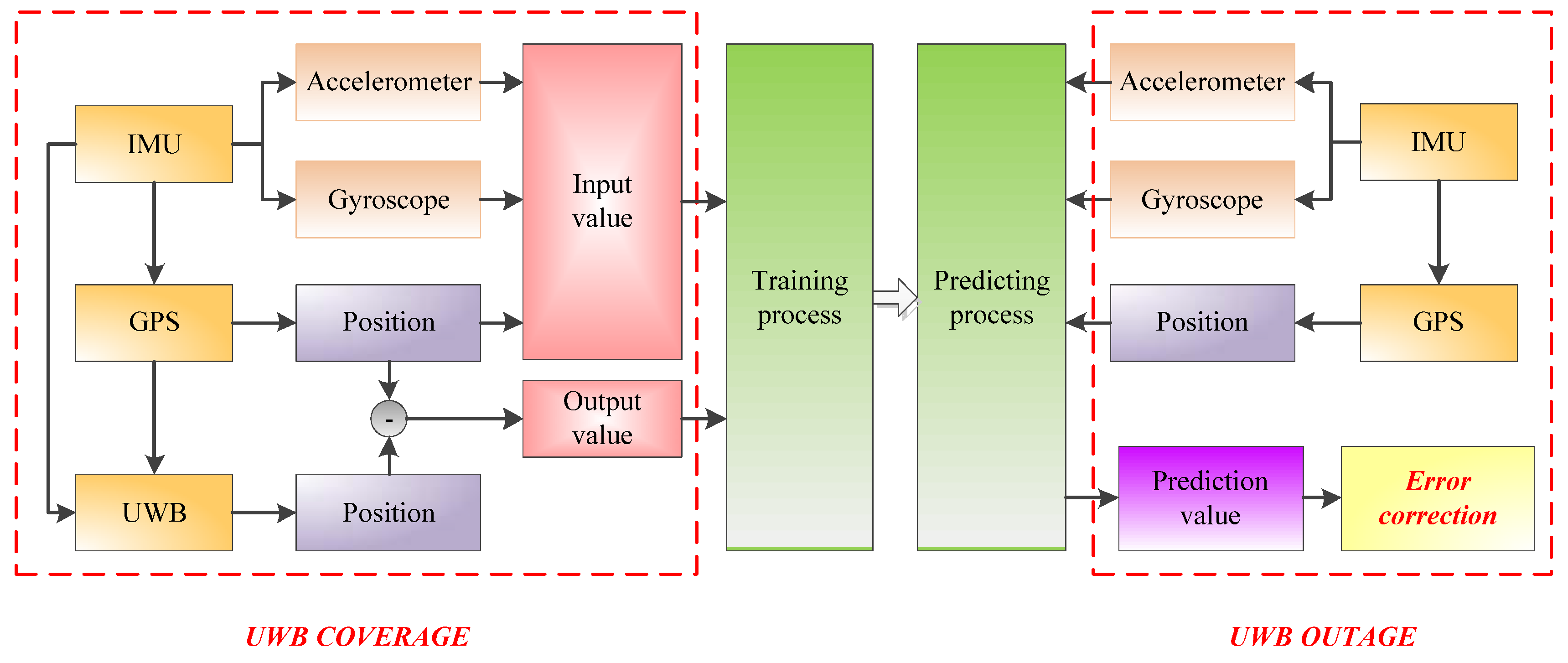
3. Position Error Correction under UWB Outages Conditions

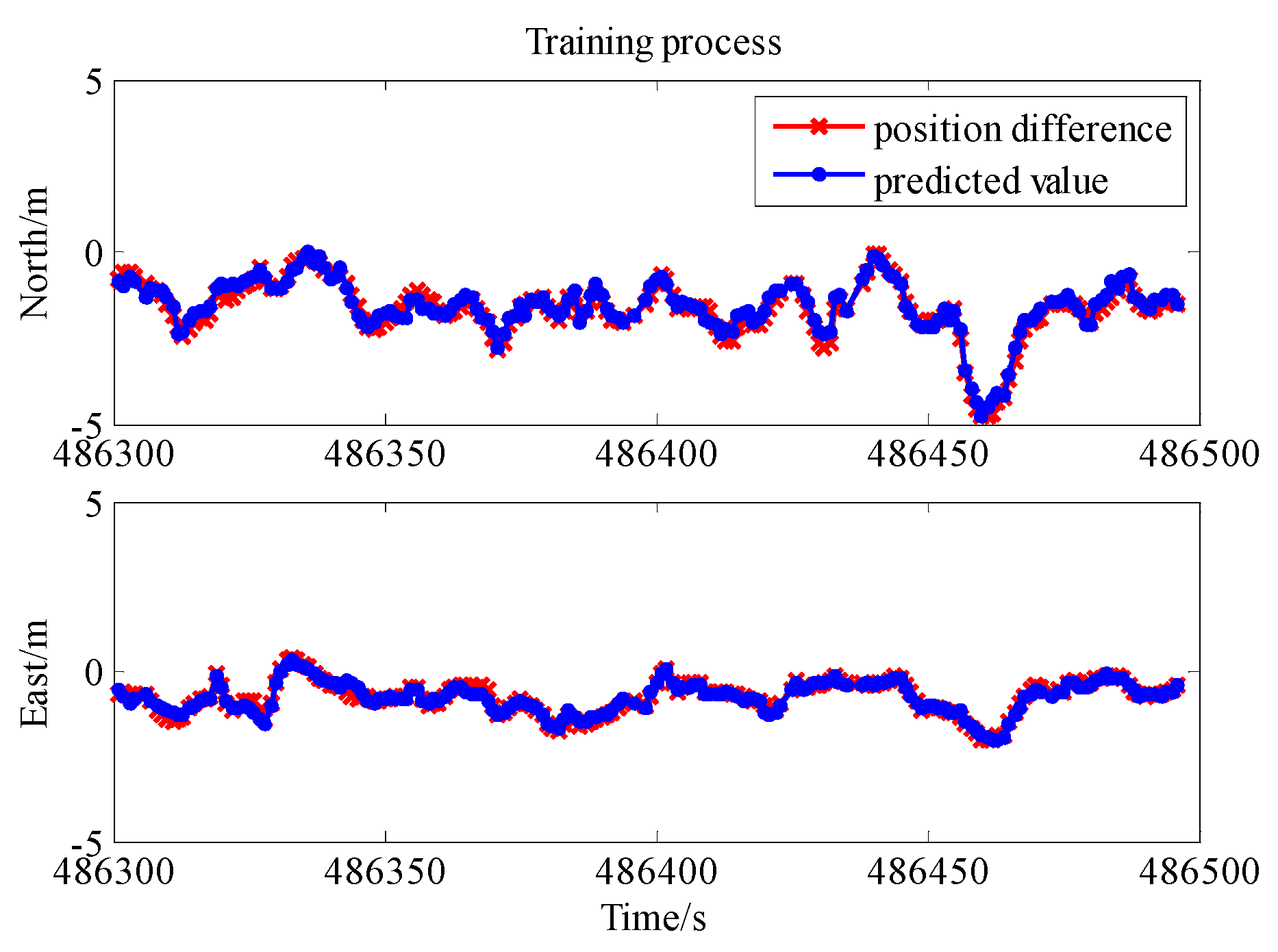
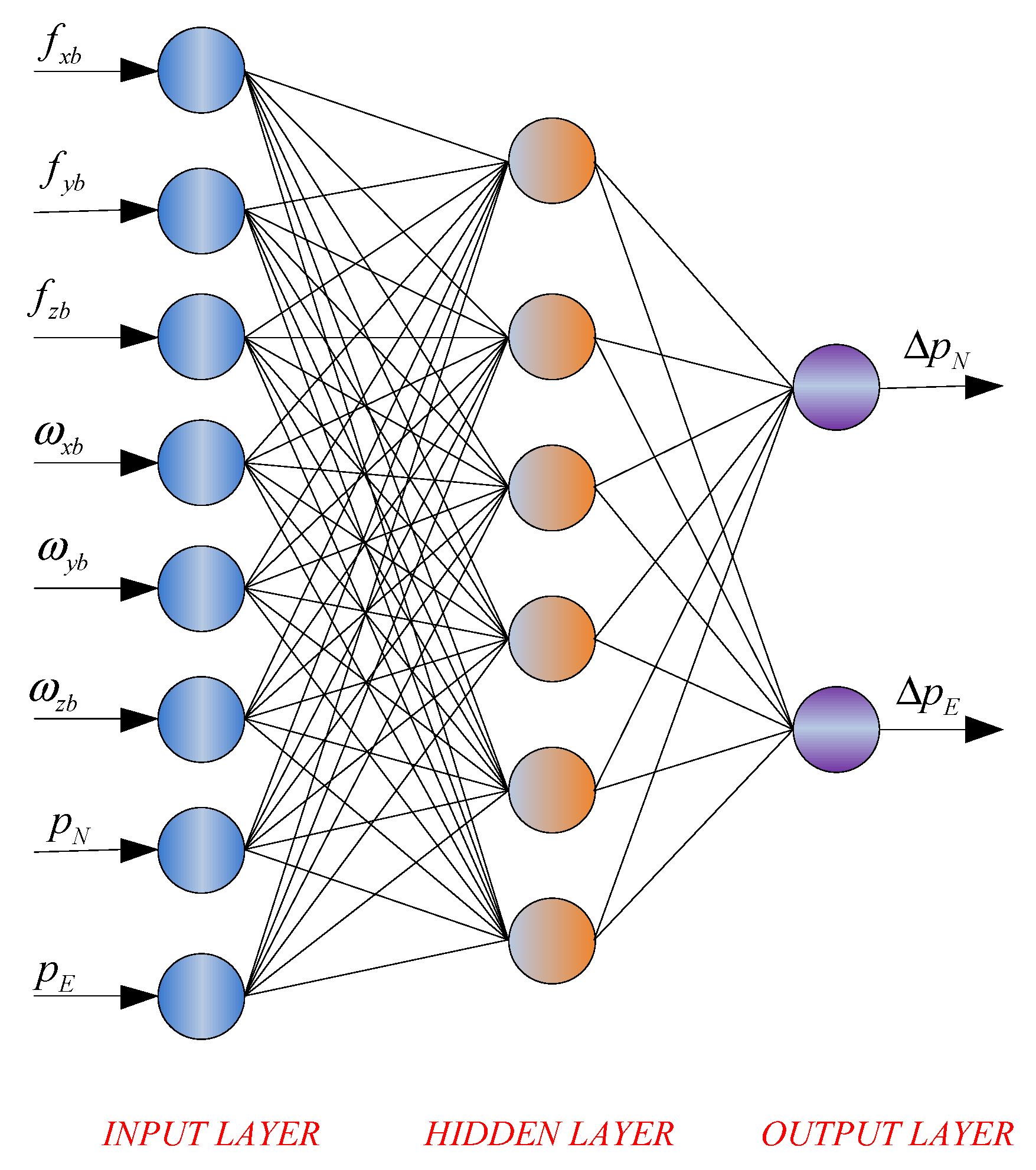
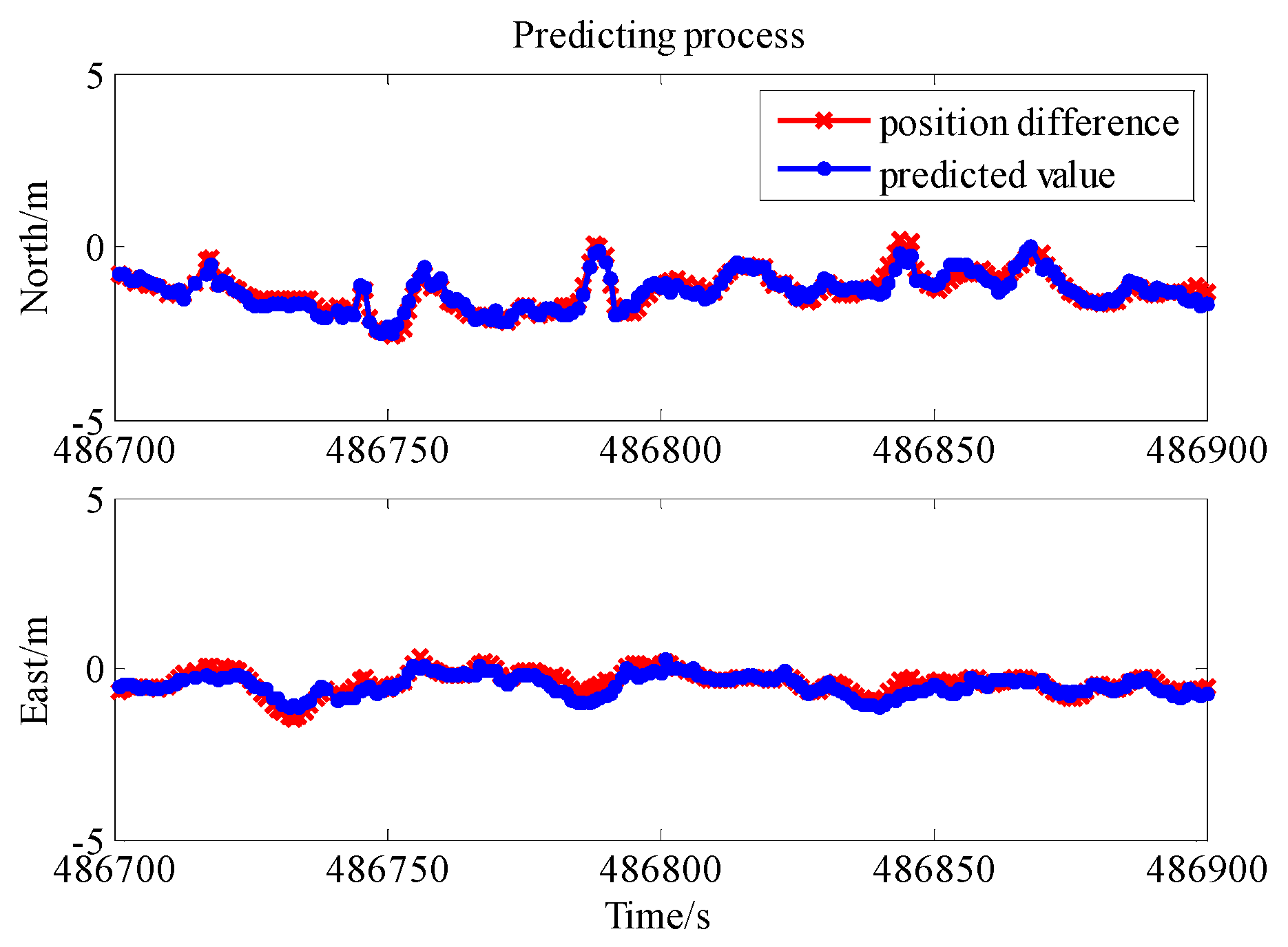
3.1. Position Error Prediction with UWB Observation

Many machine-learning methods can be used to predict position differences between a GPS/INS integrated solution and a GPS/INS/UWB integrated solution when the UWB signal is unavailable. In this case, the fuzzy neural network (FNN) method is used as example [24]. Because the machine-learning method requires data to train neurons to perform estimates as close to accurate as possible, our GPS/INS/UWB integrated system records the inertial measurement unit (IMU) observation and position solution by GPS/INS integrated system as the input. The output between the GPS/INS integrated position and the GPS/INS/UWB integrated position is a 2-D vector with north and east positions as components (Figure 1). Most often, the UWB signal emitter is installed close to the ground and UWB range observation is insensitive to the height. Therefore, it is difficult to modify errors in the height direction, and the output of machine learning excludes this information.
Figure 2 illustrates the machine-learning system configuration and training strategy. During the training phase, the position difference between the GPS/INS solution and the GPS/INS/UWB solution is selected as the target for network training during UWB signal availability. Thus, on the one hand, the navigational knowledge can be determined and amassed. Otherwise, if the network is well trained and the UWB signal is unavailable, the constructed model receives the rotation rates and acceleration from INS and the position from the GPS/INS integrated system to generate the predication value of position difference between GPS/INS solution and GPS/INS/UWB solution. The predication value is regarded as the error correction value for GPS/INS integrated navigation.

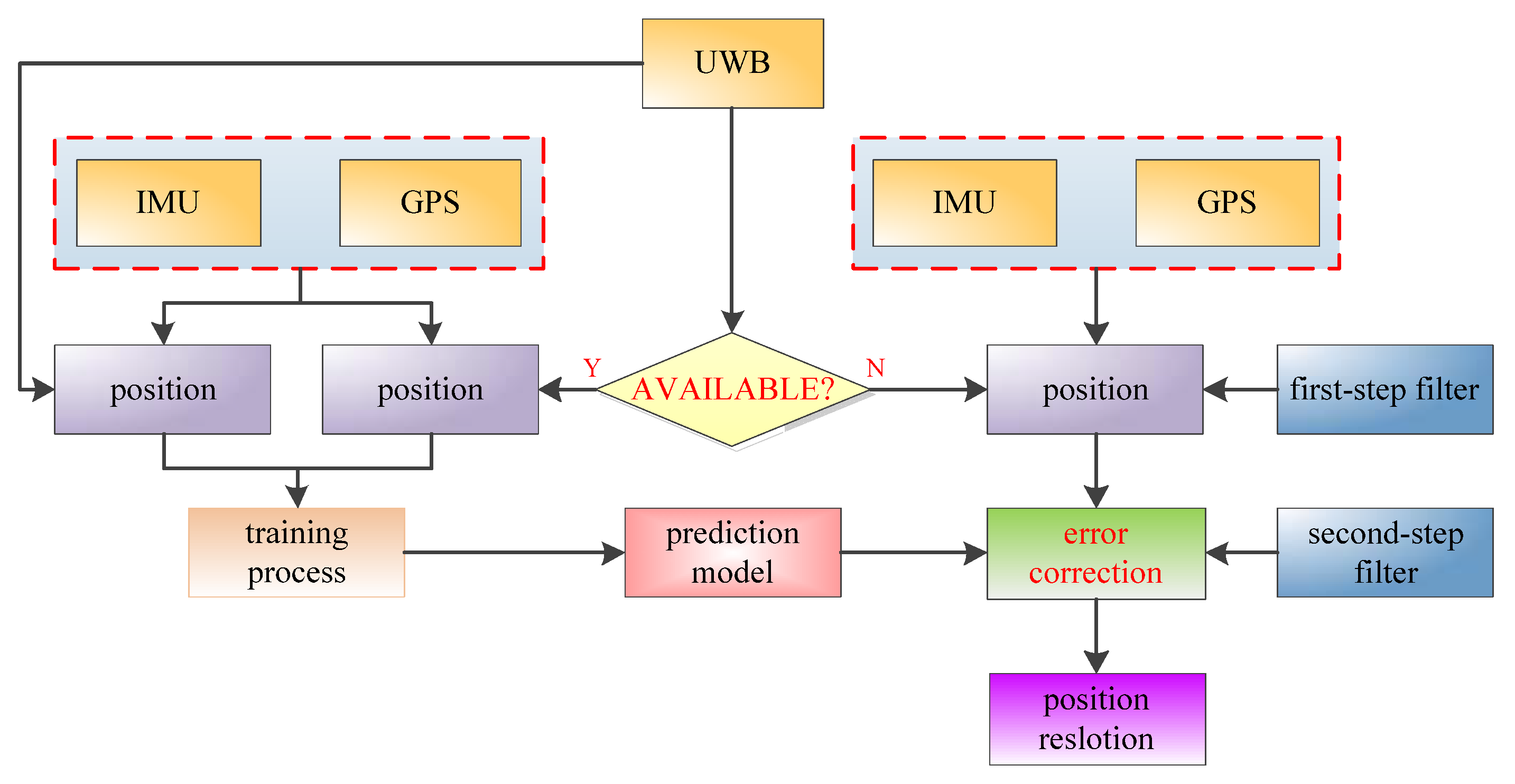
3.2. Position Error Correction Scheme with Two-Step Filter

Position error correction is used to improve the accuracy of GPS/INS/UWB integrated navigation when UWB is unavailable. When the UWB signal is on, the difference in the position solution between the GPS/INS system and GPS/INS/UWB system is used to construct the prediction model which is able to realize the correction calculation. When UWB is unavailable, GPS and INS are integrated to compute the navigation information with a Kalman filter. This is the first-step Kalman filter. The filter observations are the pseudo-range and Doppler value observed by GPS. Then the correction information is calculated by the above prediction model in Figure 2 and input to the second-step filter as the filter observation to update the position solution calculated by GPS/INS integrated navigation (Figure 3). Rather than modifying the position result with error correction information directly, the two-filter mode is able to avoid the filter divergence.
The observation model of the position error correction is composed of:
Z = [ Δ p N Δ p E ]
where Δ p N and Δ p E are the position differences between the GPS/INS integrated solution and the GPS/INS/UWB integrated solution. The position difference information is calculated by the machine learning method and employed to improve the position accuracy during UWB unavailability.

4. Field Test and Analysis

We field-tested the system on the roof of the Nottingham Geospatial Institute (NGI; Nottingham, UK). Our field test system included one tactical-grade IMU, three UWB units, one MEMS-grade IMU, and two GPS receivers. The UWB unit sampled information at one hertz. At the beginning of the test, we installed a Leica AS10 GNSS dual-frequency antenna at the top of a pillar above the NGI locomotive, and we fastened a UWB unit under the antenna using a lever-arm. Two UWB units were set on the pillars on the NGI roof, and the coordinates of the pillars were known. The distances r 1 UWB and r 2 UWB between the locomotive and the pillars were measured by the UWB system. This UWB unit was connected to a laptop to store the range observations. The MEMS IMU inside the locomotive was connected to the Leica antenna. It recorded raw observations onto a SD card for post-processing. Another GPS receiver was set on a pillar on the NGI roof to serve as a reference station for calculating DGPS corrections. The UWB ranges were time-tagged by the laptop, which was synchronized to the GPS time, to collect one-hertz UWB ranges prior to testing. The sampling rate of GPS receivers and IMU were respectively configured as 10 Hz and 200 Hz [27].
The duration of the whole test lasted about 15 min. The GPS observations were processed using GPS software GrafNavTM 8.0 in RTK mode by phase differences. The solution was regarded as the position reference. The accuracy of position reference reached centimeter-level. The initial standard deviation of pseudorange, Doppler and UWB observations were 2.5 m, 0.1 m/s and 0.3 m using their prior statistical data. The experience trajectory and the devices used during the tests are presented in Figure 4 and Figure 5 [28]. The velocity series of the NGI locomotive during the field test are presented in Figure 6. The specifications of the MEMS-IMU are given in Table 1.
In order to test the performance of the enhanced GPS/INS/UWB integrated system, the whole trajectory was divided into three stages:
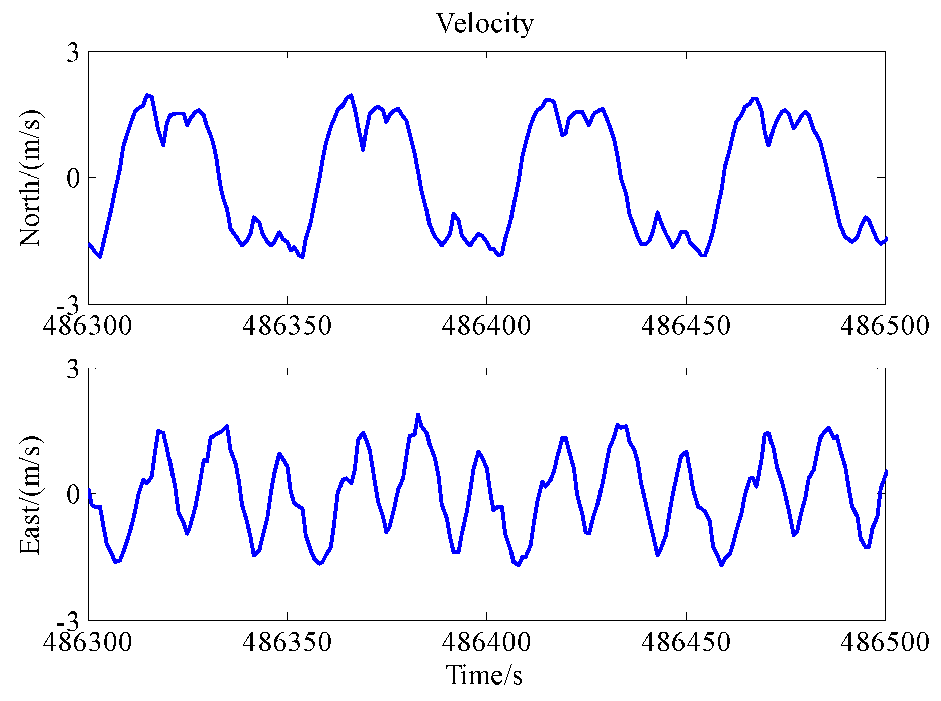
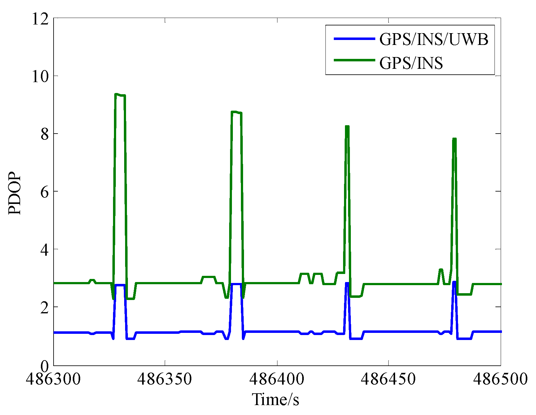
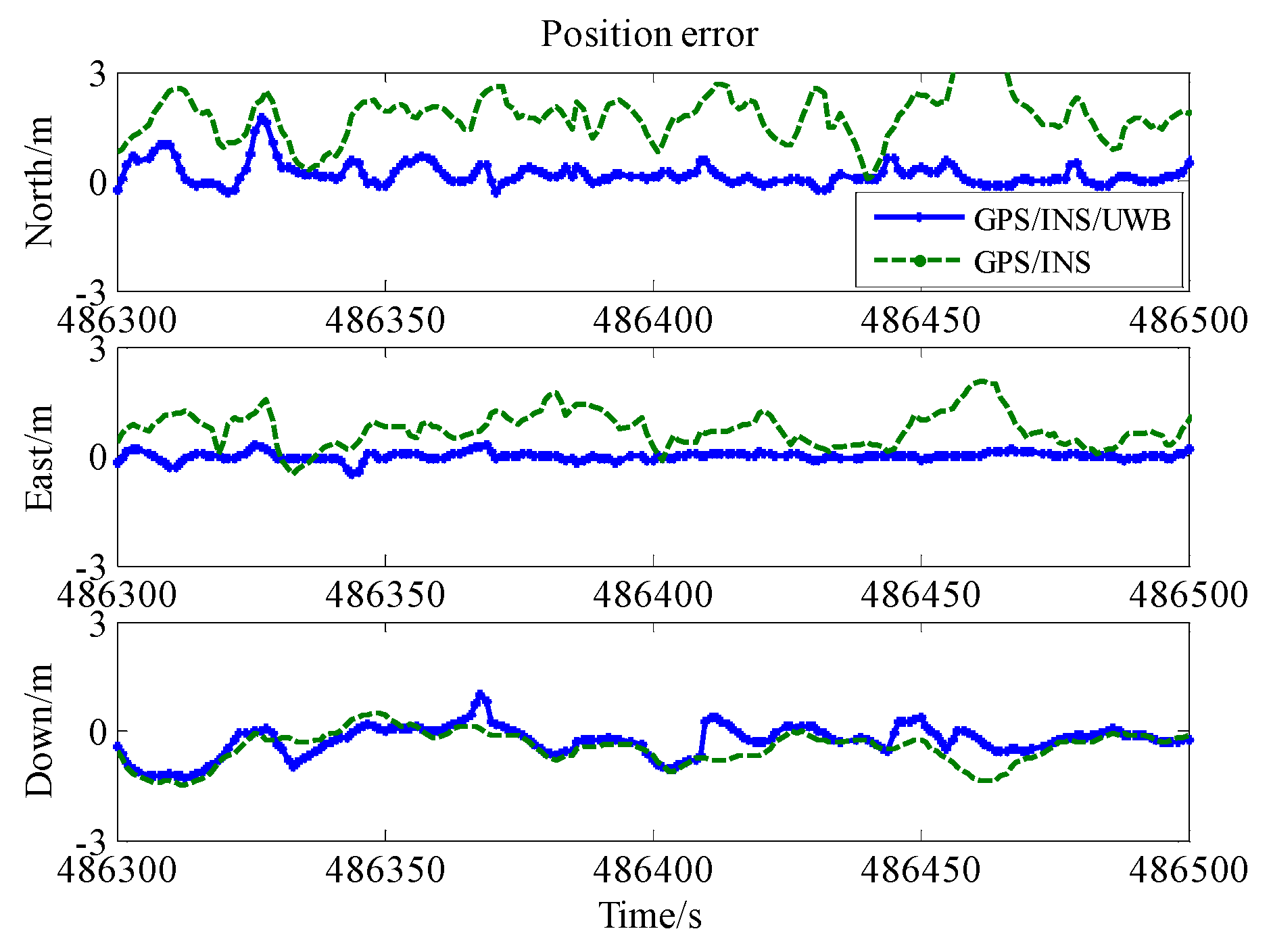
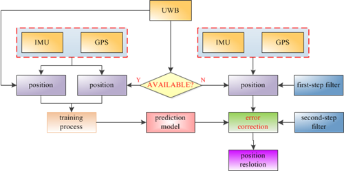
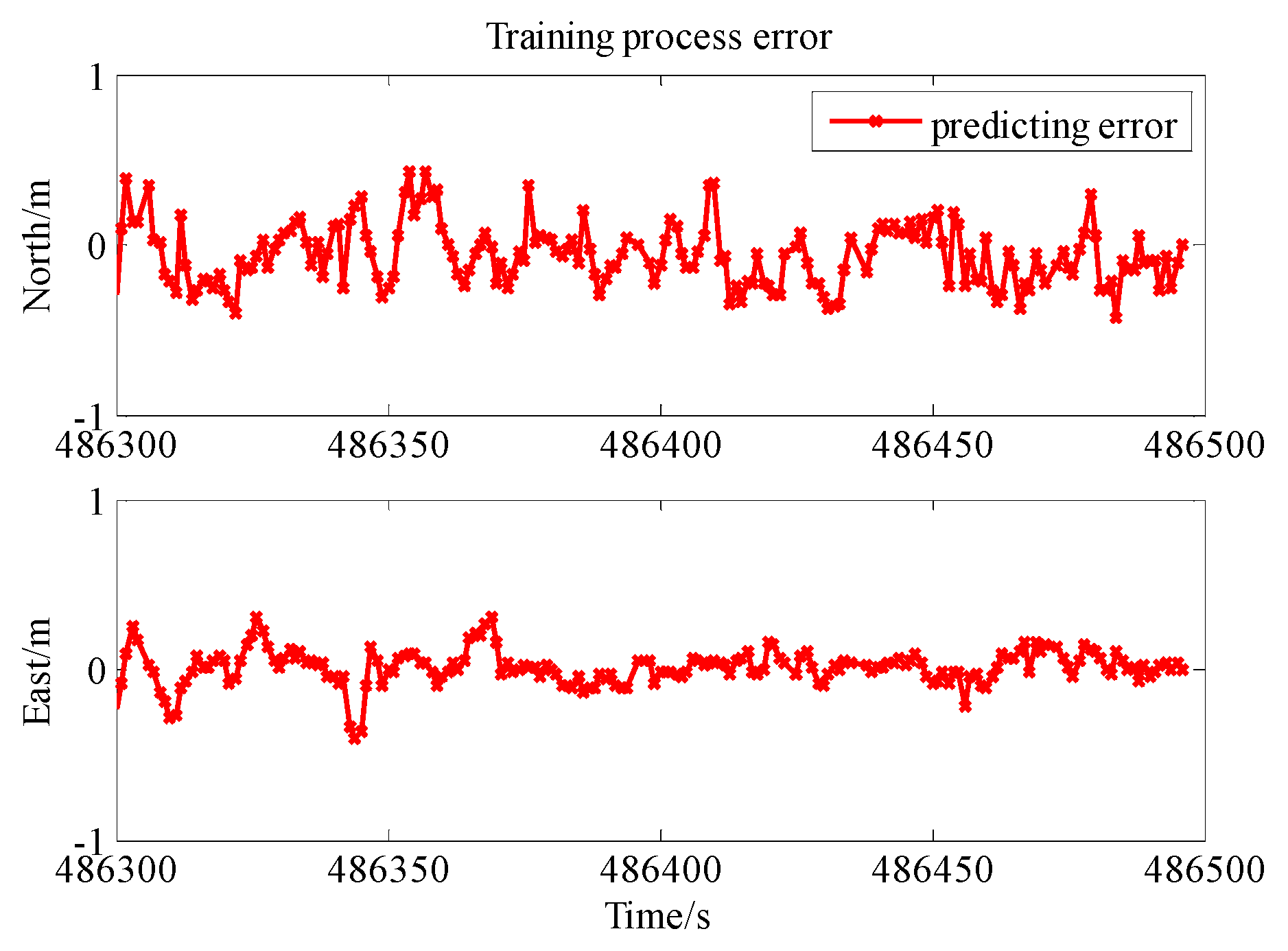
  • Stage one: The UWB signal is available and GPS, INS and UWB are integrated from 486,300 s to 486,500 s.
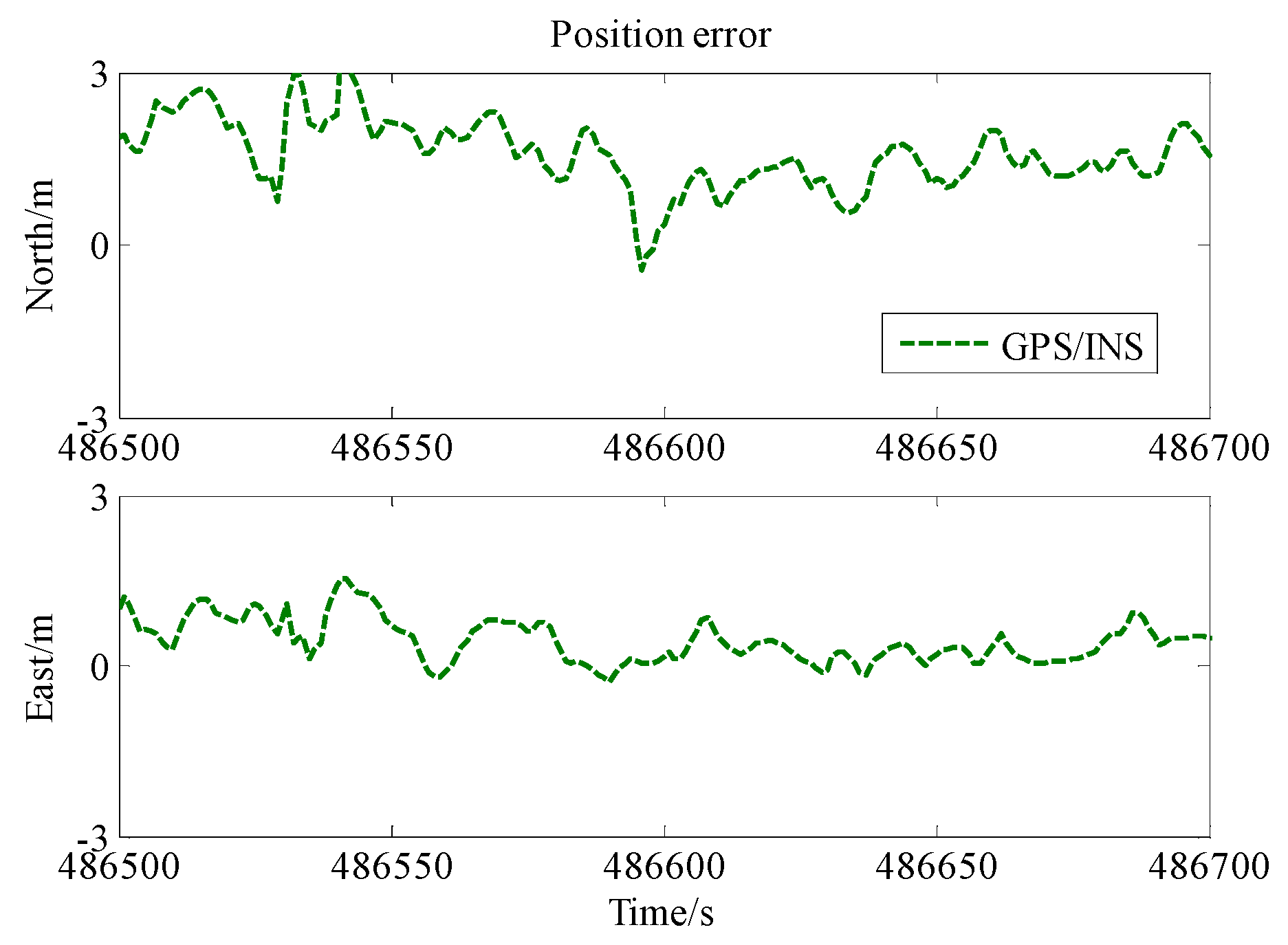
  • Stage two: The UWB signal is unavailable and GPS and INS are integrated without error correction from 486,500 s to 486,700 s.
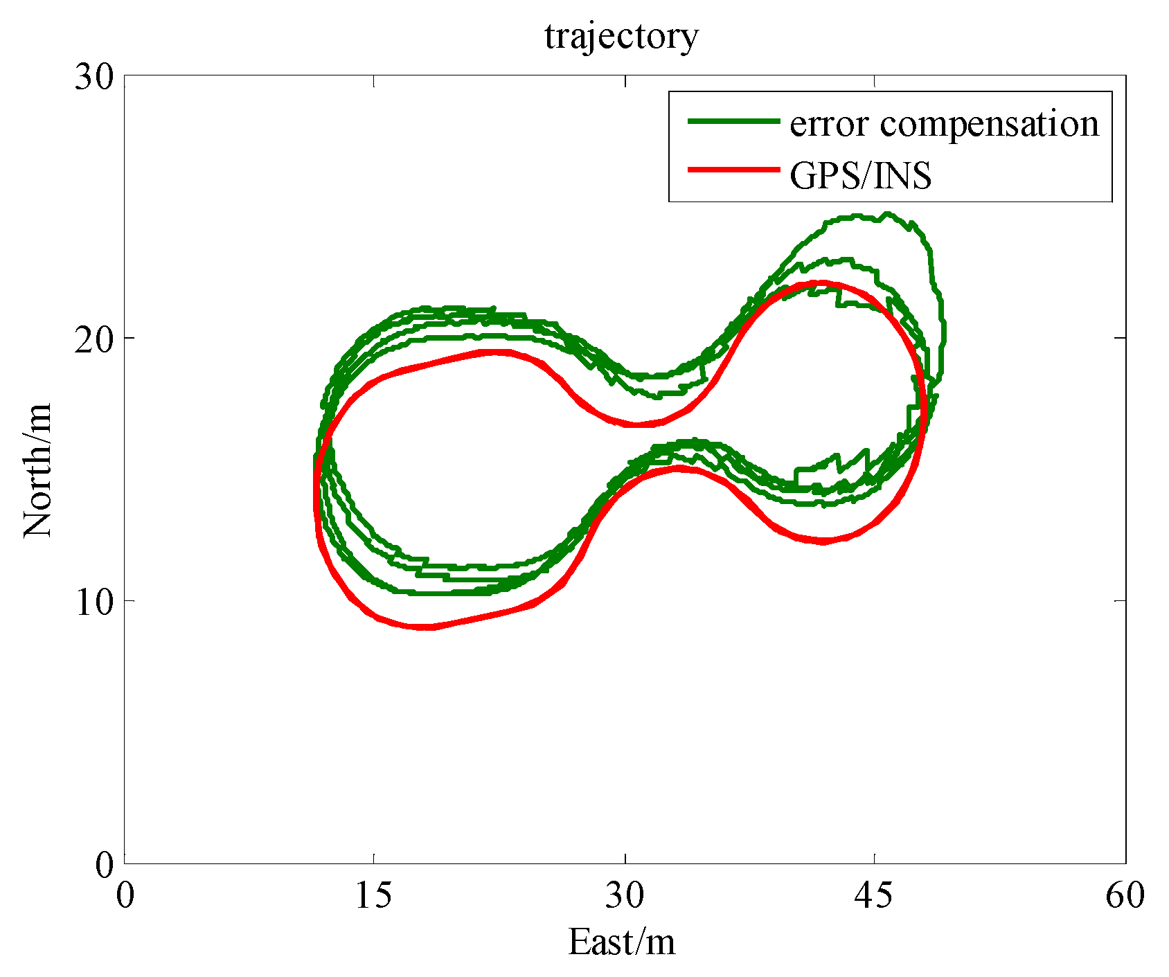
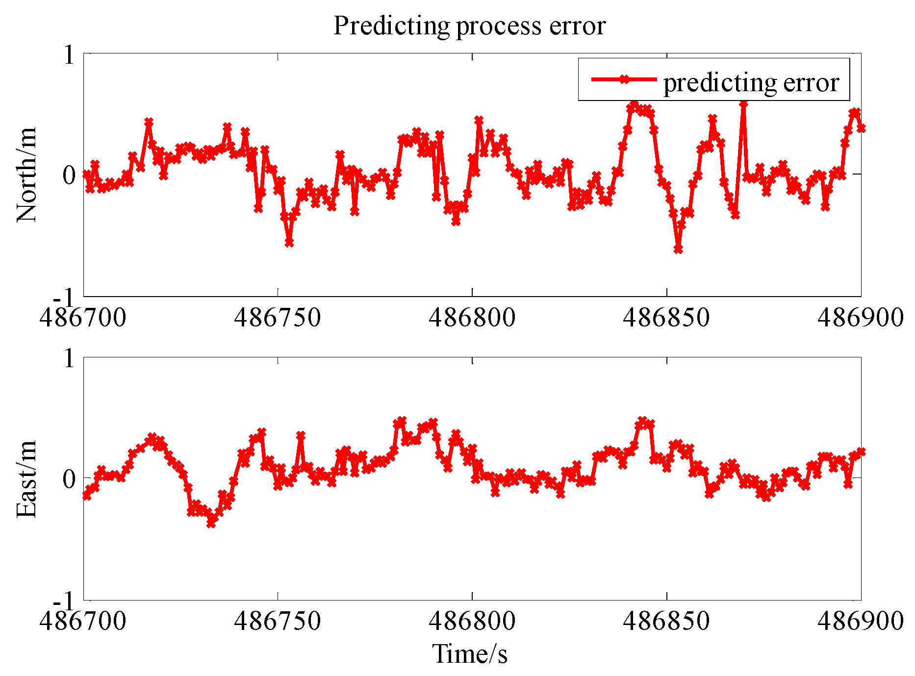
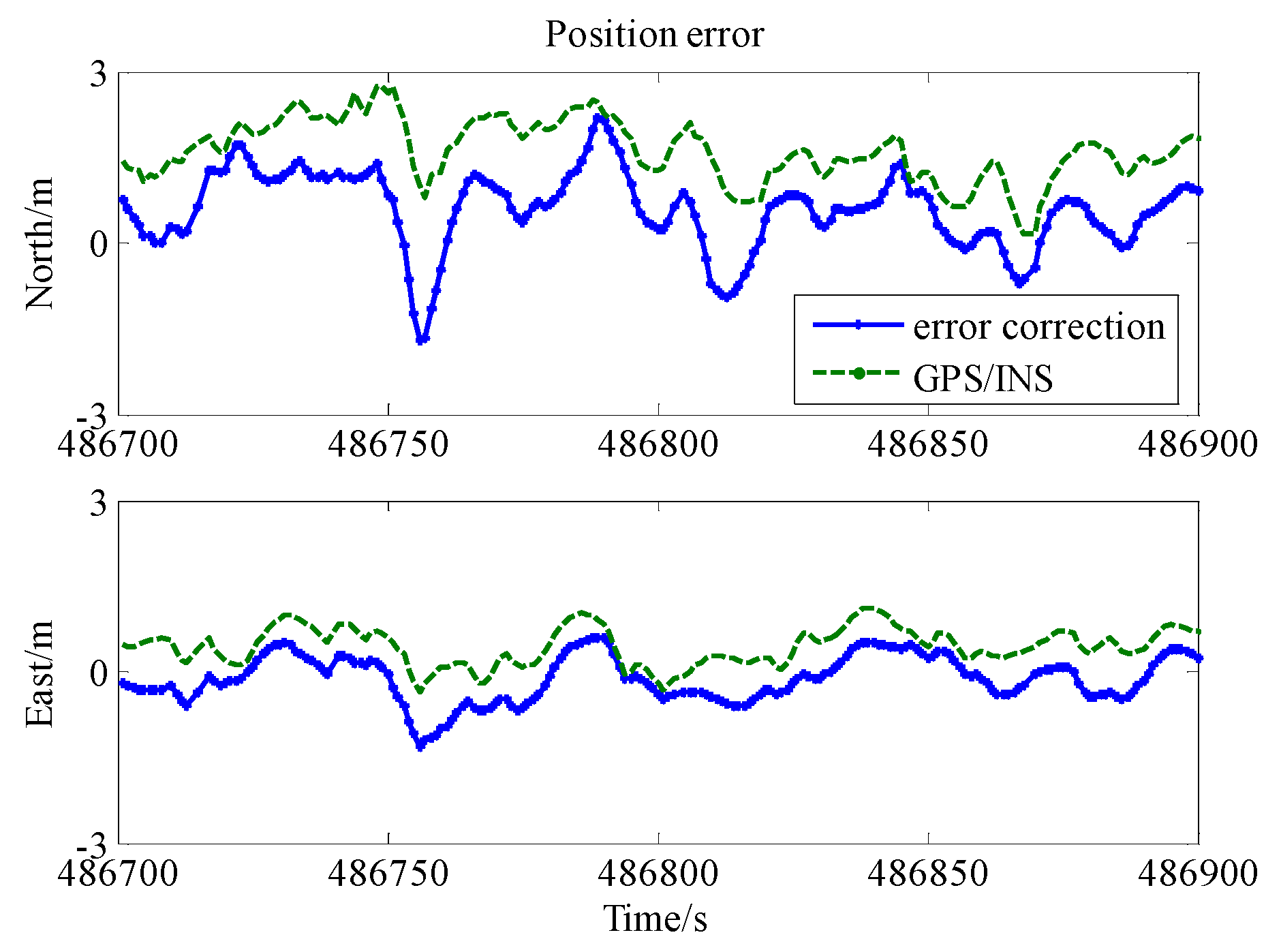
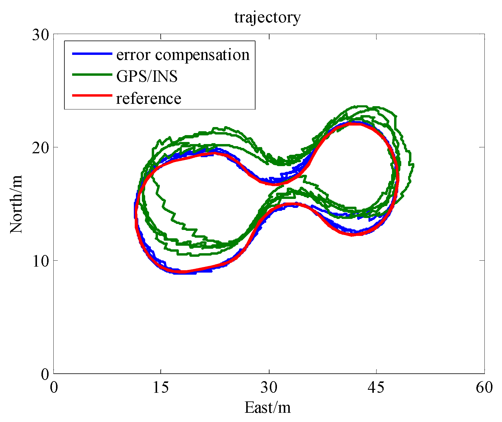
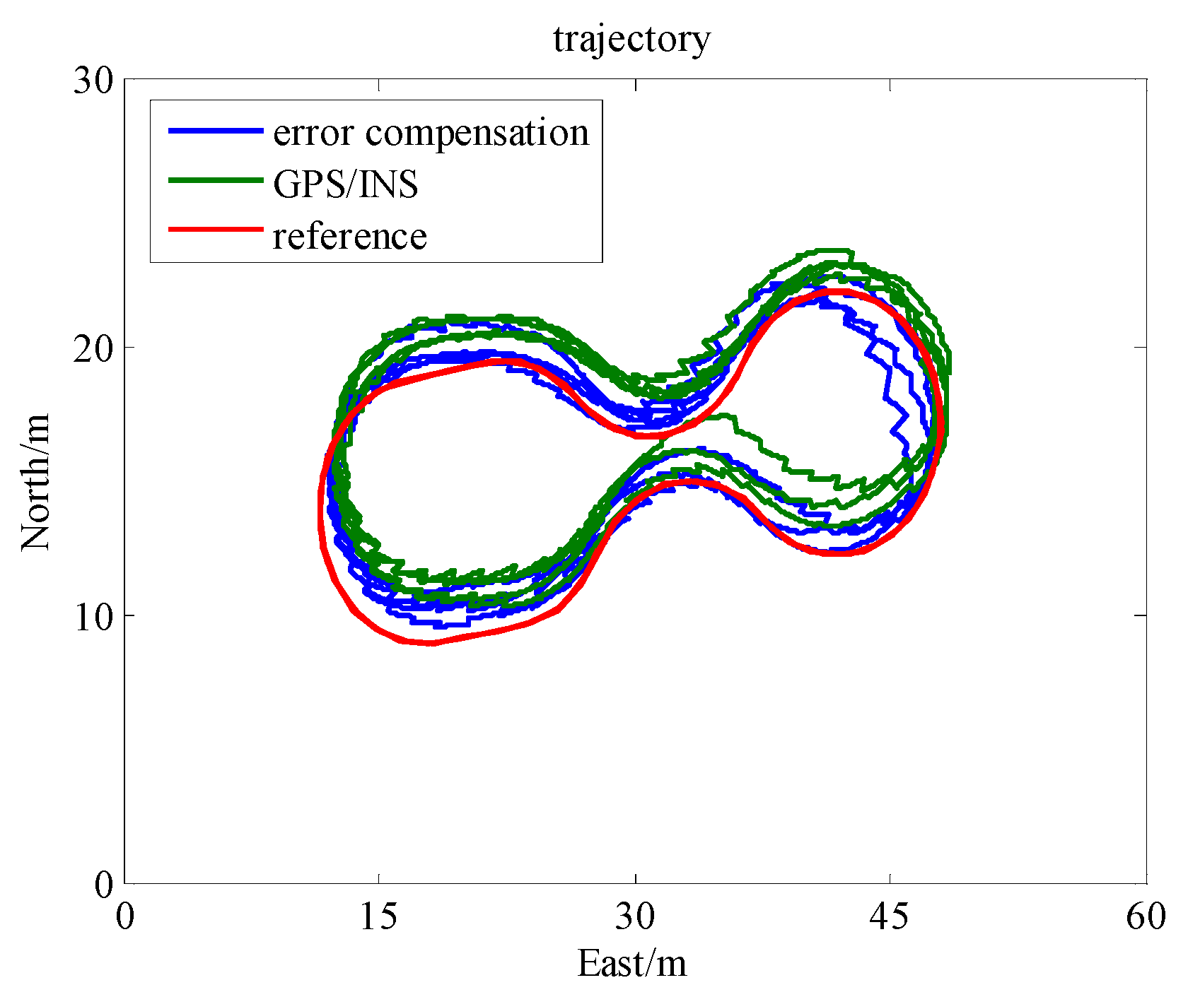
  • Stage three: The UWB signal is unavailable and GPS and INS are integrated with error correction scheme presented in Section 3 from 486,700 s to 486,900 s.
The field test trajectories of GPS/INS integrated navigation with and without UWB observation in stage one are shown in Figure 7. Figure 8 shows the comparison of PDOP (Position Dilution of Precision) value between GPS/INS and GPS/UWB/INS tightly coupled navigation. Figure 9 shows the time series of position errors in the north, east and down directions for two schemes. Table 2 summarizes the root mean square (RMS) and MEAN of position error for the two schemes during this period of the test. The GPS/INS integrated solutions were not good, with error RMS of 2.00 m, 0.89 m and 0.65 m in the north, east and down directions, respectively. However, when adding UWB data, the solution is improved by 82%, 88% and 14%, respectively. It can be seen that the accuracy improvement in the east and north directions were much larger than that in the down direction. The accuracy improvement in height can be lower than 14%. So the output of the machine learning excludes the position information in the height.
Figure 10 depicts the training results of two parameters (position difference in north and east direction) in stage two. The legend ‘position difference’ represents the real difference between GPS/INS and GPS/INS/UWB integrated solutions, in which the legend ‘predicted value’ represents the position difference predicted in the training process by the method in Figure 2. The predicted value of the position difference was very close to the real value. Shown in Figure 11 are north and east errors of position differences between the GPS/INS and the GPS/INS/UWB integrated solution in the training process. Still, the two-dimensional RMS for both directions was somewhat low and below half-meter, which was 19 cm in the north direction and 12 cm in the east direction for RMS of the training result error. Training results showed that the method displayed in Figure 2 had a good performance for estimating the position difference.
The trajectory of GPS/INS integrated navigation is shown in Figure 12 with a duration from 486,500 s to 486,700 s. Figure 13 shows the time series of position errors in the north and east directions for GPS/INS integrated navigation. The UWB information and error correction method are not employed during this time. It is obvious that the trajectory of the GPS/INS integrated navigation without error correction seriously deviated from the reference. The error RMS reaches up to 1.68 m and 0.68 m in the north and east directions, respectively.
In the duration from 486,700 s to 486,900 s, we applied the constructed model to predict the position difference between the GPS/INS and GPS/INS/UWB integrated solutions. Figure 14 provides the prediction results. The legend ‘predicted value’ represents the position difference predicted by the method as shown in Figure 2. Shown in Figure 15 are north and east errors of position differences between GPS/INS and GPS/INS/UWB integrated solution in the predicting process. As in the training phase, still the 2D RMSE for both directions is somewhat low and below one meter, which was 26 cm in the north direction and 18 cm in the east direction for RMS of the training result error. Prediction results showed that the method in Figure 2 offers a good performance for estimating the position difference. It can be noticed that the error of the predicted value is much smaller than the position error of GPS/INS integrated navigation. The proposed scheme learned the error behavior of GPS/INS/UWB integrated navigation well during the UWB signal outage.
Figure 16 shows a field test trajectory comparison for different schemes in stage three. Because the UWB signal is unavailable, only GPS and INS were integrated to calculate the navigation information. The error correction method proposed in the paper is employed in the GPS/INS integrated navigation system (UWB signal outage). Figure 17 shows the time series of position errors in the east and north directions for the GPS/INS integrated system with and without error correction. Table 3 illustrates the RMS and MEAN of the position error of the data set from 486,700 s to 486,900 s for two schemes. When the proposed error correction method was used, the RMS of position errors in the north and east direction were 0.89 m and 0.42 m, respectively. On the contrary, the RMS of position errors were 1.70 m and 0.55 m, respectively, when the error correction method was not applied. Based on the analytical and experimental results, the GPS/INS integrated navigation with error correction outperformed the GPS/INS integrated navigation by 48% and 23% in the north and east directions, respectively. It clearly illustrates that the proposed error correction algorithm is able to improve the accuracy of GPS/INS integrated navigation.

5. Conclusions

An enhanced GPS/INS/UWB integrated scheme with positioning error correction is proposed to improve the position accuracy, which is based on predicting the position difference between GPS/INS solution and GPS/INS/UWB solution in the UWB outage scenario. The functionality and performance of the proposed method has been verified. It was also compared with the GPS/INS integrated navigation using a single-point-positioning mode with pseudo-range observation.
Based on the ability of UWB observations to enhance the position accuracy of GPS/NS integrated navigation, the proposed method taps the potential of UWB information observed before when the UWB signal is unavailable. The solution of the enhanced GPS/INS/UWB integrated scheme maintains sub-meter accuracy during the whole test, even in the case of UWB signal outage. In contrast, the GPS/INS integrated system only results in accuracy of one to two meters due to the large deviation of the single-point-positioning mode. A position error correction algorithm would help to improve the solution accuracy. Based on analytical and experimental results, the GPS/INS/UWB integrated navigation with error correction outperforms the GPS/INS integrated navigation by 48% and 23% in the north and east directions, respectively, when the UWB signal is unavailable.
The integrated positioning method based on a multi-sensor is able to realize the integration of advantages from different sensors. The ability of UWB was tapped further in the proposed method, but the cooperative level of different sensors was also not high, such as the modification of system error from the UWB observation and robustness of the original observation. In our future work, the potential of cooperative work for the multi-sensor and more application conditions will be investigated.
The position error of integrated systems is mainly influenced by the state of motion and the environment. The input value of machine-learning only reflected the state of motion, because it is difficult to evaluate the motion environment quantitatively. Thus, the performance of the proposed method is best if the vehicle is always on the same route. When the road environment has changed, the performance will become worse. The construction of a more appropriate model considering the state of motion and environment is therefore the next step in our research work.

Acknowledgments

The work is partially sponsored by the National Key Research and Development Program of China (grant number: 2016YFB0502102), partially sponsored by National Natural Science Foundation of China (grant number: 41604006, 41674030) and partially sponsored by Natural Science Foundation of Jiangsu Province (grant number: BK20160247). The authors would like to thank Xiaolin Meng and all the experience members in the University of Nottingham, as well as helping with the collection and processing of the field test data.

Author Contributions

The author Zengke Li proposed the research idea with the author Ren Wang, carried out most of the experimental work, and drafted the manuscript. The author Jingxiang Gao performed data analysis and was responsible for field data collection. The corresponding author Ren Wang, who is responsible for the overall work, conducted the experiment part, involved in the algorithm design. The author Jian Wang was involved in the write-up of the manuscript and the collection of the field test data.

Conflicts of Interest

The authors declare no conflict of interest.

References

  1. Nassar, S.; El-Sheimy, N. A combined algorithm of improving INS error modeling and sensor measurements for accurate INS/GPS navigation. GPS Solut. 2006, 10, 29–39. [Google Scholar] [CrossRef]
  2. Teunissen, P.; Odolinski, R.; Odijk, D. Instantaneous BeiDou+GPS RTK positioning with high cut-off elevation angles. J. Geod. 2014, 88, 335–350. [Google Scholar] [CrossRef]
  3. Odolinski, R.; Teunissen, P.J.; Odijk, D. Combined BDS, Galileo, QZSS and GPS single-frequency RTK. GPS Solut. 2015, 19, 151–163. [Google Scholar] [CrossRef]
  4. Wübbena, G.; Schmitz, M.; Bagge, A. PPP-RTK: Precise point positioning using state-space representation in RTK networks. In Proceedings of the 18th International Technical Meeting of the Satellite Division of The Institute of Navigation, Long Beach, CA, USA, 13–16 September 2005. [Google Scholar]
  5. Teunissen, P.; Khodabandeh, A. Review and principles of PPP-RTK methods. J. Geod. 2015, 89, 217–240. [Google Scholar] [CrossRef]
  6. Li, X.; Zhang, X.; Ge, M. Regional reference network augmented precise point positioning for instantaneous ambiguity resolution. J. Geod. 2011, 85, 151–158. [Google Scholar] [CrossRef]
  7. Geng, J.; Teferle, F.N.; Meng, X.; Dodson, A. Towards PPP-RTK: Ambiguity resolution in real-time precise point positioning. Adv. Space Res. 2011, 47, 1664–1673. [Google Scholar] [CrossRef]
  8. Kubo, N.; Hou, R.; Suzuki, T. Decimeter level vehicle navigation combining multi-GNSS with existing sensors in dense urban areas. In Proceedings of the 2014 International Technical Meeting of The Institute of Navigation, San Diego, CA, USA, 27–29 January 2014. [Google Scholar]
  9. MacGougan, G.; O’Keefe, K. Real time UWB error estimation in a tightly-coupled GPS/UWB positioning system. In Proceedings of the 2009 International Technical Meeting of The Institute of Navigation, Anaheim, CA, USA, 26–28 January 2009. [Google Scholar]
  10. MacGougan, G.; O’Keefe, K.; Chiu, D. Multiple UWB range assisted GPS RTK in hostile environments. In Proceedings of the 21st International Technical Meeting of the Satellite Division of The Institute of Navigation (ION GNSS 2008), Savannah, GA, USA, 16–19 September 2008. [Google Scholar]
  11. MacGougan, G.; O’Keefe, K.; Klukas, R. Accuracy and reliability of tightly coupled GPS/ultra-wideband positioning for surveying in urban environments. GPS Solut. 2010, 14, 351–364. [Google Scholar] [CrossRef]
  12. De Angelis, A.; Nilsson, J.; Skog, I.; Händel, P.; Carbone, P. Indoor positioning by ultrawide band radio aided inertial navigation. Metrol. Meas. Syst. 2010, 17, 447–460. [Google Scholar] [CrossRef]
  13. MacGougan, G.; O’Keefe, K.; Klukas, R. Tightly-coupled GPS/UWB integration. J. Navig. 2010, 63, 1–22. [Google Scholar] [CrossRef]
  14. Jiang, Y.; Petovello, M.; O’Keefe, K.; Basnayake, C. Augmentation of carrier-phase DGPS with UWB ranges for relative vehicle positioning. In Proceedings of the 25th International Technical Meeting of The Satellite Division of the Institute of Navigation (ION GNSS 2012), Nashville, TN, USA, 17–21 September 2012. [Google Scholar]
  15. Petovello, M.G.; O’Keefe, K.; Chan, B.; Spiller, S.; Pedrosa, C.; Xie, P.; Basnayake, C. Demonstration of inter-vehicle UWB ranging to augment DGPS for improved relative positioning. J. Glob. Position Syst. 2012, 11, 11–21. [Google Scholar] [CrossRef]
  16. Wang, D.; O’Keefe, K.; Petovello, M.G. Decentralized cooperative navigation for vehicle-to-vehicle (V2V) applications using GPS integrated with UWB range. In Proceedings of the ION 2013 Pacific PNT Meeting, Honolulu, HI, USA, 23–25 April 2013. [Google Scholar]
  17. Gross, J.N.; Yu, G. Dewberry Brandon Tightly-coupled GPS/UWB-ranging for relative navigation during formation flight. In Proceedings of the 27th International Technical Meeting of The Satellite Division of the Institute of Navigation (ION GNSS+ 2014), Tampa, FL, USA, 8–12 September 2014. [Google Scholar]
  18. Gao, Y.; Meng, X.; Hancock, C.M.; Stephenson, S.; Zhang, Q. UWB/GNSS-based cooperative positioning method for V2X applications. In Proceedings of the 27th International Technical Meeting of The Satellite Division of the Institute of Navigation (ION GNSS+ 2014), Tampa, FL, USA, 8–12 September 2014. [Google Scholar]
  19. Dierenbach, K.; Ostrowski, S.; Jozkow, G.; Toth, C.K.; Grejner-Brzezinska, D.A.; Koppanyi, Z. UWB for Navigation in GNSS Compromised Environments. In Proceedings of the 28th International Technical Meeting of The Satellite Division of the Institute of Navigation (ION GNSS+ 2015), Tampa, FL, USA, 14–18 September 2015. [Google Scholar]
  20. Tanigawa, M.; Hol, J.D.; Dijkstra, F.; Luinge, H.; Slycke, P. Augmentation of low-cost GPS/MEMS INS with UWB positioning system for seamless outdoor/indoor positioning. In Proceedings of the 21st International Technical Meeting of the Satellite Division of The Institute of Navigation (ION GNSS 2008), Savannah, GA, USA, 16–19 September 2008. [Google Scholar]
  21. Vydhyanathan, A.; Luinge, H.; Tanigawa, M.; Dijkstra, F.; Braasch, M.S.; de Haag, M.U. Augmenting low-cost GPS/INS with ultra-wideband transceivers for multi-platform relative navigation. In Proceedings of the 22nd International Technical Meeting of The Satellite Division of the Institute of Navigation (ION GNSS 2009), Savannah, GA, USA, 22–25 September 2009. [Google Scholar]
  22. Ascher, C.; Zwirello, L.; Zwick, T.; Trommer, G. Integrity monitoring for UWB/INS tightly coupled pedestrian indoor scenarios. In Proceedings of the 2011 International Conference on Indoor Positioning and Indoor Navigation (IPIN), Guimaraes, Portugal, 21–23 September 2011. [Google Scholar]
  23. Shen, F.; Cheong, J.W.; Dempster, A.G. An ultra-wide bandwidth-based range/GPS tight integration approach for relative positioning in vehicular ad hoc networks. Meas. Sci. Technol. 2015, 26, 045003. [Google Scholar] [CrossRef]
  24. Li, Z.; Wang, J.; Li, B.; Gao, J.; Tan, X. GPS/INS/Odometer integrated system using fuzzy neural network for land vehicle navigation applications. J. Navig. 2014, 67, 967–983. [Google Scholar] [CrossRef]
  25. Angrisano, A. GNSS/INS Integration Methods. Ph.D. Thesis, The University of Calgary, Calgary, AB, Canada, 2010. [Google Scholar]
  26. Yao, Y.; Xu, X.; Zhu, C.; Chan, C.Y. A hybrid fusion algorithm for GPS/INS integration during GPS outages. Measurement 2017, 103, 42–51. [Google Scholar] [CrossRef]
  27. Wang, J.; Gao, Y.; Li, Z.; Meng, X.; Hancock, C.M. A tightly-coupled GPS/INS/UWB cooperative positioning sensors system supported by V2I communication. Sensors 2016, 16, 944. [Google Scholar] [CrossRef] [PubMed]
  28. Stephenson, S.; Meng, X.; Moore, T.; Baxendale, A.; Edwards, T. Precision of network real time kinematic positioning for intelligent transport systems. In Proceedings of the European Navigation Conference, London, UK, 29 November–1 December 2011. [Google Scholar]
Figure 1. The construction of fuzzy neural network.
Remotesensing 10 00019 g001
Figure 2. Error correction prediction with ultra-wideband (UWB) observation.
Remotesensing 10 00019 g002
Figure 3. Position error correction scheme with two-step filter.
Remotesensing 10 00019 g003
Figure 4. Field test.
Remotesensing 10 00019 g004
Figure 5. The electric locomotive and test track.
Remotesensing 10 00019 g005
Figure 6. Velocity of locomotive.
Remotesensing 10 00019 g006
Figure 7. Field test trajectory comparison between Global Positioning System (GPS)/Inertial Navigation System (INS) and GPS/INS/UWB solution during UWB unblocking.
Remotesensing 10 00019 g007
Figure 8. PDOP value comparison between GPS/INS and GPS/UWB/INS tightly coupled navigation.
Remotesensing 10 00019 g008
Figure 9. Position error comparison between GPS/INS and GPS/INS/UWB solution in the north, east and down directions.
Remotesensing 10 00019 g009
Figure 10. The training results comparison between reference and prediction value in terms of position difference.
Remotesensing 10 00019 g010
Figure 11. The training results error of prediction value from 486,300 s to 486,500 s.
Remotesensing 10 00019 g011
Figure 12. Field test trajectory of GPS/INS integration navigation without UWB.
Remotesensing 10 00019 g012
Figure 13. Position error of GPS/INS integration navigation without UWB in the north and east directions.
Remotesensing 10 00019 g013
Figure 14. The predicting results comparison between reference and prediction value in terms of position difference.
Remotesensing 10 00019 g014
Figure 15. The error of prediction value using the proposed method in the north and east directions from 486,700 s to 486,900 s.
Remotesensing 10 00019 g015
Figure 16. Field test trajectory of GPS/INS integration navigation with error correction.
Remotesensing 10 00019 g016
Figure 17. Position error of GPS/INS integration navigation with error correction in the north and east directions.
Remotesensing 10 00019 g017
Table 1. Microelectromechanical system (MEMS)-grade inertial measurement unit (IMU) technical data.
ParametersGyroscopeAccelerometer
Initial bias error±0.25°/s±0.002 g
In-run bias stability18°/h±0.04 mg
Scale factor stability±0.05%±0.05%
Random walk0.03°/s/sqrt (Hz)80 µg/sqrt (Hz)
Table 2. Error RMS and MEAN comparison of different schemes in terms of position error.
SchemeRMS (m)MEAN (m)
NorthEastDownNorthEastDown
GPS/INS/UWB0.360.110.560.19−0.01−0.38
GPS/INS2.000.890.651.830.74−0.46
Table 3. Error RMS and MEAN comparison of different schemes in terms of position error.
SchemeRMS (m)MEAN (m)
NorthEastNorthEast
Error correction0.890.420.57−0.15
GPS/INS1.700.551.620.45

