Gen2 RFID-Based System Framework for Resource Circulation in Closed-Loop Supply Chains


Abstract
:1. Introduction
2. Related Studies and Current Situation
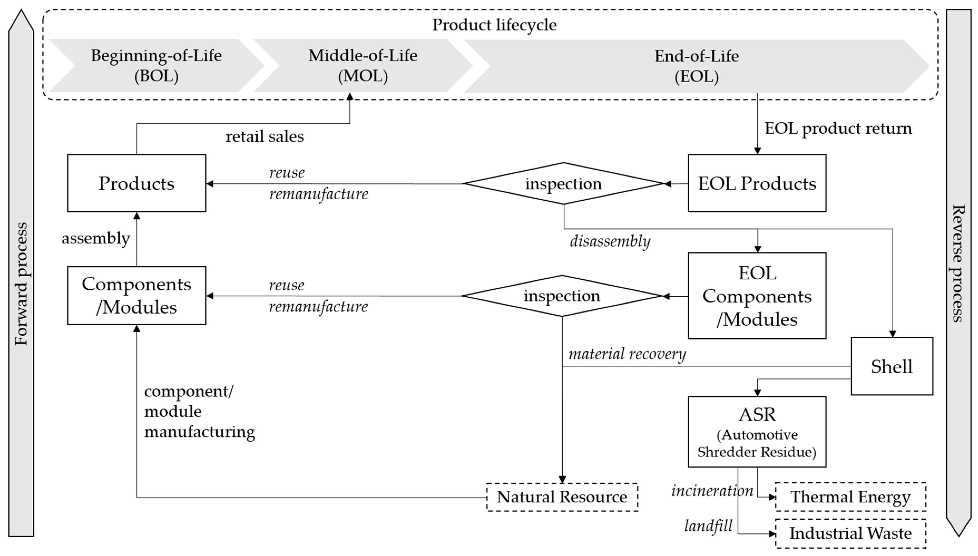
2.1. Product Lifecycle Management and Supply Chain Management
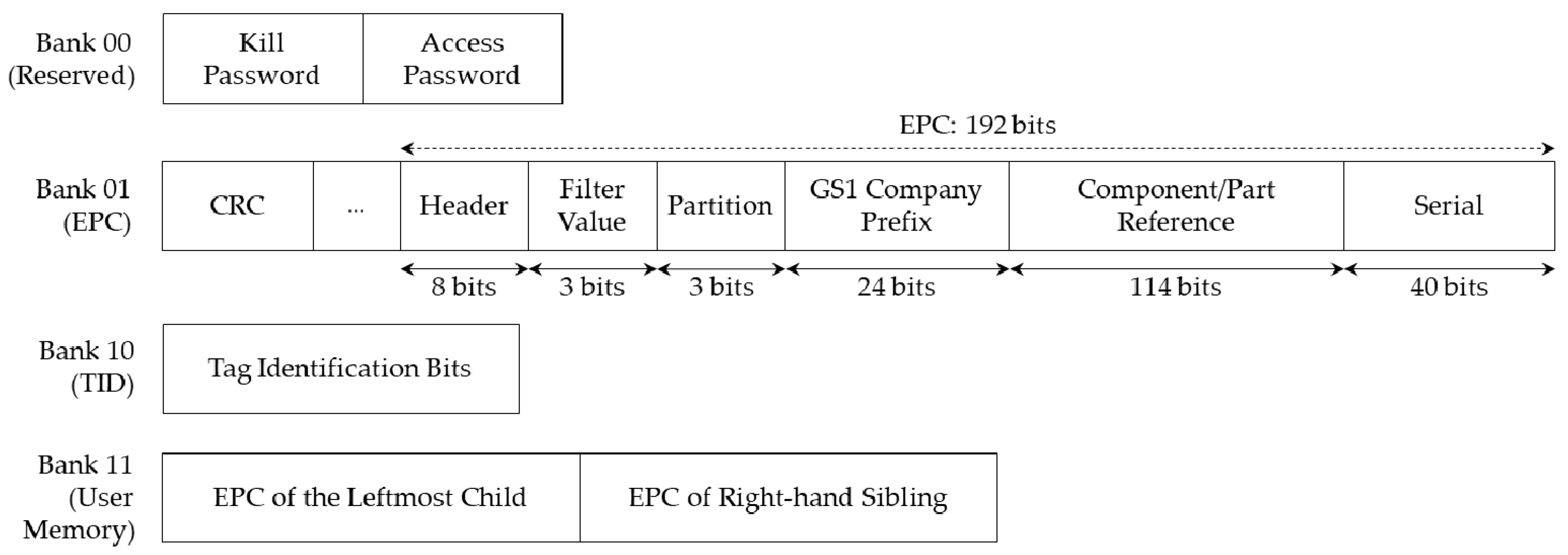
2.2. RFID and Gen2 Standards
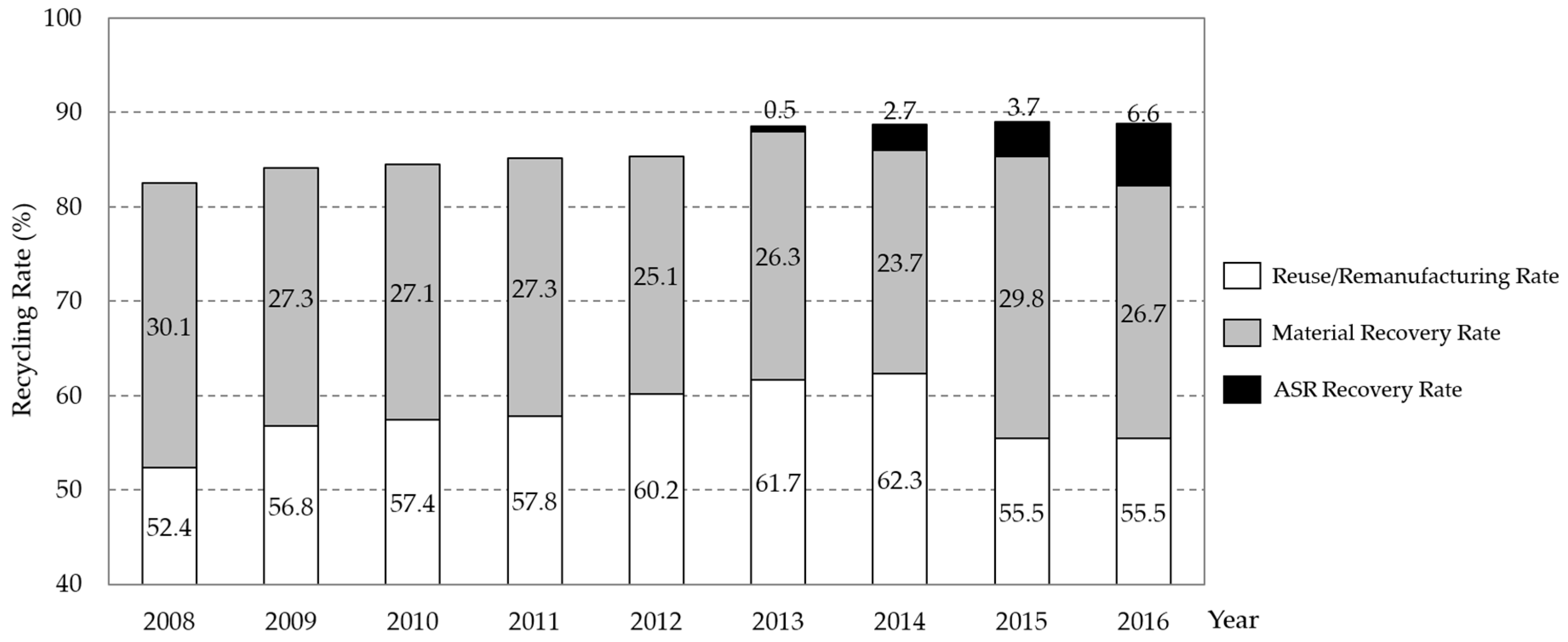
2.3. Illustrative Situation of Remanufacturing Industries
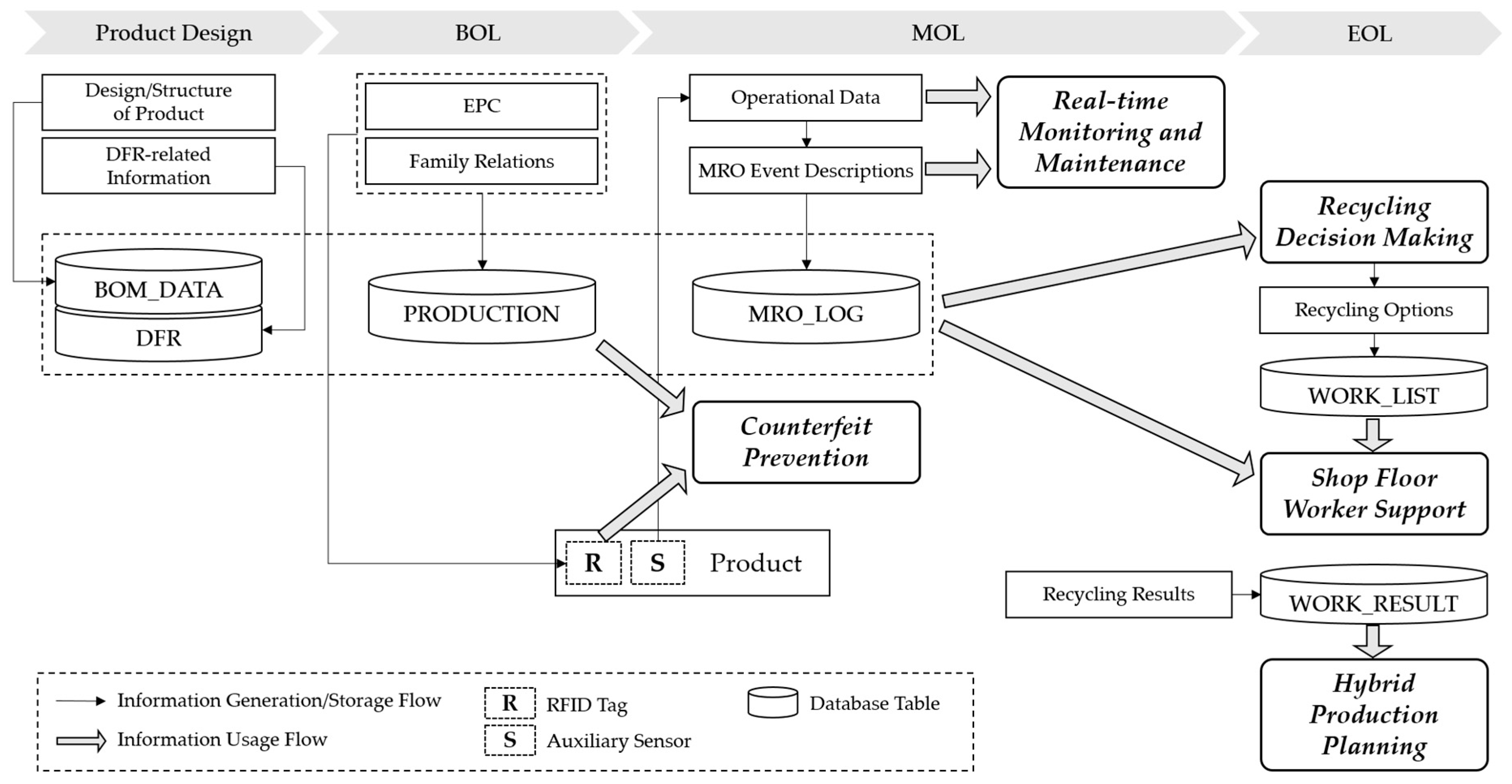
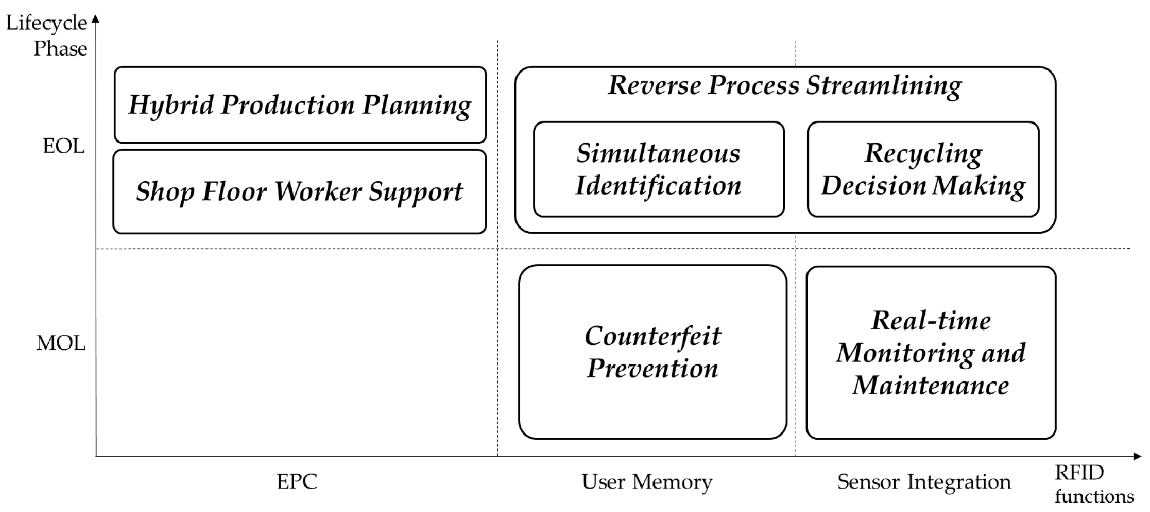
3. System Framework
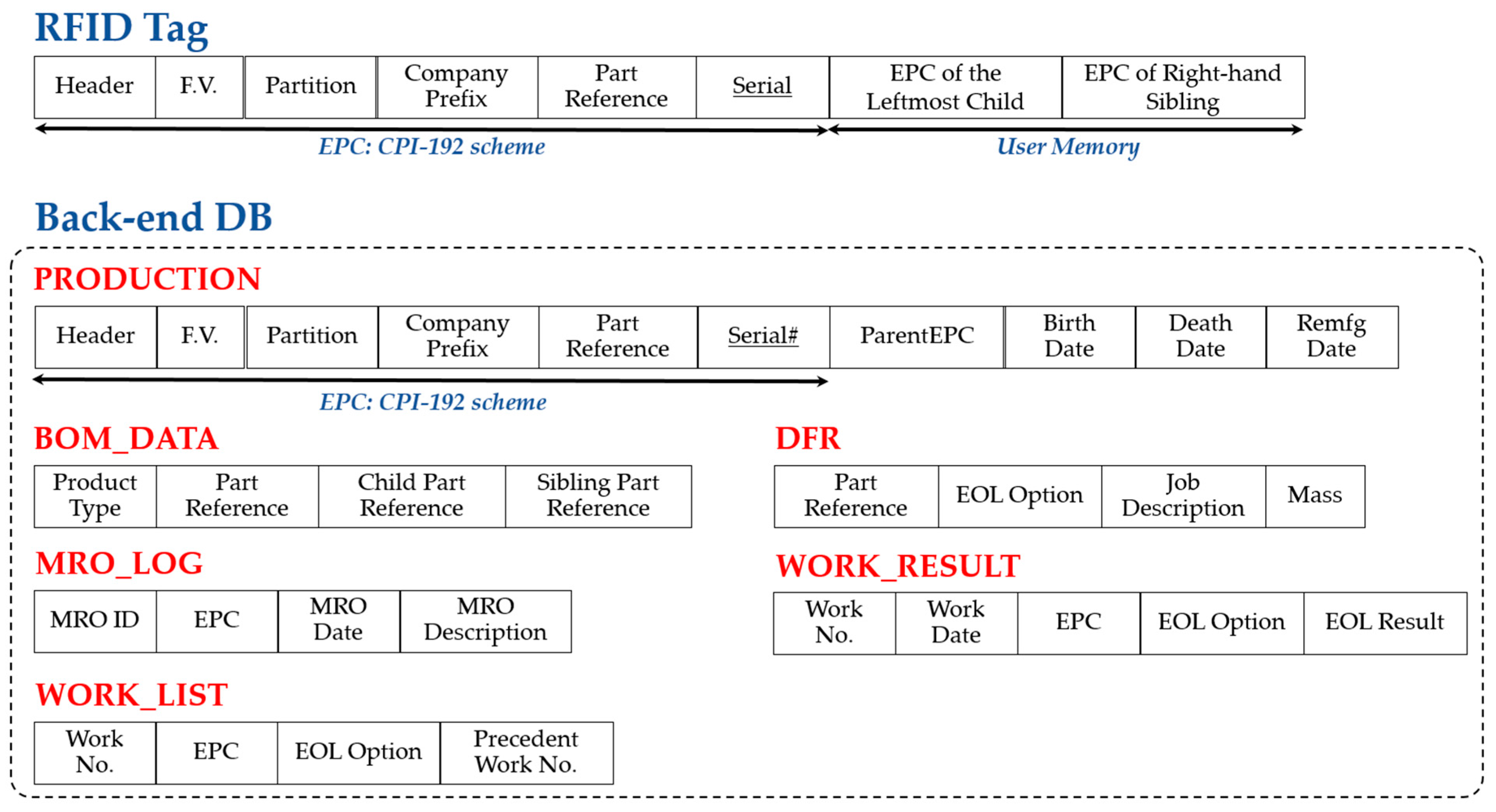
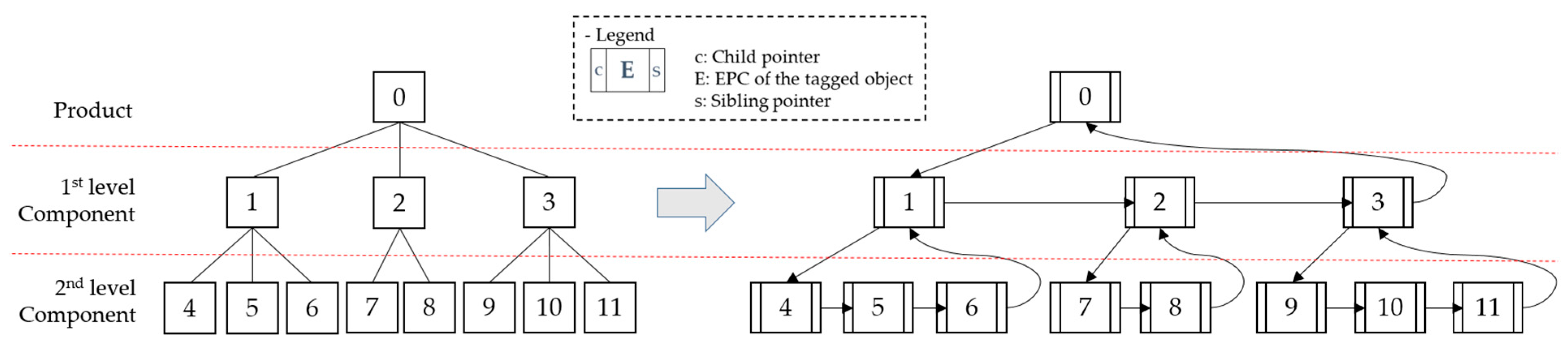
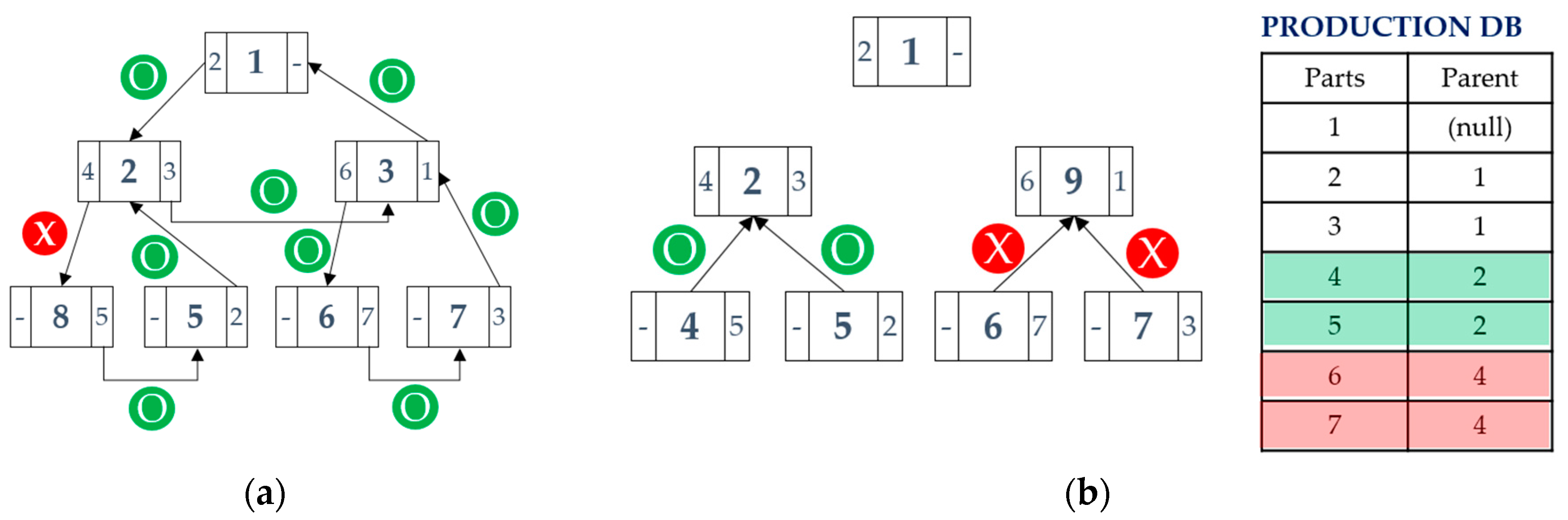
4. Data Architecture
- Include space in the memory for the maximum possible number of records;
- Store in separate records and indicate the location by pointer;
- Include space for partial storage in the memory, store overflowed records separately, and indicate them by pointer.
5. Application Scenario of the Proposed System
5.1. Counterfeit Prevention in the MOL Phase
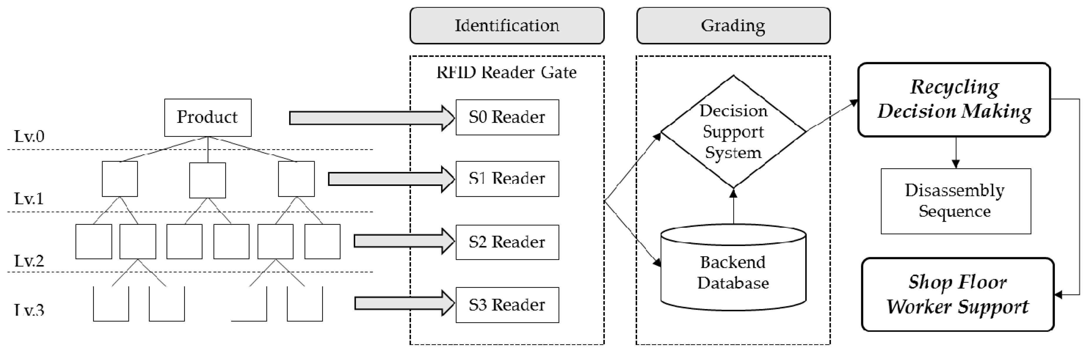
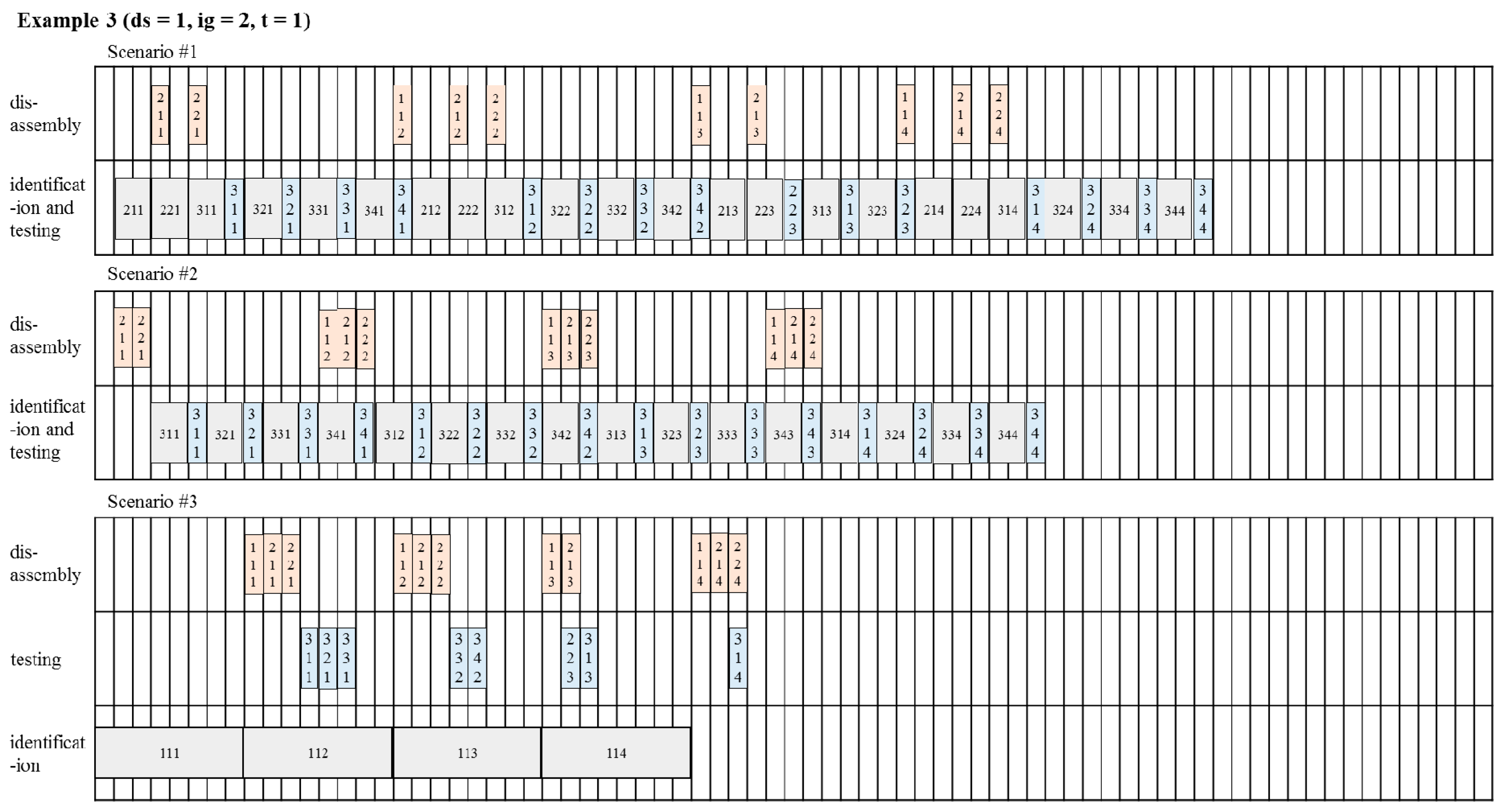
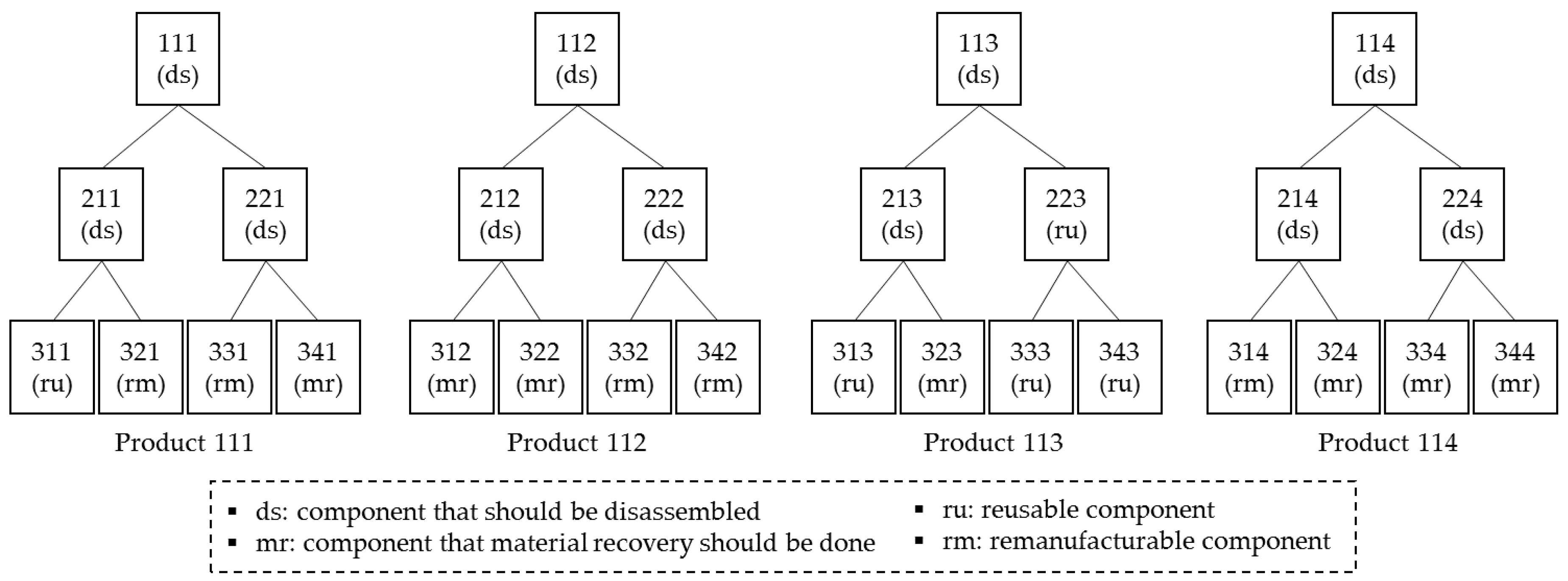
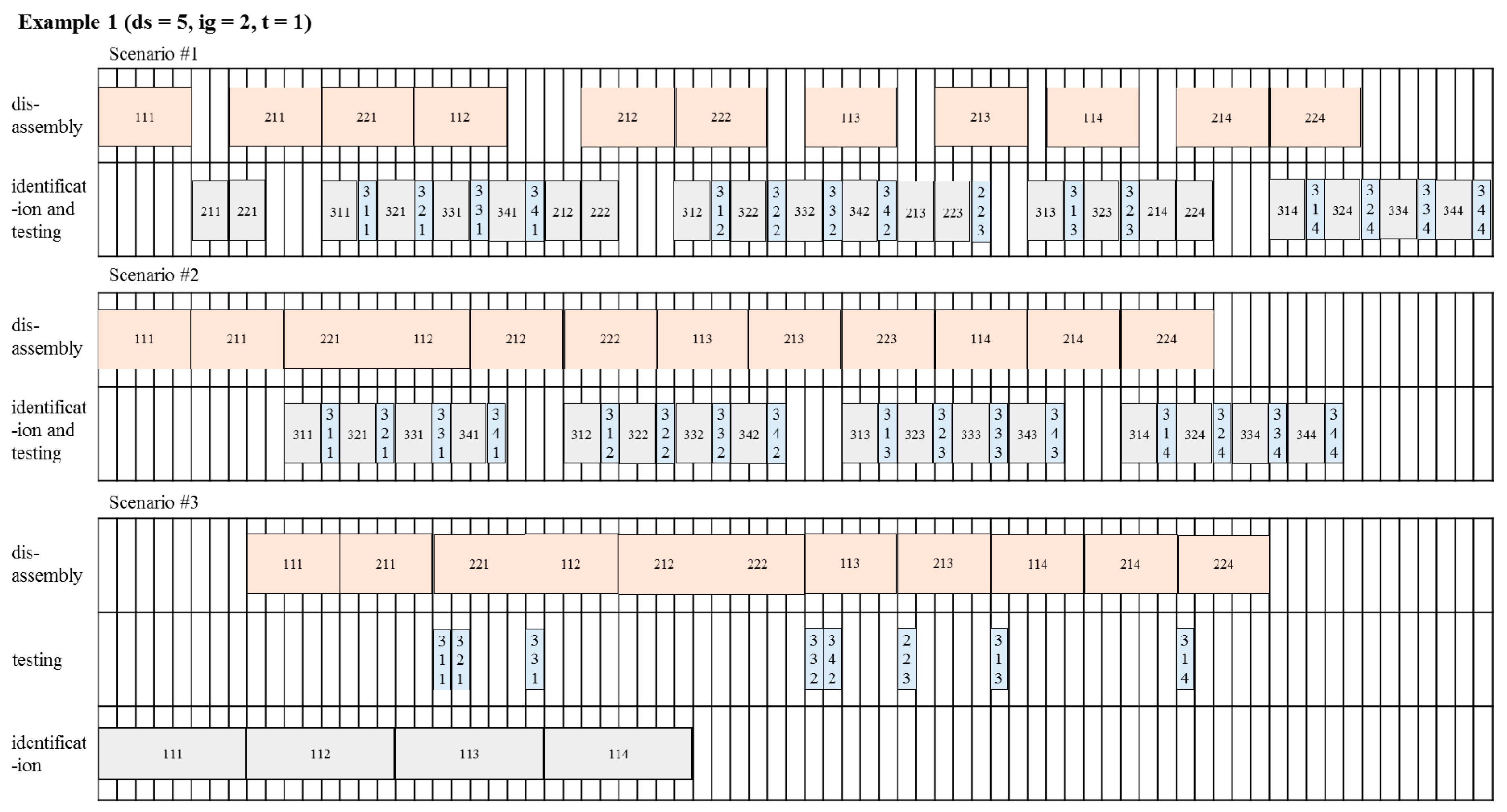
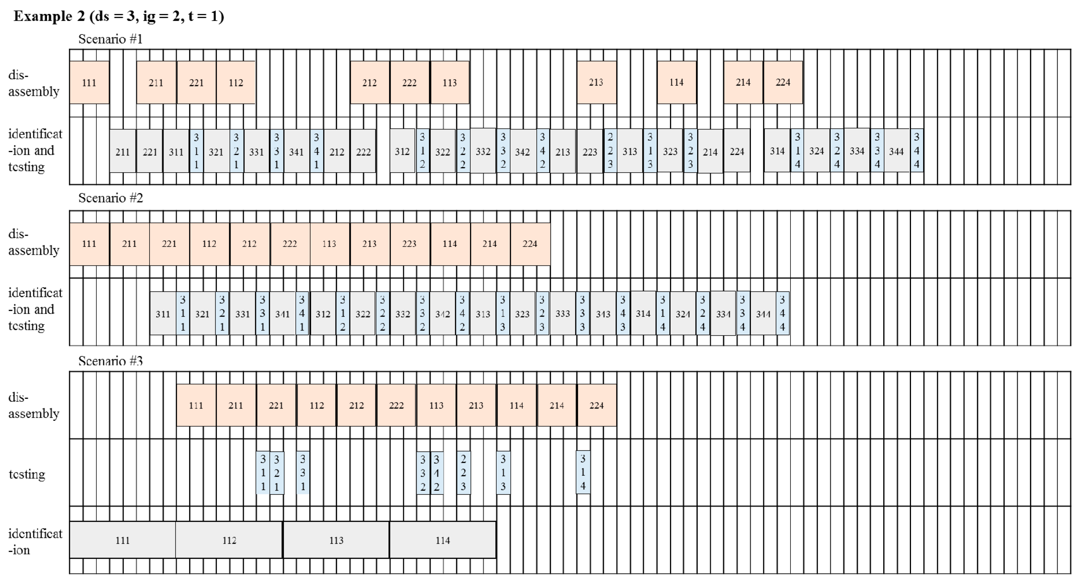
5.2. Reverse Process Streamlining
6. Conclusions
Acknowledgments
Author Contributions
Conflicts of Interest
References
- Seliger, G.; Kim, H.J.; Kernbaum, S.; Zettl, M. Approaches to sustainable manufacturing. Int. J. Sustain. Manuf. 2008, 1, 58–77. [Google Scholar] [CrossRef]
- Ober, J.A. Mineral Commodity Summaries 2017; US Geological Survey: Reston, VA, USA, 2017.
- Global Resources Stock Check. BBC Future, 18 June 2012.
- Krikke, H.; Bloemhof-Ruwaard, J.M.; Van Wassenhove, L.N. Design of Closed Loop Supply Chains: A Production and Return Network for Refrigerators; Erasmus Research Institute of Management (ERIM): Rotterdam, The Netherlands, 2001. [Google Scholar]
- Lifset, R.; Atasu, A.; Tojo, N. Extended producer responsibility: National, international, and practical perspectives. J. Ind. Ecol. 2013, 17, 162–166. [Google Scholar] [CrossRef]
- United States International Trade Commission. Remanufactured Goods: An Overview of the Us and Global Industries, Markets, and Trade; United States International Trade Commision: Washington, DC, USA, 2012; Volume 4356, pp. 332–525.
- Kerr, W.; Ryan, C. Eco-efficiency gains from remanufacturing: A case study of photocopier remanufacturing at Fuji Xerox Australia. J. Clean. Prod. 2001, 9, 75–81. [Google Scholar] [CrossRef]
- Kwak, M. Green Profit Design for Lifecycle. Ph.D. Thesis, University of Illinois at Urbana-Champaign, Champaign, IL, USA, 2012. [Google Scholar]
- Clottey, T.; Benton, W. Core Acquisitions Planning in the Automotive Parts Remanufacturing Industry; Ohio State University: Columbus, OH, USA, 2010. [Google Scholar]
- Lee, D.; Park, J. RFID-based traceability in the supply chain. Ind. Manag. Data Syst. 2008, 108, 713–725. [Google Scholar] [CrossRef]
- Gubbi, J.; Buyya, R.; Marusic, S.; Palaniswami, M. Internet of things (IoT): A vision, architectural elements, and future directions. Future Gener. Comput. Syst. 2013, 29, 1645–1660. [Google Scholar] [CrossRef]
- Tonelli, F.; Evans, S.; Taticchi, P. Industrial sustainability: Challenges, perspectives, actions. Int. J. Bus. Innov. Res. 2013, 7, 143–163. [Google Scholar] [CrossRef]
- Sudarsan, R.; Fenves, S.J.; Sriram, R.D.; Wang, F. A product information modeling framework for product lifecycle management. CAD Comput. Aided Des. 2005, 37, 1399–1411. [Google Scholar] [CrossRef]
- Parlikad, A.K.; McFarlane, D. RFID-based product information in end-of-life decision making. Control Eng. Pract. 2007, 15, 1348–1363. [Google Scholar] [CrossRef]
- Thomas, V.; Neckel, W.; Wagner, S. Information technology and product lifecycle management. In Proceedings of the 1999 7th IEEE International Symposium on Electronics and the Environment (ISEE-1999), Danvers, MA, USA, 13 May 1999; pp. 54–57. [Google Scholar]
- Tibben-Lembke, R.S.; Rogers, D.S. Differences between forward and reverse logistics in a retail environment. Supply Chain Manag. 2002, 7, 271–282. [Google Scholar] [CrossRef]
- Chandrasegaran, S.K.; Ramani, K.; Sriram, R.D.; Horváth, I.; Bernard, A.; Harik, R.F.; Gao, W. The evolution, challenges, and future of knowledge representation in product design systems. CAD Comput. Aided Des. 2013, 45, 204–228. [Google Scholar] [CrossRef]
- Denno, P.; Thurman, T. Requirements on information technology for product lifecycle management. Int. J. Prod. Dev. 2005, 2, 109–122. [Google Scholar] [CrossRef]
- Kiritsis, D.; Bufardi, A.; Xirouchakis, P. Research issues on product lifecycle management and information tracking using smart embedded systems. Adv. Eng. Inf. 2003, 17, 189–202. [Google Scholar] [CrossRef]
- Kiritsis, D. Closed-loop PLM for intelligent products in the era of the internet of things. CAD Comput. Aided Des. 2011, 43, 479–501. [Google Scholar] [CrossRef]
- Yang, X.; Moore, P.R.; Wong, C.; Pu, J.; Chong, S.K. Product lifecycle information acquisition and management for consumer products. Ind. Manag. Data Syst. 2007, 107, 936–953. [Google Scholar] [CrossRef]
- Främling, K.; Harrison, M.; Brusey, J.; Petrow, J. Requirements on unique identifiers for managing product lifecycle information: Comparison of alternative approaches. Int. J. Comput. Integr. Manuf. 2007, 20, 715–726. [Google Scholar] [CrossRef]
- Jun, H.B.; Shin, J.H.; Kim, Y.S.; Kiritsis, D.; Xirouchakis, P. A framework for RFID applications in product lifecycle management. Int. J. Comput. Integr. Manuf. 2009, 22, 595–615. [Google Scholar] [CrossRef]
- Cao, H.; Folan, P.; Mascolo, J.; Browne, J. RFID in product lifecycle management: A case in the automotive industry. Int. J. Comput. Integr. Manuf. 2009, 22, 616–637. [Google Scholar] [CrossRef]
- Kubler, S.; Derigent, W.; Främling, K.; Thomas, A.; Rondeau, É. Enhanced product lifecycle information management using “communicating materials”. CAD Comput. Aided Des. 2015, 59, 192–200. [Google Scholar] [CrossRef]
- Scheidt, L.-G.; Zong, S. Approach to achieve reusability of electronic modules. In Proceedings of the 1994 IEEE International Symposium on Electronics & the Environment, San Francisco, CA, USA, 2–4 May 1994; pp. 331–336. [Google Scholar]
- Meyer, G.G.; Främling, K.; Holmström, J. Intelligent products: A survey. Comput. Ind. 2009, 60, 137–148. [Google Scholar] [CrossRef]
- Klausner, M.; Grimm, W.M.; Hendrickson, C.; Horvath, A. Sensor-based data recording of use conditions for product takeback. In Proceedings of the 1998 IEEE International Symposium on Electronics and the Environment (ISEE 1998), Oak Brook, IL, USA, 4–6 May 1998; pp. 138–143. [Google Scholar]
- Li, J.; Tao, F.; Cheng, Y.; Zhao, L. Big data in product lifecycle management. Int. J. Adv. Manuf. Technol. 2015, 81, 667–684. [Google Scholar] [CrossRef]
- Simon, M.; Bee, G.; Moore, P.; Pu, J.S.; Xie, C. Modelling of the life cycle of products with data acquisition features. Comput. Ind. 2001, 45, 111–122. [Google Scholar] [CrossRef]
- Ilgin, M.A.; Gupta, S.M. Performance improvement potential of sensor embedded products in environmental supply chains. Resour. Conserv. Recycl. 2011, 55, 580–592. [Google Scholar] [CrossRef]
- Lu, Z.; Cao, H.; Folan, P.; Potter, D.; Browne, J. RFID-based information management in the automotive plastic recycling industry. In Proceedings of the 3rd International ICSC Symposium on Information Technologies in Environmental Engineering (ITEE 2007), Oldenburg, Germany, 29–30 March 2007; Kluwer Academic Publishers: Oldenburg, Germany, 2007; pp. 397–408. [Google Scholar]
- Saar, S.; Stutz, M.; Thomas, V.M. Towards intelligent recycling: A proposal to link bar codes to recycling information. Resour. Conserv. Recycl. 2004, 41, 15–22. [Google Scholar] [CrossRef]
- Luttropp, C.; Johansson, J. Improved recycling with life cycle information tagged to the product. J. Clean. Prod. 2010, 18, 346–354. [Google Scholar] [CrossRef]
- Wan, H.D.; Gonnuru, V.K. Disassembly planning and sequencing for end-of-life products with RFID enriched information. Rob. Comput. Integr. Manuf. 2013, 29, 112–118. [Google Scholar] [CrossRef]
- Kara, S.; Mazhar, M.; Kaebernick, H.; Ahmed, A. Determining the reuse potential of components based on life cycle data. CIRP Ann. Manuf. Technol. 2005, 54, 1–4. [Google Scholar] [CrossRef]
- Ondemir, O.; Ilgin, M.A.; Gupta, S.M. Optimal end-of-life management in closed-loop supply chains using RFID and sensors. IEEE Trans. Ind. Inf. 2012, 8, 719–728. [Google Scholar] [CrossRef]
- EPCglobal. EPC Radio-Frequency Identity Protocols Generation-2 UHF RFID; Specification for RFID Air Interface Protocol for Communications at 860 MHz–960 MHz; GS1 EPCglobal Inc.: Brussels, Belgium, 2013. [Google Scholar]
- Martin, H.; Millan, E.S.; Peris-Lopez, P.; Tapiador, J.E. Efficient ASIC implementation and analysis of two EPC-C1G2 RFID authentication protocols. IEEE Sens. J. 2013, 13, 3537–3547. [Google Scholar] [CrossRef]
- Korea Auto Dismantlement Recycling Association. Available online: http://www.kadra.or.kr (accessed on 13 May 2017).
- Pátkai, B.; McFarlane, D. RFID-Based Sensor Integration in Aerospace; Auto-ID Labs, University of Cambridge: Cambridge, UK, 2006; p. 1. [Google Scholar]
- EPCglobal. EPC Tag Data Standard 1.10; GS1 EPCglobal Inc.: Brussels, Belgium, 2017. [Google Scholar]
- Date, C.J. An Introduction to Database Systems; Addison-Wesley: Reading, MA, USA, 1990; Volume 1. [Google Scholar]
- Nam, K.; Chang, T.-W.; Park, J. Economic analysis on the implementation of automatic identification technologies in the end-of-life vehicle management process. Korean J. Logist. 2010, 18, 67–87. [Google Scholar]


| Recycling Options | Descriptions [8] | Cost/Resource Circulation Efficiency |
|---|---|---|
| Reuse | An item is used for its original purpose without repair | Better |
| Remanufacture | An item maintains its identity and structure and is restored as a like-new product | |
| Material Recovery | An item is disassembled, shredded, and/or separated to recover raw materials | |
| Disposal | An item is sent to disposal sites either for landfill or incineration | Worse |
| Scenario | SC1 | SC2 | SC3 | |||||||||
|---|---|---|---|---|---|---|---|---|---|---|---|---|
| Type of Process | ds 1 | ig 2 | t 3 | subtotal | ds | ig | t | subtotal | ds | ig | t | subtotal |
| Product 111 | 3 | 6 | 4 | 13 | 3 | 4 | 4 | 11 | 3 | 1 | 3 | 7 |
| Product 112 | 3 | 6 | 4 | 13 | 3 | 4 | 4 | 11 | 3 | 1 | 2 | 6 |
| Product 113 | 2 | 4 | 3 | 9 | 3 | 4 | 4 | 11 | 2 | 1 | 2 | 5 |
| Product 114 | 3 | 6 | 4 | 13 | 3 | 4 | 4 | 11 | 3 | 1 | 1 | 5 |
| Total | 11 | 22 | 15 | 48 | 12 | 16 | 16 | 44 | 11 | 4 | 8 | 23 |
| Processing Time | Performance Measures | ||||||
|---|---|---|---|---|---|---|---|
| ds 1 | ig 2 | t 3 | Scenario | Makespan | Total Idle Time | Idle Ratio | |
| Example 1 | 5 | 2 | 1 | SC1 | 75 | 36 | 0.240 |
| 5 | 2 | 1 | SC2 | 67 | 26 | 0.194 | |
| 5 | 8 | 1 | SC3 | 63 | 94 | 0.497 | |
| Example 2 | 3 | 2 | 1 | SC1 | 64 | 36 | 0.281 |
| 3 | 2 | 1 | SC2 | 54 | 24 | 0.222 | |
| 3 | 8 | 1 | SC3 | 41 | 49 | 0.398 | |
| Example 3 | 1 | 2 | 1 | SC1 | 60 | 50 | 0.417 |
| 1 | 2 | 1 | SC2 | 51 | 42 | 0.412 | |
| 1 | 8 | 1 | SC3 | 35 | 54 | 0.514 | |
© 2017 by the authors. Licensee MDPI, Basel, Switzerland. This article is an open access article distributed under the terms and conditions of the Creative Commons Attribution (CC BY) license (http://creativecommons.org/licenses/by/4.0/).
Share and Cite
Kim, Y.-w.; Chang, T.-W.; Park, J. Gen2 RFID-Based System Framework for Resource Circulation in Closed-Loop Supply Chains. Sustainability 2017, 9, 1995. https://doi.org/10.3390/su9111995
Kim Y-w, Chang T-W, Park J. Gen2 RFID-Based System Framework for Resource Circulation in Closed-Loop Supply Chains. Sustainability. 2017; 9(11):1995. https://doi.org/10.3390/su9111995
Chicago/Turabian StyleKim, Young-woo, Tai-Woo Chang, and Jinwoo Park. 2017. "Gen2 RFID-Based System Framework for Resource Circulation in Closed-Loop Supply Chains" Sustainability 9, no. 11: 1995. https://doi.org/10.3390/su9111995
APA StyleKim, Y.-w., Chang, T.-W., & Park, J. (2017). Gen2 RFID-Based System Framework for Resource Circulation in Closed-Loop Supply Chains. Sustainability, 9(11), 1995. https://doi.org/10.3390/su9111995