Article

Macro Micro Studio: A Prototype Energy Autonomous Laboratory

1
Architecture and Planning, School of Social Sciences, University of Dundee, Nethergate, Dundee DD14HN, UK
2
Engineering, School of Science and Engineering, University of Dundee, Nethergate, Dundee DD14HN, UK
3
Physics, School of Science and Engineering, University of Dundee, Nethergate, Dundee DD14HN, UK
*
Author to whom correspondence should be addressed.
These authors contributed equally to this work.
Sustainability 2016, 8(6), 500; https://doi.org/10.3390/su8060500
Submission received: 20 January 2016 / Revised: 9 May 2016 / Accepted: 16 May 2016 / Published: 25 May 2016

Abstract

:
In 2011, the Departments of Architecture, Physics and Engineering began the development of a small Passivhaus standard, renewable energy self-sufficient studio at the University Botanical Gardens in Dundee. The prototype was conceived as an experimental, integrated technical platform to monitor the performance of an ultra-low-energy consumption, energy positive building in the Scottish climate, and understand user behaviour in relation to managing energy in-use and reducing occupant’s energy consumption. The building fabric has been constructed using regional sustainable materials, including a low-thermal bridging timber kit relying on Scottish small cross-section timber and a novel foam concrete (air entrained) slab foundation. While further work is required to complete the installation of the renewable energy system, predictive modelling indicates that energy autonomy can be largely achieved. With the recent introduction of the new Passivhaus 2009 criteria in October 2015, this project provides an insight into the practical application of an autarkic energy system in a northern European climate. The following paper describes the research rationale, the processes and decision making in the development of the formal and technical design of the building and discusses our current thinking in the design and quantification of the energy system.

1. Low Energy, Net Zero and Energy Positive Buildings

In the European Union (EU), energy used in buildings accounts for approximately 40% of the EU’s final energy consumption and 36% of CO2 emissions, making the building sector the largest energy consuming and climate change inducing sector [1]. In Northern climates, where heating demand dominates, it has been shown that fabric efficiency improvements (FEES) are the most cost effective means for improving the energy efficiency of buildings. Currently, Passivhaus (PH) sets the benchmark standard for achieving ultra-low energy performing buildings and has been a significant step beyond current UK legislation in terms of reducing Specific Space Heat Demand (SSHD). Although FEES and passive building design strategies have an important role to play in CO2 reduction, they can only go part way to reducing regulated energy demands. While space and water heating account for nearly half of total end use emissions, unregulated demand for electricity, driven by increased plug load, is growing faster than any other final energy source [2]. Reducing demand for both regulated primary energy and unregulated energy use within buildings will become increasingly important as the national grid is decarbonized and the inherent constraints on renewable power generation become more onerous [3]. Consequently, buildings are likely to play a more significant strategic role in their relationship and contribution to the national energy mix and managing energy consumption behaviour. In order to incentivise a reduction in CO2 emissions, the European Parliament passed the European Directive 2002/91/EC., [4], recast in 2010 as 2010/31/EU [5] on the Energy Performance of Buildings (EPBD) requiring a common methodology for calculating the integrated energy performance of buildings. This legislation requires all new buildings to be nearly zero-energy by the end of 2020 and all new public buildings must be nearly zero-energy by 2018. In 2013, a European Commission progress report COM(2013)483 [6], found that EU countries had to significantly step up their efforts to take more strategic advantage of the opportunities presented by nearly zero energy buildings (NZEB) [7].
In recent years a number of building concepts have emerged which claim to achieve “net-zero energy” (nZEB), “zero energy” (ZEB) or “energy positive” performance standards. These usually describe buildings that use the power or heat grid to balance over time energy supply, demand and export. These concepts use metrics based on energy, carbon and energy cost to achieve a net energy or carbon balance of zero or positive, i.e., efficiency gains have been made such that the balance of energy needs can be supplied with renewable energy technologies and any excess energy can be exported off-site. Musall and Voss discuss various national standards in Europe for achieving energy balancing in buildings including the Swiss MINERGIE-A, the now obsolete Code for Sustainable Homes, UK and zeroHAUS certificate, Germany which is based on the Swiss concept of the 2000 Watt Society [8]. They identify discrepancies and lack of comparability between different balancing concepts due to the use of different indicators such as cost, energy, balance limits, balance periods and types of balance. Marszal and Heiselberg conducted a literature review of existing definitions of nZEBs, identifying four principle classifications: “Net-Zero Site Energy”, “Net-Zero Source Energy”, “Net-Zero Energy Costs” and “Net-Zero Energy Emissions” [9]. They raise a number of issues including questioning the unit of balance (final/delivered energy; primary energy; exergy; energy costs or CO2 emissions) recommending that primary energy is considered as this is the best expression of the actual building energy use. They also question the type of energy used in calculating the balance (operational energy; embodied energy and/or unregulated energy), inclusion of building energy efficiency in the calculation and the quality of the Low and Zero Carbon Generating Technologies (LZCGT’s) used. Similarly, Kibbert and Fard discuss definitions for low energy and ZEBs, identifying a wide range of strategies, non-standard definitions and confusions between different fundamental concepts, e.g., “net-zero energy”, “carbon-neutral” and “low-energy building” and call for standard definitions of these concepts [10]. They make specific recommendations to focus on carbon neutrality as a metric which reflects the quality of the energy source and to define a new concept for “net-zero low-energy buildings” which incentivizes energy conservation and potentially lowers the cost of implementing LZCGTs due to the reduced demand. They also recommend that energy is metered at the building site for the energy balance. Hernandez expands the scope of ZEBs from considering not only primary energy used in the building over its lifetime to Lifecycle-Zero Energy Buildings LC-ZEBs, which include, in addition, consideration of the energy embodied in a buildings construction and technical systems to be equal to or less than the energy generated by the renewable systems within the building over its lifetime [11].
Pless and Torcellini propose a hierarchical classification system for ZEBs based on the location and type of renewable sources used [12]. The classification scale ranges from nZEB:A to nZEB:D and is weighted to LZCGTs that are available within the building footprint at the site and a fabric 1st approach to energy conservation is incentivised. They also recognize that off-grid nZEBs are difficult to achieve due to the limited energy storage options available which means that the electrical generation systems are often oversized for winter demands meaning excess energy produced in the summer cannot be exported or effectively used on-site. Peacock discusses balancing energy supply and demand with storage and controls in micro-grid scale autarkic energy systems [13]. They describe the principles of typical autarkic energy systems as comprising a micro-grid, well understood energy supply and demand characteristics, opportunities for energy storage of various types and controls able to manage the harmonization of system components and users capable of working within the constraints of autarkic systems, i.e., reduced energy availability and intermittency issues [14]. Miller calls for greater integration and scaling of grid-energy storage highlighting this to be a major barrier to building further capacity for LZCGTs in the UK [15]. It is identified that management of energy flows between buildings and grid and reducing demand side energy requirements will be critical issues to address in the future to meet the trilemma of achieving affordability and reliability while decarbonizing.
As countries make further progress towards decarbonizing their energy infrastructure, it is clear that buildings will need to play a more significant role in both supplying the grid with renewable energy but also in contributing to balancing demand, generation and intermittency issues. Since 1991, Passivhaus has defined the benchmark standard for ultra-low energy efficient buildings by taking account of regional climate, aspect, altitude, airtightness and FEES in the calculation methodology. With the recent introduction of PHPP 2009, in 2015, the Passive House Classic, Plus and Premium classes certify for Primary Energy Renewable (PER) to account for renewable electricity generated from solar, wind and hydro (Figure 1). These aspirational sustainability standards recognize that energy storage is necessary for transferring surplus energy to time periods with lower energy gains accounting for short-term and seasonal storage solutions and provides a means for calculating a net zero energy balance (Figure 1).
The new PH criteria simulate hourly resolution load profiles of the energy demand where the energy is supplied solely by renewable energy (RE) sources, including all necessary storage facilities such that:
P E R =   E n e r g y   s u p p l y   f r o m   r e n e w a b l e   s o u r c e s F i n a l   e n e r g y   d e m a n d   a t   t h e   b u i l d i n g
In the Passivhaus Planning Package (PHPP) 2009, the resulting PER factors describe how much more renewable energy must be supplied in order to cover the final energy consumed at the building, including all losses incurred along the way [16,17]. This recognizes that short-term storage is more efficient than seasonal storage due to the high losses of the latter and the potential oversizing of the generation system to account for this. The following paper describes the design concepts, technical specifications and predicted performance of an ultra-low-energy autarkic building prototype. Conceived as an integrated experimental laboratory, it tests Passivhaus building energy efficiency in the Scottish climate and an autarkic renewable energy system relying on a 3 kW VAWT, 4.8 kW PV array and 24 kWh Lithium Ion battery providing 1.5 days of short-term storage capacity. The predicted performance of the system is discussed in relation to the new Passivhaus 2009 criteria (Figure 2).

2. Research Framework

2.1. Project Background

It is widely recognized that building energy performance in the UK has been lagging behind leading energy standards in some European countries such as Scandinavia, Germany and Switzerland. Several factors have impacted on this including poorer FEES, lower airtightness standards and negation of regional climate in the calculation of the space heat demand of buildings. At the beginning of the research, there were over 37,000 Passivhaus houses certified in Europe, but only a few Passivhaus houses had been constructed in Scotland, of which two of these were being environmentally monitored. Furthermore, there were few, if any, built examples of net-zero low-energy buildings and there has been little evidence of energy storage (heat or electricity) being applied in practice at any significant scale. The Sullivan Report, first introduced in 2007 [18], enforced through the Scottish Building Standards defined incremental targets for CO2 emission reduction from new buildings, with the latest regulation amendment coming into force on 1 October 2015. Compliance under Section 6 Energy is now impossible without some form of renewable energy generation.
The research described in this paper, which began in 2011, tests in practice solutions for energy balancing in an energy autarkic building prototype using the 2007 Passivhaus criteria to benchmark building energy use while addressing unregulated demand through integrated renewable energy generation and storage to achieve self-sufficiency. However, while energy has been a principle focus, the research has adopted a holistic approach to the development of a sustainable building considering total energy in-use reduction, low-embodied energy, water conservation and the building’s formal response to these issues and its context. All data supporting this study are provided as supplementary technical information accompanying this paper and are openly available from the University of Dundee Institutional Repository Discovery at http://doi.org/10.15132/10000117.

2.2. Innovative Renewable Energy Building Prototype Research

Innovative low and zero-energy building prototypes developed to test the efficacy of renewable energy concepts in buildings have a long history. The MIT Solar Houses built between 1939 and 1959 investigated passive and active solar generation and thermal storage technologies to achieve self-sufficiency in heat and hot water demand, providing the first scientifically benchmarked approaches to solar housing [19]. The Vagn Korsgaard Zero Energy Home in Denmark in 1977 and the Saskatchewan Conservation House in 1979 proposed buildings that had a close to zero annual heating need that was achieved through very high fabric specifications and the use of MVHR without the need for active thermal storage [20]. These were forerunners to the Passivhaus concept which developed the economic and technical viability for upscaling these principles. The Velfac “Active House” designed in 2009, went beyond zero emissions producing more energy than the building used in its operation with export energy allowing payback of the build energy costs within 30 years [21]. Other similar concepts exist across Europe including the “Med in Italy” prototype designed for the Solar Decathlon and “LivingBox”, developed for the Milan MADE Expo by Trento University [22]. The Creative Energy Homes Project (CEH) constructed on the University Park Campus, Nottingham, contains seven state-of-the-art low energy houses, designed to various energy performance standards between 2001 and 2014 that are connected to a residential hydrogen-based micro-grid providing mid-term storage of renewable energy generation to achieve self-sufficiency [23]. The Honda Smart Home US, a recent collaboration between Honda and Berkeley University combines a range of energy saving concepts such as adaptive lighting, water management, passive design, active heating and cooling and low embodied energy construction [24] The NZEB grid connected system uses a Home Energy Management System to manage electrical energy generation from the PV rooftop array and 10 kWh Lithium Ion battery storage with grid import and export capability. MagicBox, a self-sufficient solar house at the Institute of Solar Research, Madrid is equipped with grid connected PV generation, lead-acid batteries, controllable appliances and smart metering. It tests the principles of Active Demand Side Management (ADSM); the automatic control of household demand combined with renewable energy generation and automatic control of the grid interface to maximize self-consumption of energy [25]. Modelling simulations were carried out which showed that ADSM reduces the use of the storage systems and therefore reduces the losses with regard to the storage system efficiency. The Macro Micro Studio builds on the principles established in the more recent examples and is designed to test an autarkic solution located at 56.4° North in a Scottish maritime climate.

2.3. Aims and Objectives

During the four years of developing the project, the research aims were re-evaluated and refined as the context and design requirements became better understood, namely:
  • to understand the efficacy of designing a grid-tied, net-zero low-energy building that integrates carbon negative LZCGTs, medium-scale power storage, energy management and predictive controls;
  • to monitor physical and environmental performance of a Passivhaus standard building and understand user behaviour in relation to predictive weather data and energy consumption;
  • to develop a formal, spatial and technical language for a net-zero low-energy building that responds to the high-value landscape context of the University Botanic Gardens.
A number of specific objectives were identified:
  • to provide an integrated technical platform and a unique opportunity to develop and study the efficacy of the interfaces between the building, a local decentralised micro-grid, and the user enabling these more complex systems to be understood and managed;
  • to develop smart bottom-up systems thinking for buildings that is driven by needs for warmth, cooling, power and convenience;
  • to develop a low-embodied carbon construction system using as far as possible regional resources, technologies and skills and to implement new technologies where appropriate to demonstrate potential for up-scaling;
  • to develop energy harvesting and storage incorporating medium-scale modular Li-ion battery technology within the building footprint to provide the opportunity for flexible management of storage, import and export of energy;
  • to integrate sensor technologies to provide understanding of the spatial aspects of user behaviour and capture data on the relationship between occupants, the building fabric (e.g., opening windows) and technical systems (hot water use, ventilation, plug demand, etc.);
  • to develop intelligent user controls for the building that provide feedback on system performance, allowing users to alter their energy consumption behaviour and/or control the building behaviour.
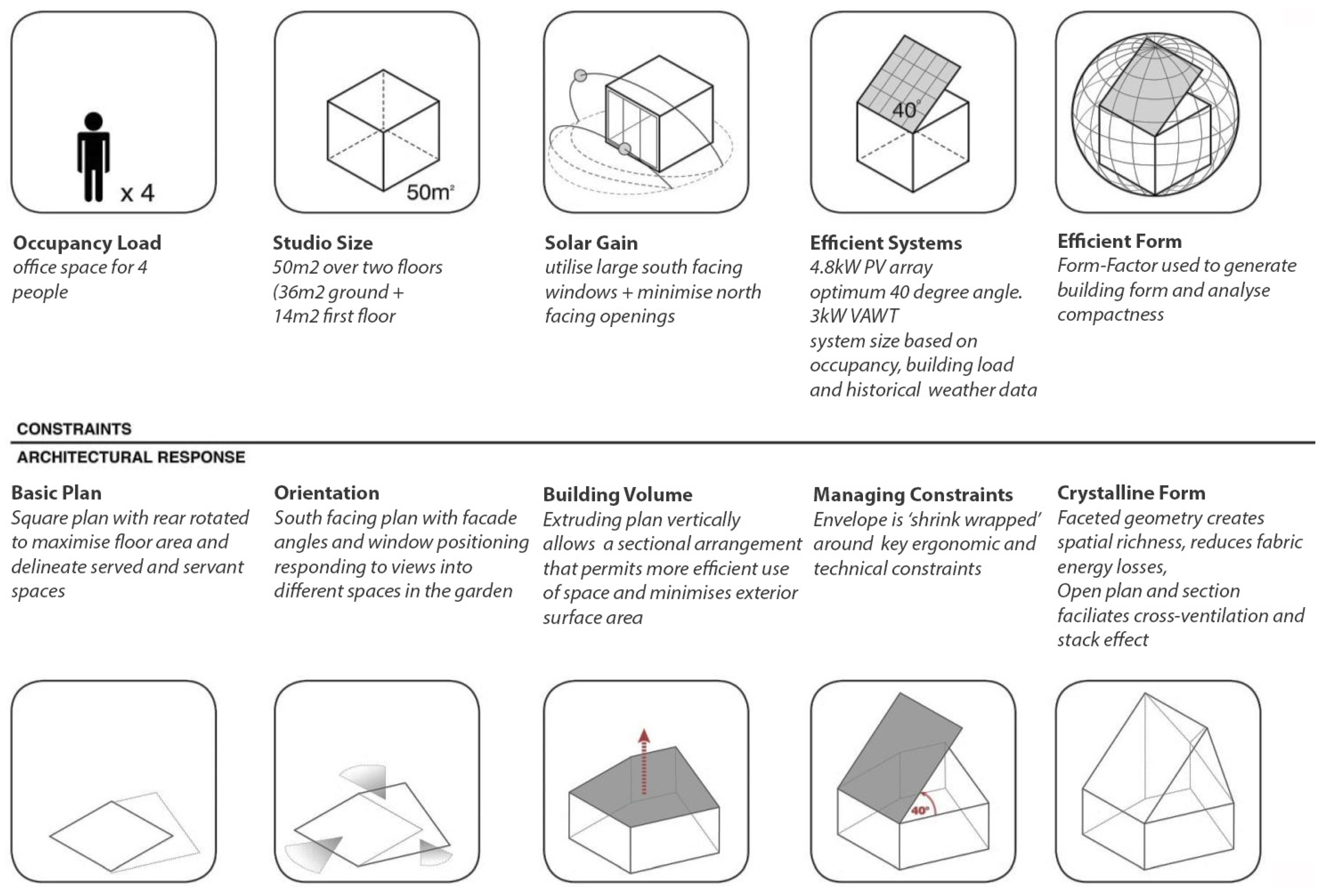
2.4. Design Brief

The project was driven by both the technical requirements for achieving net-zero energy and a qualitative agenda to challenge the language and formal character of “green buildings”. The brief was developed iteratively over the course of the project with the principle design considerations being summarized in Table 1.

3. Spatial and Environmental Design

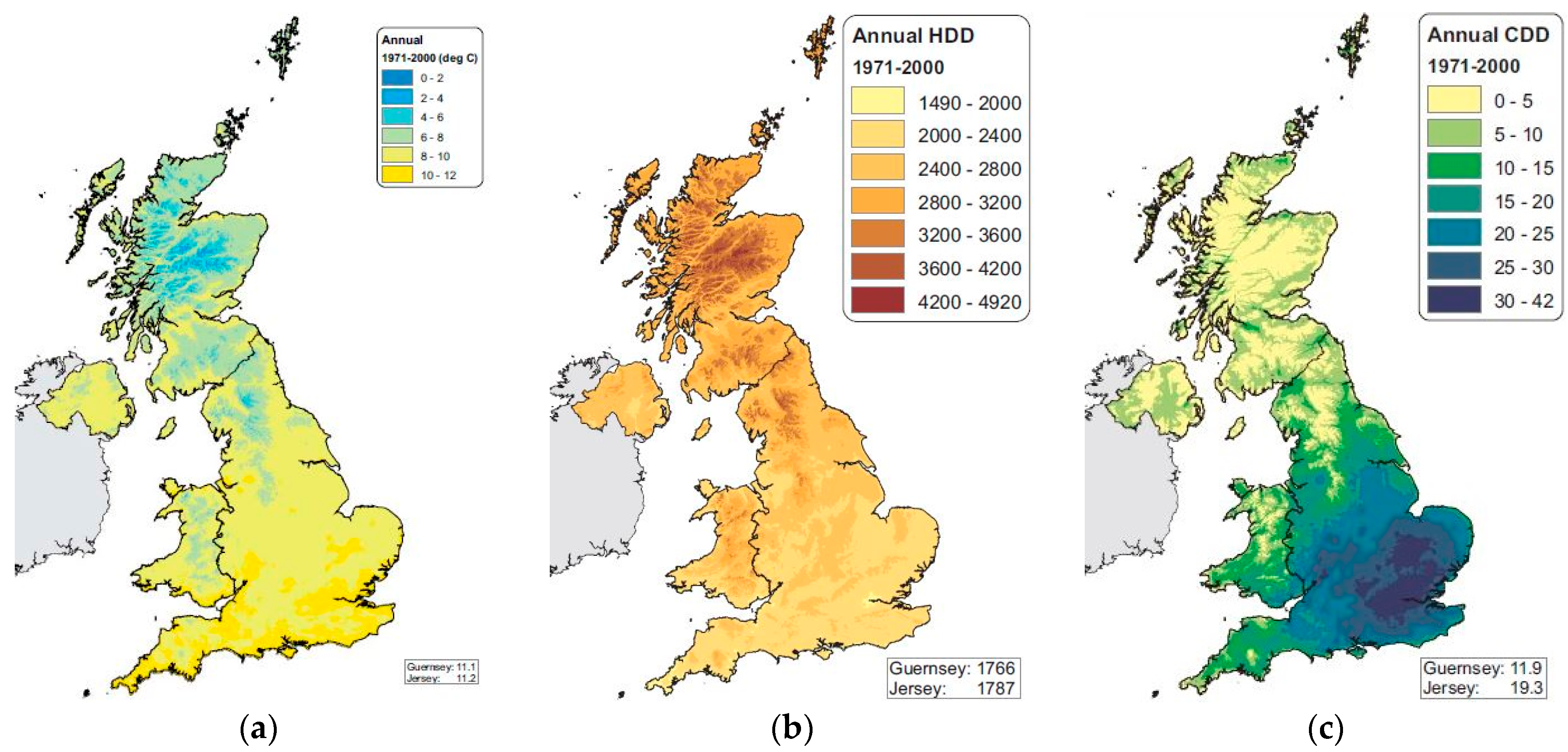
3.1. Environmental Conditions

While Scotland has a comparatively small land mass there are significant regional differences in climate due to its maritime influence, warm Gulf Stream affecting the west coast, a latitude range from 54.98°N to 60.38°N, complex, mountainous topography, very high average wind speeds and high rainfall. The climate is temperate, and compared to Labrador, Canada which lies at the same latitude, it is significantly warmer. The Building Research Establishment (BRE) produces nine climate data areas for Scotland, namely: North West England; SW Scotland; Borders; West Scotland; East Scotland; North East Scotland; Highlands; Western Isles; Orkney; Shetland [26]. This climate data gives a more accurate picture of regional differences in climate and is approved by the Passivhaus Institute for use in calculations in PHPP. The most influential climatic factors are the Solar Insolation (SI) totals (kWh/(m2a)) and the Heating Degree Hours per annum (Gt value) (Figure 3). These figures broadly represent the possible heat gains due to climate (SI) and the magnitude of the heat losses (Gt value). This data shows the most available total solar irradiation is available in the East of Scotland (1077 (kWh/(m2a)). December has the least sunshine, May/June are the sunniest months, with sunshine decreasing with distance from the coast, increasing altitude and latitude.

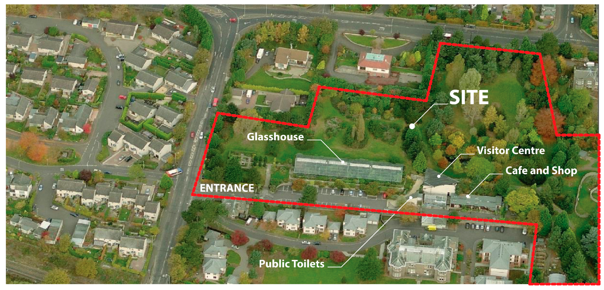
3.2. Site Constraints

The Studio is situated on a site to the west end of the Botanic Gardens, which lie in 9.5 hectares of heavily wooded, south facing, gently sloping land adjacent to the River Tay (Figure 4). The Garden contains a collection, organized by geographic origin, of indigenous plants from around the world. The purpose of the Garden is for research, education and leisure and receives more than 80,000 visitors a year making it an ideal location for a demonstration project [28]. The Studio is on the site of a former mature shelter belt and sits to the north between the main reception building and glasshouse. The site area is approximately 40 m in length by 10 m in width, rising by approximately a metre along its main axis running south to north. The building is located to the north of the site, to avoid services running in the ground at the south and to take advantage of the slope reducing any overshadowing from adjacent buildings and to maintain a 10 m fire separation from the glasshouse.

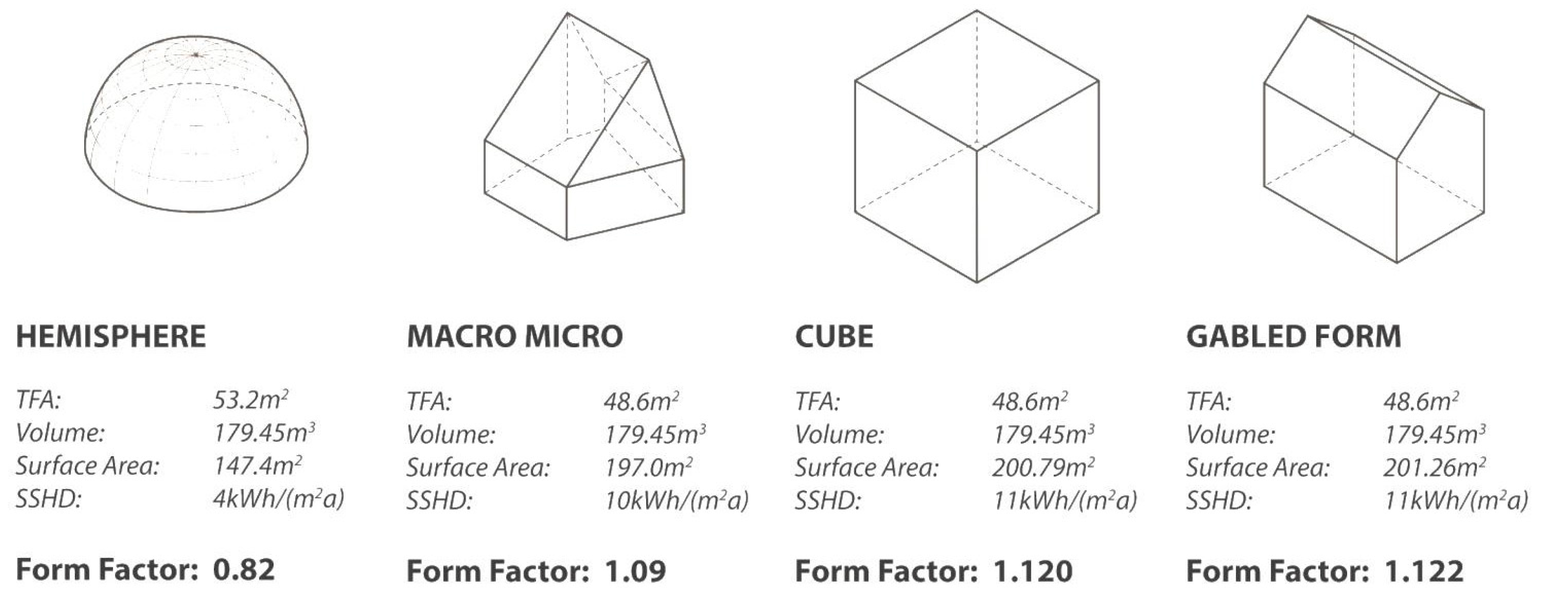
3.3. Energy Efficiency, Form Factor and Building Geometry

Generally, the main environmental design issue for buildings in Scotland is retaining heat in the winter, rather than cooling in the summer. Passivhaus designs can function well in either scenario, but to take advantage of passive solar gain in this climate, the building needs to be orientated with the majority of main glazed areas facing approximately south (± 35°) with a minimum of glazing to the north. However, in order to provide a suitable area of roof on which to install the PV, the roof needs to face due south with an optimum inclination of 40 degrees to the horizontal.

3.3.1. Form Factor Analysis

Consideration needed to be given to both the architectural aesthetic of the Studio and to its thermal form-factor: a ratio between the external surface area and the internal volume (SA:V). Form Factor defines a building’s compactness or density. The surface area relates to the building envelope and material required to construct it while the volume represents the internal space of the building based on its treated floor area and height. The ratio is inversely proportional to its size, as the object scale increases, the SA:V ratio decreases. Small buildings have a higher SA:V ratio than larger buildings with an identical form. Therefore, it is important that small detached buildings are designed with compact and simple forms, whereas more complex geometries can be accommodated more efficiently in larger buildings [29]. Similarly, buildings with the same orientation and FEES may have significantly different heating demands simply as a result of their Form Factor. In order to achieve the highest thermal efficiency, a smaller ratio is desired, minimising the heat loss through the building envelope. An analysis using PHPP 2007 compared the form factor and Specific Space Heating Demand of the studio with other generic solids of the same volume (Figure 5). The results emphasize the importance of solar gains, which generate around 70% of the energy required to offset heat losses with the most significant total heat losses occurring through opaque building elements such as walls and roof. The Studio produces less solar heat gain than the other forms due to the glazing orientation as the cranked footprint of the plan turns the orientation of some windows away from a directly south facing orientation. However, since the Macro Micro Studio’s geometry has less external surface area than the cube and gable forms it loses less heat through the external envelope. The hemisphere has the smallest surface area ratio, which means less heat is transmitted through the thermal envelope resulting in the lowest heating demand. However, this result should be treated with some caution, as there are limitations in PHPP which affect the ability to properly take account of glazing parameters in curved surfaces.
The resulting geometrical form of the Studio was derived from a cube, and through subtractive transformation achieves a more efficient Form Factor ratio, closer to that of a sphere but without the inherent constraints imposed by a spherical geometry. Initially this was tested through an iterative design process using scaled physical models. A number of rules were developed to determine the form based around the spatial organization by varying controlling factors in the plan geometry and sectional geometry (Figure 6). A parametric model of the geometry was developed in Grasshopper software in order to test the range of variations that could be produced and their effect on the physical, environmental and aesthetic outcomes.

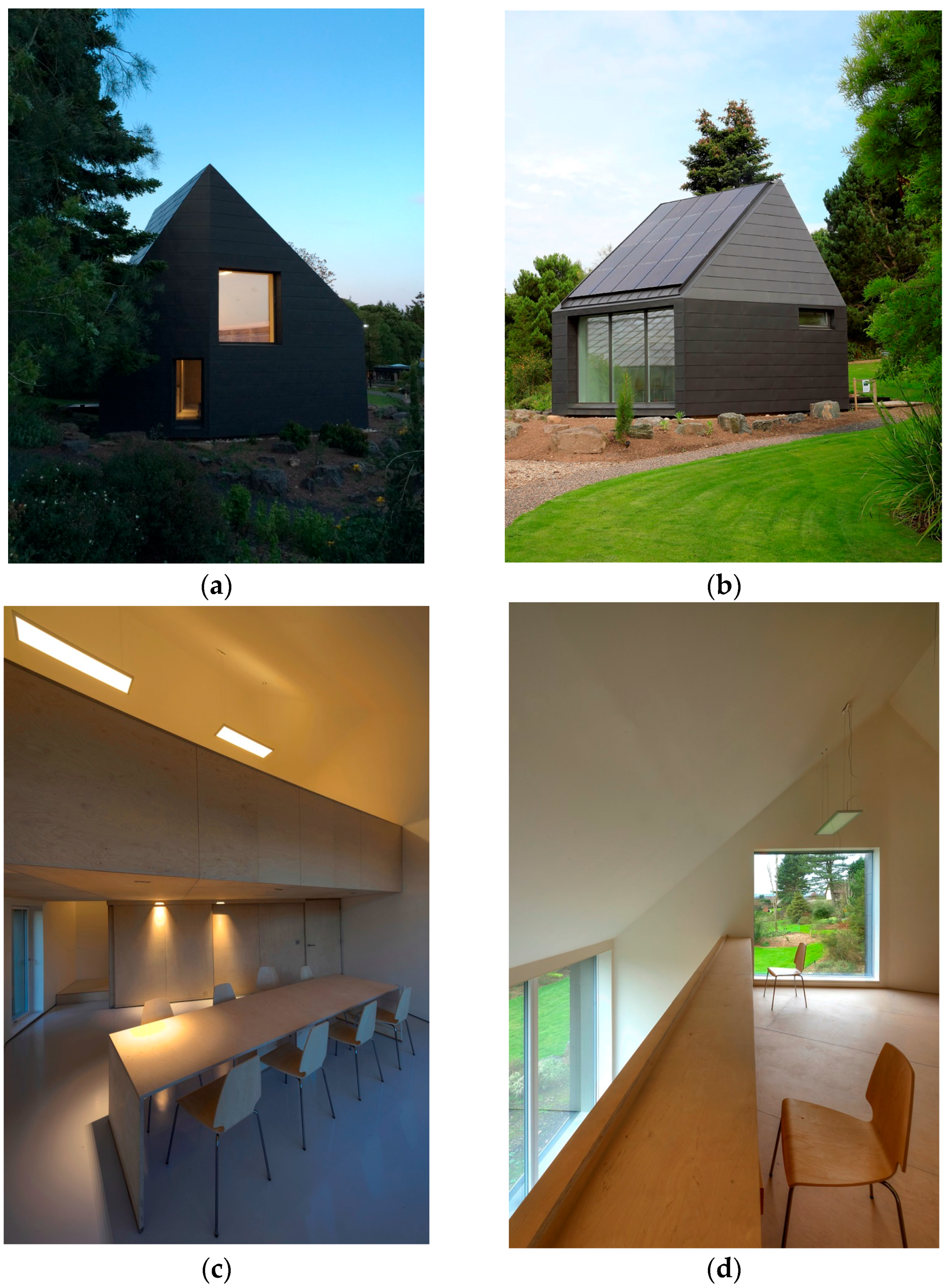
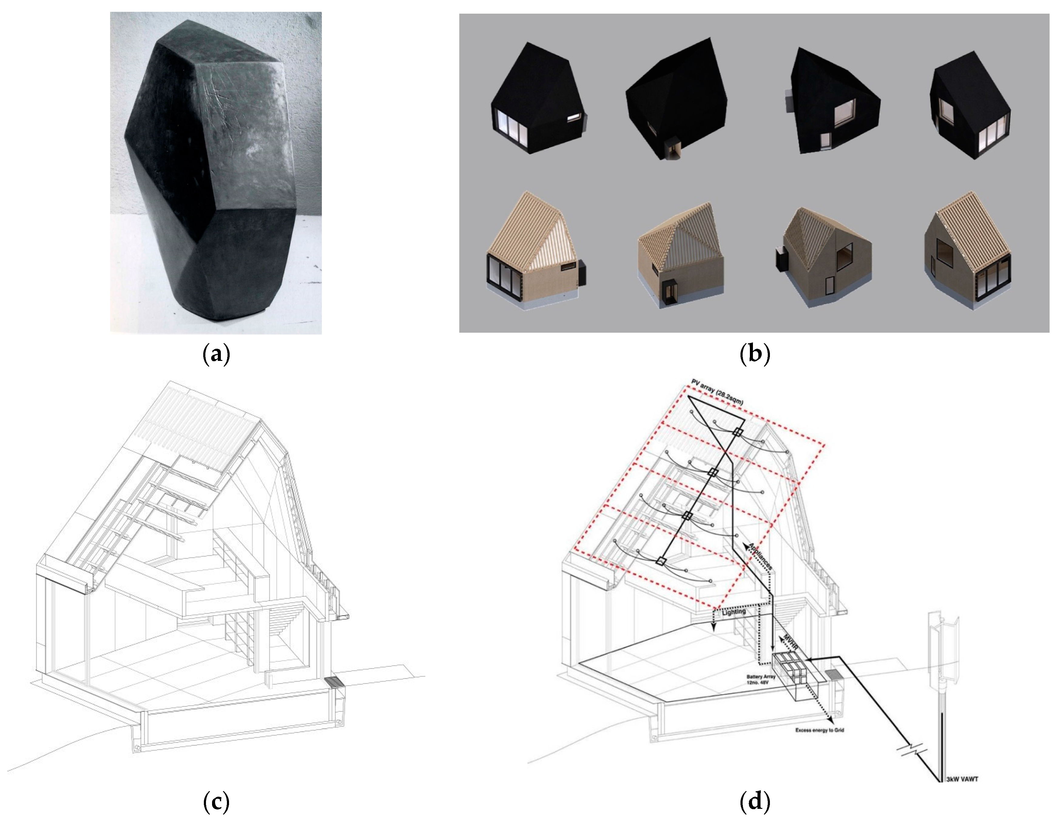
3.3.2. Formal and Aesthetic Design Principles

The final building design is a synthesis between aesthetic considerations, form factor and energy generation. The crystalline shape has been developed to respond to the different views and spaces within the garden and the technical requirements of energy conservation and renewable energy generation. The latter required a majority of south facing glazing and a 40 degree, 28.2 m2 south facing roof area for the PV. The abstract nature of the resulting geometry has the presence of an ‘erratic boulder’ within the landscape, inspired by the “CUBE” an abstract sculptural work by Alberto Giacometti in 1933 [30] (Figure 7).
Externally this form presents as a composition of aggregated internal and external spaces articulated and unified by the continuous faceted surface. Built over one-and-a-half levels, the space internally is carefully segregated into three volumes with different programmatic functions. A service zone to the north of the plan contains entrance lobby, mechanical services and kitchenette. The main ground floor area is a flexible multi-function space for studio, meetings and exhibition. The mezzanine level is a private space contained within the steeply sloping roof pitches for working and storage. The positioning of windows is precisely controlled between consideration of passive solar gain, views and the external form. The open plan arrangement facilitates air movement and heat transfer through stack effect. Natural cross ventilation is achieved via two opening windows, one located in the west elevation at the bottom of the stairs and the other on the east elevation at the top of the stairs. The surface facets that make up the crystalline form create simple angular junctions between surfaces potentially simplifying thermal detailing by reducing the potential for thermal bridging and improving air tightness. It is expected that the dark surfaces of the zinc cladding when exposed to sun will tend to depress the effective U-Value lower, or even below zero to indicate net gain, and the PV array will similarly lose some heat while generating to the underside. The footprint or plan profile reduces to the north side, hence the north-facing roof and wall surfaces also reduce to limit areas of maximum temperature difference.

4. Low-Embodied Energy Construction Principles

The construction solutions adopted in the studio were driven on the one hand by the embodied CO2e of materials and their transportation [31], the availability of the materials within the limitations of the funding of the research and aesthetic considerations. The two principle areas of innovation in the studio are in the timber superstructure and in the foundation system. A simplified Life Cycle Analysis (LCA) of the principle construction elements (foundations, walls, roof, internal structure and finishes) was undertaken following methods adopted by [32,33,34,35,36]. The results indicate that the Studio’s construction generated 30.241 tonnes of CO2e, with 52% of its material mass associated with the foam concrete foundation and 24.57% with the timber superstructure and finishes. The carbon sequestered by the timber superstructure and finishes when factored into the total would lower the CO2e to 8.416 tonnes. The quantity of insulation makes a significant contribution to the total CO2e in order to achieve 0.1 W/m2K average U value, but this would be offset by operational CO2 savings due to the lower energy consumption of the building. Conventional foundation systems produced similar total emissions to the foam concrete, the latter having the advantage of being simpler to install and detail. The zinc cladding used on the facade contributed approximately 45% of the total CO2e which would be reduced if alternative lower embodied energy materials were considered and aesthetic and durability issues were less of a priority.

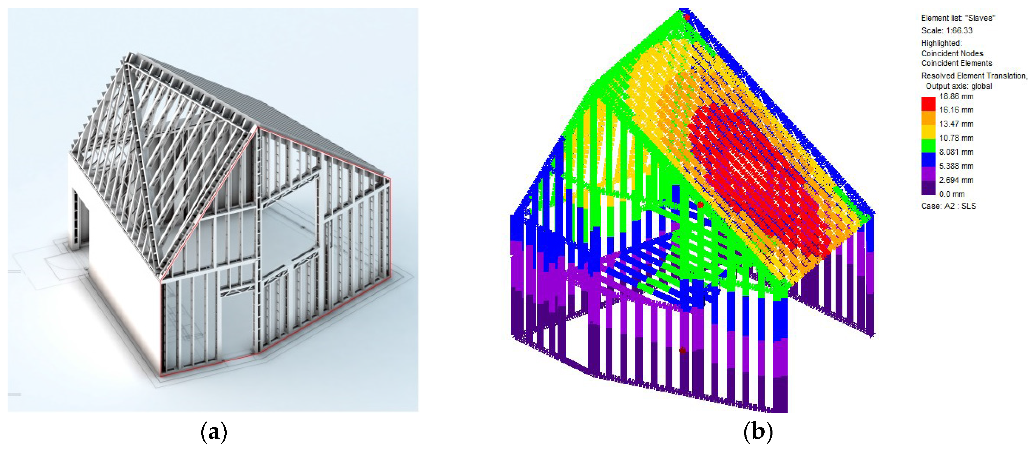
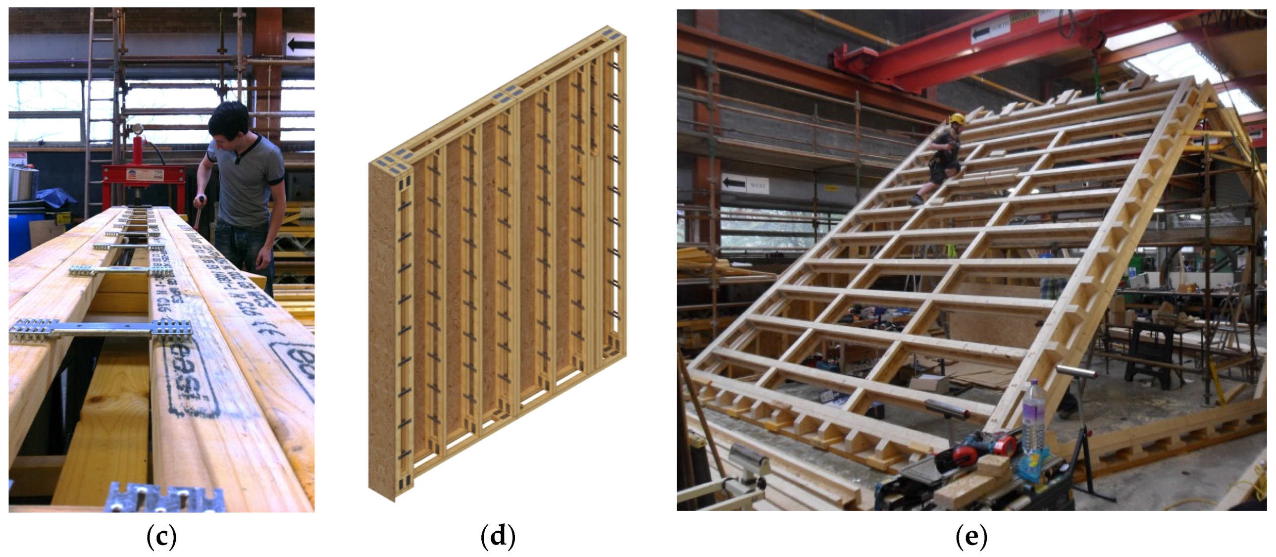
4.1. Timber Structure

Timber is the most sustainable low-carbon renewable form of construction available today, with timber-kit construction accounting for around 80% of the market in new build housing in Scotland [37]. Although Scotland has significant timber resources, the majority of timber is imported from Scandinavia and Canada, which limits the capacity for the Scottish forestry industry to up-scale. The resulting choice of construction systems and detailing was in response to developing a low cost, self-build Passivhaus standard building envelope that would optimise regional and local products and that could be simply and safely constructed by low-skilled labour without the need for mechanical plant on site. The geometry of the building provided significant challenges that required substantial innovation in the development of the timber superstructure which is a hybrid construction of proprietary timber systems and bespoke elements (Figure 8). The Alpine SpaceStud® and SpaceJoist® framing systems had recently been developed by Cullen Building Products and ITW Industries to meet increased thermal requirements of the Building Regulations and the Code for Sustainable Homes [38]. The SpaceStud® (ITW Industries, Glenrothes, UK) used for vertical load bearing elements in the wall construction, is a wall stud utilizing standard stock sizes of Scottish timber for two vertical 38 mm × 44 mm timber chord sections that are connected by pressed steel separators. The 202 mm wide cross section accommodates thicker insulation, providing low U-values and reduced thermal bridging due to the discontinuity of the section. The wall cassettes were preformed from 1.2 m wide × 3.0 m high open-panels, and comprise SpaceStuds® at 400 mm centres, SpaceJoists® (ITW Industries, Glenrothes, UK) used for lintels over openings and 9 mm OSB sheathing to both faces.
The roof is a plate structure assembled from individual elements on site, comprising 225 mm deep James Jones timber I-Section joists (JJI-Joists®) (James Jones Ltd, Larbert, UK), with 45 mm × 90 mm timber chords and 12 mm thick OSB webs [39]. The frame was analysed in Oasys GSA software. The roof plates required stiffening the junctions between the different facets which resulted in a hybrid construction with a Laminated Veneer Lumber (LVL) ring-beam at the wall head and composite triangular shaped LVL/JJI-Joist beams at the plate junctions. Plates are infilled with JJI-Joists at 600 mm centres and joined to the ridge beams using proprietary steel connectors and sheathed to both faces with 9 mm OSB. Originally the rafters in the south roof were arranged from top to bottom but were subsequently changed to span in the lateral shorter span to reduce bending which is indicated in red in Figure 8b. The floor construction comprises 245 mm × 90 mm JJI-Joists at 450 mm centres running between a glulam beam above the service wall and a bespoke 1 m deep × 120 mm wide CLS/plywood box truss that supports the front edge of the mezzanine floor and ties the east wall and west gable giving racking stability. The truss is supported on the east and west wall frames on cripple studs.

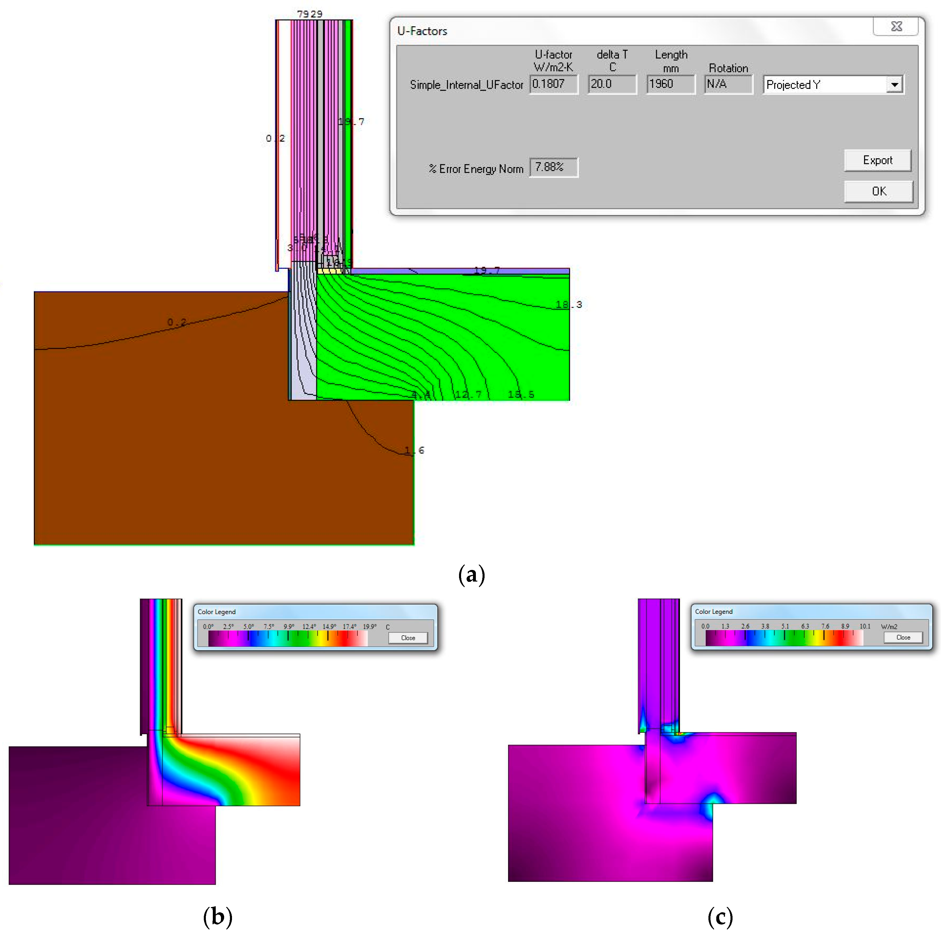
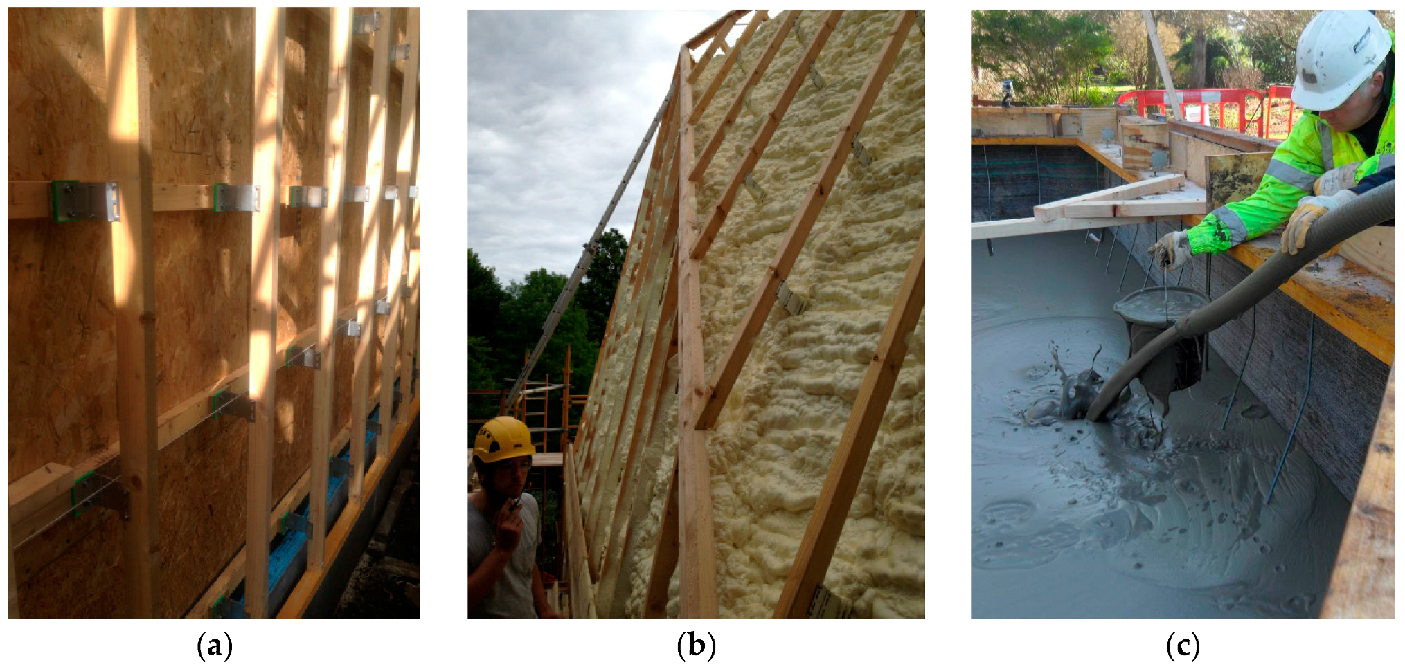
4.2. Thermal Envelope Design

The thermal envelope incorporates a 477 mm thick sprayed Icynene® (Icynene, Mississauga, Canada) LD-C-50 insulation, a non-toxic, water blown, vapour permeable, open-cell foam [40]. This has no ozone depleting agents such as CFCs (chloro-fluero-carbons), HCFCs (hydro-chloro-fluero-carbons), HFAs (hexa-fluero-acetones) or harmful flame retardants such as PBDEs (penta-bromo-diphenyl ethers) and a BBA-Certified conductivity of 0.039 W/mK. The insulation was sprayed onto the frame in two stages, the first spray encapsulated within the frame between the two layers of OSB ensured that all voids were filled. The inner structure is bounded by a services gap covering a Glidevale VC Foil® (Glidevale, Sale, UK ) air tight membrane with overlapped and taped seams, encapsulated in 12 mm plaster board on timber battens and skim coat plaster finish [41]. The second spray of 175 mm Icynene® (Icynene, Mississauga, Canada ) was over-sprayed onto the outside of the structure which provided a second airtight seal tested initially to 0.6 air changes per hour (Figure 9b). The frame is surrounded by a secondary timber exoskeleton supported by Nvelope® (Nvelope Rainscreen Systems Ltd., Welwyn Garden City, UK) adjustable length thermally broken aluminium brackets [42] (Figure 9a). These were necessary to take up the variable ventilated wall depths of the shell which ranged from 275 mm to 550 mm, the depth being determined by the reciprocal geometry of the building form. The timber purlins support 22 mm timber sarking boards, breather membrane and the zinc cladding. Windows and doors are triple glazed NorDan NTech® 0.7 (NorDan, Moi, Norway); although not Passivhaus certified, NorDan claim the windows attain U Values as low as 0.7 W/m2K [43]. Services were concentrated into one 300 mm diameter service duct in the battery void, which was sealed using RISE RAPID® Duct Seal (CSD Sealing Systems, Cramlington, UK , city , country) an airtight sealing system allowing future service penetrations to be made without compromising airtightness [44].

4.3. Foam Concrete Foundation Slab

Foundation construction in Passivhaus buildings can be more complex and expensive than conventional foundation design due to the necessity to maintain the capacity to transmit superstructure loads to the ground whilst eliminating thermal bridging. Lightweight foamed-concrete materials are usually used in civil engineering large void-fill applications or in the construction of lightweight bridge decks and road foundations [45]. They are highly air entrained sand cement or cement only slurry with greater than 20% air by volume. The air is created by the introduction of a pre-formed foam with encapsulated bubbles of 0.3–1.5 mm diameter. Strength is normally between 1 N/mm2 and 10 N/mm2, with strength increasing with density. By varying the air content in the material very high insulation properties can be achieved but at the expense of a reduction in mechanical properties [46]. In the studio, a monolithic slab of in situ poured foam concrete provides thermal insulation and structure in a single material (Figure 9c).
The slab was poured in two stages into a plywood formwork, with the timber kit being anchored by in-situ 10 mm·stainless steel threaded bar mounted in a 200 mm × 45 mm LVL soleplate pre-attached to the top of the form work and connected to a continuous steel uni-channel located in the base of the foundation. Due to the air void system in foamed concrete water absorption is higher than normal concrete, with values between 3% and 9% by weight being typical for densities between 1700 kg/m3 and 500 kg/m3. To protect the slab a CETCO® (CETCO Mineral Technologies Europe Ltd., Wallasey, UK) self-bonding, composite needle-punched sodium bentonite/geotextile waterproofing tanking system was used which forms a monolithic waterproofing membrane when hydrated [47]. A 40 mm thick anhydride self-levelling screed was required to protect the surface of the material to provide wear resistance, which was finished with Sikafloor® (Sika Services AG, Pfaffikon, Switzerland) -2530 W, two part, water dispersed, solvent free, coloured, epoxy resin coating [48]. The higher thermal mass of the screed is designed to take advantage of direct solar gain from the south facing façade.
The slab using a 600 kg/m3 sand/cement mix achieves a U Value of 0.098 W/m2K at 1 m thick but requires 200 mm thick EPS perimeter insulation at the edges providing a perimeter U Value of 0.112 W/m2K. The critical thermal junction in the slab is at the interface between the slab and timber kit where an LVL soleplate is used to distribute loads from the kit and tie this to the slab in the event of uplift. LBNL THERM 6.3, 2D heat flow analysis software was used to model the interface and to investigate various ways of isolating the soleplate from the slab, including a mortar bed, foam strip and bedding the soleplate directly on the slab. The latter was found to be most effective giving a Psi Value of −0.0165 W/mK, which reduced the SSHD by 1 kWh/m2/a when accounted for in PHPP (Figure 10). Additional modelling was needed in the areas of reduced slab wall thickness around the battery void and service duct opening. It is anticipated that the further improvements could be made to the slab/kit interface if a thermally broken soleplate had been used. The slab and screed have been instrumented with thermocouple wires to assess future performance.

4.4. Air Pressurization Test Results

Blower Door tests were carried out by Thermal Image UK with the air leakage characteristics of the structure being determined in accordance with ATTMA TSL1−Issue 1, which is based on BS EN 13829:2001 with enhancements recommended by ATTMA, using an air depressurisation technique. Air was supplied to the building at a variety of flow rates to create subsequent pressure differentials between the internal and external environment of the structure under positive and negative pressures. Air moving equipment was utilised to provide the required airflow and pressure differentials were constantly measured and logged. The air temperature inside and outside was measured, along with the external wind speed and barometric pressure. The pressurization tests were carried out using a temporary seal to the service duct which could be seen to be leaking during the smoke test. The airflow rate at a pressure differential of 50 Pa was determined, expressed as an airflow rate per m2 of building envelope. The air changes per hour (average) results from three tests were 0.531ach@n50, within the Passivhaus maximum limit of 0.6ach@n50. Further improvement would be expected with a sealed service duct.

5. Mechanical Systems

As would be expected in a small building the mechanical services are comparatively simple, the main requirements being electrical distribution, lighting, heating and ventilation, hot and cold water supply, renewable energy generation and storage. In addition, there was the need to consider monitoring of the environment, fabric and building occupants. Due to expediency and timescales it was decided to use conventional 240 V mains AC electrical distribution, although a more innovative DC system had been considered earlier in the project. Alternative designs for heating and hot water supply had also been previously investigated with solar thermal roof panels and hot water storage being an option, but due to space constraints this was subsequently ruled out. Eventually, it was decided to focus development on an all-electrical system for the building which had the advantage that monitoring and controlling electrical consumption would be easier to manage and determine in the future.

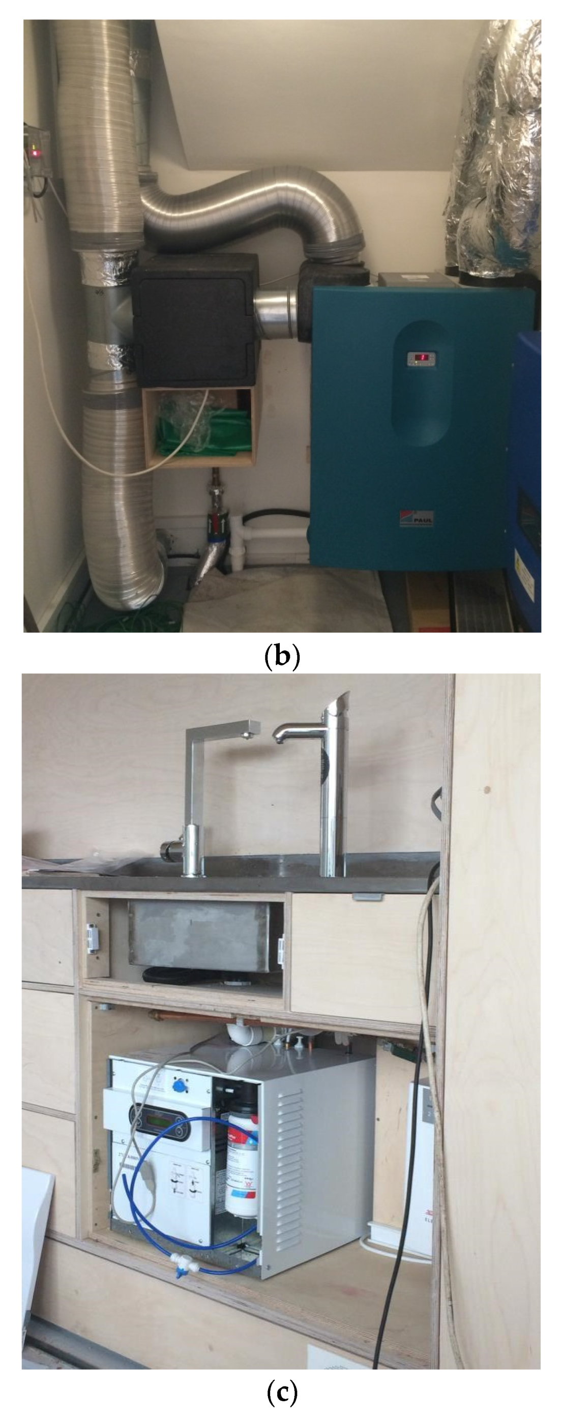
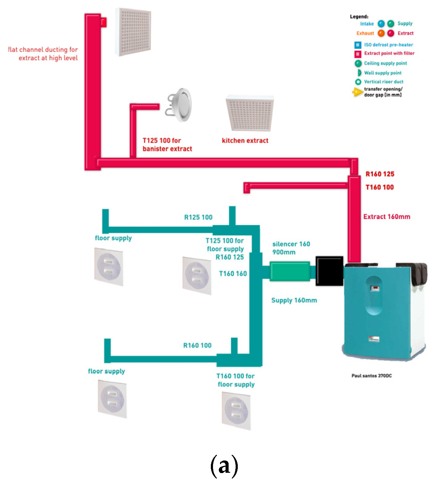
5.1. Mechanical Ventilation Heat Recovery

A Paul Santos 370DC Mechanical Ventilation Heat Recovery (MVHR), balanced supply and ventilation system was specified, comprising a counter-flow heat exchanger at a heat recovery rate of up to 90%, supplied by Paul Heat Recovery (Figure 11) [49]. PHPP calculations determined that an auxiliary heating system was unnecessary and that additional active heating could be achieved via a 1 kW electrical post heater fitted to the MVHR supply air duct situated adjacent to the MVHR unit. A Comfo Sense 67 control unit provides programmable automatic and manual operation of the MVHR in conjunction with a Honneywell DT90E digital room thermostat, wall-mounted in the kitchenette. All the supply and extract ducts are contained within the central service wall adjacent to the plant room and built into bespoke furniture storage units. This ensures that all the duct runs are direct and as short as possible while being concealed and easily accessible. Two T160 100 supply ducts are mounted in the skirting unit in the kitchenette and a further two outlets supply the mezzanine, mounted in the skirting of the storage unit. Extract is via one T160 100 mounted at high level in the kitchenette, a T125 100 mounted in the banister rail facing the stair void and a further T160 at the apex of the roof connected to a flat duct within the service void of the west gable.

5.2. Lighting and Controls

Lighting was supplied and designed by IGuzzini and uses a range of very low-energy, high specification big-ballast LEDs [50]. The lighting design was developed to minimize power consumption, achieve optimum Lux levels on working surfaces and enhance interior aesthetics. Lighting controls were designed by Honeywell and use programmable PIR and Photocell sensors to control energy use [51] The lighting is organized into six zones: plant room, exterior, lobby, ground floor, kitchenette, stair well and mezzanine. The lobby is controlled using a ceiling mounted PIR while the ground floor recessed downlights and mezzanine pendant uplights/downlights are controlled via ceiling mounted Photocell-PIRs, with a manual switched override. The plant room and stair well uplighters are switched manually and the exterior lights at the entrance are on a manually set Levante TM8GP-24 timer adjusted seasonally. Emergency lighting is installed in the stairwell stringers and mezzanine ceiling powered by dedicated individual Li-Ion battery back-up.

5.3. Water Supply

The water supply currently is mains fed, although the original intention was to harvest water from the south roof using a 1137 litre, rainwater harvesting systems using a Balmoral Hydrostore® (Balmoral Tanks Ltd., Aberdeen, UK underground tank and pump this to the building through a filtration system still to be developed providing autonomy from the mains supply ([52]. Currently filtered boiling and chilled drinking water is supplied via a ZIP Hydro Tap® BC200/175+ (Zip Industries, Sydney, Australia)and instantaneous hot washing for hand and dish washing is supplied via a ZIP IHW CEX-U In Line Heater® (Zip Industries, Sydney, Australia) ZIP, 2016 [53]. The Hydro Tap® has a power rating of 2.8 kW and has two energy conservation modes with an integral programmable 24 h 7 day timer allowing behaviour patterns to be pre-defined and an inactivity sleep mode allowing the system to be powered down. The In Line Heater® has a power rating of 9.8 kW and programmable settings for supplying water between 20 °C and 60 °C. Both systems are designed to conserve energy by precisely controlling supply volumes and outlet temperatures and minimizing energy losses through direct supply.

6. Energy Consumption, Generation, Storage and Controls

The primary aim of the project is to understand how different renewable energy technologies operate together to achieve “autonomy” and how these systems can be optimized to manage energy consumption behaviour without oversizing either the energy generation or storage elements of the system. While predictions were made in terms of external environmental factors (solar insolation, wind speeds) and the energy needs of the building occupants it was not possible to definitively quantify the relationship between these in terms of the efficiency of the system. A best “fit” was developed and this was used to make the current design decisions on the energy system. The energy budget of the Studio may be broken down as follows: Thermal energy gains/losses; Electrical energy requirements; PV generation; Wind generation; Energy Statistics; Building management. As the project has not yet reached completion, there are currently no substantive operational data on which to judge performance. The following results have been developed through independent research studies carried out by students assigned to the project using proprietary software packages [54].

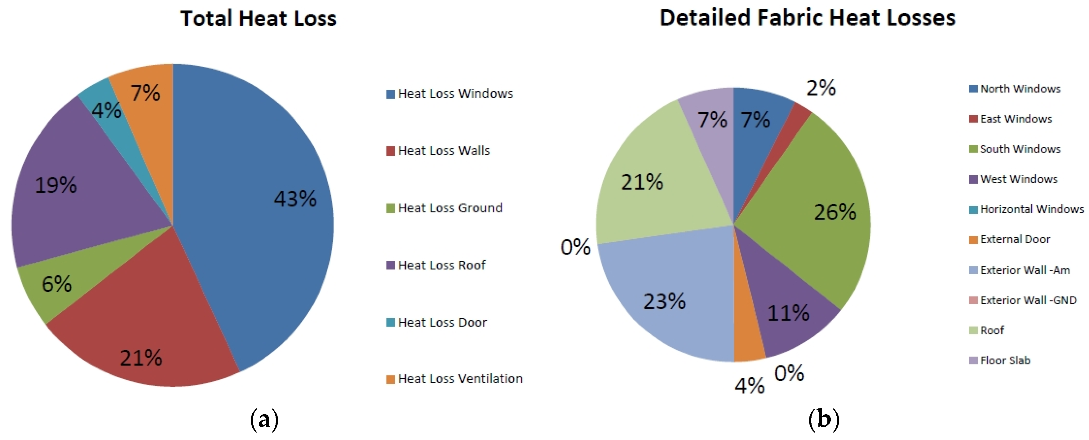
6.1. PHPP Analysis—Thermal Gains, Losses and Ventilation

Initial estimates of the thermal performance of the Studio were developed in the Passivhaus Planning Package (PHPP 2007 Version 2.1.1) which provides minimum compliance values across a range of criteria. PHPP compiles a detailed description from user input of the building envelope and material thermal properties site, orientation, occupancy, ventilation, electrical goods and utilisation, local climate, and desired interior temperature. Heat loss due to transmission + ventilation, and heat gain due to solar radiation + internal sources (occupants and appliances) may thus be calculated [29]. It was assumed that the Studio was on a flat site and there were no overshadowing elements allowing all solar gains available to the site to be utilised. The calculated U-Values for the building fabric were; Walls 0.108 W/(m2K), Roof 0.099 W/(m2K), Foundation (main area) 0.098 W/(m2K) and Foundation (perimeter) 0.112 W/(m2K) with the fabric U value average being 0.17 W/(m2K). The average U-Values for the Windows is 0.82 W/(m2K). Shading was defined as 0.2 m for window reveal and overhang depths. Additional seasonal shading such as blinds, blocking 50% of the solar heat gain to the south elevation was calculated. This was determined by defining a maximum temperature swing of less than 3 Kelvin (PHPP guidance), eliminating overheating when combined with adequate summer ventilation in Scottish climates. A Paul Santos 370DC Mechanical Heat Recovery Ventilation unit with an efficiency rate of approximately 94% was used. The construction was considered to be thermal bridge free but additional modelling of the slab/kit interface was carried out due to the atypical construction. East of Scotland climate data supplied by BRE was used in the modelling. The annual heat demand is the annual sum of (heat loss—heat gain). The calculated mean annual value obtained for the Studio was 10 kWh/m2/a which lies within the Passivhaus limit with the fabric heat loss proportions detailed in (Figure 12). The analysis indicated that a 1 kW electric post-heater on the MVHR unit would be sufficient to offset the heat deficit in winter months, conditional on the availability of electricity. The PHPP analysis predicted a significant likelihood of overheating in summer months but with a relatively benign northern maritime climate and not excessively high summer temperatures due to latitude, management of the internal environment should be achievable by natural ventilation (stack and cross-ventilation), night-time purging and/or reducing solar gain by means of shading. Detailed results are contained in the Supplementary Materials.

6.2. Electrical Loading

The main contributions to the electrical load are as follows: MVHR unit and post-heater, lighting, laptops + chargers, mobile phone charging, refrigerator, water heating (ZIP Units), Building Management System. By spreadsheeting individual consumption and utilisation factors an estimate of the typical load may be made, which amounts to some 6.6 kWh/day to 8 kWh/day. There is a high degree of variability depending on occupancy, nature of tasks, time of year, and day of week. These figures have been based on 4 people using the building 9-5, 5 days a week (Figure 13).

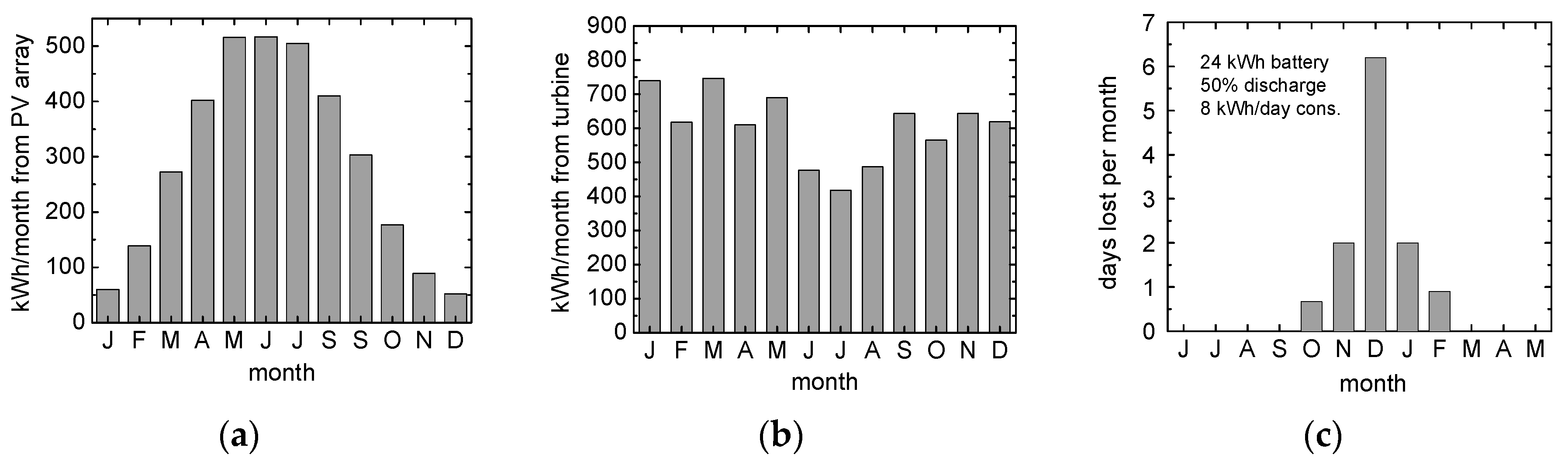
6.3. PV Electrical Generation

A combination of a 28.2 m2 roof area and 20 number, 14% efficient Siemen’s polycrystalline silicon modules [55] grid connected via a SMA Sunny TriPower 5000TL Inverter provides an installed PV array capacity of around 4.8 kWp. The insolation SAP design value for eastern Scotland is 850 kWh/m2/a, leading to a projected yield of 4200 kWh/a. However, the 56 degree latitude of Dundee results in highly-seasonal variations in output. The summer months yield > 15 kWh/day, which is more than sufficient to run the Studio on most days. However, in winter this falls to 1.5 to 3 kWh/day, a serious shortfall considering the projected need for post-heating of the MVHR at this time.

6.4. Wind Turbine Electrical Generation

The wind-turbine which has still to be installed will be located some 15 m west of the glasshouse, on a 10 m mast with an open aspect to prevailing south westerly winds. It was originally proposed to use a “Giromill” vertical-axis rotor type, such as the Aeolos-V 3 kW [56], selected since they are considered to be quieter and less obtrusive—the turbine operates in a public area, and there is housing within 20 m of the site. A further advantage is the potentially superior performance of a VAWT operating in the gusty wind conditions found in suburban areas. A meteorological station operated by a colleague is located some 1 km from the site [57]. Insolation and wind records at 5 min intervals from 2003 onwards were used to estimate the output from both the PV array and the VAWT, in the latter case using the power vs. wind-speed conversion curve in the brochure. The projected monthly output is shown in (Figure 13a,b) and it should be noted the complementary form to the PV curve—wind power shows a shallow minimum output over the summer months.

6.5. Energy Statistics

An important advantage of having local meteorological data when simulating the performance of the Studio system is that the records may be combined directly to estimate the total generated power (PV + wind) at any instant at the Studio site. This provides an accurate statistical record of power fluctuations on a timescale of minutes to days. From Figure 13c it can be seen that the combined monthly generation lies between 650 and 1000 kWh. The generation fractions are reasonably well-balanced between March and October, and thus a daily shortfall in one might be compensated by the other. In the winter months however, there is strong reliance on wind, which has implications in an energy-autonomous system. Using the 9 years of local data has enabled the effects of intermittency to be studied with some degree of authority. As a starting-point a constant daily load of 8 kWh throughout the year denominator’ (which includes a constant factor for the post-heater of around 2 kWh/day) and a battery capacity of 24 kWh were assumed. A maximum discharge level of 50% was stipulated, effectively providing 1.5 days of battery reserve. A simple strategy of shutting down all consumption when the 50% battery charge limit was exceeded until the battery was fully re-charged was adopted. Despite the fact that the monthly consumption is some 240 kWh (including weekends), and generation in December is over 600 kWh, the probability that power will be lost over the month is approximately one day in five, with other predicted outages in October, November and January.
Because PHPP 2009 uses calibrated regional weightings for estimating the RE generation for PV and Wind components, it is not possible to definitively confirm if the studio complies with the new PH standards without modelling this in the new software. However, a simplified PER value can be computed on a monthly basis using the monthly figures detailed above, from the equation: PER = Energy supply from renewable sources/Final energy demand at the building. The smallest PER value, as expected from the number of drop-out days (6) is December (PER = 2.70), and the largest is in May (PER = 4.86). However, the December figure is likely to be worse if the post-heater runs for more than 2 h/day, and the coarse monthly calculation method inevitably hides the true picture in terms of the system’s autonomy due to erratic periods of calm weather in winter (of the order of 2 or more days of low wind simultaneously).
Alternative strategies could be adopted to mitigate this whereby energy shortages are anticipated and consumption adjusted by various means. In a typical off-grid system, a diesel generator would normally be used to make up the shortfall in the absence of a more stable renewable source such as hydro-electric [58]. In our case the system is in fact grid-tied of necessity, because we are exporting excess electricity, so the grid can effectively play this role. Over the nine-year period of data records (2003–2011), the average annual electricity consumption of the Studio is around 3000 kWh, the export to grid is some 7000 kWh, and import from grid (in the above role) is 120 ± 50 kWh. The export arrangements will in practice be made more challenging by the fact that there are no NEL/TÜV-certified VAWTs of a suitable capacity available and arrangements will need to be made to export the wind-generated electricity for use only within the confines of the Botanic Gardens. The logistics and practicalities of this arrangement are currently under investigation. An alternative strategy suggested by PH 2009 is to balance short-term and seasonal storage. Therefore, in this context, around 8 days of excess summer electricity could be abstracted to produce sufficient hydrogen to regenerate 120 kWh of electricity from a fuel cell in the winter months. This should enable energy autonomy to be maintained throughout a typical annual cycle. The seasonal store could, for example, be used in 12 kWh “blocks” to re-charge the battery when it falls below 50% maximum.

6.6. Building Management Systems

The conceptual building management and monitoring system will be a key feature of the Studio in the future. The requirement for comprehensive always-up monitoring of the physical status of the building is essential in order to satisfy one of the major goals of the project, which is that it will function as a “live-in lab” for three years or more following completion. This will involve monitoring occupant activities and interactions as well as temperatures, lighting levels, etc., so that a picture of the way occupants behave and how the building needs to accommodate their behaviour, and vice-versa, might be developed. Data collected will be available on-line to all participants in the project and to authorised external bodies. While a detailed specification of the system is under development, and its sophistication will depend on future funding and in-kind support, the overarching requirements are as follows:
  • Management of temperature and comfort via MVHR, blinds, natural ventilation;
  • Conditioning and control of electricity flows from PV and wind sources, use within Studio, export, and import;
  • Implementation of a range of power management strategies, pre-defined, predictive, adaptive
  • Passive monitoring of systems and sub-systems, including arrays of temperature and light sensors, breakdown of electricity use by product in real-time;
  • Monitoring of weather conditions, e.g., wind speed and direction, insolation, rainfall, outdoor temperature and humidity for thermal calculations;
  • Monitoring of user occupancy, activity and comfort.
It should be borne in mind that measurement, control and data management functions will themselves incur an energy cost, and indeed may also interfere to an extent with the “normal operation” of the studio as a workplace.

7. Discussion

The most significant and challenging aspect of the research has been in the development of the autonomous renewable energy system which has been designed to achieve “self-sufficiency”. Despite the 1.5 day autonomy of the battery sizing there are significant predicted outages in winter which highlights the core problem of “off-grid” generation systems (Wind/PV) at high latitudes having such a wide spread of monthly output. In a next phase of modelling a sensitivity analysis on battery size, discharge level, demand side regulation would be needed to determine if autonomy is achievable. The base assumptions used in the energy analysis were made early in the project and since this analysis was performed, changes have been made to specifications and final occupancy that will inevitably affect the base loads. More precise figures are still fluid, but are likely to have minimal significant bearing on the key predictions, outcomes and scenarios thus developed, namely:
  • Wind + Solar works surprisingly well for 8 months of the year (but is seriously oversized on average basis) with the energy balance being most strongly affected by the VAWT due to becalmed days in winter;
  • Achieving annual electrical autonomy is a very difficult task at a latitude of 56.54°N, without improved storage but there is tantalizingly large average excess energy generated each month;
  • A larger battery size could reduce the problem (but it would likely be unfeasibly large to statistically eliminate outages due to 5 winter days of low/no wind);
  • A strict regime on “critical days” energy usage may help (using weather forecasts to trigger these);
  • A seasonal store of “electricity”, even an inefficient one, would be a significant help but would need to be around 100 kWh in size—potential options being hydrogen, pumped water, biogas reactor fed by waste heat from electricity or other organic power sources?
A 5.0 kWp PV system was installed and commissioned in June 2014. It is slightly up-rated from that upon which the modelling described in section 5.2 was based. At the time of writing it has been operational for 1.75 years, and has generated 8690 kWh AC. Ignoring the fact that the second annual cycle has not been completed, these figures indicate a pro-rata specific yield of 993 kWh/kWp/a. We consider this to be a satisfactory outcome, in keeping with similar installations located on well-disposed sites in east Scotland over this period.
Work has recently started on the development of a Arduino® (ARDUINO LLC, Somerville, USA) environmental monitoring unit that will combine LUX, temperature, humidity, airflow and CO2 sensors. The floor slab has been instrumented using thermocouple cables and a data logger will be used to record the thermal performance of the foam concrete and thermal storage behaviour of the screed. In the meantime, LASCAR EL-USB-1 temperature and humidity data recorders have been installed set to record at one minute intervals over the past 18 months. These were positioned in the plant room, ground floor kitchenette and on the mezzanine balustrade. The data recorded was very variable giving a high summer temperature peak of 33 °C and a gradual decline in temperature from around mid-November to mid-February with a lowest recorded night time temperature of 6 °C. Since the commissioning of the mechanical systems in late August, and even with a very “free-floating” occupancy, no natural ventilation, little internal heat gains and the MVHR on a standard operating setting, the diurnal temperatures have begun to stabilize although the building is showing a tendency to overheating on hotter summer days. There is some variability in temperature gradients within the building with the plant room recording temperatures 3–4 °C higher than the other spaces. The mezzanine and ground floor areas show similar temperature patterns suggesting a free flow of heat most likely due to stack effect (Figure 14). Introduction of an extract within the plant room would be beneficial in utilizing the heat generated from the mechanical equipment over the winter months and reducing higher summer temperatures using the MVHR bypass facility.

8. Summary

This paper has described the conception, design and construction of the Macro Micro energy-self-sufficient prototype laboratory at the University of Dundee, its present status, predictions obtained from modelling of thermal properties, PV and wind electrical generation systems, and has outlined some future plans. The building concept has been developed as an energy autonomous solution operating an all-electrical system powered from near-zero emission renewables including a 5 kWp PV array, 3 kW VAWT and 24 kWh Lithium-Ion battery store. It was designed to the 2007 Passivhaus standard, with calculations indicating the construction will achieve 10 kWh(m2a) specific space heat demand, although certification was not possible due to funding restrictions. This has been achieved partly through an optimization of the geometry to give a low Form Factor, optimized solar orientation and the specification of a high performing thermal envelope. Innovations incorporated in the construction include the use of Scottish small section timbers in a thermally broken open panel cassette and a 1-m deep foam concrete slab foundation system providing very low U values (0.1 Wm2k) and the elimination of thermal bridging which reduced the predicted space heat demand by 1 kW/m2/a. Other sustainable measures have been incorporated within the design including water harvesting, direct heating water supply, LED lighting incorporating PIR and daylight controls. Although the energy system has yet to be completed, modelling indicates that the total annual renewable energy generated, will significantly exceed the total energy consumed (regulated and unregulated) in the building. Our calculations predict that the daily total energy demand can be satisfied from the renewable system in combination with short-term storage, but a shortfall is predicted for 12 days of the year occurring between October and February when the PV component is least effective. We expect in the future this will be mitigated through smart systems using predictive data to manage demand at critical periods and/or a small seasonal storage system such as a hydrogen fuel cell with the capacity for 120 ± 50 kWh of electricity production. The project is very much an on-going one, and will shortly move to the next phase involving the implementation of medium-scale energy storage, energy controls and environmental monitoring once further funding has been secured. The longer-term intention is that the project will become a “live-in-laboratory” for a wide range of research activities including: Experimental studies of Passivhaus performance; renewable energy management strategies; building automation and adaptive control.

Supplementary Materials

The supplementary materials is available online at https://www.mdpi.com/2071-1050/8/6/500/s1.

Acknowledgments

The authors gratefully acknowledge the contributions of students of the University of Dundee who have worked on the Macro Micro Studio project, many of whom have given freely of their time over and above the requirements of their academic programmes. Without them it simply would not have existed. Thanks are also due to faculty staff, technicians and administrative support, who have supported the project and invested time and energy. We are particularly indebted to Alasdair Hood, Curator of the Botanic Gardens, for taking such a risk on the outcome. The in-kind contributions of industrial partners, manufacturers and suppliers, detailed on the project website, have made construction of the Studio a reality.

Author Contributions

All authors have contributed equally to the writing and developing of research material used in this paper.

Conflicts of Interest

The authors declare no conflict of interest.

References

  1. Hitchin, R. A Guide to the Simplified Building Energy Model (SBEM). What It Does and How It Works; BRE Trust: Watford, UK, 2008. [Google Scholar]
  2. Kelly, S.; Crawford-Brown, D.; Pollitt, M.G. Building performance evaluation and certification in the UK: Is SAP fit for purpose? Renew. Sustain. Energy Rev. 2012, 16, 6861–6878. [Google Scholar] [CrossRef]
  3. MacKay, D. Sustainable Energy without the Hot Air; UIT Cambridge Ltd.: Cambridge, UK, 2009. [Google Scholar]
  4. European Community. Directive 2002/91/EC of the European Parliament and of the Council of 16 December 2002 on the Energy Performance of Buildings. Available online: http://eur-lex.europa.eu/legal-content/EN/TXT/?uri=CELEX%3A32002L0091 (accessed on 18 May 2016).
  5. European Community. Directive 2010/31/EU of the European Parliament and the Council of 19 May 2010 on the Energy Performance of Buildings. Available online: http://eur-lex.europa.eu/legal-content/EN/TXT/?uri=CELEX%3A32010L0031 (accessed on 18 May 2016).
  6. European Community. Directive COM (2013) 483 of the European Parliament and of the Council of 28 June 2013 on Progress by Member States towards Nearly Zero-Energy Buildings. Available online: ec.europa.eu/transparency/regdoc/rep/1/2013/EN/1-2013-483-EN-F1-1.Pdf (accessed on 19 May 2016).
  7. Groezinger, J.; Boermans, T.; Ashok, J.; Seehusen, J.; Wehringer, F.; Scherberich, M. Overview of Member States Information on NZEBs: Working Version of the Progress Report—Final Report; European Commission Project BUIDE14975; Ecofys: Cologne, Germany, 2014. [Google Scholar]
  8. Musall, E.; Voss, K. Zero Energy Buildings—A Term with Various Meanings; Detail Green: Munich, Germany, 2012; pp. 70–73. [Google Scholar]
  9. Marszal, A.; Heiselberg, P. Zero Energy Building Definition—A Literature Review; Joint Project—Task 40/Annex 52, Net Zero Energy Buildings, Solar Heating and Cooling Programme; International Energy Agency: Paris, France, 2010. [Google Scholar]
  10. Kibbert, C.; Fard, M. Differentiating among low-energy, low-carbon and net-zero-energy building strategies for policy formulation. Build. Res. Inf. 2012, 40, 625–637. [Google Scholar] [CrossRef]
  11. Hernandez, P.; Kenny, P. From net energy to zero energy buildings: Defining life cycle zero energy buildings (LC-ZEB). Energy Build. 2010, 42, 815–821. [Google Scholar] [CrossRef]
  12. Pless, S.; Torcellini, P. Net-Zero Energy Buildings: A Classification System Based on Renwewable Energy Supply Options; Technical Report NREL/TP-550-44586; National Renewable Energy Laboratory: Golden, CO, USA, 2010. [Google Scholar]
  13. Peacock, A.; Owens, E.; Roaf, S.; Corne, D.; Dissanayake, M.; Tuohy, P.; Stephen, B.; Galloway, S. Autarkic Energy Systems: Balancing Supply and Demand with Energy Storage and Controls in Local Energy Micro-Grids. In Proceedings of the 2014 Asia-Pacific Solar Research Conference, Sydney, Australia, 29 November–1 December 2014.
  14. Abegg, B. Energy Self-sufficient Regions in the European Alps. Mt. Res. Dev. 2011, 31, 367–371. [Google Scholar] [CrossRef]
  15. Millar, G. Electricity Storage: Realising the Potential; Institution of Civil Engineers: London, UK, 2015. [Google Scholar]
  16. Feist, W. Energy Concepts—The Passive House in comparison. In Proceedings of the 17th International Passive House Conference, Frankfurt, Germany, 14 January 2013.
  17. Feist, W. Passive House—The next decade. In Proceedings of the 18th International Passive House Conference, Aachen, Germany, 23 April 2014.
  18. Scottish Government. Sullivan Report: A Low Carbon Building Standards Strategy for Scotland; Arcamedia: Edinburgh, UK, 2007.
  19. Jones, G.; Bouamane, L. Power from Sunshine: A Business History of Solar Energy, Working Paper 12-105; Harvard Business School: Boston, MA, USA, 2012. [Google Scholar]
  20. Dutil, Y.; Rousse, D.; Quesada, G. Sustainable Buildings: An Ever Evolving Target. Sustainability 2011, 3, 443–464. [Google Scholar] [CrossRef]
  21. Edwards, B. AART: Active House (or Home for Life), Aarhus, Denmark, Architecture Today, ET21/November 2009 p10. 2009. Available online: http://www.architecturetoday.co.uk/?p=2331 (accessed on 21 April 2016).
  22. Gugliermetti, F.; Roversi, R. Italian Research on Eco-Efficient Housing Modules, WIT Transactions on Ecology on The Built Environment; WIT Press: Essex, UK, 2014; Volume 142. [Google Scholar]
  23. Wilson, R. Renewable Energy Buildings at the School of the Built Environment; University of Nottingham: Nottingham, UK, 2011. [Google Scholar]
  24. Anon. Honda. Honda Smart Home US, HSHus. 2014. Available online: http://www.hondasmarthome.com/tagged/press (accessed on 21 April 2016).
  25. Castillo-Cagigala, M.; Caamaño-Martín, E.; Matallanas, E.; Masa-Boteb, D.; Gutiérrez, A.; Monasterio-Huelin, F.; Jiménez-Leube, J. PV self-consumption optimization with storage and Active DSM for the residential sector. Sol. Energy 2015, 85, 2338–2348. [Google Scholar] [CrossRef] [Green Version]
  26. Building Research Establishment Ltd. Passivhaus: Regional Climate Data. 2011. Available online: http://www.passivhaus.org.uk/page.jsp?id=38 (accessed on 29 January 2013).
  27. Jenkins, G.; Perry, M.; Prior, M. The Climate of the United Kingdom and Recent Trends; Met Office Hadley Centre: Exeter, UK, 2008. [Google Scholar]
  28. University of Dundee. Dundee Botanic Garden. Available online: http://www.dundee.ac.uk/botanic/ (accessed on 28 July 2013).
  29. Building Research Establishment Ltd. Passivhaus Primer: Designer’s Guide. 2012. Available online: http://www.passivhaus.org.uk/filelibrary/Primers/KN4430_Passivhaus_Designers_Guide_WEB.pdf (accessed on 16 December 2012).
  30. Kuster, U. Alberto Giacometti, Space, Figure, Time; Hatje Cantz Verlag: Bonn, Germany, 2007. [Google Scholar]
  31. Environment Agency. Environment Agency carbon calculator tool. 2014. Available online: https://www.gov.uk/government/organisations/environmentagency/about/procurement (accessed on 5 December 2014). [Google Scholar]
  32. Cabeza, L.; Barraneche, C.; Miro, L.; Martinez, M.; Fernandez, A.I.; Urgevorsatz, D. Affordable construction towards sustainable buildings: Review on embodied energy in building materials. Curr. Opin. Environ. Sustain. 2013, 5, 229–236. [Google Scholar] [CrossRef]
  33. Asif, M. Sustainability of timber, wood and bamboo in construction. In Sustainability of Construction Materials; Khatib, J.M., Ed.; Woodhead Publishing: Cambridge, UK, 2009; pp. 31–54. [Google Scholar]
  34. Royal Institution of Chartered Surveyors. Methodology to Calculate Embodied Carbon of Materials; Royal Institution of Chartered Surveyors: London, UK, 2012. [Google Scholar]
  35. Blom, I.; Itard, L.; Meijer, A. Environmental impact of building-related and unrelated energy consumption in dwellings. Build. Environ. 2011, 46, 1657–1669. [Google Scholar] [CrossRef]
  36. Sodagar, B. The carbon-reduction potential of straw-bale housing. Build. Res. Inf. 2011, 39, 51–66. [Google Scholar] [CrossRef] [Green Version]
  37. Forestry Commission. Designing Homes with Scottish Timber—Prototype House. 2015. Available online: scotland.forestry.gov.uk/supporting/forest-industries/sustainable-construction (accessed on 18 May 2016). [Google Scholar]
  38. ITW Industries. SpaceStud and SpaceJoist Timber Framing Systems. 2016. Available online: http://www.itw-industry.com/spacestud.htm (accessed on 18 May 2016).
  39. James Jones Ltd. JJI-Joists and Rafter Systems. 2016. Available online: http://www.jamesjones.co.uk/ewp/ (accessed on 18 May 2016).
  40. Icynene. Product Data—Classic (LD-C-50) Spray Foam Insulation. 2016. Available online: http://www.icynene.com/en-us/builders/products/product-portfolio/classic-ld-c-50/product-data-classic-ld-c-50-spray-foam (accessed on 18 May 2016).
  41. Glidevale. Protect A1T3 TF200 ThermoVC Foil. 2016. Available online: http://www.glidevale.com/products/c/1 (accessed on 18 May 2016).
  42. Nvelope. Rainscreen Brackets. 2016. Available online: http://www.nvelope.com/rainscreen-cladding-support-brackets.html (accessed on 18 May 2016).
  43. NorDan Windows Ltd. NTech 0.7 Windows. 2016. Available online: http://www.nordan.co.uk/our-windows/document-centre (accessed on 18 May 2016).
  44. CSD Sealing Systems. Rise Duct Seal. 2016. Available online: http://csdsealingsystems.co.uk/onshore_solutions/rise_duct_seal?gclid=CIed6fHVq8oCFVQaGwodeqgBtA (accessed on 18 May 2016).
  45. Jones, R.; Giannakou, A. Foamed concrete for energy-efficient foundations and ground slabs. Concrete 2002, 36, 14–17. [Google Scholar]
  46. Propump. Foam Concrete Properties. 2015. Available online: http://www.foamedconcrete.co.uk (accessed on 18 May 2016).
  47. CETCO. Voltex Bentonite-Geotextile Waterproofing System. 2016. Available online: http://www.cetco.com/en-us/Products/Building-Materials/Waterproofing/VOLTEX (accessed on 18 May 2016).
  48. Sikafloor 2530 W Product Data Sheet. 2016. Available online: https://gbr.sika.com/dms/getdocument.get/a5df19b5.../Sikafloor%202530%20W.pdf (accessed on 18 May 2016).
  49. Paul Heat Recovery. Paul Santos 370DC Mechanical Ventilation Heat Recovery. 2016. Available online: http://paul-lueftung.de/produkte.html (accessed on 18 May 2016).
  50. IGuzzini. Lighting Systems. 2016. Available online: http://products.iguzzini.com/?mkt=1#a_tp_i (accessed on 18 May 2016).
  51. Honeywell. Lighting Controls. 2016. Avaliable online: https://buildingcontrols.honeywell.com//Lighting-Controls (accessed on 18 May 2016).
  52. Balmoral Tanks. Sectional Water Storage Tanks. 2016. Available online: http://www.balmoral-group.com/balmoral-tanks/index.php/markets/water-storage (accessed on 18 May 2016).
  53. Zip Water Systems. Home Water Systems. 2016. Available online: https://www.zipwater.com/uk/why-zip/why-zip-for-home (accessed on 18 May 2016).
  54. Reynolds, S.; Rodley, D.; Burford, N. Prototype Energy Autonomous Studio in Dundee Scotland. In Proceedings of the 6th International Conference on Sustainable Energy & Environmental Protection, Maribor, Slovenia, 20–23 August 2013.
  55. ET Solar. ET-P660245 Polycrystalline Module Data Sheet. Available online: http://etsolar.com/upload/DownloadCenter/2011121111555689.pdf (accessed on 28 July 2013).
  56. Aeolos-V 3 kW Vertical Wind Turbine. Available online: http://www.australianwindandsolar.com/profile/Aeolos-V%203kw%20Brochure.pdf (accessed on 28 July 2013).
  57. Barton, G. Dundee Weather: Dundee West End Weather Station Weather Information. Available online: http://www.dundeeweather.org.uk/ (accessed on 28 July 2013).
  58. Wollny, M.; Thim, F. Operation of large scale autonomous hybrid power supply system with renewables. In Proceedings of the 44th International Conference on Large High Voltage Electric Systems, Paris, France, 26–31 August 2012.
Figure 1. Comparison of energy performance criteria between UK CSH Level 6—Zero Carbon, Scottish Technical Regulations Gold Standard and Passivhaus Standard.
Sustainability 08 00500 g001
Figure 2. (a) West elevation; (b) South east elevation; (c) Ground floor space; (d) First floor space.
Sustainability 08 00500 g002
Figure 3. (a) Annual Average Mean Temperature for 1971–2000; (b) Annual Heating Degree Days for 1971–2000; (c) Annual Cooling Degree Days for 1971–2000 Jenkins et al. 2008 [27]. (Copyright permission from © Crown copyright 2008, Met Office. Jenkins, G.J., Perry, M.C., Prior, M.J. The climate of the United Kingdom and Recent Trends; Met Office Hadley Centre: Exeter, UK, 2008.)
Sustainability 08 00500 g003
Figure 4. Ariel view of Botanic Gardens and location of Macro Micro Site.
Sustainability 08 00500 g004
Figure 5. Form Factor and Specific Space Heat Demand (SSHD) for alternative geometrical solids of the same volume.
Sustainability 08 00500 g005
Figure 6. Development of the studio form.
Sustainability 08 00500 g006
Figure 7. (a) CUBE Alberto Giacometti, 1933; (b) Three dimensional form of the building; (c) Axonometric spatial arrangement; (d) Axonometric renewable systems.
Sustainability 08 00500 g007
Figure 8. (a) Timber Frame Arrangement; (b) FEA Analysis; (c) SpaceStud Assembly; (d) Wall Panel; (e) Testing the Roof Structure.
Sustainability 08 00500 g008aSustainability 08 00500 g008b
Figure 9. (a) Cladding Supports; (b) Icynene Insulation; (c) Pouring of aerated slab.
Sustainability 08 00500 g009
Figure 10. LBNL THERM 6.3 2D analysis at slab/kit junction (a) Isotherms; (b) heat flow; (c) flux.
Sustainability 08 00500 g010
Figure 11. (a) Mechanical Ventilation Heat Recovery (MVHR) Layout; (b) Installed MVHR; (c) ZIP Water Heating System.
Sustainability 08 00500 g011aSustainability 08 00500 g011b
Figure 12. (a) Percentage Total Heat Losses; (b) Detailed Heat Losses Building Fabric.
Sustainability 08 00500 g012
Figure 13. (a) PV array estimate monthly output; (b) VAWT estimate monthly output; (c) Predicted failure to achieve energy autonomy during winter months.
Sustainability 08 00500 g013
Figure 14. Environmental performance data from 20 August to 26 December 2015.
Sustainability 08 00500 g014
Table 1. Summary of physical and environmental performance criteria.
Physical Criteria
Gateway building in prime location at the entrance to the University Botanic Gardens
50 m2 gross floor area divided over two floors- 36m2 ground floor;
- 14m2 first floor
Rentable flexible office space: - occupancy for up to 4 people;
- flexible meeting space; kitchenette (with sink, fridge and microwave); plant room (mechanical equipment, batteries, inverters, environmental monitoring equipment); storage to be built into building fabric; entrance lobby/air lock
Spatial and aesthetic language to be developed for exterior and interior that seamlessly integrates passive environmental design and energy generation systems
Rationalist architectural approach synthesizing form and function
Environmental Criteria
56.54°N, East Coast of Scotland temperate climate- BRE East of Scotland Climate Data
Passivhaus energy standard to be adopted- Passivhaus Planning Package used for calculating energy performance
- Therm 2D Software used to calculate thermal bridging
Low-embodied energy materials to be used as far as possible (within the limitations of funding restrictions and availability through in-kind donation)- Scottish timber used in novel thermally broken construction system;
- high performance insulation and airtight membranes;
- foam concrete foundation system
- LCA used to calculate the CO2e of the construction
Energy-autonomy (as an option) through use of carbon negative generation and storage- 14% efficiency Photovoltaic Panel array
- VAWT
- Li Ion battery storage
Water harvesting and treatment/SUDS drainage from rainwater and grey water disposal

