
Experimental Investigation on the Effect of Phase Change Materials on Compressed Air Expansion in CAES Plants

 ,
,  ,
,  ,
,  and
and
Abstract
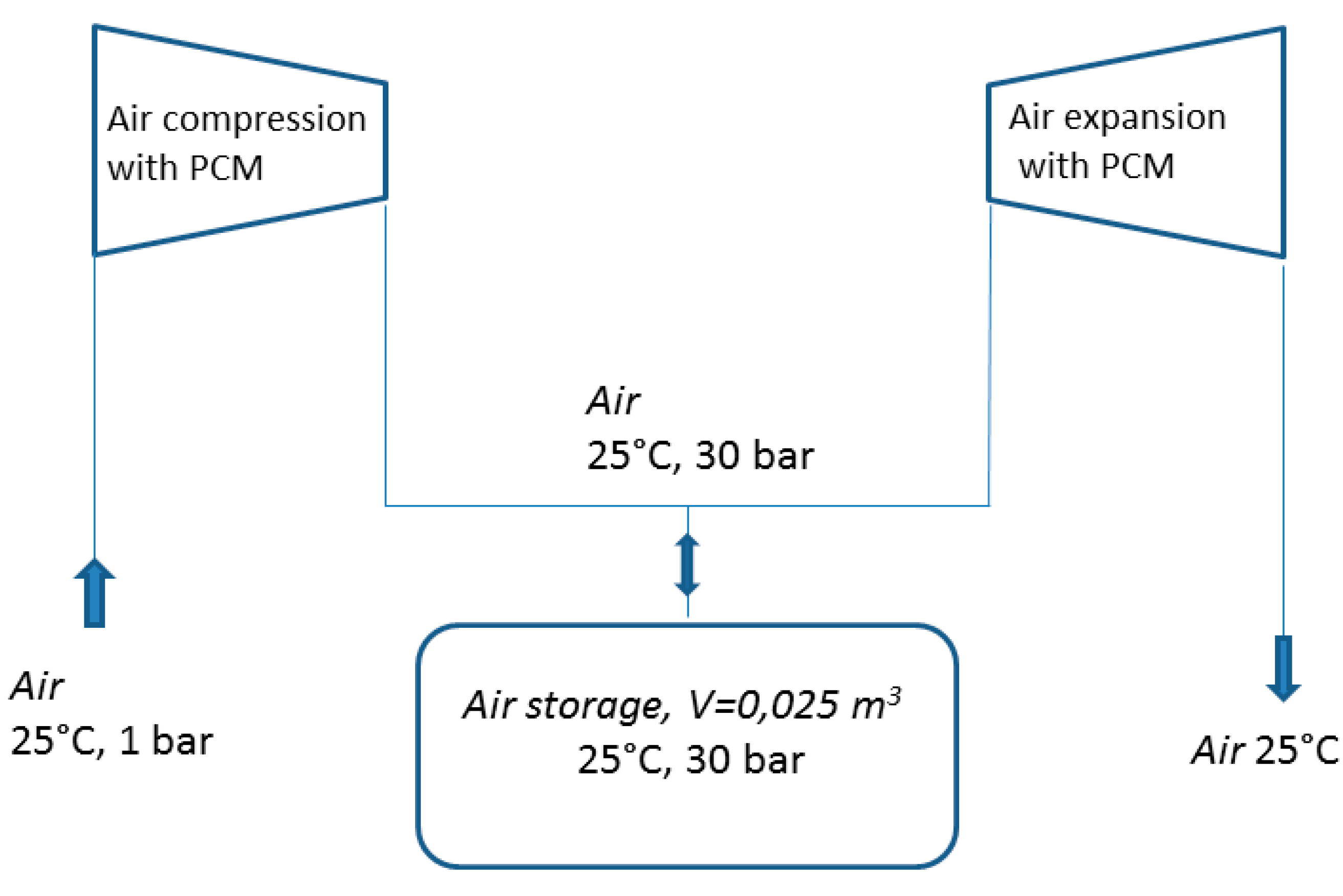
:1. Introduction
2. Experimental Section
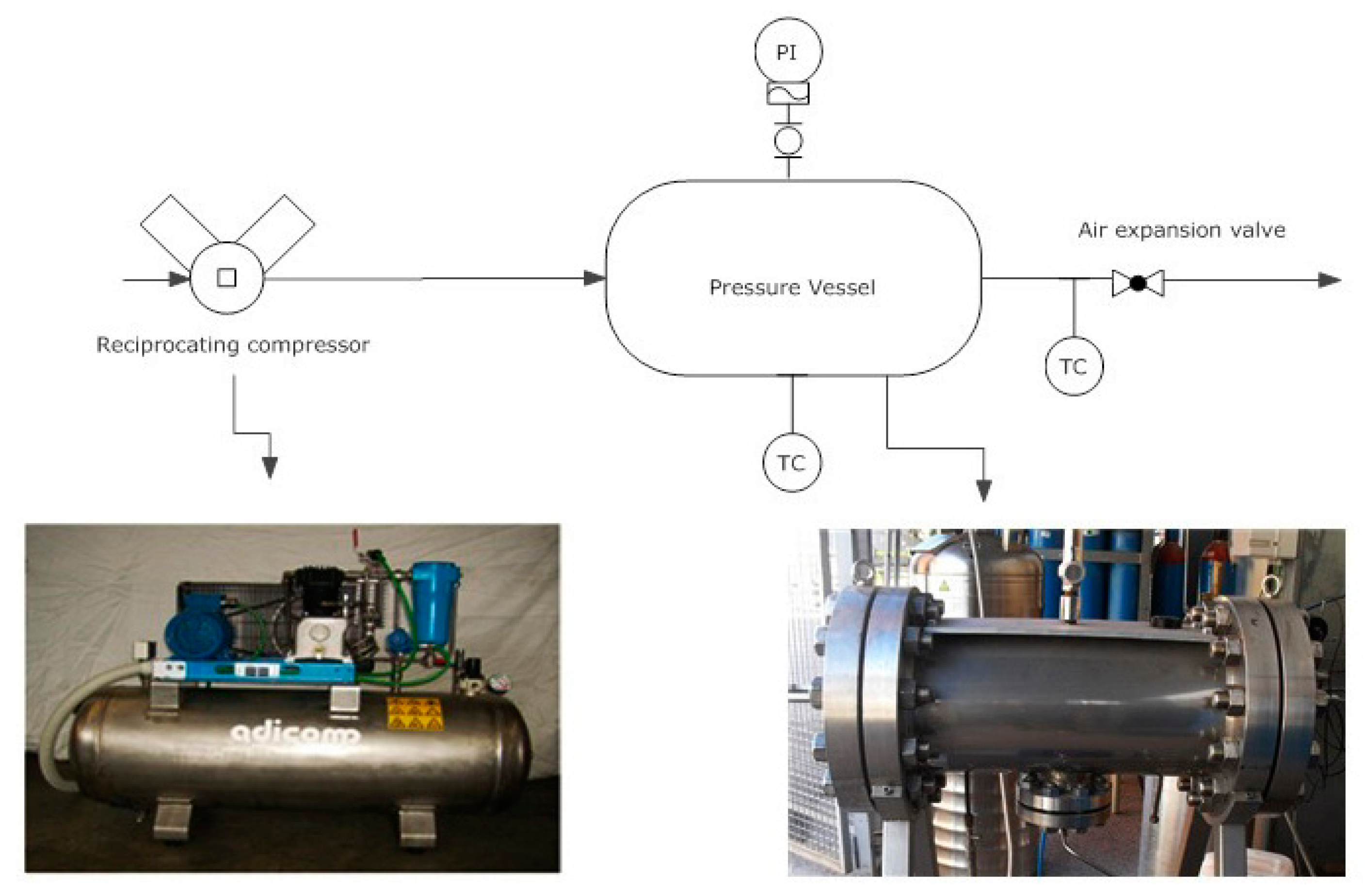
- Air is compressed and uploaded in the vessel. Compression continues until an internal pressure of 20 bar or 30 bar is reached.
- Internal temperature and pressure are adjusted to reach the proper initial conditions
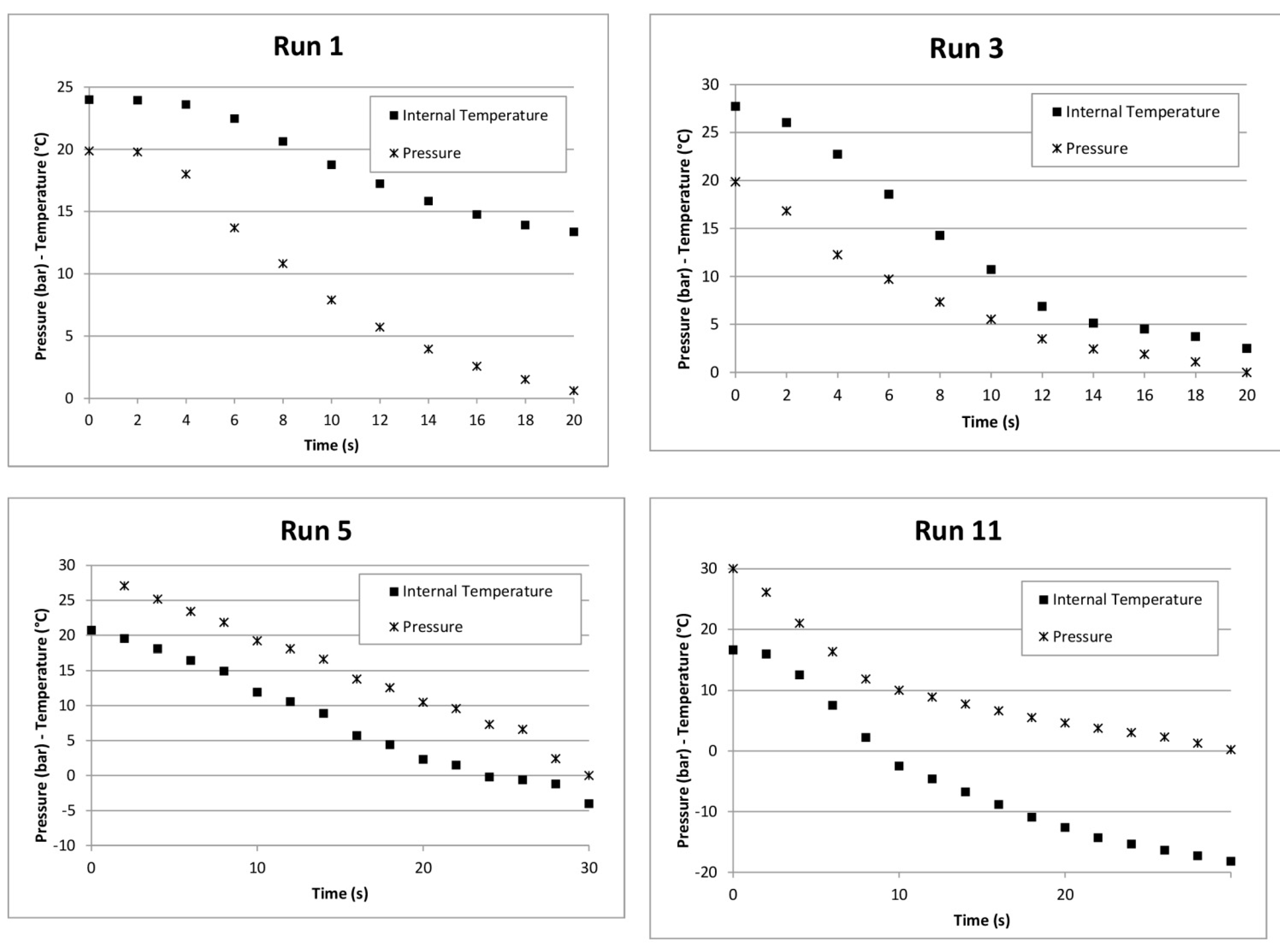
- The outlet port is opened to carry out air expansion. During this phase temperature and pressure are monitored.

| Properties | RT18HC |
|---|---|
| Material | Paraffin |
| Melting Area [°C] | 17–19 |
| Congealing area [°C] | 19–17 |
| Heat storage capacity [kJ/kg] | 250 |
| Specific heat capacity [kJ/kgK] | 2 |
| Density solid [kg/L] | 0.88 |
| Density liquid [kg/L] | 0.77 |
| Heat conductivity [W/mK] | 0.2 |
| Volume expansion [%] | 12 |
Objective of the Experimental Investigation
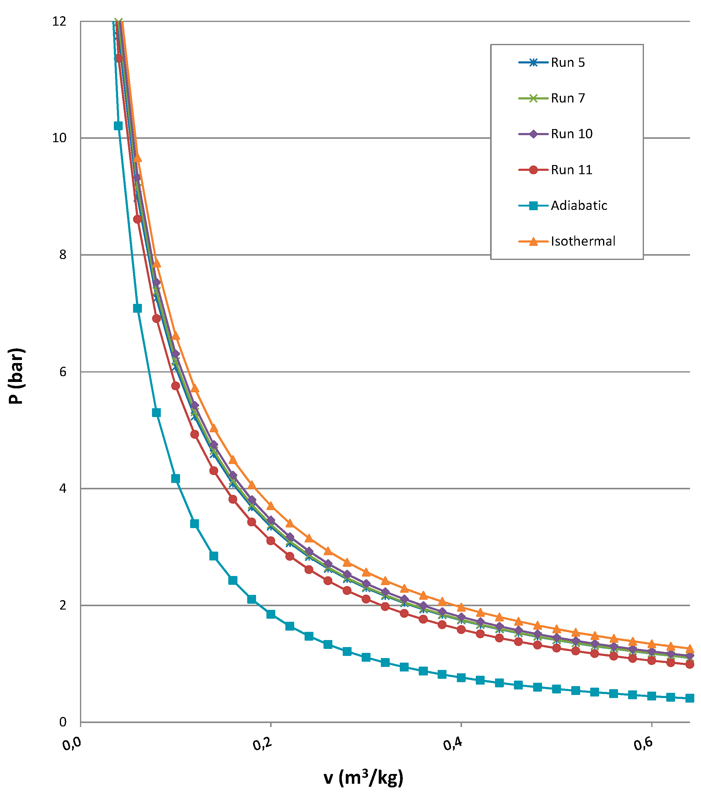
3. Results and Discussion
| Run | Pressure (MPa) | Time (s) | PCM Type | PCM Volume (L) | Initial Temperature (°C) | Final Temperature (°C) | ΔT (°C) |
|---|---|---|---|---|---|---|---|
| 1 | 2 | 20 | RT18HC | 1.12 | 24.0 | 13.0 | 11 |
| 2 | 2 | 20 | RT18HC | 1.12 | 23.7 | 11.0 | 12.7 |
| 3 | 2 | 20 | - | - | 27.7 | 2.5 | 25.2 |
| 4 | 2 | 20 | - | - | 28.4 | 2.9 | 25.5 |
| 5 | 3 | 30 | RT21HC | 1.68 | 20.7 | −4.0 | 24.7 |
| 6 | 3 | 30 | RT21HC | 1.68 | 22.0 | −8.5 | 30.5 |
| 7 | 3 | 30 | RT21HC | 1.12 | 21.9 | −10.2 | 32.1 |
| 8 | 3 | 30 | RT21HC | 1.12 | 19.7 | −12.1 | 31.8 |
| 9 | 3 | 30 | RT21HC | 0.56 | 24.3 | −5.2 | 29.5 |
| 10 | 3 | 30 | RT21HC | 0.56 | 24.5 | −6.0 | 30.5 |
| 11 | 3 | 30 | - | - | 16.6 | −18.2 | 34.8 |
- mPCM is the quantity of PCM necessary for isothermal expansion (kg);
- mair is air inside the vessel at experimental conditions of pressure and temperature (kg);
- cPair is air specific heat capacity (kJ/kgK);
- ΔTair is temperature difference between initial temperature and final temperature (K); and
- CPCM is heat storage capacity (kJ/kg).
| Run 1 | Run 2 | Run 3 | Run 4 | ||||||||||||||||
| T [°C] | P [bar] | v [m3/kg] | T [°C] | P [bar] | v [m3/kg] | T [°C] | P [bar] | v [m3/kg] | T [°C] | P [bar] | v [m3/kg] | ||||||||
| 24.0 | 19.9 | 0.041 | 23.7 | 19.9 | 0.041 | 27.7 | 19.9 | 0.041 | 28.4 | 20.1 | 0.041 | ||||||||
| 23.6 | 18.0 | 0.045 | 22.9 | 17.2 | 0.046 | 26.0 | 16.8 | 0.048 | 27.5 | 18.1 | 0.045 | ||||||||
| 22.5 | 13.7 | 0.057 | 21.4 | 12.9 | 0.061 | 22.7 | 12.3 | 0.063 | 25.3 | 15.4 | 0.052 | ||||||||
| 20.6 | 10.8 | 0.071 | 19.4 | 10.1 | 0.075 | 18.6 | 9.7 | 0.077 | 21.4 | 11.1 | 0.069 | ||||||||
| 18.7 | 7.9 | 0.094 | 17.5 | 7.5 | 0.098 | 14.3 | 7.3 | 0.097 | 16.9 | 8.5 | 0.085 | ||||||||
| 17.2 | 5.7 | 0.124 | 15.9 | 5.3 | 0.131 | 10.7 | 5.5 | 0.122 | 13.0 | 6.4 | 0.107 | ||||||||
| 15.8 | 4.0 | 0.166 | 14.5 | 3.7 | 0.175 | 6.9 | 3.5 | 0.172 | 10.2 | 5.0 | 0.131 | ||||||||
| 14.8 | 2.6 | 0.229 | 13.3 | 2.4 | 0.242 | 5.1 | 2.4 | 0.226 | 8.3 | 4.1 | 0.152 | ||||||||
| 13.9 | 1.5 | 0.329 | 12.4 | 1.5 | 0.328 | 4.5 | 1.9 | 0.264 | 5.5 | 2.3 | 0.233 | ||||||||
| 13.4 | 0.6 | 0.514 | 11.7 | 0.6 | 0.511 | 3.7 | 1.1 | 0.364 | 4.4 | 1.3 | 0.332 | ||||||||
| 13.0 | 0.0 | 0.821 | 11.0 | 0.0 | 0.815 | 2.5 | 0.0 | 0.761 | 2.9 | 0.0 | 0.760 | ||||||||
| Run 5 | Run 6 | Run 7 | Run 8 | ||||||||||||||||
| T [°C] | P [bar] | v [m3/kg] | T [°C] | P [bar] | v [m3/kg] | T [°C] | P [bar] | v [m3/kg] | T [°C] | P [bar] | v [m3/kg] | ||||||||
| 20.7 | 30.3 | 0.027 | 22.0 | 30.0 | 0.027 | 21.9 | 30.0 | 0.027 | 19.7 | 30.0 | 0.027 | ||||||||
| 19.5 | 27.1 | 0.030 | 20.9 | 27.1 | 0.030 | 21.3 | 28.1 | 0.029 | 18.7 | 27.4 | 0.030 | ||||||||
| 18.1 | 25.2 | 0.032 | 19.7 | 25.5 | 0.031 | 20.4 | 26.5 | 0.031 | 16.2 | 24.0 | 0.033 | ||||||||
| 16.5 | 23.4 | 0.034 | 16.9 | 22.6 | 0.035 | 19.3 | 24.9 | 0.032 | 13.3 | 21.3 | 0.037 | ||||||||
| 14.9 | 21.9 | 0.036 | 12.2 | 18.6 | 0.041 | 17.9 | 23.4 | 0.034 | 10.2 | 19.1 | 0.040 | ||||||||
| 11.9 | 19.2 | 0.040 | 10.5 | 17.0 | 0.044 | 16.4 | 22.0 | 0.036 | 7.2 | 16.8 | 0.045 | ||||||||
| 10.6 | 18.1 | 0.042 | 9.8 | 16.3 | 0.046 | 14.9 | 20.8 | 0.038 | 4.5 | 14.6 | 0.051 | ||||||||
| 8.9 | 16.6 | 0.045 | 8.6 | 14.9 | 0.050 | 13.4 | 19.7 | 0.040 | 1.8 | 12.4 | 0.059 | ||||||||
| 5.7 | 13.8 | 0.053 | 7.7 | 13.7 | 0.054 | 12.0 | 18.8 | 0.041 | −0.7 | 10.3 | 0.069 | ||||||||
| 4.4 | 12.5 | 0.058 | 6.3 | 11.8 | 0.061 | 9.1 | 16.3 | 0.047 | −2.9 | 8.4 | 0.083 | ||||||||
| 2.3 | 10.5 | 0.067 | 3.6 | 9.0 | 0.078 | 6.1 | 13.8 | 0.054 | −5.0 | 6.2 | 0.107 | ||||||||
| 1.5 | 9.6 | 0.072 | 2.5 | 8.0 | 0.086 | 3.1 | 11.3 | 0.064 | −6.1 | 5.2 | 0.124 | ||||||||
| −0.2 | 7.3 | 0.092 | 0.4 | 6.1 | 0.108 | 0.3 | 8.8 | 0.080 | −7.2 | 4.1 | 0.150 | ||||||||
| −0.6 | 6.6 | 0.100 | −1.2 | 4.9 | 0.129 | −2.2 | 6.7 | 0.101 | −8.5 | 3.1 | 0.185 | ||||||||
| −1.2 | 2.4 | 0.224 | −4.9 | 2.2 | 0.233 | −5.1 | 4.0 | 0.154 | −9.7 | 2.0 | 0.252 | ||||||||
| −4.0 | 0.0 | 0.751 | −8.5 | 0.0 | 0.730 | −10.2 | 0.0 | 0.756 | −12.1 | 0.0 | 0.750 | ||||||||
| Run 9 | Run 10 | Run 11 | |||||||||||||||||
| T [°C] | P [bar] | v [m3/kg] | T [°C] | P [bar] | v [m3/kg] | T [°C] | P [bar] | v [m3/kg] | |||||||||||
| 24.3 | 29.9 | 0.028 | 24.5 | 30.0 | 0.028 | 16.6 | 30.0 | 0.026 | |||||||||||
| 24.0 | 28.9 | 0.029 | 24.3 | 29.3 | 0.028 | 16.0 | 26.1 | 0.030 | |||||||||||
| 23.1 | 27.1 | 0.030 | 24.0 | 28.3 | 0.029 | 12.5 | 21.0 | 0.037 | |||||||||||
| 20.4 | 22.4 | 0.036 | 22.8 | 26.3 | 0.031 | 7.5 | 16.3 | 0.046 | |||||||||||
| 16.8 | 18.3 | 0.043 | 21.4 | 24.4 | 0.033 | 2.2 | 11.9 | 0.059 | |||||||||||
| 13.0 | 15.3 | 0.050 | 18.8 | 20.6 | 0.039 | −2.5 | 10.0 | 0.068 | |||||||||||
| 9.5 | 12.8 | 0.059 | 15.2 | 16.7 | 0.047 | −4.6 | 8.9 | 0.078 | |||||||||||
| 6.5 | 10.8 | 0.068 | 11.5 | 13.9 | 0.055 | −6.8 | 7.7 | 0.084 | |||||||||||
| 4.2 | 9.1 | 0.079 | 8.1 | 11.6 | 0.064 | −8.8 | 6.6 | 0.100 | |||||||||||
| 2.5 | 7.6 | 0.092 | 5.3 | 9.8 | 0.074 | −10.9 | 5.5 | 0.110 | |||||||||||
| 1.2 | 6.2 | 0.109 | 3.3 | 8.2 | 0.086 | −12.6 | 4.6 | 0.134 | |||||||||||
| 0.3 | 5.1 | 0.129 | 2.3 | 7.2 | 0.096 | −14.3 | 3.7 | 0.149 | |||||||||||
| −0.2 | 4.3 | 0.148 | 0.3 | 5.2 | 0.127 | −15.3 | 3.0 | 0.185 | |||||||||||
| −1.5 | 2.9 | 0.200 | −2.2 | 3.3 | 0.181 | −16.4 | 2.3 | 0.210 | |||||||||||
| −3.0 | 1.7 | 0.287 | −3.3 | 1.8 | 0.277 | −17.3 | 1.3 | 0.319 | |||||||||||
| −5.2 | 0.0 | 0.771 | −6.0 | 0.0 | 0.768 | −18.2 | 0.2 | 0.576 | |||||||||||
| Run 12 | Run 13 | Run 14 | |||||||||||||||||
| T [°C] | P [bar] | v [m3/kg] | T [°C] | P [bar] | v [m3/kg] | T [°C] | P [bar] | v [m3/kg] | |||||||||||
| 16.6 | 30.0 | 0.026 | 24.8 | 30.0 | 0.027 | 23.8 | 30.0 | 0.027 | |||||||||||
| 16.5 | 29.7 | 0.027 | 24.0 | 26.8 | 0.030 | 23.1 | 27.9 | 0.029 | |||||||||||
| 14.7 | 22.2 | 0.035 | 19.7 | 17.7 | 0.044 | 20.0 | 21.0 | 0.038 | |||||||||||
| 9.6 | 15.2 | 0.049 | 13.6 | 12.8 | 0.058 | 14.3 | 13.1 | 0.057 | |||||||||||
| 3.5 | 11.6 | 0.061 | 7.0 | 10.3 | 0.068 | 8.5 | 10.9 | 0.065 | |||||||||||
| −2.5 | 7.9 | 0.084 | 1.5 | 7.5 | 0.088 | 3.5 | 7.0 | 0.094 | |||||||||||
| −7.4 | 5.8 | 0.107 | −2.6 | 5.2 | 0.118 | 0.3 | 5.1 | 0.122 | |||||||||||
| −11.0 | 3.9 | 0.146 | −5.6 | 3.4 | 0.164 | −2.2 | 3.3 | 0.170 | |||||||||||
| −13.4 | 2.3 | 0.214 | −7.5 | 1.9 | 0.247 | −4.0 | 1.8 | 0.259 | |||||||||||
| −14.9 | 1.0 | 0.351 | −8.5 | 0.8 | 0.397 | −5.5 | 0.6 | 0.450 | |||||||||||
| −15.7 | 0.1 | 0.637 | −8.9 | 0.0 | 0.715 | −6.4 | 0.0 | 0.716 | |||||||||||
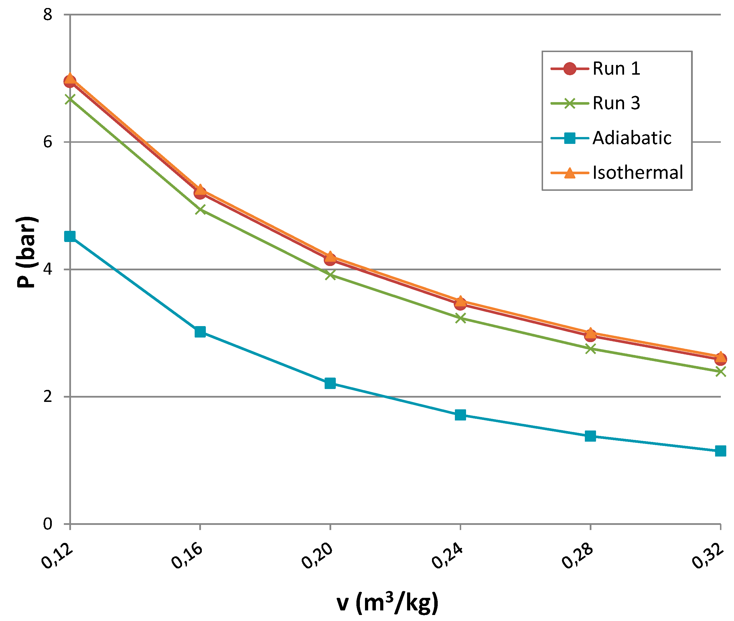
- P is pressure;
- v is the specific volume;
- k is adiabatic constant;
- γ is the adiabatic index calculated as the ratio of the heat capacity at constant pressure to heat capacity at constant volume;
- R is gas constant; and
- T is internal temperature equal to 293 K.

| Pressure 2 MPa and Expansion Time 20 s | ||||||||||||
| Run 1 | Run 2 | Run 3 | Run 4 | Isothermal | ||||||||
| Expansion work (J/kg) | 31.74 | 31.47 | 30.23 | 30.13 | 32.09 | |||||||
| Pressure 3 MPa and Expansion Time 30 s | ||||||||||||
| Run 5 | Run 6 | Run 7 | Run 8 | Run 9 | Run 10 | Run 11 | Isothermal | |||||
| Expansion work (J/kg) | 28.21 | 28.13 | 28.67 | 28.41 | 29.16 | 29.27 | 26.87 | 30.57 | ||||
| Increase in the Expansion Work (%) | |||||||
| Pressure 2 MPa | Pressure 3 MPa | ||||||
| Run 1 | Run 2 | Run 5 | Run 6 | Run 7 | Run 8 | Run 9 | Run 10 |
| 5.4 | 4.5 | 5.0 | 4.7 | 6.7 | 5.7 | 8.5 | 8.9 |
4. Conclusions
Author Contributions
Conflicts of Interest
References
- Kjarstad, J.; Johnsson, F. Fossil Fuels: Climate Change and Security of Supply. Int. J. Sustain. Water Environ. Syst. 2012, 4, 79–87. [Google Scholar]
- Serra, L.M.; Lozano, M.; Ramos, J.; Ensinas, A.V.; Nebra, S.A. Polygeneration and efficient use of natural resources. Energy 2009, 34, 575–586. [Google Scholar] [CrossRef]
- Lund, H.; Salgi, G. The role of compressed air energy storage in future sustainable energy systems. Energy Convers. Manag. 2009, 50, 1172–1179. [Google Scholar] [CrossRef]
- Kim, Y.M.; Favrat, D. Energy and exergy analysis of a micro-compressed air energy storage and air cycle heating and cooling system. Energy 2010, 35, 213–220. [Google Scholar] [CrossRef]
- Ippolito, M.G.; di Silvestre, M.L.; Riva Sanseverino, E.; Zizzo, G.; Graditi, G. Multiobjective optimized management of electrical energy storage systems in an islanded network with renewable energy sources under different design scenarios. Energy 2014, 68, 648–662. [Google Scholar] [CrossRef]
- Rubio-Maya, C.; Uche-Marcuello, J.; Martínez-Gracia, A.; Bayod-Rújula, A. Design optimization of a polygeneration plant fuelled by natural gas and renewable energy sources. Appl. Energy 2011, 88, 449–457. [Google Scholar] [CrossRef]
- International Electrotechnical Commission IEC (Electrical Energy Storage Project Team). Electrical Energy Storage; IEC: Geneva, Switzerland, 2011. [Google Scholar]
- Rossi, F.; Nicolini, A. Experimental Investigation on a Novel Electrolyte Configuration for Cylindrical Molten Carbonate Fuel Cells. J. Fuel Cell Sci. Technol. 2011. [CrossRef]
- Rossi, F.; Nicolini, A. A Cylindrical Small Size Molten Carbonate Fuel Cell: Experimental Investigation on Materials and Improving Performance Solutions. Fuel Cells 2009, 9, 170–177. [Google Scholar] [CrossRef]
- Cotana, F.; Filipponi, M.; Castellani, B. A Cylindrical Molten Carbonate Fuel Cell Supplied with Landfill Biogas. Appl. Mech. Mater. 2013, 392, 512–516. [Google Scholar] [CrossRef]
- Castellani, B.; Giuliobello, M.; Morini, E.; Filipponi, M.; Nicolini, A.; di Giovanna, L.; Cotana, F.; Rossi, F. Methane production as solar energy storage: Energy and process evaluations. In Proceedings of the 14th CIRIAF National Congress, Energy, Environment and Sustainable Development, Perugia, Italy, 4–5 April 2014.
- Castellani, B.; Morini, E.; Filipponi, M.; Nicolini, A.; Palombo, M.; Cotana, F.; Rossi, F. Clathrate Hydrates for Thermal Energy Storage in Buildings: Overview of Proper Hydrate-Forming Compounds. Sustainability 2014, 6, 6815–6829. [Google Scholar] [CrossRef]
- Castellani, B.; Rossi, F.; Filipponi, M.; Nicolini, A. Hydrate-based removal of carbon dioxide and hydrogen sulphide from biogas mixtures: Experimental investigation and energy evaluations. Biomass Bioenergy 2014, 70, 330–338. [Google Scholar] [CrossRef]
- Brinchi, L.; Castellani, B.; Rossi, F.; Cotana, F.; Morini, E.; Nicolini, A.; Filipponi, M. Experimental investigations on scaled-up methane hydrate production with surfactant promotion: energy considerations. J. Pet. Sci. Eng. 2014, 120, 187–193. [Google Scholar]
- International Energy Agency (IEA). Technology Roadmap: Energy Storage; IEA: Paris, France, 2014. [Google Scholar]
- Radgen, P. 30 Years Compressed Air Energy Storage Plant Huntorf—Experiences and Outlook. In Proceedings of the 3rd International Renewable Energy Storage Conference, Berlin, Germany, 24–25 November 2008.
- Succar, S.; Williams, R.H. Compressed Air Energy Storage: Theory, Resources, and Applications for Wind Power; Technical Report; Princeton University: Princeton, NJ, USA, 2008. [Google Scholar]
- Bullough, C. Advanced Adiabatic Compressed Air Energy Storage for the Integration of Wind Energy. In Proceedings of the European Wind Energy Conference and Exhibition, London, UK, 22–25 November 2004.
- RWE. ADELE—Adiabatic compressed-air energy storage (CAES) for electricity supply. Available online: http://www.rwe.com (accessed on 14 March 2015).
- Sustainx. Isothermal CAES Technology. Available online: http://www.sustainx.com/technology-isothermal-caes.htm (accessed on 14 March 2015).
- Kim, Y.M.; Lee, J.H.; Kim, S.J.; Favrat, D. Potential and Evolution of Compressed Air Energy Storage: Energy and Exergy Analyses. Entropy 2012, 14, 1501–1521. [Google Scholar] [CrossRef]
© 2015 by the authors; licensee MDPI, Basel, Switzerland. This article is an open access article distributed under the terms and conditions of the Creative Commons Attribution license (http://creativecommons.org/licenses/by/4.0/).
Share and Cite
Castellani, B.; Presciutti, A.; Filipponi, M.; Nicolini, A.; Rossi, F. Experimental Investigation on the Effect of Phase Change Materials on Compressed Air Expansion in CAES Plants. Sustainability 2015, 7, 9773-9786. https://doi.org/10.3390/su7089773
Castellani B, Presciutti A, Filipponi M, Nicolini A, Rossi F. Experimental Investigation on the Effect of Phase Change Materials on Compressed Air Expansion in CAES Plants. Sustainability. 2015; 7(8):9773-9786. https://doi.org/10.3390/su7089773
Chicago/Turabian StyleCastellani, Beatrice, Andrea Presciutti, Mirko Filipponi, Andrea Nicolini, and Federico Rossi. 2015. "Experimental Investigation on the Effect of Phase Change Materials on Compressed Air Expansion in CAES Plants" Sustainability 7, no. 8: 9773-9786. https://doi.org/10.3390/su7089773
APA StyleCastellani, B., Presciutti, A., Filipponi, M., Nicolini, A., & Rossi, F. (2015). Experimental Investigation on the Effect of Phase Change Materials on Compressed Air Expansion in CAES Plants. Sustainability, 7(8), 9773-9786. https://doi.org/10.3390/su7089773