Abstract
The temperature response in the soil surrounding multiple boreholes is evaluated analytically and numerically. The assumption of constant heat flux along the borehole wall is examined by coupling the problem to the heat transfer problem inside the borehole and presenting a model with variable heat flux along the borehole length. In the analytical approach, a line source of heat with a finite length is used to model the conduction of heat in the soil surrounding the boreholes. In the numerical method, a finite volume method in a three dimensional meshed domain is used. In order to determine the heat flux boundary condition, the analytical quasi-three-dimensional solution to the heat transfer problem of the U-tube configuration inside the borehole is used. This solution takes into account the variation in heating strength along the borehole length due to the temperature variation of the fluid running in the U-tube. Thus, critical depths at which thermal interaction occurs can be determined. Finally, in order to examine the validity of the numerical method, a comparison is made with the results of line source method.
1. Introduction
Geothermal energy systems are increasingly utilized recently, but questions exist regarding the sustainability and impact of these systems on the environment [1,2,3]. The use of geothermal energy is often beneficial, especially due to its efficiency. Little research is available to help regulatory agencies and industry develop designs and installations that have good sustainability aspects. One potential factor that detracts from the sustainability of these systems at their design efficiency is the system thermal loss, which can interact with adjacent systems and the surrounding ground [4]. Interference effects are present in some installed geothermal systems, suggesting that these systems may have a spacing below the threshold spacing for such systems to avoid thermal interactions. Thus, there may be a limit to the density of geothermal development in a given region.
Many geothermal energy studies have focused on modeling single ground boreholes, usually based on analytical [5,6,7,8,9,10,11,12,13,14,15,16,17,18,19,20,21] and numerical approaches [22,23,24,25,26,27,28,29,30,31,32]. The models vary in regarding how (1) heat conduction in the soil is solved and (2) heat transfer outside of the boreholes is coupled to the heat transfer inside of the borehole, and (3) the numerical methods are accelerated. The performance of borehole heat exchangers (BHEs) has been simulated with a three-dimensional finite-difference method in rectangular coordinates [29]. Each borehole is approximated by a square column to avoid using fine grids inside the borehole, and heat transfer in the borehole is evaluated for quasi-steady state conditions, allowing variable temperature and loading along the borehole. A three-dimensional unstructured finite-volume numerical model is proposed of a vertical U-tube ground heat exchanger (GHE) [30]. The soil is divided into layers in the axial direction to account for axial temperature variations. A three-dimensional numerical model that simulates fluid transport in a pipe loop and heat transfer with the ground has been developed to address the effect of the thermal mass of the circulating fluid and the dynamics of fluid transport through the loop [31].
An important limitation in most previous reports is the assumption of constant and uniform heat input from the borehole into the ground, whether the borehole is assumed cylindrical or a line source of heat. Transient heat conduction from a buried power transmission line tower has been investigated by formulating the problem of ground heat transfer with a line source of heat with varying heating strength along its length [33,34]. However, that problem involves conduction along a buried rod in the ground which differentiates it somewhat from borehole analysis. Madani et al. [35] evaluate the effect of mass flow rate of the fluid running in the borehole heat exchanger on pumping power, efficiency of the pump, heat distribution in the borehole, heat pump heat capacity and overall coefficient of performance. They present measured temperatures and calculated specific heat extracted along the U-pipes for seven sections along the borehole. They show that the temperature rise (in case of heat extraction) along the U-pipes becomes weaker as the fluid travels between the inlet and outlet pipes. Acuna et al. [36] propose a Distributed Thermal Response Test by measuring temperatures at different depths along the borehole while running the conventional thermal response test and showing local variations of the ground thermal conductivity and borehole thermal resistance along the borehole. Marcotte and Pasquier [37] use a 3D finite element model of the borehole to show that the average of inlet and outlet fluid temperatures in the borehole that is used to estimate the thermal parameters in the interpretation of in situ thermal response tests is only valid for the unrealistic assumption of constant heat flux along the borehole and does not correspond to the fluid mean temperature within the borehole. Using the simulation results, they propose a new estimator that closely fits the average fluid temperature. Another key limitation of past studies is that the potential existence of thermal interaction among multiple boreholes, although identified, is not formulated, and the relevant parameters have not been assessed.
To model interacting borehole systems, Koohi-Fayegh and Rosen [38] evaluate numerically the temperature response in the soil surrounding multiple boreholes in a study, assuming the heat flux from the borehole wall is constant and, therefore, that heat conduction in the direction of the borehole length is negligible for a major part of the solution domain. Also, Koohi-Fayegh and Rosen perform analytical and numerical analysis to study the thermal interaction among boreholes with varying heat input into the ground, to extend prior work [39,40]. The analytical quasi-three-dimensional solution to the heat transfer problem of the U-tube configuration inside the borehole is used to determine the heat flux from the borehole wall [5], showing that thermal interaction at the top of the boreholes is at its highest value due to the higher heating strength at this depth. The current study validates and compares the two approaches in terms of the soil temperature rise and the borehole wall heat flux [39,40].
2. Methods
To examine the existence of thermal interaction among multiple boreholes and their possible negative effects on the design performance of the existing nearby boreholes, the transient conduction of heat in the soil surrounding these systems needs to be studied in order to evaluate the temperature rise and the heat flows in the soil surrounding the boreholes. Representation of heat flows to and from the system based in this simulation can serve as inputs into large scale ground water models.
2.1. Inside Borehole: Variable Heat Flux Model
The authors used a quasi-three-dimensional model proposed by Zeng et al. [5,41] in order to derive the heat flux distribution along the borehole depth [39,40]. The heat flow rate per unit length of the borehole (q') transferred to the soil, calculated from the temperature difference between the borehole wall and the fluid in each of the tubes in the borehole, can be obtained from

where Tf1, Tf2 and Tb are the temperatures of the fluid running downwards, the fluid running upwards and borehole wall, respectively, and

Here, R11 and R22 are the thermal resistance between the circulating fluid and the borehole wall, and R12 is the resistance between the tubes (Figure 1) obtained from the relations derived by detail by Hellström [9]. For different numbers of pipes in any position in the borehole, Claesson and Hellström [10] present a method to calculate the thermal resistances between the heat carrier fluid in the pipes of the borehole and the immediate vicinity of the surrounding ground. In most engineering applications, the configuration of the U-tube in the borehole may be assumed symmetric, and here it is assumed that the thermal resistance between the circulating fluid in each of the tubes and the borehole wall is equal.
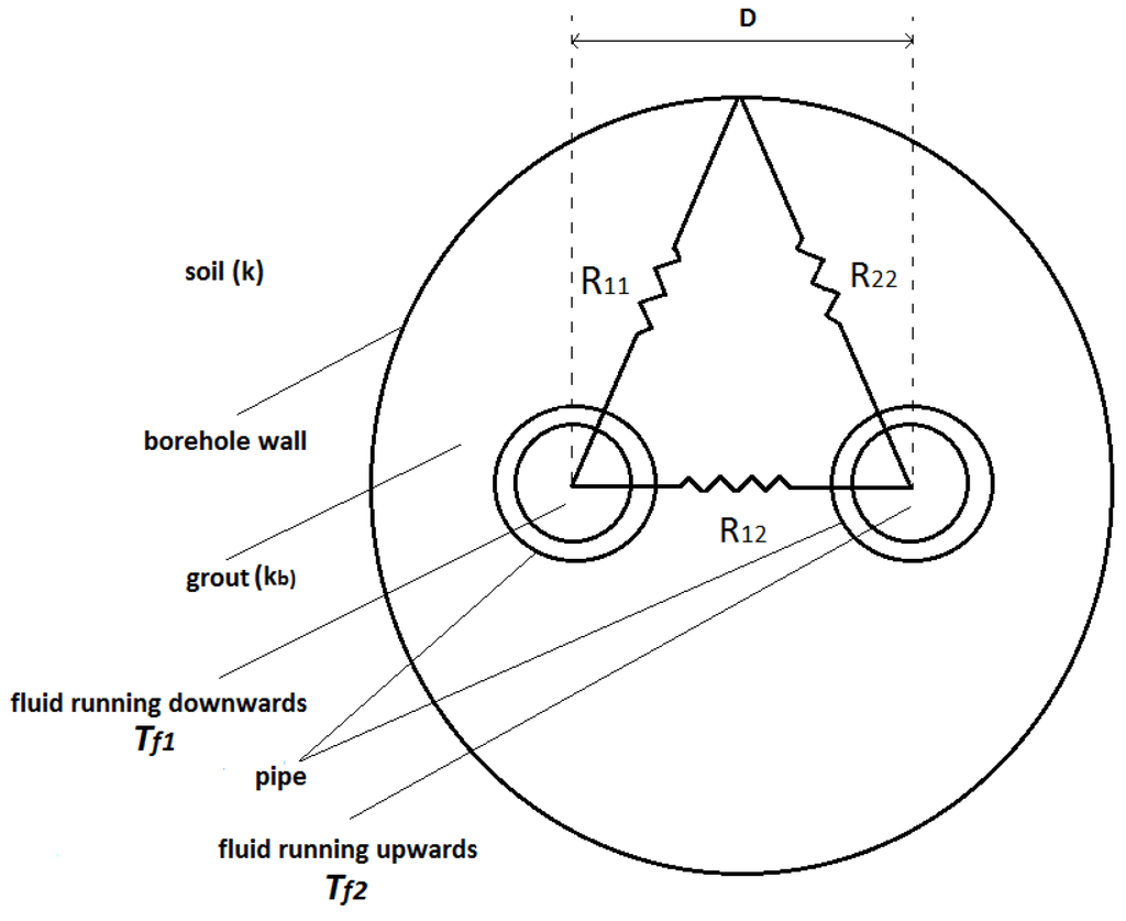
Figure 1.
Thermal resistances in the borehole.
The heat flow rate per unit length of the borehole can be formulated [39,40] as

where the dimensionless parameters are defined as

where Tf' is the temperature of the fluid entering the U-tube. The temperature profiles of the fluids flowing in the U-tubes in the boreholes (Θ1(Z) and Θ2(Z)) are formulated by Zeng et al. [5].
Assuming that the heat is dissipated symmetrically in the soil around each borehole, Equation (3) can be written in the following form:

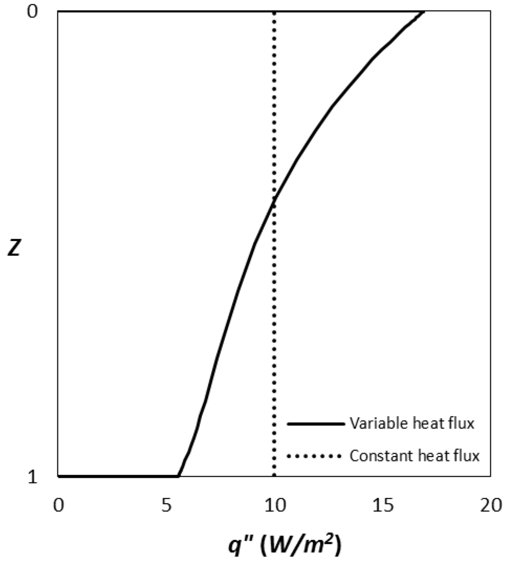
Figure 2.
Distribution of heat flux along the borehole length.
This is the spatial distribution of the heating strength along the rod. In contrast to past studies, this heating strength varies along the rod and is not constant (Figure 2). Note that the variable heat source (VHS) model has made certain simplifying assumptions, such as constant ground temperature.
In order to compare the results gained by constant heat flux model with the results gained by the VHS model, an equivalent inlet temperature (Tf'= 290.6 K) for the VHS model, resulting in the same total heat conduction in the soil, is assumed.
2.2 Outside Borehole
A three-dimensional model of transient conduction of heat in the soil around multiple ground heat exchangers is presented in this section. A domain consisting of two vertical borehole heat exchangers having a distance of 2h from each other is considered (Figure 3).
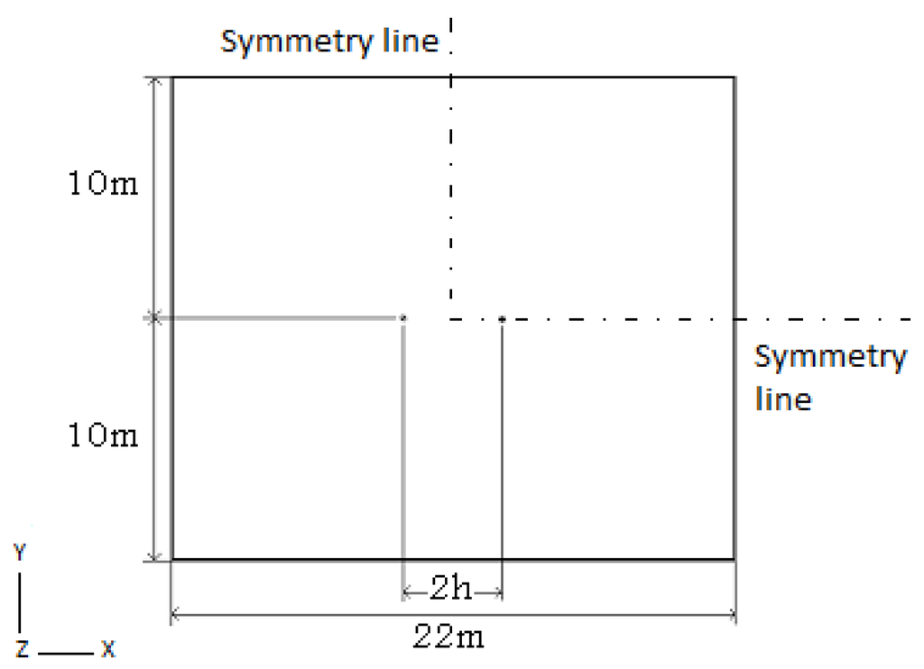
Figure 3.
Horizontal cross sections (xy) of the solution domain at the borehole mid-length (z = 0 m).
It is assumed that the dominant mode of heat transfer in the soil is conduction. The general heat conduction equation in cylindrical coordinates appears in the following form:

where t is the time from the start of operation, α is the thermal diffusivity of soil, and T is the temperature of the ground. The first two terms on the left side of Equation (6) are the heat flux components in the radial (r) direction, the third and the fourth terms are related to the circumferential (φ) and axial (z) directions, respectively, and the fifth term relates to the heat generated in the control volume. The right side of Equation (6) represents the transient effects of heat conduction. In the analysis, an analytical and a numerical approach are used to calculate the temperature profiles of the soil around the boreholes.
2.2.1. Analytical Approach
The model of Zeng et al. [16] establishes the transient response at any point in the ground, subject to a constant line heat source in the rod. However, the previous analysis has shown that the heating strength varies with depth. Thus, the model by Zeng et al. [16] model can be extended to this case by integrating the heating strength over the depth of the rod. The temperature response at any point in the semi-infinite medium will be calculated for a point, P(q,z), in the medium. Duan et al. [33] and Duan and Naterer [34] extended Zeng et al.’s model [16] for the case of a buried rod. They formulated the temperature profile in the soil around the rod. Based on their study, it can be shown that

where  ,
,  ,
,  ,
,  and
and  is the heating strength per unit length which varies along the borehole depth.
 ,
,  ,
,  ,
,  and
and  is the heating strength per unit length which varies along the borehole depth.
Using this procedure for the case of a vertical borehole containing U-tube with running fluid, the heating strength formulated for the case of variable heating strength (Equation (3)) is substituted in Equation (7) to obtain the temperature rise in the soil surrounding a borehole.
For the case of multiple boreholes, since the conduction equation is linear, the temperature response in the soil can be calculated by superposing the temperature rise in the soil caused by each single borehole. Koohi-Fayegh and Rosen [38] examine the validity of superposition method in thermal response in the soil surrounding multiple boreholes by comparing the superposition results of the line source theory with results obtained by a finite volume numerical method. It was shown that the results of the two methods agree well and the effect of the temperature rise due to one borehole on the thermal performance of other boreholes can be neglected. Therefore, the temperature response in the soil surrounding a borehole system of n boreholes can be calculated by superposing the temperature response evaluated by each borehole in Equation (7):

where  is the heat flow rate per unit length of Borehole i (Figure 4), n is the number of boreholes and
 is the heat flow rate per unit length of Borehole i (Figure 4), n is the number of boreholes and
where li and wi are distances of boreholes i along x and y directions, respectively. For the case of multiple boreholes shown in Figure (4), Equation (8) can be simplified to:

where, as seen in Figure 4,

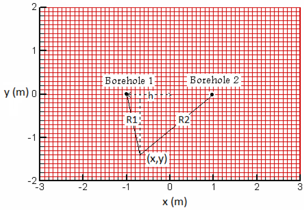
Figure 4.
System geometric parameters for two boreholes at distances R1 and R2 from a desired point (x,y) in the surrounding soil.
2.2.2. Numerical Approach
In the numerical approach, the transient governing integral equations for the conservation of energy is solved with a control volume method in FLUENT. Unlike many of the studies on the heat transfer around multiple boreholes, the current three-dimensional numerical solution takes into account the temperature gradients in the direction adjacent to the borehole length corresponding to the axial heat transfer effects in the soil. The heat transfer symmetry about the two vertical planes shown in Figure 3 is utilized. Therefore, only one fourth of the borehole field is modelled and the solution domain (soil) is enclosed by the far-field, the ground surface and two symmetry planes. In Figure 5, the gray area is the solution domain, the results of which can be replicated to the other areas drawn with dashed lines due to their symmetry.
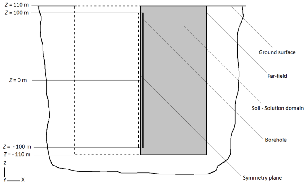
Figure 5.
Vertical cross section (xz) of the solution domain.
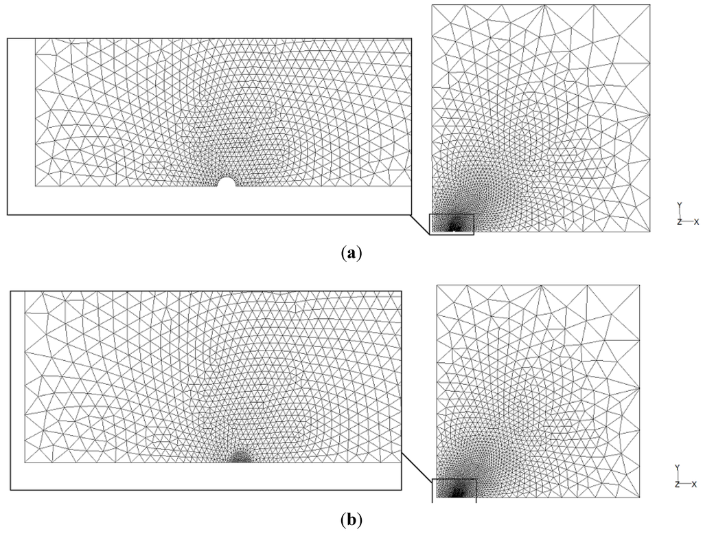
Figure 6.
Simulation model for horizontal cross sections (xy) at (a) borehole mid-length (z = 0 m), and (b) the ground surface (z = 110 m).
A control-volume-based technique is used that divides the domain into discrete control volumes using unstructured computational triangular grids, as shown in Figure 6. The temperature gradient in the domain between the borehole wall and the far-field changes gradually from large to small ones. Therefore, to reduce computer memory and computational time, the size of the mesh cells is chosen based on this gradual change. Figure 6(a,b) refer to two xy cross sections shown in Figure 5 to show the mesh in the cross sections containing the borehole and above or below it. The vertical section domain may be discretized using structured grids due to relatively simple geometric structure, as shown in Figure 7.
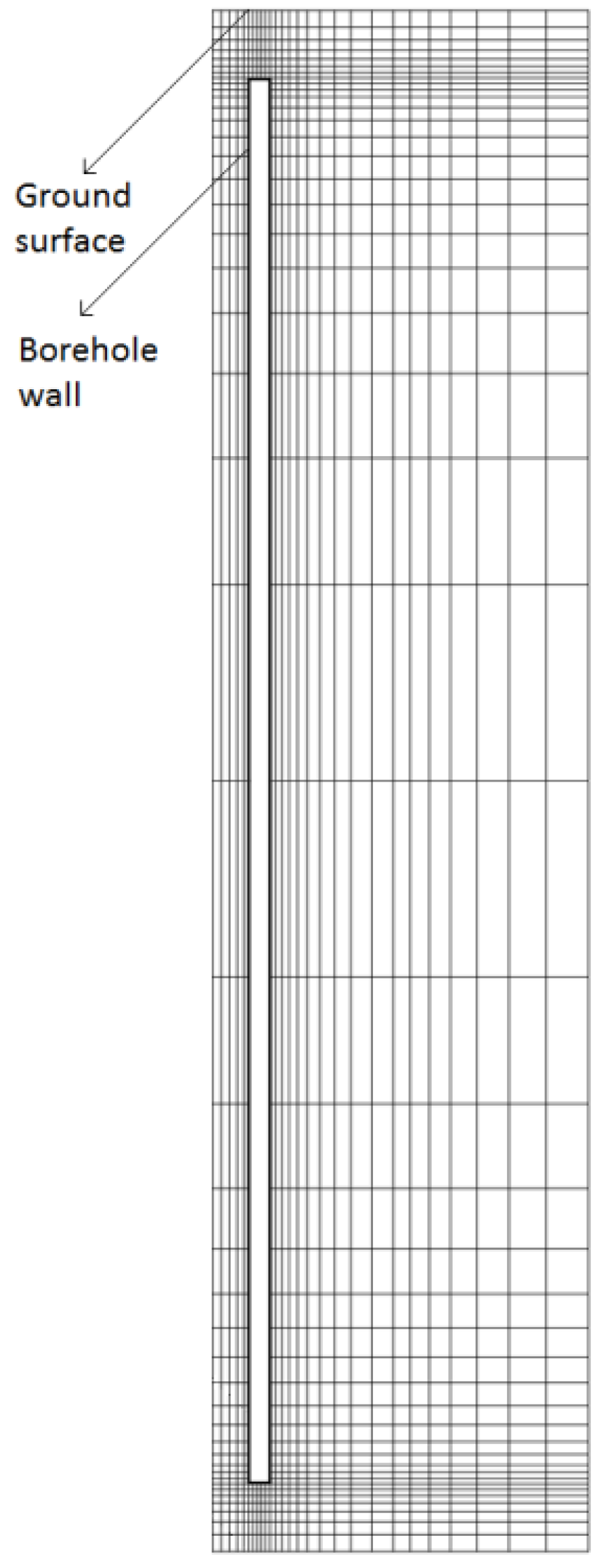
Figure 7.
Simulation model for multiple boreholes in vertical cross section (xz).
The discretization in unstructured meshes can be developed from the basic control volume technique where the integral form of the energy conservation equation is used as the starting point:

Here, ΔV is the volume. Integration of Equation (12) over a time interval from t to t + Δt gives:

Using a fully implicit formulation, Equation (13) is discretized in the following form:

where ap, ap0 and anb are temperature coefficients which are calculated based on the geometric characteristics of each control volume and the time step in the numerical solution.
Equation (14) is solved iteratively at each time level before moving to the next time step to yield updated values of temperature.
The purpose of performing the numerical simulation is to gain a degree of confidence in the analytical solution. In order to prevent the errors associated with the quassi-three-dimensional solution, the solution to this model is used in the numerical solution as a boundary condition. Thus, any difference between soil temperature profiles of analytical and numerical solutions would be caused by the used superposition method and the line source theory. A future extension to the current study is planned to compare the numerical method with the analytical one including the numerical solution of the inside of the borehole as well.
2.2.3. Initial and Boundary Conditions
A uniform initial temperature of 288 K (equal to the undisturbed ground temperature) is assumed to be effective over the entire borefield. The ground surface is assumed to be isothermal and equal to the ground initial temperature. At the outer edge of the domain, a constant far-field temperature condition equal to the initial temperature is applied (288 K) in the numerical solution. The temperature and heat flux distributions on the borehole wall cannot be decided due to the dynamic nature of the heat exchange process between the tubes in the borehole and the borehole wall. However, to simplify the current model, a constant heat flux of 10 W/m2 on the borehole wall can be assumed since in order to study the thermal interaction between multiple boreholes, their inner dynamic heat exchange process can be of second priority compared to the heat dissipation in the soil surrounding them. As a second approach, a variable heat flux (VHF) along the borehole is calculated by defining the temperature profiles of the fluid running along the tubes in the borehole. It should be noted that the current article focuses only on the variation of heating strength along the borehole length. Since only the existence of such a variation is intended to be discussed, the current article does not provide typical values for the borehole spacing and the heat flux on the borehole wall and lower values are chosen in order to keep the solution domain size smaller in the numerical solution. It should also be noted that the temperature of the soil in the current problem is assumed to be constant throughout the whole operation time and therefore the current solution is only valid for low temperature variations in the soil surrounding the boreholes which is only gained by assuming lower heat flux values on the borehole wall. Modifying the current problem to one with typical industrial values for ground heat pump systems will need the soil temperature to be assumed variable and is subject of ongoing research by the authors.
In order to account for the transient term in Equation (6), the time is subdivided into 4200 time steps of 3600 s which equals a time period of 6 months.
3. Results and Discussion
In the current study, typical geometrical and thermal characteristics for the borehole and the surrounding soil are assumed (Table 1). Note that the properties of soil are approximate values for dry clay.
The temperature responses of the soil around multiple boreholes evaluated by the VHF model at various borehole depths are compared in Figure 8 and Figure 9a. It is shown in Figure 8 that the maximum temperature rise due to thermal interaction of multiple boreholes in a six-month period of heat transfer from the borehole into the soil occurs at the top 3% heating length of the borehole and it decreases along the borehole length as the heat flux from the borehole wall into the soil decreases. Therefore, with the objective of limiting boreholes’ operations and sizes in order to prevent their thermal interaction, the top length of the boreholes (about 3% total length) is the critical area. Also, as expected the maximum temperature rise in the soil occurs at the borehole wall (x = 0.95 m and x = 1.05 m). Since the current study is not using typical conditions such as typical values for borehole spacing, heat flux on the borehole wall, etc., a minimum value of spacing is not suggested in this study. An extension of the current study to typical industrial values may require the assumptions of constant borehole wall temperature and constant ground surface temperature made in the current model to be modified to be variable and is subject of ongoing research by the authors. In such a case, using the current solution method, it is possible to gain a minimum value of spacing or maximum amount of heat input to the ground to avoid thermal interactions between boreholes under typical conditions.

Table 1.
Parameters of the reference borehole.
| (a) Inside the borehole (U-tube and grout region). | |||||||
| H(m) | rb(m) | rp(m) | D(m) | Db(m) | kb(W/mK) |  (kg/s) (kg/s) | c(J/kgK) |
| 200 | 0.05 | 0.02 | 0.02 | 2 | 1 | 0.2 | 4187 |
| (b) Outside the borehole (soil region). | |||||||
| k(W/mK) | c(J/kgK) | ρ (kg/m3) | |||||
| 1.5 | 1381 | 1200 | |||||
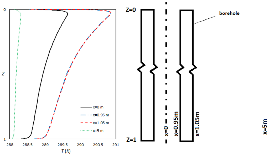
Figure 8.
Soil temperature (K) around multiple boreholes in xz plane in t = 6 months, at various distances from borehole wall for variable heat flux (VHF) model.
It is shown in Figure 9a that the thermal interaction between the boreholes is at its minimum at the bottom of the borehole (z = −99.9 m) where the heat flux to the soil is lowest. This is not true for the case of constant heat flux from the borehole wall to the surrounding soil along the borehole length (Figure 9b). It is seen in Figure 9b that the greatest thermal interaction occurs at top of the borehole, but remains at its maximum amount along the borehole length. For this case, the critical length of the borehole would be almost 95% of the borehole length. However, as discussed earlier, the case of constant heat flux is only a simplification to the VHF problem and does not present the problem as accurate as the VHF problem.
Another notable characteristic of Figure 9a and Figure 9b is the decrease in the thermal interaction in the lengths of z = 99.9 m when one moves from z = 95 m towards the top end of the borehole. Specifically for the case of VHF (Figure 9a), there is higher heat flux as one moves towards the top end and one expects greater thermal interactions. In both cases, the temperature rise in the soil around the borehole declines at the very end of borehole length, and this can be due to axial heat transfer effects which become notable only at the very ends of borehole lengths.
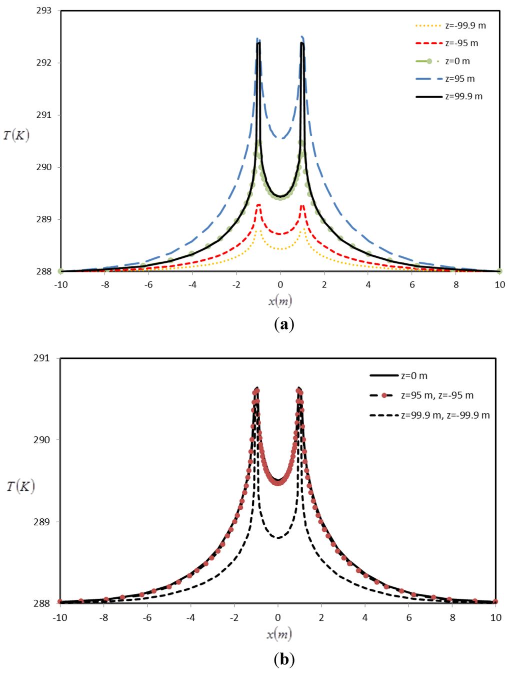
Figure 9.
Soil temperature (K) around multiple boreholes in t = 6 months, at various borehole depths for (a) VHF model, and (b) constant heat flux model.
The results of the VHF model and constant heat flux model are compared in Figure 10. It is seen in Figure 10a that the assumption of constant heat flux on the borehole wall introduces numerous inaccuracies especially when dealing with the temperature rises in the soil at the very top and bottom of the borehole. Figure 10b shows that, by using varying heat flux method, the heat flux on the borehole is spread along the borehole in a way that the middle area remains similar to its average amount. It can be concluded that using the constant heat flux method is only valid for the middle length of the boreholes and moving any further to the top or bottom of the borehole, the temperature rises evaluated become increasingly inaccurate. Quasi-three-dimensional models reveal drawbacks of two-dimensional models and are thus preferred for design and analysis of ground heat exchangers, as they provide more accurate information for performance simulation, analysis and design.
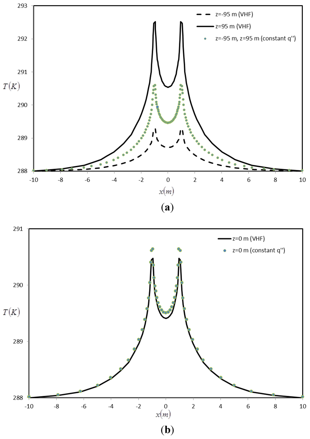
Figure 10.
Comparison of soil temperature (K) around multiple boreholes at t = 6 months for VHF and constant heat flux models, at (a) z = 95 m and z = −95 m, and (b) z = 0 m.
It should be noted that the effect of temperature rise due to one borehole on the other is neglected by applying the superposition method. This effect has been examined for a two-dimensional numerical study by Koohi-Fayegh and Rosen [38]. A comparison of the results of the numerical solution with analytical results of line source theory where the superposition method is used to account for the temperature rise in the soil surrounding multiple boreholes shows that these effects are minor in comparison to the order of the temperature rise in the soil due to the individual performance of the boreholes. Since the objective in the current study is to examine at what depths the thermal interaction among boreholes creates a critical temperature rise, the focus is mostly on introducing a heat flow rate profile along the borehole length which can be coupled to the numerical or line source model outside the borehole to show the effect of varying heat flux along borehole length on temperature rise in the soil. In Figure 11, comparison is made between the two methods and it is shown that the temperature rise in the soil caused by both methods agree well. Therefore, it can be concluded that for such problems where the heat input into the ground does not vary with time, the analytical method presented in this paper can present as accurate results as a numerical method.
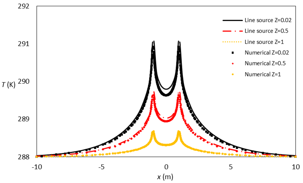
Figure 11.
Soil temperature (K) around multiple boreholes in t = 6 months for line source and numerical models at various borehole depths.
Extension of results to systems of boreholes: The idea of using line source theory for calculating the temperature profiles in the soil around two boreholes can also be applied to two systems of vertical GHEs. For example, if an area of 40 m × 40 m × 200 m in the soil is occupied for one system of vertical GHEs, the ratio of system depth to its initial size is large enough to be accounted as one cylinder or line source of heat when system interactions and temperature excess around a system with larger distances are to be accounted for. The study of variable heating strength along the borehole length also accounts for the system of boreholes as well. Therefore, the parametric study on two interacting boreholes likely exhibits the same affecting parameters and results as those for two interacting systems of boreholes. However, a more detailed comparison of the results of modeling the two systems must be performed in order to show similarities between the two problems. Furthermore, certain assumptions such as the assumption of constant ground temperature as well as constant ground surface temperature must be examined further in order to improve the accuracy of the proposed method.
4. Conclusions
The performance of multiple boreholes or neighbouring borehole systems and their possible thermal interactions are discussed via analytical and numerical methods. The effect of spatial variation of borehole heat flux on the transient response of multiple ground heat exchangers and their thermal interaction is described. A quasi-three-dimensional model for heat transfer inside the borehole is utilised as the boundary condition for the three-dimensional transient heat transfer analysis outside the borehole in order to evaluate the temperature rise in the soil surrounding multiple boreholes and their interaction. It is shown that the maximum temperature rise due to thermal interaction of multiple boreholes in a six-month period of heat transfer from the borehole into the soil occurs right after the beginning of the borehole (about 3% total length) and it decreases along the borehole length as the heat flux from the borehole wall into the soil decreases. Therefore, with the objective of limiting boreholes’ operations and sizes in order to prevent their thermal interaction, the top length of the boreholes is the critical area. It can be concluded that using the constant heat flux method is only valid for the middle length of the boreholes and moving any further to the top or bottom of the borehole, the temperature rise evaluations become increasingly inaccurate. Furthermore, a comparison between the results of line source method and numerical finite volume method shows that the temperature rise in the soil caused by both methods agree well. Therefore, it can be concluded that for such problems where the heat input into the ground does not vary with time, the analytical method presented in this paper can result in as accurate results as a numerical method.
Nomenclature
| a | temperature coefficient |
| cp | specific heat at constant pressure [J/kgK] |
| D | distance between the tubes in the borehole [m] |
| Db | distance between the boreholes [m] |
| Fo | Fourier number |
| h | borehole distance from the coordinate centre [m] |
| hz | integration variable [m] |
| H | heating length, [m] |
 | dimensionless integration variable |
| k | soil thermal conductivity [W/mK] |
| kb | grout thermal conductivity [W/mK] |
 | mass flow rate [kg/s] |
 | generated heat per unit volume [W/m3] |
 | heat flow rate per unit length [W/m] |
 | heat flux at borehole wall [W/m2] |
| r | radial coordinate [m] |
| rb | borehole radius [m] |
 | dimensionless distance of Borehole i to a given point (x,y) in the solution domain |
 | distance of Borehole 1 to a given point (x,y) in the solution domain [m] |
 | distance of Borehole 2 to a given (x,y) point in the solution domain [m] |
| R11 | thermal resistance between the inlet circulating fluid and the borehole wall [mK/W] |
| R12 | thermal resistance between the inlet and outlet tubes [mK/W] |
| R22 | thermal resistance between the outlet circulating fluid and the borehole wall [mK/W] |
 | thermal resistance [mK/W] |
 | thermal resistance [mK/W] |
| T | temperature [K] |
 | inlet circulating fluid temperature at z = 100 m |
| t | time [s] |
| V | volume [m3] |
| Z | dimensionless parameter |
| z | axial coordinate [m] |
| Greek Letters | |
|---|---|
| α | thermal diffusivity [m2/s] |
| Θ | dimensionless temperature |
| θ | temperature rise [K] |
| φ | circumferential coordinate [rad] |
| ρ | density [kg/m3] |
| Subscripts | |
|---|---|
| b | borehole |
| f1 | inlet circulating fluid |
| f2 | outlet circulating fluid |
| nb | node number of the adjacent cell |
| P | centroid P |
| Superscripts | |
|---|---|
| 0 | previous time step |
| f1 | inlet circulating fluid |
| f2 | outlet circulating fluid |
| n | discretization step designation in time |
Acknowledgments
The support provided by the Ontario Ministry of Environment through its Best in Science program is gratefully acknowledged.
Conflict of Interest
The authors declare no conflict of interest.
References
- York, K.; Sarwar Jahangir, Z.; Solomon, T.; Stafford, L. Effects of a Large Scale Geothermal Heat Pump Installation on Aquifer Microbiota. In Proceedings of the Second International Geothermal Conference, Pomona, NJ, USA, 16-17 March 1998.
- Ferguson, G.; Woodbury, A.D. Thermal sustainability of groundwater-source cooling in Winnipeg, Manitoba. Can. Geothech. J. 2005, 42, 1290–1301. [Google Scholar] [CrossRef]
- Ferguson, G.; Woodbury, A.D. Observed thermal pollution and post-development simulations of low-temperature geothermal systems in Winnipeg, Canada. Hydrogeology 2006, 14, 1206–1215. [Google Scholar] [CrossRef]
- Ferguson, G. Unfinished business in geothermal energy. Ground Water 2009, 47, 167–167. [Google Scholar] [CrossRef]
- Zeng, H.Y.; Diao, N.R.; Fang, Z. Efficiency of vertical geothermal heat exchangers in ground source heat pump systems. J. Therm. Sci. 2003, 12, 77–81. [Google Scholar]
- Jun, L.; Xu, Z.; Jun, G.; Jie, Y. Evaluation of heat exchange rate of GHE in geothermal heat pump systems. Renew. Energy 2009, 34, 2898–2904. [Google Scholar] [CrossRef]
- Eskilson, P. Thermal Analysis of Heat Extraction Boreholes. Ph.D. Dissertation, Department of Mathematical Physics, University of Lund, Lund, Sweden, 1987. [Google Scholar]
- Ingersoll, L.R.; Zobel, O.J.; Ingersoll, A.C. Heat Conduction with Engineering, Geological, and other Applications; McGraw-Hill: New York, NY, USA, 1954. [Google Scholar]
- Hellström, G. Ground Heat Storage: Thermal Analyses of Duct Storage Systems. Ph.D. Dissertation, Department of Mathematical Physics, University of Lund, Lund, Sweden, 1991. [Google Scholar]
- Claesson, J.; Hellström, G. Multipole method to calculate borehole thermal resistances in a borehole heat exchanger. HVAC & R. Res. 2011, 17, 895–911. [Google Scholar]
- Hart, D.P.; Couvillion, R. Earth Coupled Heat Transfer; National Water Well Association: Dublin, OH, USA, 1986. [Google Scholar]
- Ingersoll, L.R.; Plass, H.J. Theory of the ground pipe heat source for the heat pump. ASHVE Trans. 1948, 47, 339–348. [Google Scholar]
- Lamarche, L.; Beauchamp, B. A new contribution to the finite line source model for geothermal boreholes. Energy Build. 2007, 39, 188–198. [Google Scholar] [CrossRef]
- Kavanaugh, S.P. Simulation of Ground-coupled Heat Pumps with an Analytical Solution. In Proceedings of the ASME International Solar Energy Conference; 1992; 1, pp. 395–400. [Google Scholar]
- Hikari, F.; Ryuichi, I.; Takashi, I. Improvements on analytical modeling for vertical U-tube ground heat exchangers. Geotherm. Resour. Counc. Trans. 2004, 28, 73–77. [Google Scholar]
- Zeng, H.Y.; Diao, N.R.; Fang, Z. A finite line-source model for boreholes in geothermal heat exchangers. Heat Transf. Asian Res. 2002, 31, 558–567. [Google Scholar] [CrossRef]
- Diao, N.R.; Zeng, H.Y.; Fang, Z.H. Improvement in modeling of heat transfer in vertical ground heat exchangers. HVAC & R. Res. 2004, 10, 459–470. [Google Scholar]
- Yang, W.; Shi, M.; Liu, G.; Chen, Z. A two-region simulation model of vertical U-tube ground heat exchanger and its experimental verification. Appl. Energy 2009, 86, 2005–2012. [Google Scholar] [CrossRef]
- Bernier, M.; Pinel, A.; Labib, P.; Paillot, R. A multiple load aggregation algorithm for annual hourly simulations of GCHP systems. HVAC & R. Res. 2004, 10, 471–487. [Google Scholar]
- Kavanaugh, S.P. A design method for commercial ground-coupled heat pumps. ASHRAE Trans. 1995, 101, 1088–1094. [Google Scholar]
- Bandyopadhyay, G.; Gosnold, W.; Mannc, M. Analytical and semi-analytical solutions for short-time transient response of ground heat exchangers. Energy Build. 2008, 40, 1816–1824. [Google Scholar] [CrossRef]
- Mei, V.C.; Baxter, V.D. Performance of a ground-coupled heat pump with multiple dissimilar U-tube coils in series. ASHRAE Trans. 1986, 92, 22–25. [Google Scholar]
- Yavuzturk, C. Modeling of Vertical Ground Loop Heat Exchangers for Ground Source Heat Pump Systems. Ph.D. Dissertation, Oklahoma State University, Stillwater, OK, USA, 1999. [Google Scholar]
- Yavuzturk, C.; Spitler, J.D.; Rees, S.J. A transient two-dimensional finite volume model for the simulation of vertical U-tube ground heat exchangers. ASHRAE Trans. 1999, 105, 465–474. [Google Scholar]
- Yavuzturk, C.; Spitler, J.D. Field validation of a short time step model for vertical ground-loop heat exchangers. ASHRAE Trans. 2001, 107, 617–625. [Google Scholar]
- Muraya, N.K. Numerical Modeling of the Transient Thermal Interference of Vertical U-tube Heat Exchangers. Ph.D. Dissertation, College Station, Texas A&M University, TX, USA, 1995. [Google Scholar]
- Kavanaugh, S.P. Simulation and Experimental Verification of Vertical Ground Coupled Heat pump Systems. Ph.D. Dissertation, Oklahoma State University, Stillwater, OK, USA, 1985. [Google Scholar]
- Rottmayer, S.P.; Beckman, W.A.; Mitchell, J.W. Simulation of a single vertical U-tube ground heat exchanger in an infinite medium. ASHRAE Trans. 1997, 103, 651–658. [Google Scholar]
- Lee, C.K.; Lam, H.N. Computer simulation of borehole ground heat exchangers for geothermal heat pump systems. Renew. Energy 2008, 33, 1286–1296. [Google Scholar] [CrossRef]
- Li, Z.; Zheng, M. Development of a numerical model for the simulation of vertical U-tube ground heat exchangers. Appl. Therm. Eng. 2009, 29, 920–924. [Google Scholar] [CrossRef]
- He, M.; Rees, S.; Shao, L. Simulation of a Domestic Ground Source Heat Pump System Using a Transient Numerical Borehole Heat Exchanger Model. In Proceedings of the 11th International Building Performance Simulation Association Conference, Glasgow, Scotland, 27-30 July 2009; pp. 607–614.
- Fang, Z.H.; Diao, N.R.; Cui, P. Discontinuous operation of geothermal heat exchangers. Tsinghua Sci. Technol. 2002, 7, 194–197. [Google Scholar]
- Duan, X.; Naterer, G.F.; Lu, M.; Mueller, W. Transient heat conduction from a vertical rod buried in a semi-infinite medium with variable heating strength. Heat Mass Transf. 2007, 43, 547–557. [Google Scholar] [CrossRef]
- Duan, X.; Naterer, G.F. Temperature Response to the Time-varying Strength of a Line Heat Source in a Half-space. In Proceedings of the 39th AIAA Thermophysics Conference, Miami, FL, USA, 25-28 June 2007. Paper No 2007-3898.
- Madani, H.; Acuña, J.; Claesson, J.; Lundqvist, P.; Palm, B. The Ground Source heat Pump: A System Analysis with a Particular Focus on the U-pipe Borehole Heat Exchanger. In Proceedings of the 14th ASME International Heat Transfer Conference, Washington, DC, USA, 7-13 August 2010. Paper No IHTC14-22395.
- Acuña, J.; Mogensen, P.; Palm, B. Distributed Thermal Response Test on a U-pipe Borehole Heat Exchanger. In Proceedings of the Effstock: 11th International Conference on Thermal Energy Storage, Stockholm, Sweden, 14-17 June 2009.
- Marcotte, D.; Pasquier, P. On the estimation of thermal resistance in borehole thermal conductivity test. Renew. Energy 2008, 33, 2407–2415. [Google Scholar] [CrossRef]
- Koohi-Fayegh, S.; Rosen, M.A. Examination of thermal interaction of multiple geothermal storage and heat pump systems. Appl. Energy 2012, 97, 962–969. [Google Scholar] [CrossRef]
- Koohi-Fayegh, S.; Rosen, M.A. Thermally Interacting Multiple Boreholes with Variable Heating Strength. In Proceedings of the eSim Conference, Halifax, Nova Scotia, Canada, 2-3 May 2012. in press.
- Koohi-Fayegh, S.; Rosen, M.A. A Numerical Approach to Assessing Thermally Interacting Multiple Boreholes with Variable Heating Strength. In Proceedings of the 1st World Sustainability Forum, 1-30 November 2011.
- Zeng, H.Y.; Diao, N.R.; Fang, Z. Heat transfer analysis of boreholes in vertical ground heat exchangers. Int. J. Heat Mass Transf. 2003, 46, 4467–4481. [Google Scholar] [CrossRef]
© 2012 by the authors; licensee MDPI, Basel, Switzerland. This article is an open-access article distributed under the terms and conditions of the Creative Commons Attribution license (http://creativecommons.org/licenses/by/3.0/).