1. Introduction
As the carbon neutrality goals gradually gain global consensus, renewable energy has attracted increasing attention [
1]. Nonetheless, the inherent intermittency and variability of renewable energy sources severely constrain their large-scale deployment and industrialization [
2]. Energy storage (ES) technology has been an important supporting technology for developing and utilizing renewable energy, as it could efficaciously mitigate the fluctuations and intermittency of renewable energy while reducing their impacts on conventional power grids. It is of great significance for enhancing renewable energy utilization, guaranteeing the stable and secure operation of power grids [
3,
4].
Among various ES technologies, long-duration energy storage (LDES) has attracted increasing attention as a critical enabler for deep decarbonization of power systems. LDES generally refers to energy storage systems capable of sustaining power discharge for extended durations, commonly defined as 4 h or longer at rated power, thereby bridging the temporal mismatch between renewable energy generation and electricity demand across daily, weekly, or even seasonal timescales [
5]. Unlike short-duration storage technologies (e.g., lithium-ion batteries) that primarily address intraday peak shaving and frequency regulation, LDES is specifically designed to ensure supply security during prolonged periods of low renewable generation, such as multi-day wind droughts or seasonal solar deficits, and to reduce curtailment of renewable energy [
6].
Recently, compressed gas energy storage (CGES) has been widely regarded as a prospective large-scale long-duration ES technology [
7,
8,
9]. For instance, to fulfill massive storage of compressed gas and reduce reliance on large underground caverns, Yang et al. [
10] demonstrated the viability for utilizing aquifers as storage media for CGES systems with numerical simulations. Guo et al. [
11] contrasted the performance of aquifer-based and cavern-based compressed air energy storage (CAES) systems, and confirmed if one aquifer possesses suitable reservoir characteristics, its energy storage performance can be comparable to or even superior to that of cavern-based compressed air storage. Li et al. [
12] proposed a novel U-tube well-coupling system that can harness geothermal energy at a certain proportion, thereby facilitating the advancement of efficacious and cost-effective massive ES systems. To enhance energy storage density, many scholars have explored the viability of liquid gas ES [
13,
14,
15]. Liquid gas energy storage not only significantly boosts energy storage density but also eliminates dependence on specific geographic conditions, making it a highly prospective solution for power storage and grid-load shifting. Concurrently, this technology faces several challenges, including limited compression and expansion cycles, high storage pressures, and the liquefaction of gaseous carbon dioxide [
16].
Among the many gas-based ES technologies, Compressed Carbon Dioxide Energy Storage (CCES) has drawn considerable attention from industry by reason of its escalated energy storage density (ESD), efficient energy storage performance, and minimal environmental impact [
17,
18,
19]. Compared with conventional CAES systems [
20,
21], CCES systems typically use carbon dioxide as the working fluid. With a comparatively low critical temperature (31.1 °C) and critical pressure (7.38 MPa), carbon dioxide can enter into a supercritical state more easily. Under supercritical conditions, carbon dioxide exhibits a density comparable to that of a liquid and a viscosity close to that of a gas. This unique property enables the system to significantly reduce flow losses and compression work during energy conversion, thus ameliorating the system’s overall operational efficiency [
22]. Moreover, carbon dioxide has stable chemical properties, is non-flammable, and offers high safety. Under specific operating conditions, it can be seamlessly integrated with carbon capture and utilization technologies, providing a brand-new technological pathway toward achieving the “dual-carbon” goals. Liu et al. [
23] proposed a two-reservoir CCES system and conducted thermodynamic analyses using steady mathematical models to assess the performance of an ideal two-reservoir CCES system under both supercritical and transcritical conditions. Their findings revealed that the transcritical CCES system exhibits higher cycle and exergy efficiencies and better ESD, whereas the supercritical CCES system features a simpler architecture. He et al. [
24] employed both traditional exergy analysis methods and improved exergy analysis techniques to perform thermodynamic analyses on a novel supercritical CCES system. They investigated the spatial distribution changes in exergy destruction and loss, concluding that exergy destruction is predominantly concentrated in the compressor and turbine. Additionally, enhancing the performance of the reservoir throttling valves is a valid approach for enhancing system efficiency. Hao et al. [
25] carried out thermodynamic calculations on a supercritical CCES system and optimized the quantity of stages within the compressor system. Experimentally, under identical conditions, a two-stage system exhibited the highest values for all evaluation indicators and thus demonstrated the best overall performance. Xu et al. [
26] raised supercritical CCES systems showing isobaric compression. Via construing the systems’ energy, exergy performance, and exergy economics, they investigated the influence of important parameters upon system performance. Findings indicated that by improving the recuperator design, a split-cycle configuration could improve the thermodynamic property of the ES system.
To improve the overall energy efficiency of CCES systems and diversify the system’s energy output modes, some scholars have proposed an ES technology integrating CCES with combined heat and power (CHP) generation. Liu et al. [
27] presented a trigeneration system according to a transcritical Brayton cycle integrated with CO
2 ES, and evaluated its performance using a thermodynamic model and numerical simulations. As revealed by the analysis, a lower thermal fluid recirculation rate is useful to improve cooling capacity, heating capacity, and total output energy. Zhang et al. [
28] proposed a low-temperature CHP system in light of transcritical CCES, which utilized wind power and waste heat from wind turbines. A mathematical model was formulated to assess its thermodynamic ability. Findings suggest that storage pressure and waste heat temperature significantly affect system performance, whereas ambient temperature only affects cooling capacity, heating capacity, and energy storage density. Xu et al. [
29] brought forward a CHP system integrating CCES with carbon capture. Thermodynamic and economic models were established to analyze the heat transfer process in the main heat exchangers and to conduct a parametric study. The results demonstrate that methanol and water can serve as effective heat transfer media for the CO
2 phase change process. Furthermore, reducing the storage pressure was found to have a positive effect on system output, albeit at the expense of an increased levelized cost of electricity.
However, existing studies have predominantly focused on the independent analysis of individual CCES configurations, while systematic comparative investigations between fundamentally different system architectures remain scarce. In particular, the performance advantages and applicable scenarios of CCES systems with different architectures under various operating parameters and environmental conditions have not been sufficiently elucidated. To address this gap, this study proposes two novel CCES configurations, Closed-CCES and Semi-open-CCES, and establishes a multidimensional evaluation framework encompassing cycle efficiency (electricity conversion capability), exergy efficiency (energy quality), overall energy efficiency (total energy output), energy storage density (volumetric utilization), and levelized cost of electricity (LCOE), to conduct a systematic comparative analysis of the thermodynamic and economic performance of the two systems. This work aims to reveal the performance characteristics and applicable boundaries of different CCES architectures, thereby providing a theoretical basis for optimal system configuration and selection in specific application scenarios, as well as laying a fundamental theoretical foundation for the subsequent modeling, optimization, and engineering development of CCES systems.
2. System Description
A CCES system typically contains two procedures: ES and energy release. It consists of pivotal components, like compressors, turbines, pumps, heat exchangers, CO2 storage tanks, and thermal storage units, to achieve ES and release through charging and discharging processes of the CO2 cycle. Due to differences in system configurations and operating parameters of CCES systems, there are significant variations in the performance and usage scenarios of ES systems. In light of the thermodynamic properties and compression characteristics, two CCES systems have been proposed to explore feasible system configurations and support large-scale and practical deployment of CCES technology.
2.1. CHP-Based Closed Compressed CO2 Energy Storage System
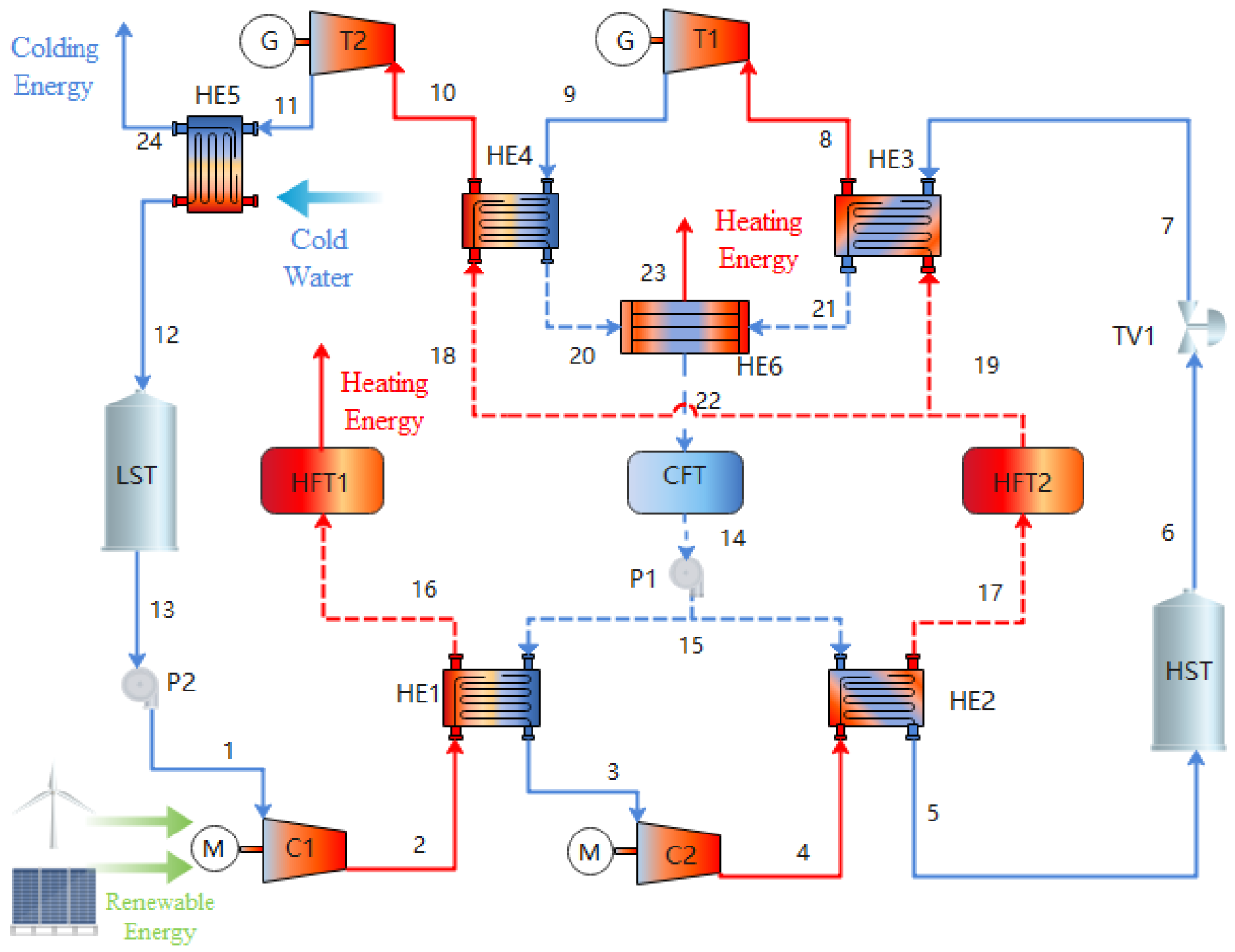
The CHP-based Closed Compressed CO
2 Energy Storage System (Closed-CCES) primarily contains compressors C
1 and C
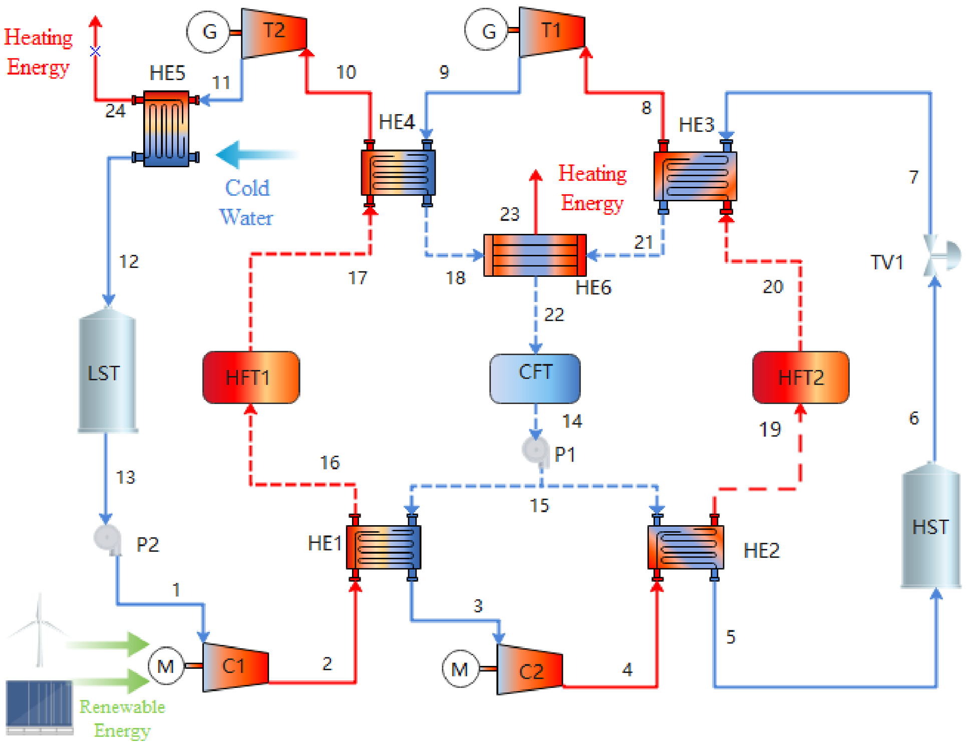
2, coolers HE1 and HE2, high-pressure gas storage device HST, throttle valve TV1, heaters HE3 and HE4, turbines T1 and T2, aftercooler HE5, low-pressure gas storage device LST, thermal storage devices HFT1 and HFT2, cold tank CFT, and heat transfer oil waste heat recovery device HE6, as denoted in
Figure 1. In the ES stage, excess or renewable electricity is utilized to compress the carbon dioxide in the low-pressure gas storage device LST. The compressed carbon dioxide is then cooled through cooler HE1, whereas the compression heat is transferred in the thermal storage device HFT1 via HE1. Compressor C2 is employed to further compress the cooled carbon dioxide, which is then cooled through cooler HE2, and the compression heat is preserved in the thermal storage device HFT2. The twice-cooled carbon dioxide ultimately enters the high-pressure gas storage device HST. The entire ES stage achieves the transition of electrical energy into the stored thermodynamic energy of CO
2.
During the energy release stage, the carbon dioxide stored in the HST first undergoes throttling and depressurization through the TV1. Then, it is heated in HE3 using the heat stored in HFT2 during the ES phase, heating the carbon dioxide to a supercritical state in preparation for subsequent expansion and power generation. Subsequently, the heated CO2 is passed through turbine T1 to expand to yield power. The CO2 is then reheated in HE4 using the heat stored in HFT1 during the ES stage. The heated carbon dioxide enters the next stage turbine T2 to expand and generate electricity.
The temperature of CO2 flowing out of the turbine T2 is still higher than the ambient temperature, with low-grade thermal energy. After the waste heat is utilized (such as domestic heating) by the aftercooler HE5, the flowing-out CO2 is preserved back in the LST for reuse in next cycle.
In addition, the heat carrier (heat-conducting oil) after heat exchange in the heaters HE3 and HE4 still has low-grade thermal energy, which can be utilized through the heat exchanger HE6. This approach is consistent with conventional waste heat recovery strategies for the energy storage system, which can effectively reduce energy waste while enhancing the system’s overall energy utilization rate. Following heat exchange, the heat carrier enters the cold tank CFT for storage, preparing for reuse in the next cycle.
2.2. CHP-Based Semi-Open Compressed CO2 Energy Storage System
CHP-based Semi-open Compressed CO
2 Energy Storage System (Semi-open-CCES) shares a similar component composition as the Closed-CCES system (in
Figure 2). The difference lies in that half of the compression heat of the Closed-CCES is utilized for heating the CO
2 for auxiliary power generation, while the other half is directly used for domestic heating. Due to the turbine output temperature in the Semi-open-CCES system being lower than the ambient temperature, the aftercooler HE5 is transformed from an exhaust heat utilization device into a cold utilization device, making it more flexible in energy utilization. In addition to outputting expansion work (for electric energy), it can also provide electricity, heating, and cooling outputs.
4. Results and Analysis
The system was implemented in a VC++ program. The model integrates the REFPROP library (NIST thermophysical property database) [
46] via low-level DLL interfaces to ensure high-precision calculation of the working fluid’s thermodynamic properties (e.g., CO
2). A sequential modular solution strategy was employed, where state parameters are calculated along the predefined flow path (e.g., compressor–cooler–storage tank–etc.). In this process, the outlet conditions of each upstream component serve as the inlet boundary conditions for the subsequent downstream component, advancing stepwise to resolve the entire cycle. Upon determining the thermodynamic state points (e.g., enthalpy, entropy, temperature, and pressure), the system performance is comprehensively evaluated in terms of cycle efficiency, exergy destruction, and parameter sensitivity.
4.1. Model Verification
To verify the accuracy of the model and the simulation program, the results reported in the literature were recalculated using the proposed program under the same parameter conditions as those in Ref. [
41]. The cycle efficiency calculated by the proposed model is 44.6%, compared with 46.51% reported in the literature, yielding a relative error of 4.1%. Similarly, the exergy efficiency obtained by the model is 52.47%, against the literature value of 54.29%, with a relative error of 3.3%. The small relative errors between the two sets of results confirm the rationality and reliability of the proposed model.
4.2. Analysis of Typical Design Working Conditions
Under typical design conditions, thermodynamic analyses were conducted for the Closed-CCES and Semi-open-CCES systems.
Table 1 provides a comprehensive overview of the detailed parameter settings under typical design conditions for two CCES systems.
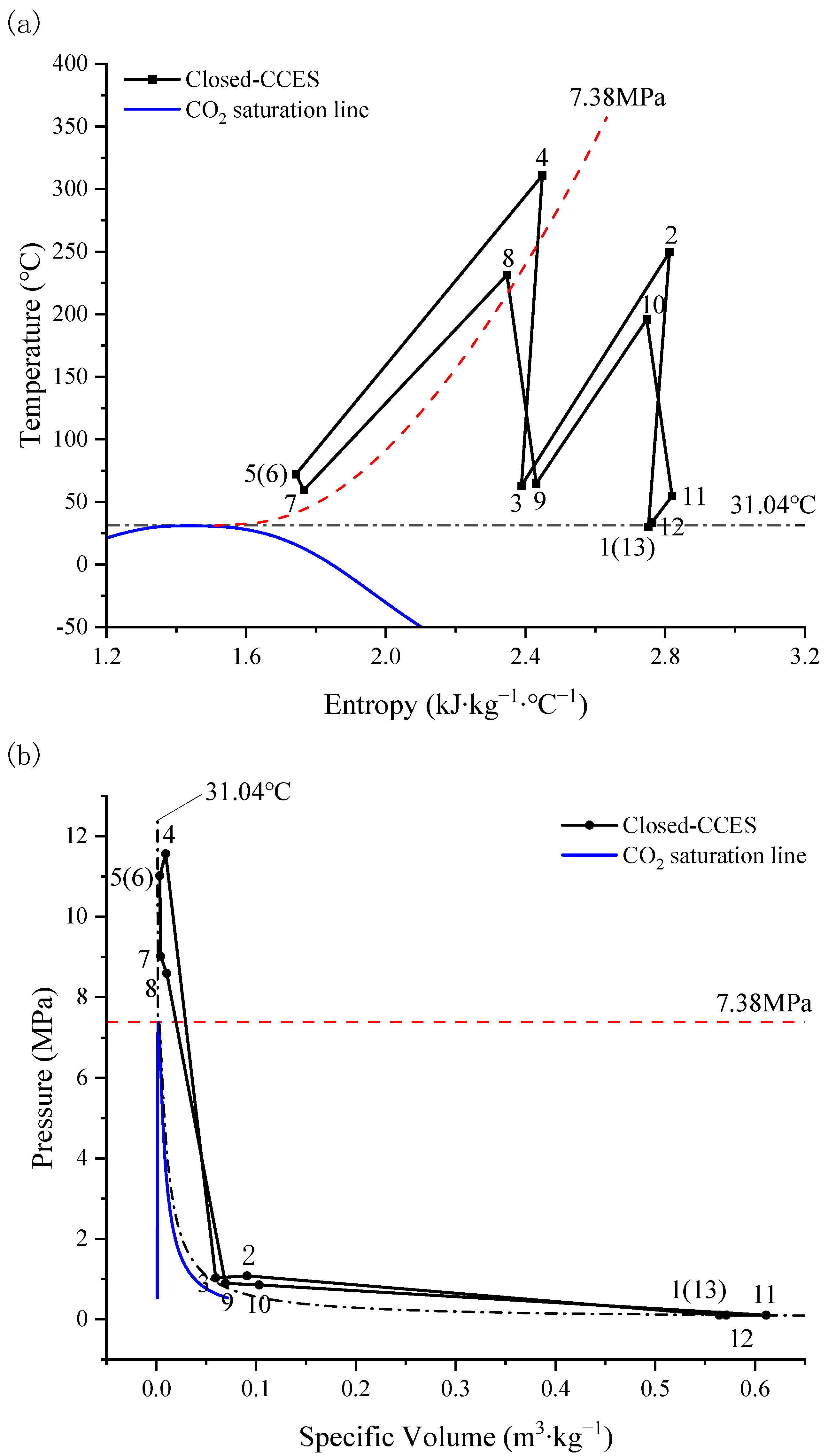
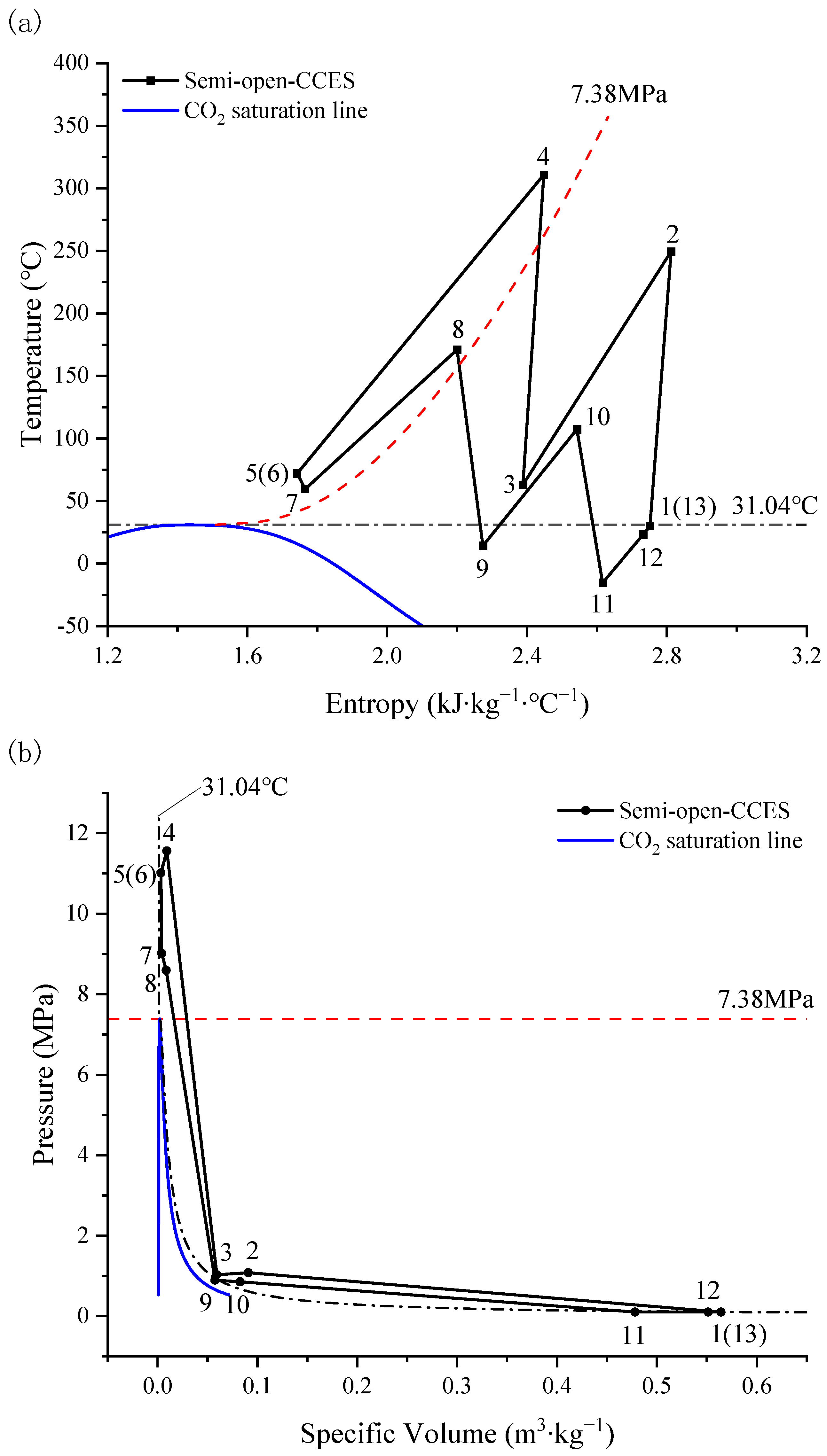
Figure 3 and
Figure 4 present the pressure–volume diagram and temperature–entropy diagram of the thermodynamic cycles for the two CCES systems.
Figure 3 shows that the Closed-CCES system cycle can operate across both subcritical and supercritical regions. In the ES stage, the pressure is rapidly increased through nearly isentropic compression processes (1–2, 3–4), transforming CO
2 from a subcritical state to a supercritical state. Through the nearly isobaric heat release process of CO
2 (2–3, 4–5), the heat of compression is preserved in the thermal storage device via a heat exchanger. During the energy release stage, the stored heat of compression is utilized for heating the CO
2 released from the high-pressure gas storage tank. The high-pressure supercritical CO
2 undergoes a nearly isentropic expansion process (8–9, 10–11) to perform work by reducing pressure, driving the turbine to yield electricity, and the CO
2 changes from a supercritical state to a subcritical state.
Similar to Closed-CCES, the Semi-open-CCES system cycle also achieves CO
2 operation across subcritical and supercritical regions. During the energy storage phase, CO
2 undergoes rapid pressure rise through a near-isentropic compression process (1–2, 3–4), transitioning from a subcritical state to a supercritical state. The compression heat is then preserved in the thermal storage device through a near-isobaric heat release process (2–3, 4–5). However, during the energy release stage, only half of the stored heat is utilized for heating CO
2 in the high-pressure storage tank, while the other half is applied. The supercritical CO
2 undergoes pressure reduction and performs work through a near-isentropic expansion process (8–9, 10–11), driving the turbine to yield electricity. Since the amount of heat used for heating CO
2 in Semi-open-CCES is reduced by half compared to Closed-CCES, the temperature during the energy release in Semi-open-CCES is lower, and the outlet temperatures of both stages of the turbine are below ambient temperature (in
Figure 4).
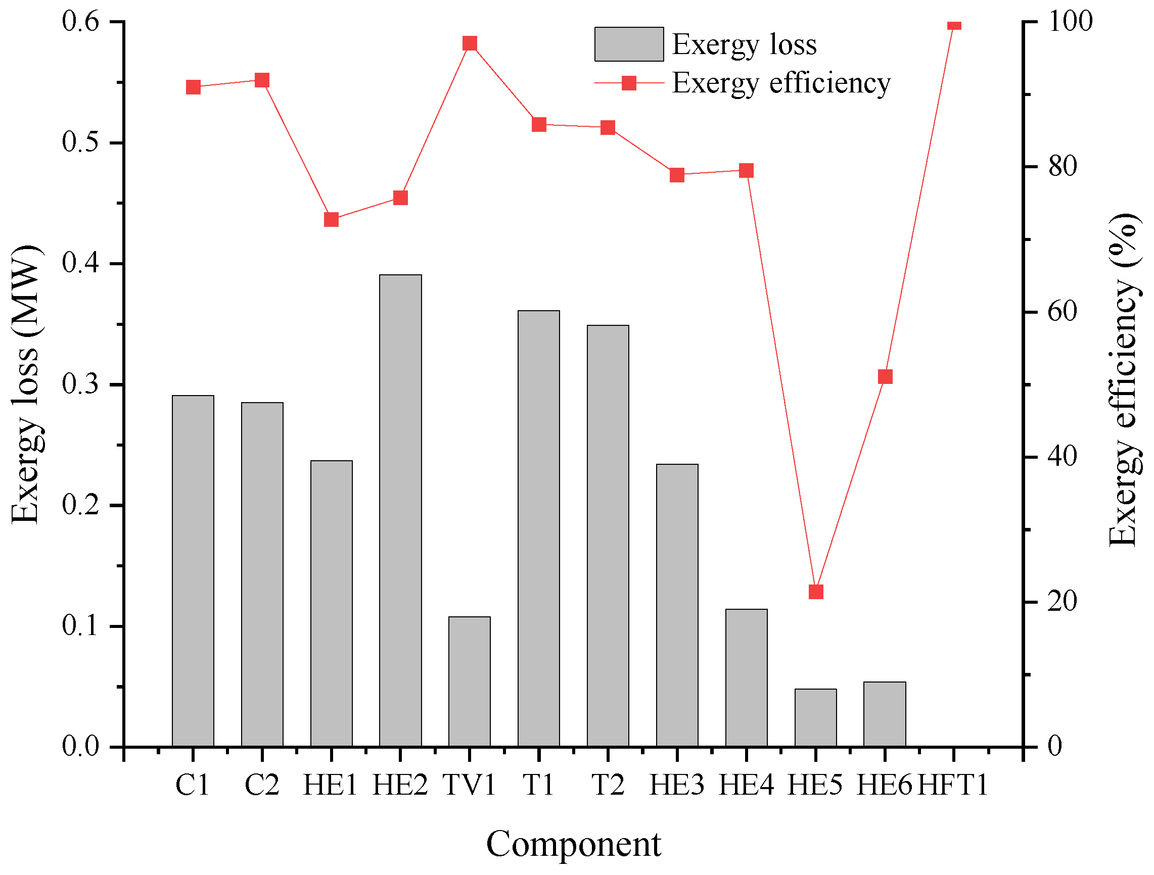
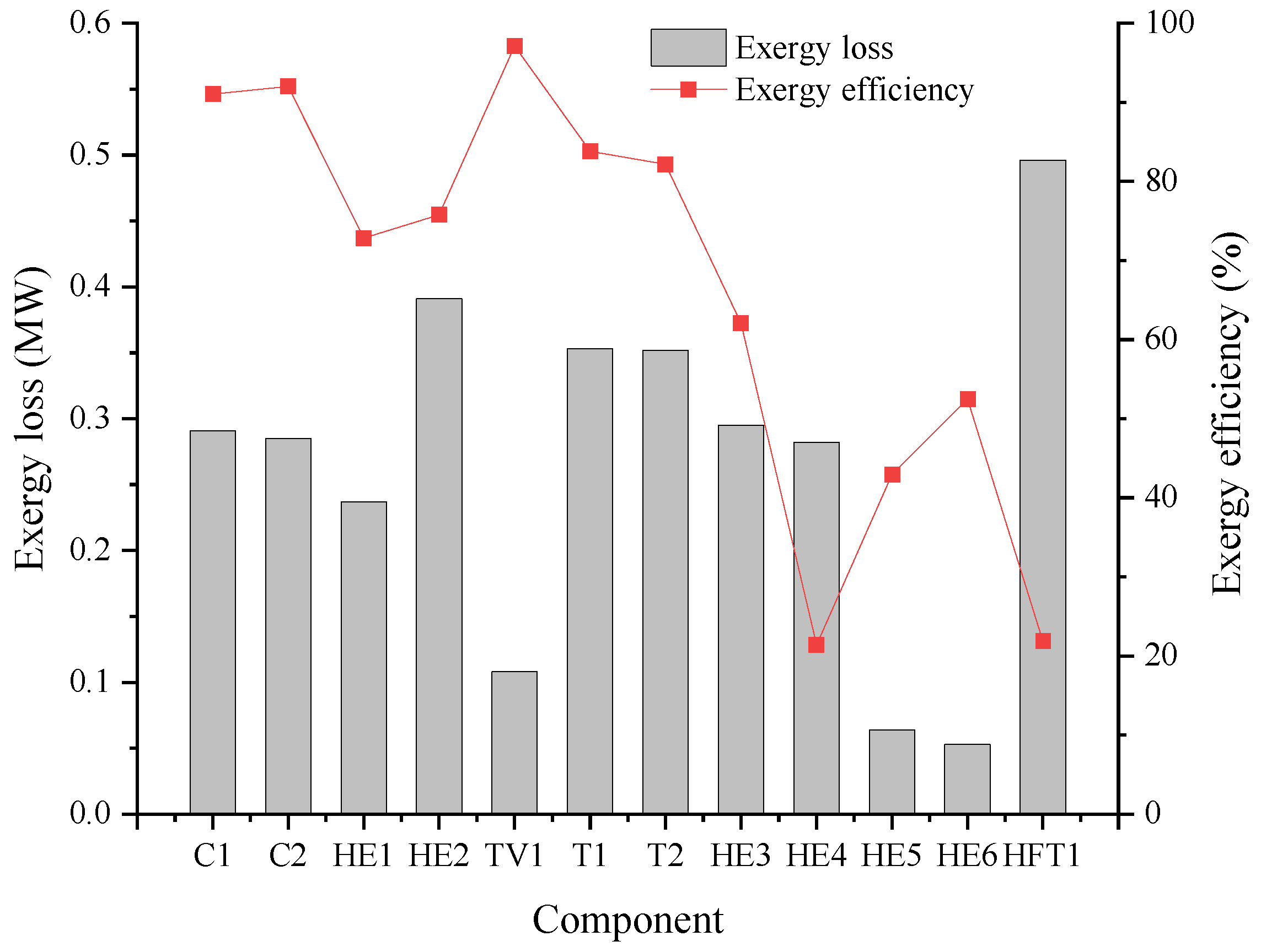
Table 2 presents the exergy loss analysis for the components of the Closed-CCES system. The components with the most significant exergy destruction are HE2, T1, and T2. Among them, heat exchanger HE2 exhibits the highest exergy loss, reaching 0.391 MW. This substantial loss is primarily attributed to the large temperature difference on the high-temperature, high-pressure side of the heat exchanger. Although its exergy efficiency reaches 75.78% (as shown in
Figure 5), the absolute exergy loss remains considerable due to the large thermal load it handles.
The exergy losses for turbines T1 and T2 are 0.361 MW and 0.349 MW, with exergy efficiencies of 85.85% and 85.46%, respectively. The considerable exergy destruction in these turbines is caused by internal flow friction, blade losses, and non-isentropic expansion, which to some extent compromises their work output capacity.
As can be seen from
Table 3, the components with significant exergy destruction in the Semi-open-CCES system include HFT1, HE2, T1, and T2. The heat storage device HFT1 exhibits the highest exergy loss, reaching 0.496 MW, with an exergy efficiency of only 21.89% (as shown in
Figure 6). This is because, during the process of HFT1 outputting thermal energy to the external environment in the Semi-open-CCES system, complex internal irreversibilities, such as mixing flow, heat transfer, and diffusion of the heat storage medium, become the core factors contributing to the high exergy loss and limiting the exergy efficiency.
The substantial exergy loss in HE2 is still attributed to the large temperature difference during heat transfer. Although turbines T1 and T2 exhibit relatively high exergy efficiencies, their considerable exergy destruction is still caused by the irreversibility of the internal thermodynamic processes of the working fluid.
According to the data presented in the
Table 2 and
Table 3, the Semi-open-CCES system exhibits an extremely low exergy efficiency in HE4 (21.40%), whereas the Closed-CCES system maintains a relatively high exergy efficiency (79.58%). The fundamental cause of this significant discrepancy lies in the degree of heat capacity flow rate matching between the fluids on both sides and the resulting irreversible exergy destruction due to heat transfer temperature differences. Based on the data presented in
Table 2 and
Table 3, and
Figure 1,
Figure 2,
Figure 3 and
Figure 4, a detailed analysis is provided as follows:
- (1)
The Semi-open-CCES system demonstrates a severe mismatch in heat capacity flow rates within HE4 (). The data indicates that the temperature variation amplitude on the thermal oil side () is substantially larger than that on the CO2 side (). This mismatch results in a massive heat transfer temperature difference during the process, particularly at the hot end, where the temperature difference reaches up to 138.86 °C. Such a large temperature difference drives a highly irreversible heat transfer process, leading to severe exergy destruction and, consequently, an extremely low exergy efficiency.
- (2)
In contrast, the Closed-CCES system achieves a favorable thermal balance. The temperature variation amplitudes of the fluids on both sides are very close (, ), indicating a high degree of heat capacity flow rate matching (). This matching ensures that the temperature differences at both the hot and cold ends are maintained at relatively low levels, which significantly mitigates the irreversibility of the heat transfer process. This well-matched flow condition represents an ideal scenario in heat exchanger design, as it maximizes the potential for temperature difference utilization, thereby sustaining a high exergy efficiency.
Based on the above exergy analysis results, differentiated optimization strategies are proposed. Priority should be given to improving the heat transfer matching characteristic of HE2 for Closed-CCES to reduce heat transfer temperature difference and cut down irreversible heat loss; meanwhile, the aerodynamic design of T1 and T2 can be optimized to increase isentropic efficiency. As for the Semi-open-CCES system, structural improvement and operating condition adjustment of HFT1 are essential to suppress internal multi-physical irreversible losses, and auxiliary performance promotion can be obtained by moderately optimizing HE2, T1 and T2.
Cycle efficiency and energy storage density serve as standard metrics for assessing thermodynamic performance, whereas the levelized cost of energy (LCOE) acts as a primary indicator for economic evaluation.
Table 4 lists the comparison of cycle efficiency, ESD, and LCOE results between the proposed energy storage system in this study and those in the literature. As can be seen from the data comparison in
Table 4, the proposed Closed-CCES system exhibits an advantage in terms of cycle efficiency, whereas the Semi-open-CCES system demonstrates superior energy storage density. From the economic perspective, the value LCOE of the Closed-CCES system is slightly lower than that of the Semi-open-CCES system, with both maintaining a slightly superior level when compared with other comparable systems.
4.3. Sensitivity Analysis
To delve into the effect of key parameters upon the CCES system, four key parameters have been chosen as decision variables: ambient temperature, storage pressure, heat exchanger efficiency, and discharge pressure. Within the same variation range for each parameter, the variation patterns of cycle efficiency, exergy efficiency, overall energy efficiency, and ESD for the two CCES systems have been analyzed, as well as their sensitivity to the decision variables.
4.3.1. The Impact of Ambient Temperature upon System Performance
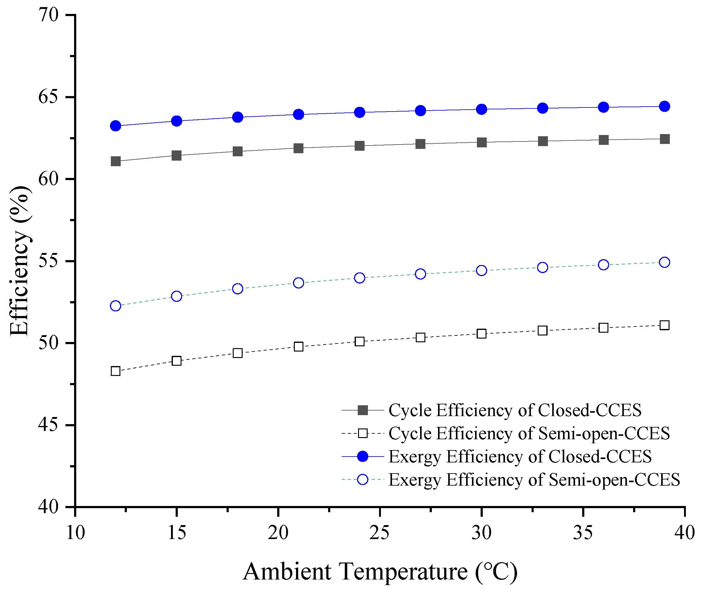
Ambient temperature influences the inlet and outlet temperatures of the compressor, consequently affecting the compressor’s power consumption, the thermal energy stored in the thermal energy storage device, and the output power of the turbine. These factors ultimately impact the overall performance of the system. The influence of ambient temperature, ranging from 12 °C to 39 °C, on the cycle efficiency, exergy efficiency, overall energy efficiency, and ESD of the two different system configurations has been investigated.
Under constant compression ratio, an increase in ambient temperature leads to a corresponding rise in the compressor discharge temperature, as well as the turbine inlet and exhaust temperatures. Although the power consumption of the compressor increases, the elevated turbine inlet temperature enhances its output work, thereby improving the power generation capacity of the unit and increasing both the cycle efficiency and exergy efficiency of the system. However, as the ambient temperature continues to rise, the disparity between the increase in turbine output work and the increase in compressor power consumption gradually diminishes. This phenomenon causes the rates of increase in both cycle efficiency and exergy efficiency to plateau as the ambient temperature rises.
As illustrated in
Figure 7, within the specified ambient temperature range, the cycle efficiency and exergy efficiency of the Closed-CCES system increase from 61.1% to 62.5% and from 63.2% to 64.4%, respectively, as the ambient temperature rises. The total increase in both metrics is less than 1.5%, indicating that the Closed-CCES system exhibits low sensitivity to variations in ambient temperature. For the Semi-open-CCES system, the cycle efficiency and exergy efficiency increase from 48.3% to 51.1% and from 52.3% to 54.9%, respectively, showing a marginal increase of approximately 3% over the entire temperature range, which demonstrates a weak positive correlation with ambient temperature. Furthermore, the cycle efficiency of the Closed-CCES system consistently exceeds that of the Semi-open-CCES system by approximately 10% to 13%. This significant difference indicates that the Closed-CCES system possesses lower irreversibility losses and superior thermodynamic performance.
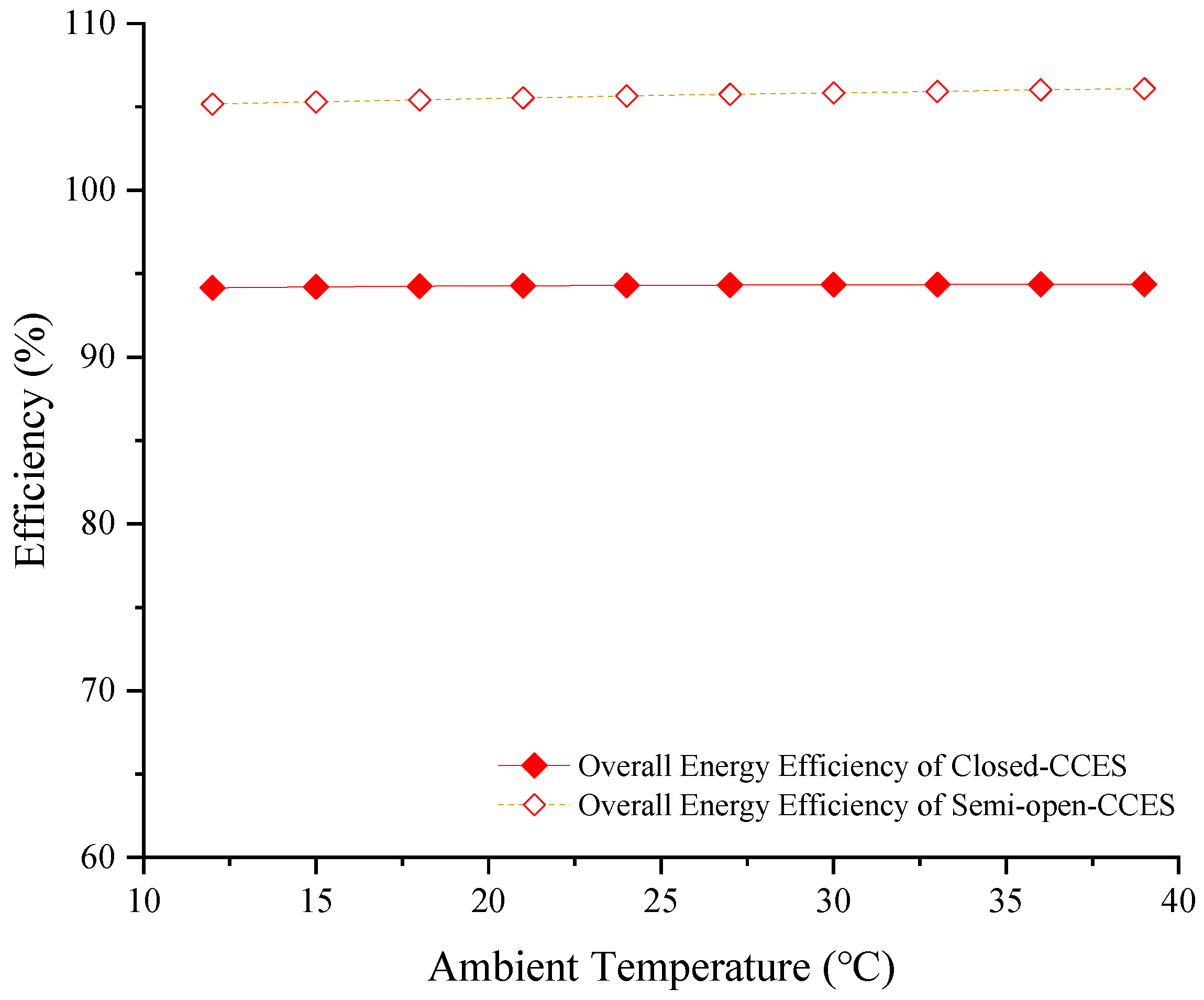
Meanwhile, as the discharge temperatures of both the compressor and the turbine increase, the temperature difference for heat exchange between the system and the environment enlarges. This increased temperature difference signifies enhanced heat transfer, resulting in greater heat and cooling output. However, due to the rise in ambient temperature, the compressor inlet temperature also increases, leading to higher compressor power consumption. Consequently, the overall improvement in energy efficiency is not significant (as shown in
Figure 8). Within the specified ambient temperature range, the energy efficiency of the Closed-CCES system increases marginally from 94.1% to 94.4%, representing a negligible increment of only 0.3%. Similarly, the energy efficiency of the Semi-open-CCES system rises from 105.2% to 106.1%, with a marginal increase of merely 0.9%. These results indicate that the energy efficiencies of both systems exhibit extremely weak sensitivity to variations in ambient temperature.
Due to structural differences (specifically, the Closed-CCES system does not directly reject heat to the environment during the thermodynamic cycle), it requires a greater amount of stored heat to warm the working fluid CO2 during the discharge phase. Consequently, its cycle efficiency and exergy efficiency are significantly higher than those of the Semi-open-CCES system. Conversely, the Semi-open-CCES system directly outputs heat and cooling to the external environment via the thermal energy storage device, resulting in a higher energy efficiency. Furthermore, because the exhaust temperature of the Semi-open-CCES system is lower than the ambient temperature, it can simultaneously provide cooling output alongside heat output (with a Coefficient of Performance, COP > 1). As a result, the total energy efficiency of the Semi-open-CCES system exceeds 100%. The differences in efficiency characteristics between the two systems stem from their respective technical approaches and structural features: the Closed-CCES system focuses on minimizing cycle losses, whereas the Semi-open-CCES system prioritizes high energy output. Both systems exhibit excellent adaptability to varying ambient temperatures, allowing users to select the configuration most suitable for their specific application scenarios.
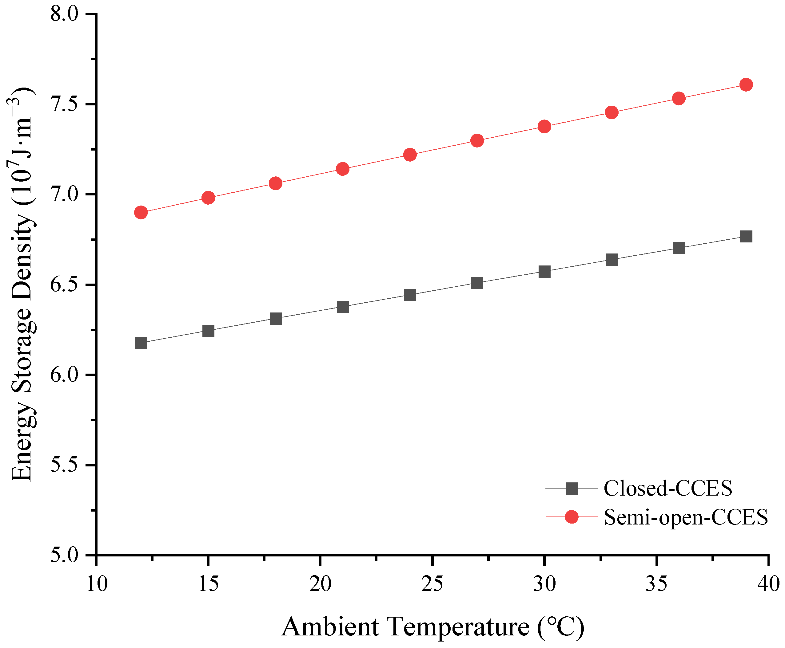
As the ambient temperature increases, the energy output of both systems increases. Under the condition of a constant storage tank volume, the energy storage density (ESD) of the systems also improves accordingly. As illustrated in
Figure 9, over the specified ambient temperature range, the ESD of the Closed-CCES system increases from 6.2 × 10
7 J·m
−3 to 6.8 × 10
7 J·m
−3, while that of the Semi-open-CCES system rises from 6.9 × 10
7 J·m
−3 to 7.6 × 10
7 J·m
−3. The increments in both systems are marginal, indicating a weak sensitivity to variations in ambient temperature. Due to its higher total energy output, the ESD of the Semi-open-CCES system is higher than that of the Closed-CCES system.
4.3.2. The Influence of ES Pressure upon System Performance
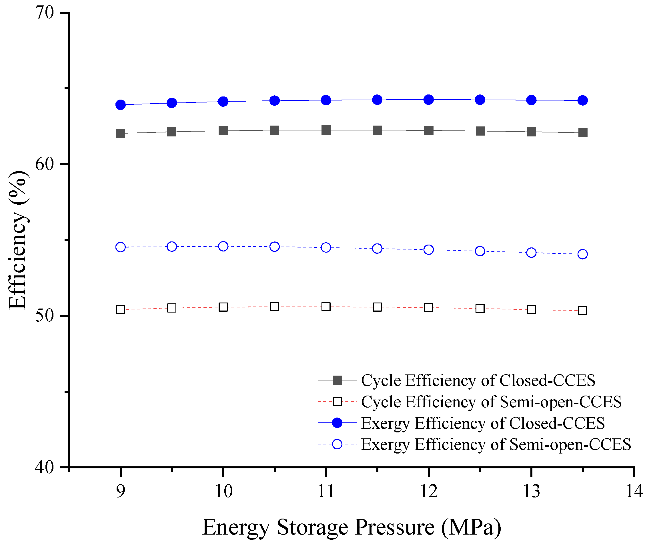
Fluctuations in storage pressure directly dictate the work of compression and expansion, significantly impacting system performance. The influence of storage pressure, ranging from 9 MPa to 13.5 MPa, on the cycle efficiency, exergy efficiency, overall energy efficiency, and ESD of the two different system configurations has been investigated.
As the energy storage pressure increases, the compressor outlet temperature rises, which in turn affects the compressor power consumption, turbine output work, and system heat output. At lower energy storage pressures, the growth rates of the turbine output work and system heat output exceed that of the compressor power consumption, leading to an increase in both the cycle efficiency and exergy efficiency of the system. However, once the energy storage pressure reaches a certain threshold, further pressure elevation makes compression more difficult and accelerates the increase in compressor power consumption. Consequently, both the cycle efficiency and exergy efficiency gradually decline with further increases in energy storage pressure, exhibiting a trend of initially increasing and then decreasing.
As illustrated in
Figure 10, within the specified pressure range, the cycle efficiency and exergy efficiency of the Closed-CCES system remain in the ranges of 62.0–62.3% and 63.9–64.3%, respectively. For the Semi-open-CCES system, the cycle efficiency and exergy efficiency are maintained at 50.3–50.6% and 54.0–54.6%, respectively. Given the negligible variations in both cycle and exergy efficiencies for the two systems, it can be concluded that they exhibit extremely low sensitivity to variations in energy storage pressure.
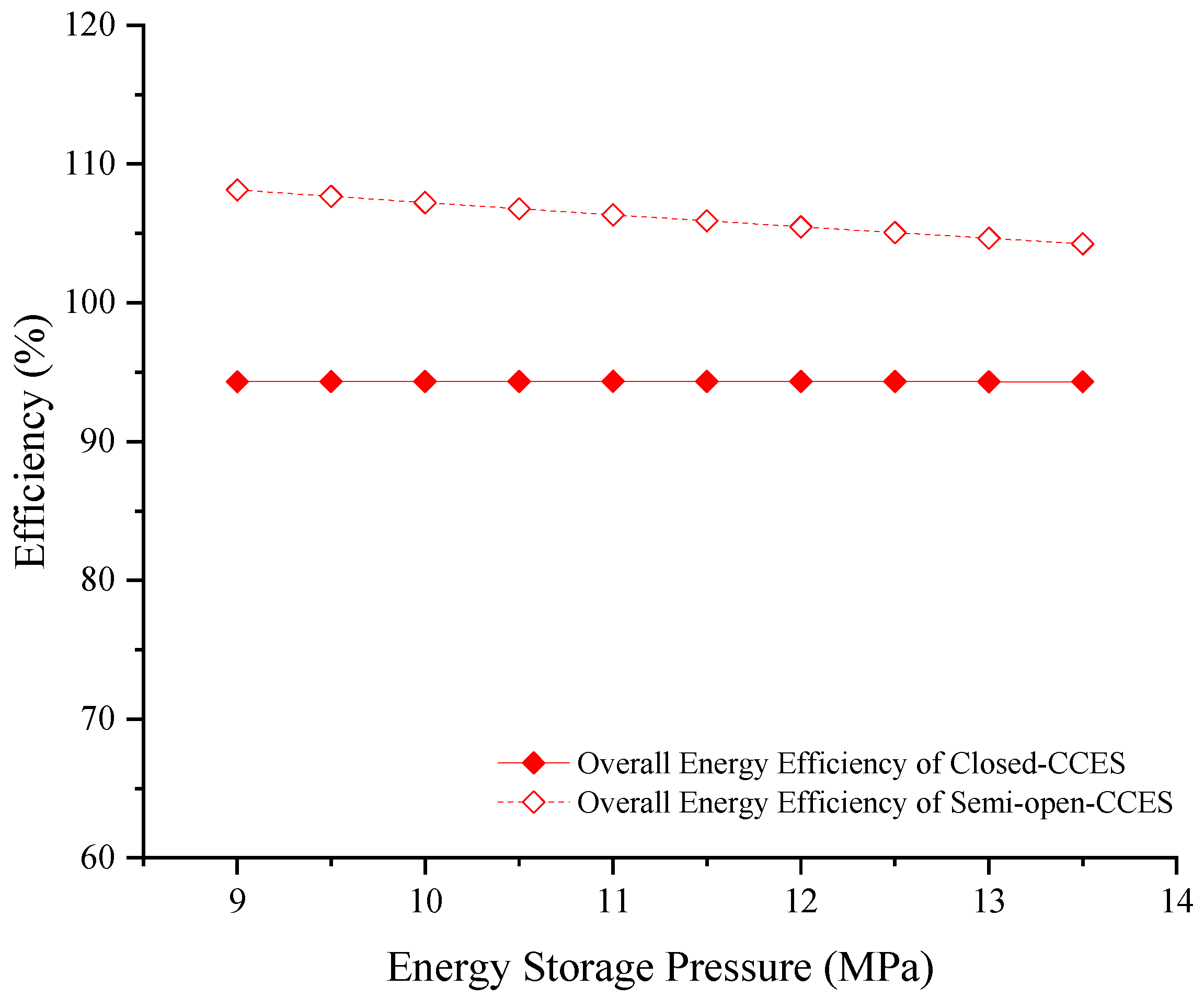
Meanwhile, as the energy storage pressure increases, the compressor outlet temperature rises, which consequently leads to an increase in both the inlet and outlet temperatures of the turbine. Under the premise of a constant ambient temperature, the temperature difference between the turbine outlet and the ambient environment decreases. As a result, the cooling capacity of the Semi-open-CCES system declines, leading to a reduction in its overall energy efficiency. In contrast, this variation in energy storage pressure has a minimal impact on the energy output of the Closed-CCES system, with no significant changes observed in its energy efficiency. As illustrated in
Figure 11, within the specified energy storage pressure range, the energy efficiency of the Closed-CCES system remains stable at approximately 93.3% with negligible fluctuations, indicating extremely low sensitivity to changes in energy storage pressure. Conversely, the energy efficiency of the Semi-open-CCES system decreases from 108.1% to 104.2%, representing an overall reduction of 3.9%. This demonstrates a weak negative correlation with the variation in energy storage pressure.
For the same reasons discussed above, under identical energy storage pressure conditions, the cycle efficiency and exergy efficiency of the Closed-CCES system are significantly higher than those of the Semi-open-CCES system. Conversely, the Semi-open-CCES system exhibits a higher energy efficiency.
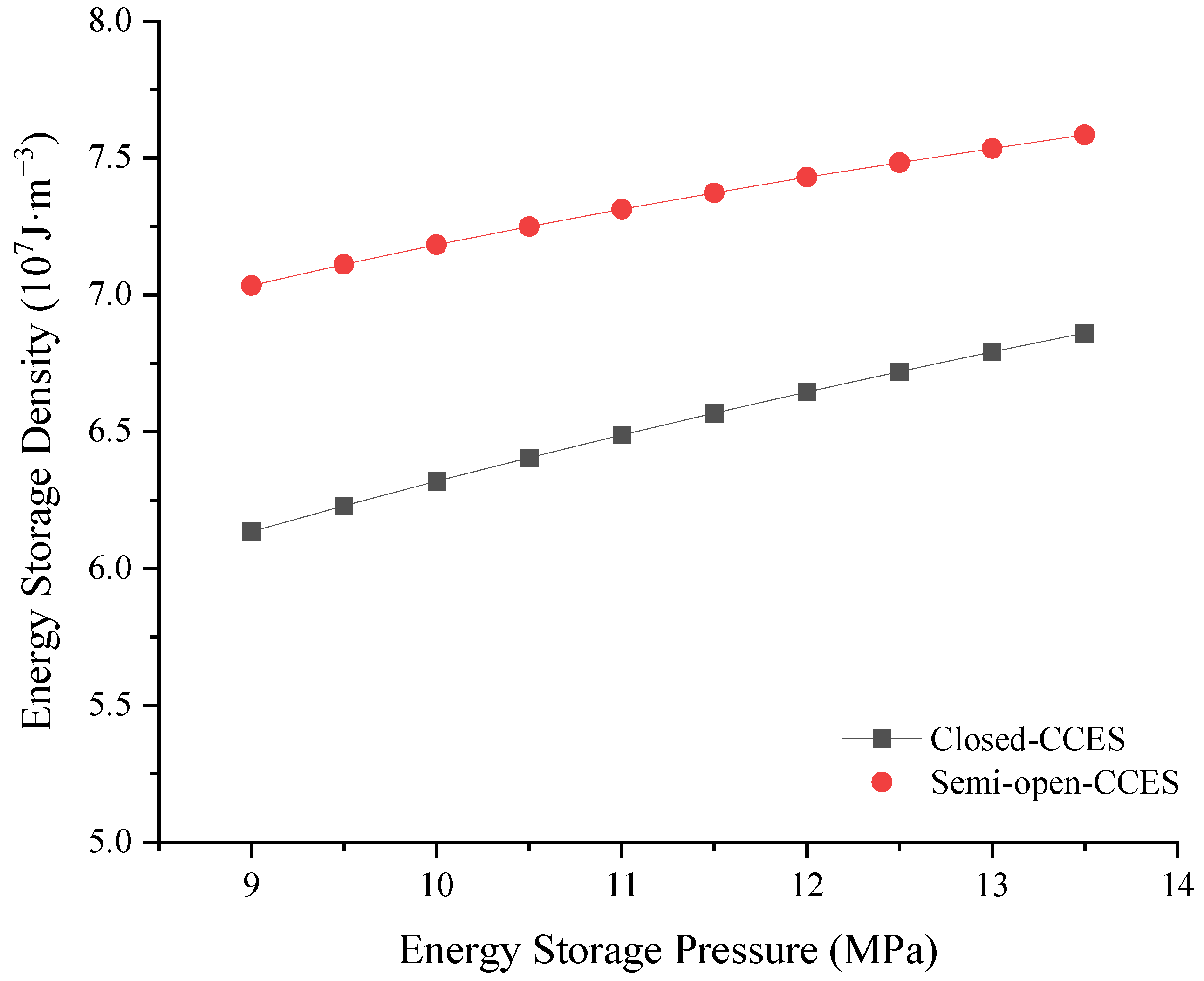
As the energy storage pressure increases, the pressure and temperature of the carbon dioxide during the energy release phase rise correspondingly, leading to a proportional increase in the generated work and heat. Although the system’s energy efficiency declines when the energy storage pressure reaches a certain threshold, this is attributed to the rapid escalation in compressor power consumption. In reality, the total energy output of the system continues to increase; consequently, the energy storage density (ESD) also increases with the elevation of the energy storage pressure. As illustrated in
Figure 12, within the specified pressure range, the ESD of the Closed-CCES system increases from 6.1 × 10
7 J·m
−3 to 6.9 × 10
7 J·m
−3, while that of the Semi-open-CCES system rises from 7.0 × 10
7 J·m
−3 to 7.6 × 10
7 J·m
−3. The marginal increments in both systems indicate a weak sensitivity to variations in energy storage pressure. Furthermore, due to its higher total energy output, the ESD of the Semi-open-CCES system consistently remains higher than that of the Closed-CCES system.
4.3.3. The Influence of Heat Exchanger Efficiency upon System Performance
As a critical thermodynamic component in CCES configurations, fluctuations in heat exchanger efficiency directly alter its heat transfer characteristics. By affecting the temperatures of both carbon dioxide and heat transfer oil, these fluctuations subsequently exert an indirect influence on the overall performance of the system. The influence of heat exchanger efficiency between 60% and 95% on cycle efficiency, exergy efficiency, overall energy efficiency, and ESD of two different system configurations has been investigated.
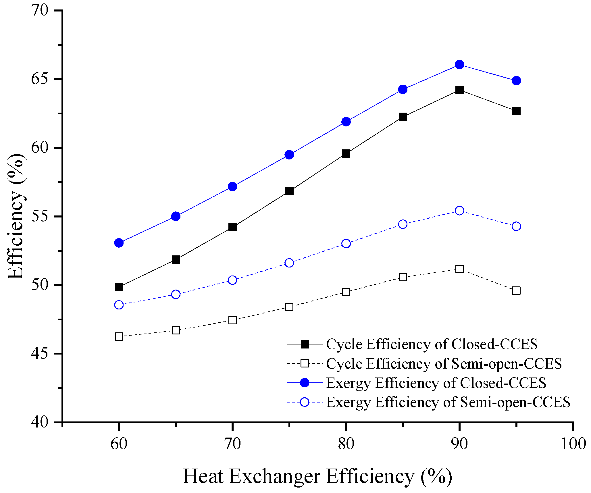
As the heat exchanger efficiency increases, the compression heat can be stored more efficiently. Consequently, the turbine inlet temperature rises correspondingly, leading to an increase in the output work, which is beneficial for improving both the cycle efficiency and the exergy efficiency of the system. However, an enhancement in heat exchanger efficiency also implies a more complex internal structure within the heat exchanger, which results in an increased pressure drop as the carbon dioxide flows through it. Therefore, with the initial increase in heat exchanger efficiency, both the cycle efficiency and the exergy efficiency of the system improve. Nevertheless, once the heat exchanger efficiency reaches a certain threshold, the increment in the system’s output work becomes insufficient to compensate for the pressure loss caused by the complex internal structure. At this point, both the cycle efficiency and the exergy efficiency begin to decline, exhibiting an overall trend of initially increasing and then decreasing. As illustrated in
Figure 13, as the heat exchanger efficiency increases, the cycle efficiency of the Closed-CCES system initially rises from 49.4% to a peak of 64.2% and subsequently declines to 62.6%. A similar trend is observed for its exergy efficiency, which increases from 53.1% to 66.0% before dropping to 64.8%. For the Semi-open-CCES system, the cycle efficiency increases from 46.2% to 51.1% and then decreases to 49.6%, while the exergy efficiency rises from 48.6% to 55.4% and then falls to 54.3%. Within the specified range of heat exchanger efficiency, both systems exhibit significant fluctuations in their cycle and exergy efficiencies. Consistent with the reasons discussed previously, the cycle efficiency and exergy efficiency of the Closed-CCES system consistently remain higher than those of the Semi-open-CCES system.
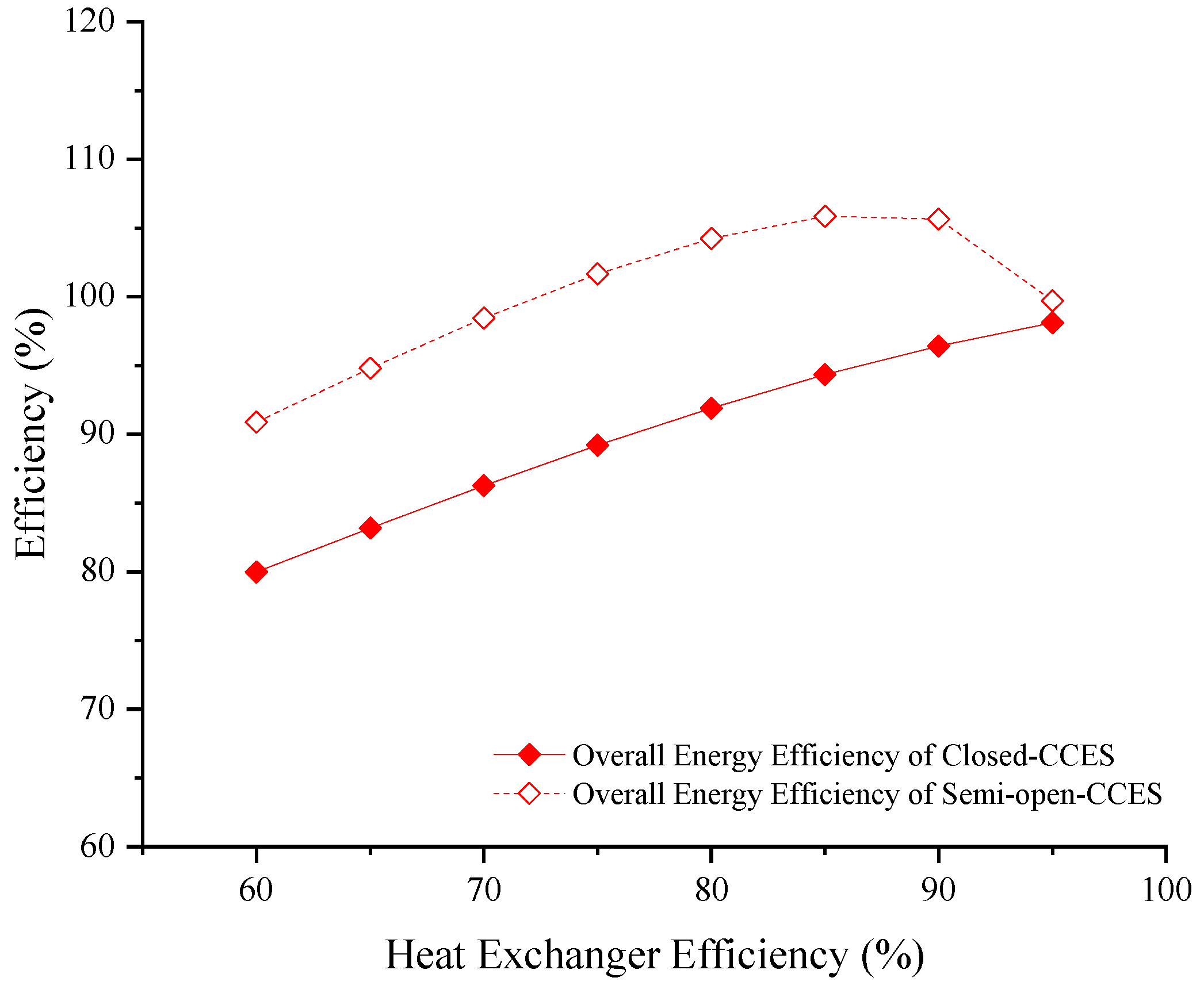
As previously mentioned, as the heat exchanger efficiency increases, the compression heat generated by the system can be stored and utilized more sufficiently. For the Closed-CCES system, while the compressor power consumption remains constant, the turbine inlet temperature rises and the output work increases, leading to an improvement in the system’s energy efficiency. As shown in
Figure 14, within the specified range of heat exchanger efficiency, the overall energy efficiency of the Closed-CCES system increases monotonically from 80.0% to 98.1%, representing a total increment of 18.1%. This indicates a high sensitivity to variations in heat exchanger efficiency. Conversely, for the Semi-open-CCES system, an increase in heat exchanger efficiency leads to a higher turbine outlet temperature. Under the premise of a constant ambient temperature, the system’s capacity to output cooling decreases. Consequently, the energy efficiency exhibits a trend of initially increasing and then decreasing. The overall energy efficiency rises from an initial 90.9% to a peak of 105.9%, and subsequently declines to 99.7%. The significant overall variation throughout the range also demonstrates a high sensitivity to changes in heat exchanger efficiency. Consistent with the reasons discussed previously, under identical heat exchanger efficiency conditions, the energy efficiency of the Semi-open-CCES system is significantly higher than that of the Closed-CCES system.
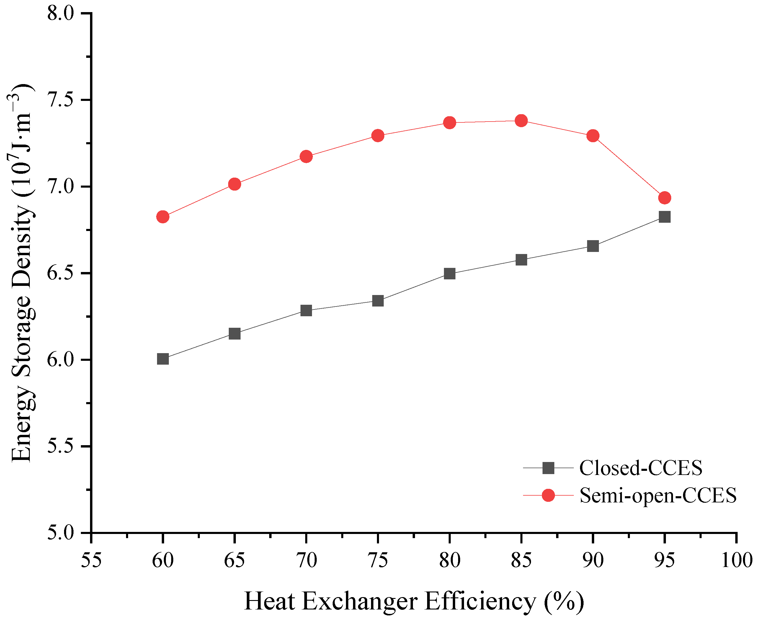
In addition to the volume of the gas storage vessel, the energy storage density (ESD) is also closely related to the total energy output of the system. Therefore, under the condition of a constant gas storage volume, the variation trend of the ESD curve exhibits a similar pattern to that of the energy efficiency. As illustrated in
Figure 15, within the specified range of heat exchanger efficiency, the energy storage density (ESD) of the Closed-CCES system increases monotonically from 6.0 × 10
7 J·m
−3 to 6.8 × 10
7 J·m
−3 as the heat exchanger efficiency improves, representing a total increment of 0.8 × 10
7 J·m
−3. In contrast, the ESD of the Semi-open-CCES system initially rises from 6.8 × 10
7 J·m
−3 to a peak of 7.4 × 10
7 J·m
−3, and subsequently declines to 6.9 × 10
7 J·m
−3. The significant variations in the ESD of both systems throughout the entire range indicate that their energy storage densities are highly sensitive to changes in heat exchanger efficiency.
4.3.4. The Influence of Discharge Pressure upon System Performance
The magnitude of the pressure released by the low-pressure turbine directly affects the system’s expansion work, thus significantly influencing the system’s performance. The effects of release pressures ranging from 0.6 MPa to 2.0 MPa on the cycle efficiency, exergy efficiency, overall energy efficiency, and ESD of two different system configurations have been analyzed.
When the overall expansion ratio of the system is kept constant, an increase in the energy release pressure leads to an increased expansion ratio and enhanced work capacity in the low-pressure turbine, accompanied by a decreased expansion ratio and reduced work capacity in the high-pressure turbine. At lower energy release pressures, the increment in the output work of the low-pressure turbine is sufficient to compensate for the reduction in the high-pressure turbine. Consequently, the total work output of the system increases, leading to an improvement in the cycle efficiency. However, once the energy release pressure exceeds a certain threshold, further elevation causes the work capacity of the high-pressure turbine to decline rapidly, while the work capacity of the low-pressure turbine increases at a slower rate. This discrepancy makes the increment in the low-pressure turbine insufficient to offset the work loss in the high-pressure turbine, ultimately resulting in a decrease in both the cycle efficiency and the exergy efficiency. Overall, the efficiencies exhibit a trend of initially increasing and then decreasing.
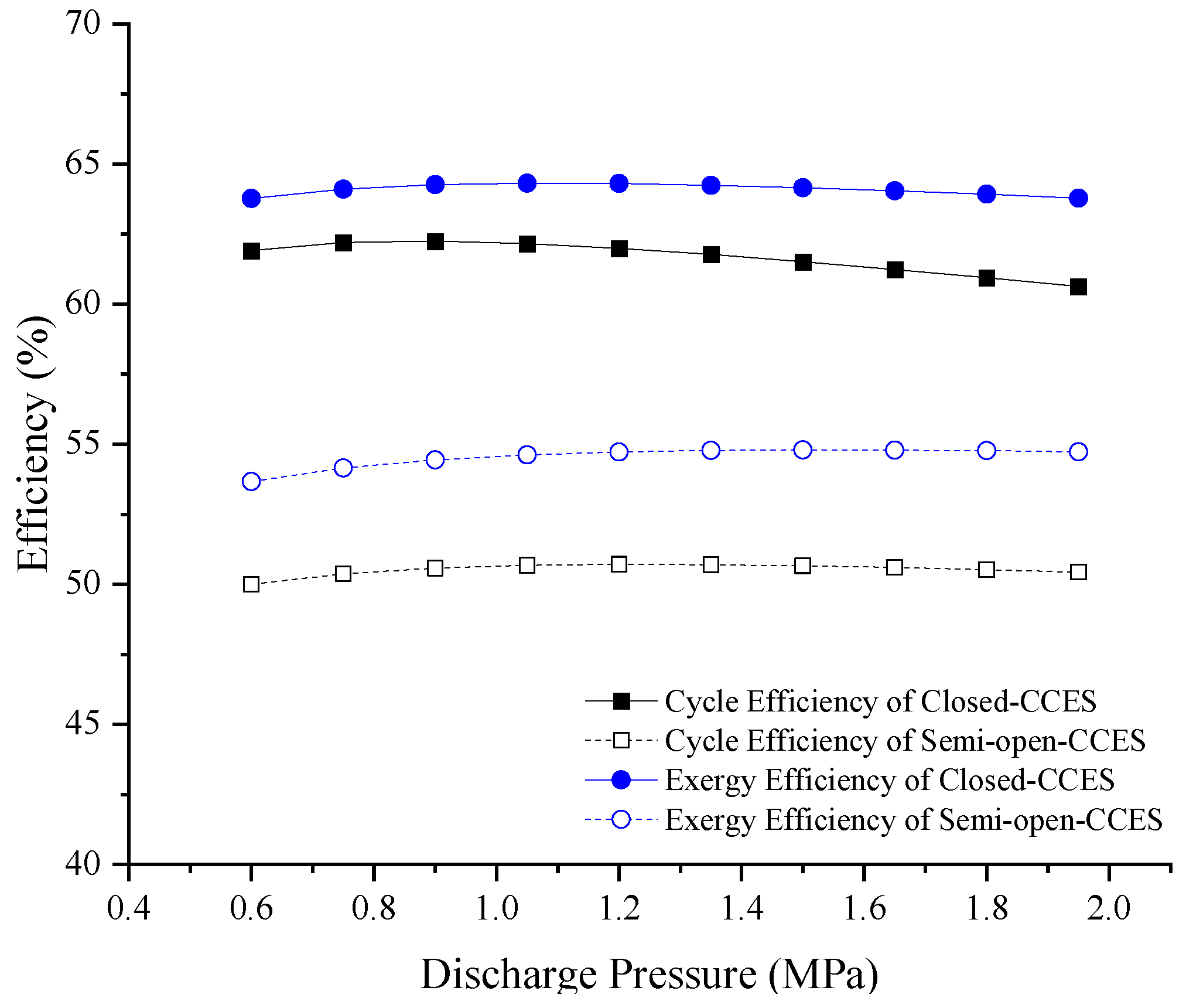
As illustrated in
Figure 16, as the energy release pressure increases, the cycle efficiency of the Closed-CCES system initially rises from 61.9% to a peak of 62.3% and subsequently declines to 60.6%. A similar trend is observed for its exergy efficiency, which increases from 63.7% to 64.3% before dropping to 63.8%. For the Semi-open-CCES system, the cycle efficiency increases from 50.0% to 50.7% and then decreases to 50.4%, while the exergy efficiency rises from 53.6% to 54.8% and then falls to 54.7%. Within the specified range of energy release pressure, the variations in both the cycle and exergy efficiencies of the two systems are relatively small, indicating a low sensitivity to changes in the energy release pressure. Consistent with the reasons discussed previously, the cycle efficiency and exergy efficiency of the Closed-CCES system consistently remain higher than those of the Semi-open-CCES system.
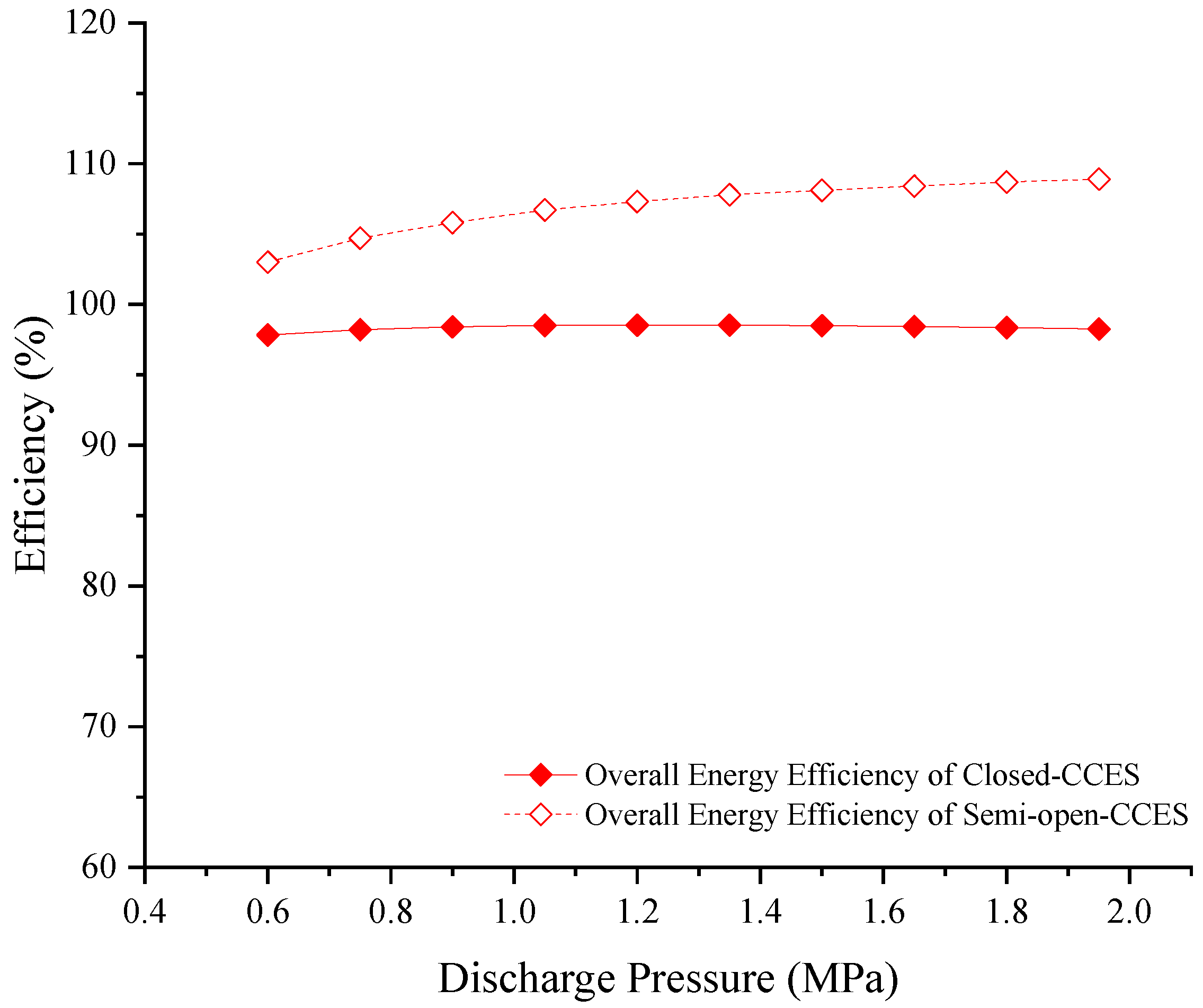
Figure 17 shows the impact of discharge pressure on overall energy efficiency of the two systems. For the Closed-CCES system, as the energy release pressure increases, the expansion ratio of the high-pressure turbine decreases. This leads to the insufficient expansion of carbon dioxide within the high-pressure turbine and a subsequent rise in the turbine outlet temperature. Consequently, the temperature of the heat transfer oil at the outlet of heat exchanger HE4 increases, resulting in a greater amount of heat output. Simultaneously, the expansion ratio of the low-pressure turbine increases, leading to a more complete expansion of the carbon dioxide and a decrease in the low-pressure turbine outlet temperature, which reduces the heat output. Considering the combined variations in the heat output from both turbine stages, the overall energy efficiency of the system exhibits a trend of initially increasing and then decreasing. Within the specified range of energy release pressure, the energy efficiency of the Closed-CCES system rises from 97.8% to a peak of 98.5% and subsequently declines to 98.2%. The marginal overall variation indicates an extremely low sensitivity of the energy efficiency to changes in the energy release pressure.
For the Semi-open-CCES system, the gradual increase in the energy release pressure leads to a more complete expansion of carbon dioxide in the low-pressure turbine. This causes a decrease in the outlet temperature of the low-pressure turbine and an enlarged temperature difference with the ambient environment, thereby increasing the cooling capacity output. Although the system’s output work gradually decreases after the energy release pressure reaches a certain threshold, the combined effects of these factors result in a continuous increase in the total energy output, leading to an improvement in the system’s energy efficiency. Within the specified range of energy release pressure, as the energy release pressure increases, the energy efficiency of the Semi-open-CCES system increases monotonically from 103% to 108.9%, representing an increment of 6.9% and demonstrating a stable upward trend.
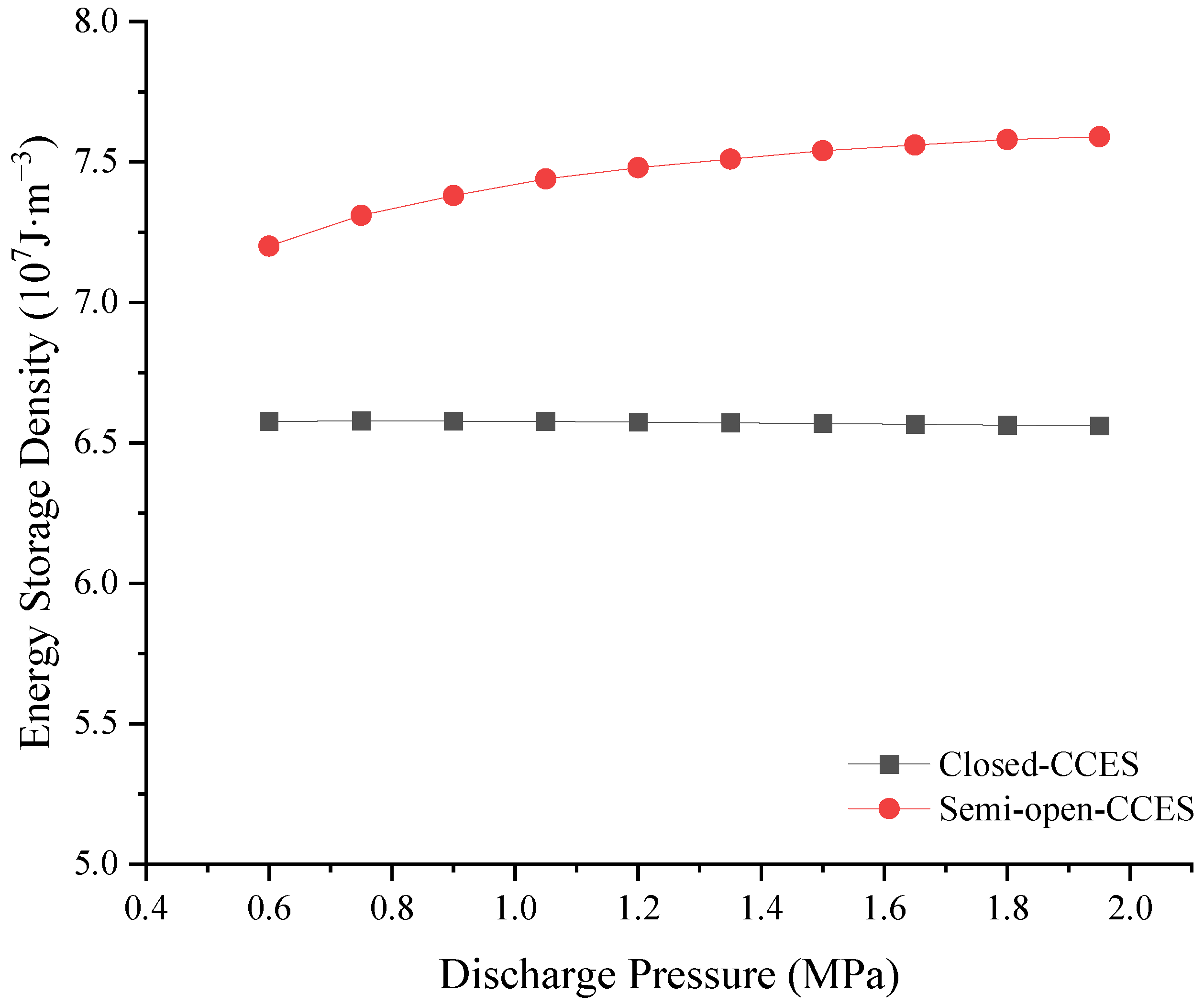
As the energy release pressure increases, the variation trend of the energy storage density (ESD) curve exhibits a similar pattern to that of the energy efficiency. As illustrated in
Figure 18, as the energy release pressure increases, the ESD of the Closed-CCES system remains stable at approximately 6.5 × 10
7 J·m
−3, demonstrating insensitivity to variations in the energy release pressure. Conversely, the ESD of the Semi-open-CCES system increases from 7.2 × 10
7 J·m
−3 to 7.6 × 10
7 J·m
−3, showing a marginal increment and a stable upward trend.
4.3.5. The Independence of Discharge Pressure and Heat Exchanger Efficiency upon System Performance
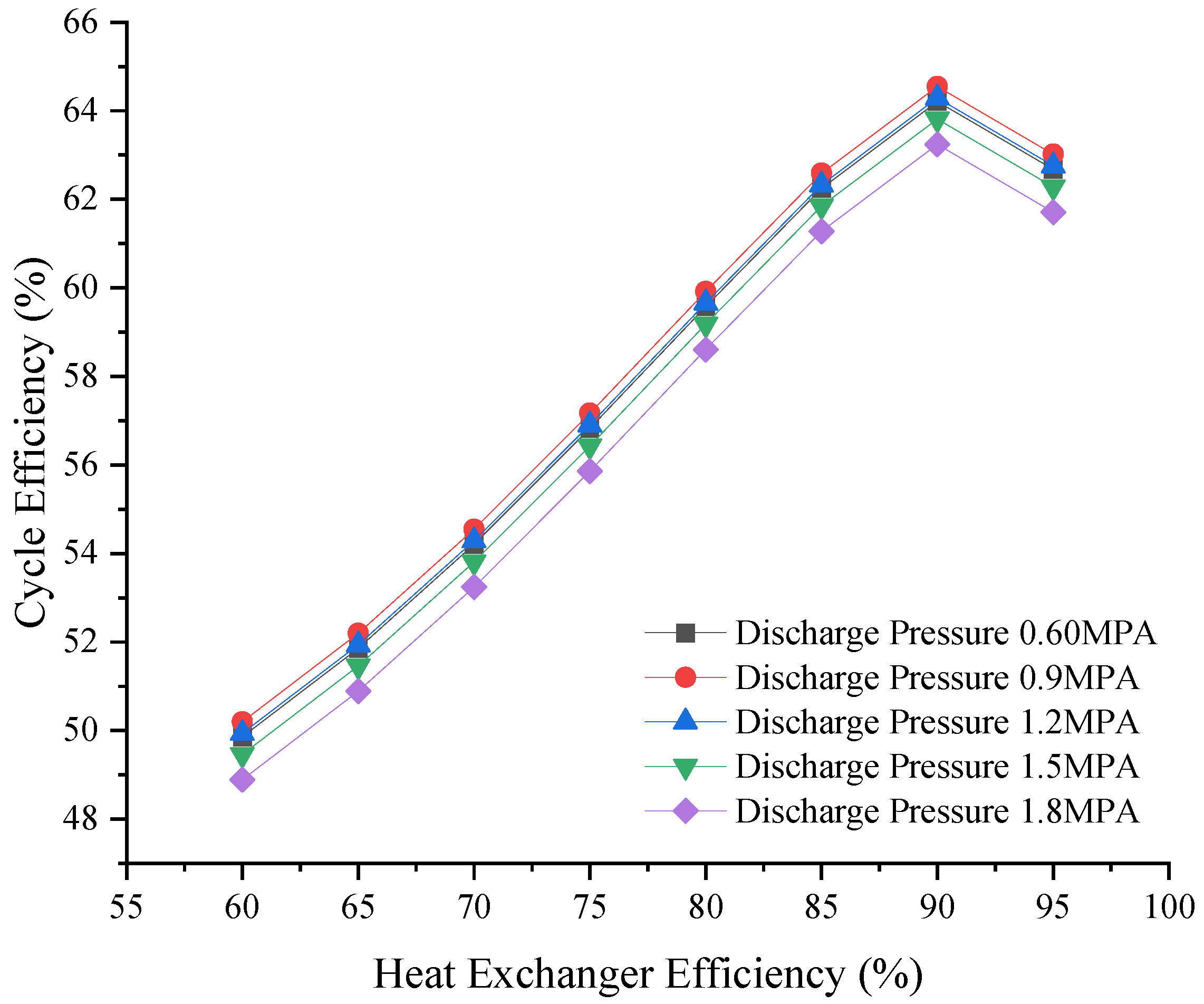
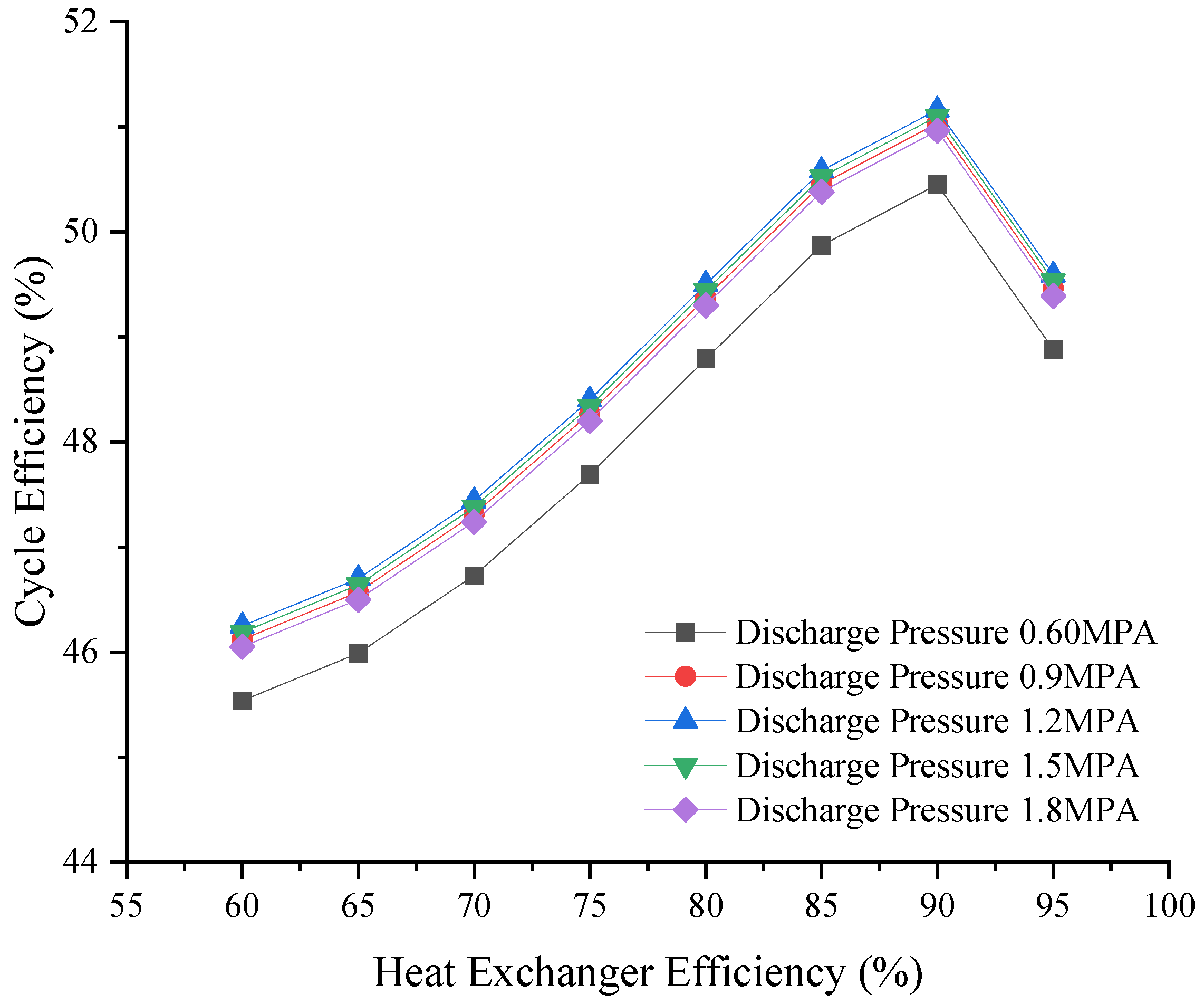
Figure 19 and
Figure 20 illustrate the variation of cycle efficiency with heat exchanger efficiency for the two systems under different energy release pressures. The results indicate that, regardless of the energy release pressure (ranging from 0.6 to 1.8 MPa), the peak cycle efficiency for both systems consistently occurs at a heat exchanger efficiency of approximately 90%. This demonstrates the robustness of the optimal heat exchanger efficiency, confirming that it is independent of the specific energy release pressure selected.
For the Closed-CCES system, at each heat exchanger efficiency level, the cycle efficiency initially increases slightly with rising energy release pressure from 0.6 MPa, reaching a peak at 0.9 MPa, and then gradually decreases. In contrast, the Semi-open-CCES system exhibits a trend of first increasing (peaking at 1.2 MPa) and then decreasing. These efficiency trends remain consistent across all heat exchanger efficiency levels, indicating that no significant coupling or abrupt transition exists between the two parameters.
In summary, the optimal operating conditions are identified as a heat exchanger efficiency of 90% and an energy release pressure of 0.9 MPa for the Closed-CCES system, and a heat exchanger efficiency of 90% and an energy release pressure of 1.2 MPa for the Semi-open-CCES system, with no notable coupling effect observed between the two parameters. Even when the heat exchanger efficiency cannot reach 90% due to manufacturing limitations, the same pressure-dependent trend can still be followed, allowing the energy release pressure to be fine-tuned according to practical heat exchanger costs to achieve optimal thermodynamic performance.
4.4. Economic Analysis
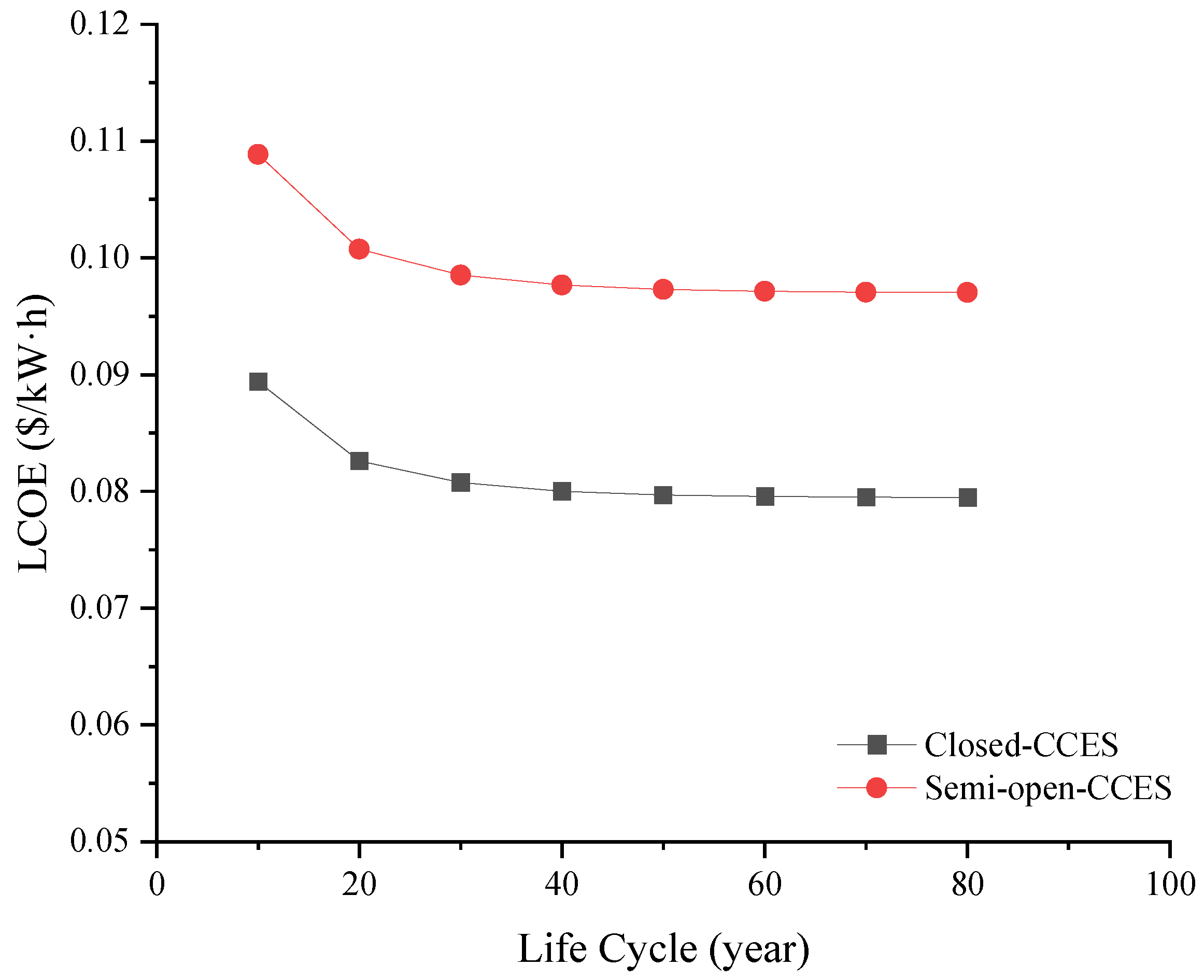
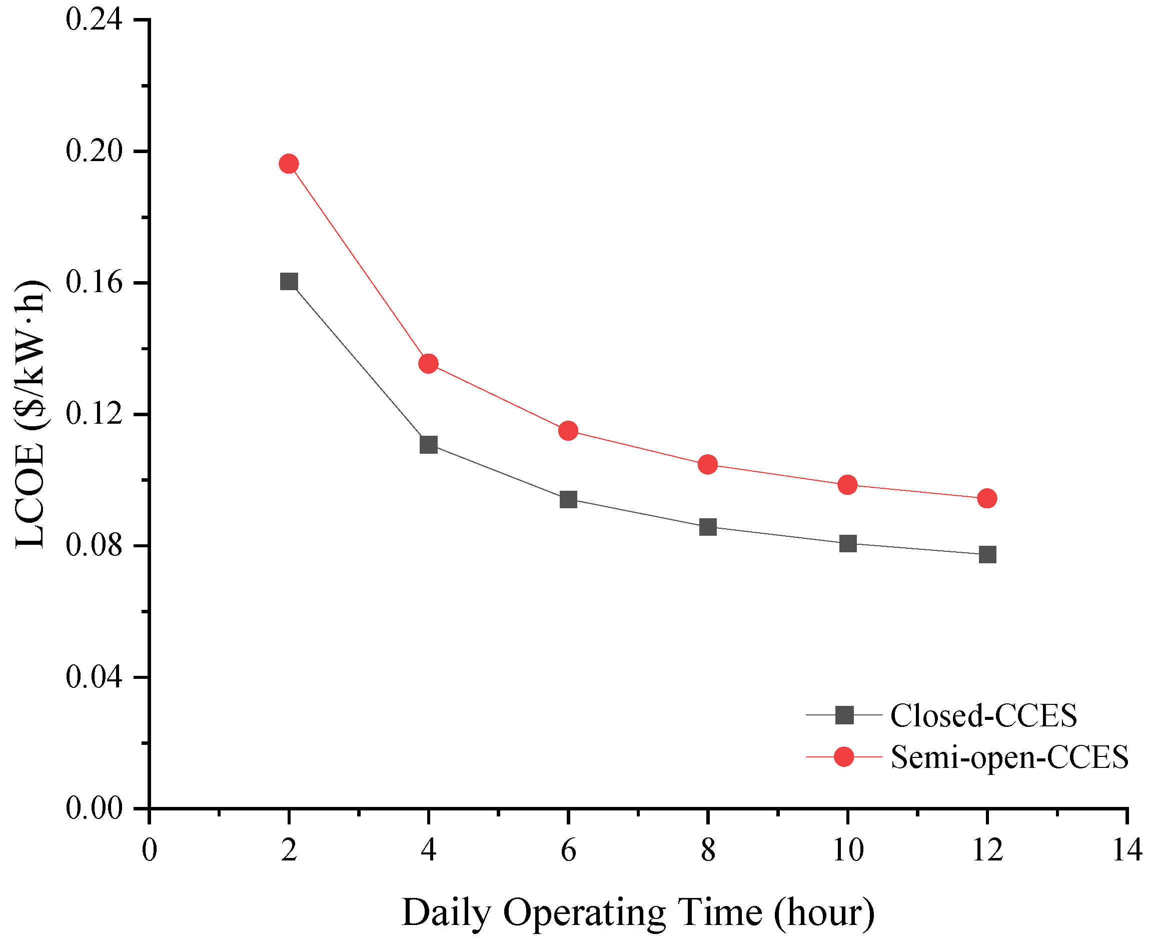
To comprehensively evaluate the economic characteristics of the Closed-CCES and Semi-open-CCES systems, this study examines the impacts of system life cycle and daily operating time on the levelized cost of electricity (LCOE), respectively.
4.4.1. Sensitivity Analysis of LCOE with Respect to System Life Cycle
Figure 21 illustrates the variation of LCOE for the Closed-CCES and Semi-open-CCES systems with system life cycle ranging from 10 to 80 years. Overall, as the life cycle extends, the LCOE of both systems exhibits a significant downward trend and eventually stabilizes. This indicates that extending the service life is a key factor in reducing the life-cycle cost of electricity. The specific variation characteristics can be divided into the following two stages:
- (1)
Rapid Decline Stage (10–40 years)
In the initial stage of system operation, the LCOE demonstrates high sensitivity to variations in the lifetime parameter. As shown in the figure, when the lifetime is extended from 10 to 40 years, the LCOE of the Semi-open-CCES system drops rapidly from approximately 0.109 $/kW·h to 0.097 $/kW·h, while that of the Closed-CCES system decreases from about 0.089 $/kW·h to 0.079 $/kW·h. The pronounced decline in this phase is primarily attributed to the Zero-Carbon Investment (ZCI) being amortized over an increasing total power generation, resulting in a significant marginal dilution effect that substantially lowers the unit electricity cost.
- (2)
Stable Plateau Stage (40–80 years)
When the lifetime exceeds 40 years, the slopes of both curves decrease significantly and tend to level off. At this stage, the LCOE of the Semi-open-CCES stabilizes at approximately 0.096 $/kW·h, while the Closed-CCES stabilizes around 0.079 $/kW·h. This suggests that the amortization effect of the initial investment is approaching its limit, and further reductions in LCOE are mainly constrained by factors such as Operation and Maintenance Expenditure (OPEX), capital costs, and residual value. Consequently, merely extending the physical lifetime yields diminishing economic returns. This inflection point suggests that for practical engineering applications, the focus should be placed on optimizing operational efficiency and maintenance strategies during the first 40 years.
- (3)
Comparison of System Economics
Throughout the entire lifetime under investigation, the LCOE of the Closed-CCES system remains consistently lower than that of the Semi-open-CCES system. Data indicates that the cost advantage of the Closed-CCES is maintained at approximately 0.02 $/kW·h, corresponding to a relative cost reduction of about 18–20%. This significant disparity confirms that the closed-loop system possesses superior economic potential, likely due to its structural design or thermodynamic cycle efficiency, thereby endowing it with stronger market competitiveness in long-term operations.
4.4.2. Sensitivity Analysis of LCOE with Respect to System Daily Operating Time
As illustrated in
Figure 22, the LCOE for both the Closed-CCES and Semi-open-CCES systems exhibits a significant downward trend with the extension of daily operating time. When the daily operating time increases from 2 to 12 h, the reduction in LCOE is particularly pronounced, indicating that enhancing system utilization is a critical pathway for lowering the cost of electricity. The specific variation patterns are as follows:
- (1)
High Sensitivity Interval (2–6 h)
In the phase characterized by shorter daily operating times, the LCOE demonstrates extremely high sensitivity to the duration of operation. The LCOE of the Semi-open-CCES drops sharply from approximately 0.195 $/kW·h to 0.115 $/kW·h, while that of the Closed-CCES decreases from about 0.160 $/kW·h to 0.095 $/kW·h. This steep decline is primarily attributed to the fixed capital investment being amortized over a greater number of generation hours. The capital expenditure per unit of electricity is rapidly diluted, thereby substantially reducing the overall LCOE.
- (2)
Diminishing Marginal Returns Interval (6–12 h)
When the daily operating time exceeds 6 h, the rate of LCOE reduction slows down markedly, and the curves tend to plateau. The LCOE of the Semi-open-CCES decreases gradually from 0.115 $/kW·h to 0.092 $/kW·h, whereas the LCOE of the Closed-CCES declines from 0.095 $/kW·h to 0.078$/kW·h. This indicates that as the operating time extends further, the amortization effect of the initial investment gradually weakens. Meanwhile, factors such as operation and maintenance costs (), the capital investment (), and equipment depreciation account for a relatively larger proportion of the total cost. Consequently, the optimization effect of merely increasing the operating time on the LCOE becomes less significant.
- (3)
Comparison of System Economics
Throughout the entire range of operating times investigated, the LCOE of the Closed-CCES system remains consistently lower than that of the Semi-open-CCES system. Although the cost gap between the two systems narrows slightly with the extension of operating time, the Closed-CCES maintains a cost advantage of approximately 0.015–0.035 $/kW·h, corresponding to a relative cost reduction of about 15–20%. This further validates that the Closed-CCES system possesses superior economic potential under conditions of long-duration and high-utilization operation.
5. Conclusions
Two CCES systems (Closed-CCES and Semi-open-CCES) according to supercritical/transcritical CO2 cycles have been proposed, and a thermodynamic model has been constructed to conduct a comparative analysis of their comprehensive performance. The key conclusions are listed below:
- (1)
Thermodynamic performance: The Closed-CCES system excels in stand-alone electricity storage applications. Under typical design conditions, its cycle efficiency and exergy efficiency are considerably higher than those of the Semi-open CCES system, rendering it more suitable for scenarios demanding high thermodynamic performance. In contrast, the Semi-open-CCES system demonstrates notable advantages in comprehensive energy utilization. By recovering compression heat for combined heating, power, and cooling supply, the system achieves a higher total energy efficiency, demonstrating effective thermal energy cascading. Moreover, the Semi-open-CCES system own higher energy storage density than that of the Closed-CCES system, making it more favorable for distributed energy supply applications.
- (2)
Exergy loss destruction: The primary exergy loss sources within the Closed-CCES system is the heat exchanger HE2. Therefore, it is recommended to adopt a structure combining multi-stage reheating with stratified heat exchange. By adapting the high-temperature section to the low-temperature winter environment and matching the low-temperature section to the high-temperature summer conditions, the irreversible losses caused by exergy destruction can be effectively mitigated. In the Semi-open-CCES system, the main exergy loss source is the thermal storage device HFT1. Therefore, it is recommended to implement cascaded thermal energy storage technology in combination with high-efficiency heat transfer media. This optimization strategy can significantly improve the overall cycle efficiency of the Semi-open-CCES system and demonstrates substantial potential for economic returns.
- (3)
Parameter Sensitivity: The ambient temperature and thermal storage pressure exert minimal impacts upon the cycle efficiency and exergy efficiency of both systems, indicating their good environmental adaptability. The heat exchanger efficiency wields a more remarkable impact upon the performance of the Closed-CCES system and is the focus of its optimization. The energy efficiency and ESD of the Semi-open-CCES system show a steady rise with an increase in discharge pressure, while the Closed-CCES system is insensitive to this parameter.
- (4)
Economic viability: The economic analysis, based on the levelized cost of electricity (LCOE), indicates that the Closed-CCES system is more economically favorable than the Semi-open-CCES system, achieving a notably lower LCOE. Compared with other energy storage systems, the two proposed CCES systems demonstrate a distinct advantage in terms of LCOE. For both systems, the LCOE decreases significantly with an extended system life cycle and increased daily operating hours, with the cost advantage of the Closed-CCES system remaining consistent across different scenarios.
The results demonstrate the potential of the two proposed CCES systems in large-scale energy storage and distributed energy systems, providing a foundation for the engineering application of carbon dioxide energy storage technology. A limitation of the present study is that an in-depth analysis regarding the impacts of individual component performance and seasonal variations in costs on overall system performance has not been conducted. Future research will focus on the local heat transfer characteristics of CCES systems, quantifying the impact of key component variables on overall system performance and economic feasibility, thereby helping to overcome technical bottlenecks in engineering applications. Overall, the two proposed CCES systems offer an integrated solution that addresses multiple pillars of sustainable development, environmental benignity (via CO2-based working fluids), grid flexibility (via large-scale renewable integration), energy efficiency (via cogeneration/trigeneration with a relatively high cycle efficiency and exergy efficiency), and economic feasibility (via favorable LCOE). These features collectively position the CCES technologies as viable pathways toward low-carbon power systems, aligning with the thematic priorities of sustainability, particularly in the areas of clean energy deployment, industrial decarbonization, and climate change mitigation.