Review

Advances in the Modification of Perovskite Solar Cells with Carbon-Based Materials and Corresponding Modification Strategies


1
School of Energy and Materials, Shihezi University, No. 280 Beisi Road, Shihezi 832000, China
2
College of Mechanical and Electrical Engineering, Shihezi University, No. 280 Beisi Road, Shihezi 832000, China
*
Author to whom correspondence should be addressed.
Sustainability 2026, 18(11), 5423; https://doi.org/10.3390/su18115423
Submission received: 16 April 2026 / Revised: 8 May 2026 / Accepted: 17 May 2026 / Published: 28 May 2026
(This article belongs to the Special Issue Advanced Study on Next Generation Solar Cells)

Abstract

As global energy demand continues to rise and the need for environmental conservation grows more urgent, solar energy has attracted substantial attention owing to its inherent cleanliness and sustainability. Perovskite solar cells (PSCs), an innovative photovoltaic technology, have shown significant improvements in photoelectric conversion efficiency (PCE) since their introduction. Nevertheless, significant challenges remain in enhancing efficiency and ensuring long-term stability. Naturally abundant and environmentally benign carbon materials represent a promising alternative. Incorporating carbon materials into PSCs can yield beneficial effects, such as controlling the crystallization rate of the perovskite layer, improving carrier transport properties, and realizing interface modification between various functional layers. This review systematically reviews the application of carbon materials in PSCs, including carbon nanotubes (CNT s), carbon dots (CDs), carbon nanofibers (CNFs), fullerenes, and their derivatives, thereby contributing to sustainable development by enhancing resource efficiency, device stability, and environmental compatibility of PSCs.

1. Introduction

As the global energy demand continues to rise and environmental protection becomes increasingly important, solar energy has emerged as a key area of research [1,2,3]. Among the various advancements in photovoltaic technology, PSCs are currently regarded as one of the most promising photovoltaic devices. Researchers have focused primarily on improving their PCE [4,5]. Since their first report in 2009, the efficiency of PSCs has risen remarkably from an initial 3.8% to a certified 27.3% [6]. This rapid progress has established PSCs as the fastest-developing photovoltaic technology, showing great potential for future solar energy applications [7,8]. The unique optoelectronic characteristics of metal halide perovskites fundamentally originate from their intrinsic electronic structure, which endows these materials with superior optical absorption capability, high carrier mobility, excellent defect tolerance, long charge-carrier diffusion length, distinctive bipolar charge transport behavior and facile bandgap tunability. Such remarkable physicochemical features have rendered metal halide perovskites one of the most attractive research focuses in the field of photovoltaic devices [9].
Although the PCE of PSCs has improved significantly, the inherent drawbacks of these devices cannot be ignored. On one hand, the functional layers of PSCs are generally fabricated via spin-coating a precursor solution, followed by annealing to form the crystal lattice [10]. This crystallization process is strongly affected by temperature, humidity, and oxygen concentration. Moreover, other annealing parameters, including duration and atmospheric conditions, also exert notable influences on crystallization behavior. On the other hand, non-radiative recombination occurs between functional layers, which impairs the overall performance of PSCs [11,12]. Each functional layer possesses unique physical properties and processing requirements, which affect not only its own performance but also the interfacial compatibility between adjacent layers.
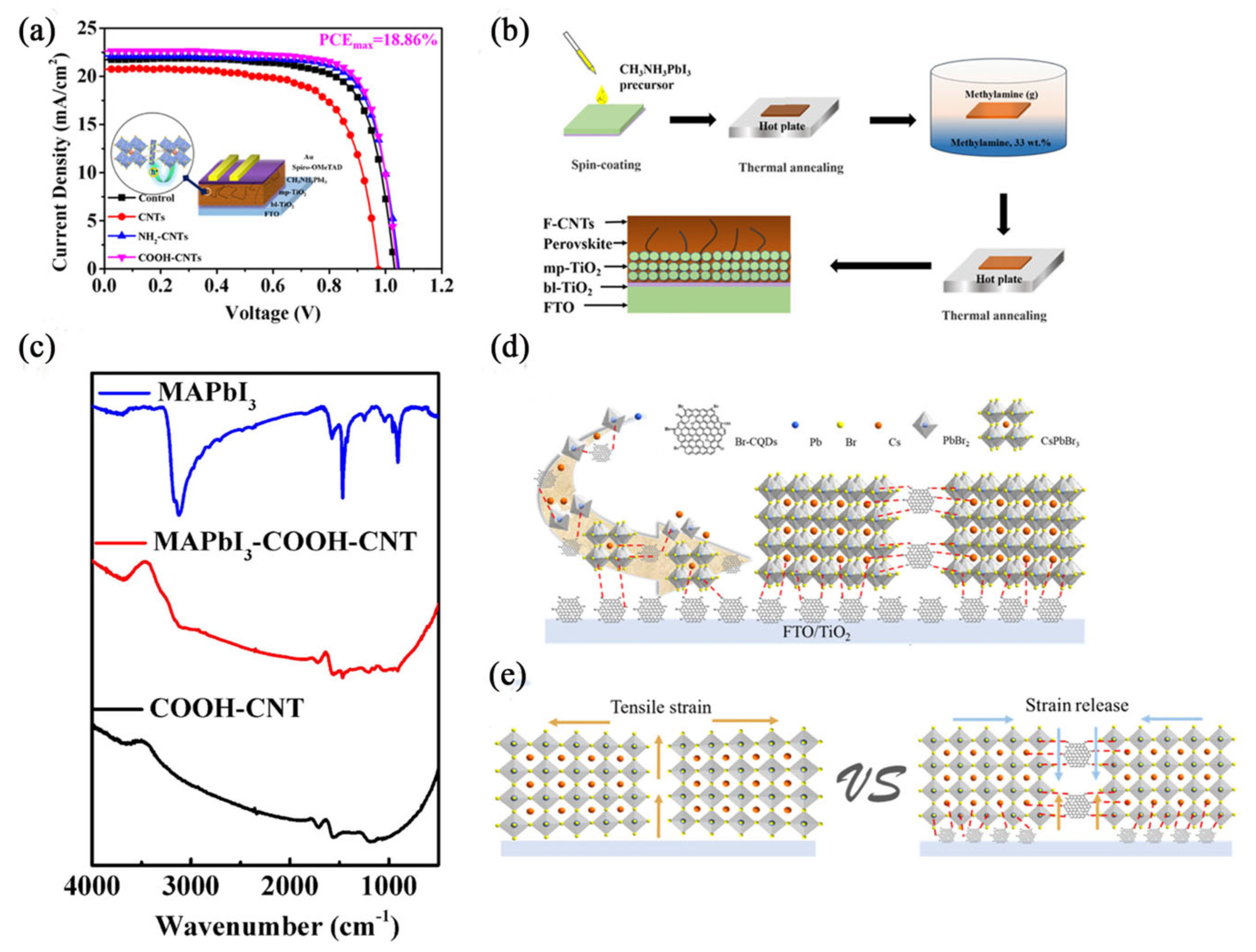
To address the challenges encountered in PSCs, researchers have utilized various strategies, including additive engineering, interface modification, and anti-solvent engineering. Yang et al. [13] introduced carboxylated carbon nanotubes (COOH-CNTs, multi-walled, metallic, with a diameter of 4–6 nmand a length of 0.5–2 µm, Nanjing XFNANO Ma terials Tech Co., Ltd., Nanjing, China) as additives into three typical perovskite systems, confirming that COOH-CNTs are high-efficiency modifiers for PSCs. This work demonstrates that COOH-CNTs comprehensively optimize PSC performance by regulating perovskite film crystallization, enhancing light harvesting, and accelerating carrier extraction and transport. After COOH-CNT incorporation, the PCE of (FAPbI3)0.97(MAPbBr3)0.03, MAPbBr3 and CsPbBr3 devices increased from 17.27%, 7.61% and 7.13% to 18.91%, 8.14% and 7.93%, respectively. COOH-CNTs can optimize perovskite crystallization to enlarge grain size and reduce pores and defects, while improving light absorption and photocurrent. In addition, COOH-CNTs with excellent conductivity build fast charge transport pathways, enhance hole mobility and suppress carrier recombination. Liu et al. [14] adopted high-conductivity multi-walled carbon nanotubes (MWCNTs, diameter 7–15 nm, length 0.5–10 µm, Sigma-Aldrich, St. Louis, MO, USA). and Liu-like polymers as binary co-additives for perovskite films. Carboxyl functionalization endows CNTs with the capability to selectively extract holes from perovskite and transport charges to the HTM. CNTs efficiently facilitate hole migration from perovskite grains to HTM, compensating for photocurrent loss and charge recombination induced by the low conductivity of Liu-like polymers. PSCs based on polymer-CNT composites achieved outstanding PCEs of 21.7% for small-area devices (0.16 cm2) and 20.7% for large-area devices (1.0 cm2). Benefiting from the intrinsic mechanical flexibility of polymers and CNTs, the composite enables the fabrication of flexible perovskite photovoltaic devices. The as-prepared flexible devices yield a highest PCE of 18.3%, retaining 80% of its initial efficiency after 1000 bending cycles, which exhibits superior mechanical stability and durability. Zhu et al. [15] synthesized Br-CQDs (Shanghai Mater Win New Materials Co., Ltd., Shanghai, China). Owing to the strong coordination of bromine and oxygen groups in Br-CQDs with uncoordinated Pb2+ and Cs+ ions in perovskite, as well as their insertion into the perovskite lattice, Br-CQDs act as a “binding agent”—effectively retarding perovskite nucleation and growth, repairing film defects, relieving lattice strain, and regulating interfacial energy levels. The formation of high-quality perovskite films and well-matched interfacial energy levels significantly reduces charge recombination and energy loss in PSCs. Ultimately, the hole-free PSCs achieve a PCE of 10.79% and an open-circuit voltage (Voc) of 1.651 V. The optimized devices exhibit excellent long-term stability under ambient conditions (85 °C, 85% relative humidity, and continuous illumination).
Carbon materials are abundant and cost-effective, diverse and exceptional properties that enhance the functional layers within PSCs. For instance, graphene demonstrates outstanding electrical conductivity. CNTs [16] and CNFs [17] function as conduits for electron and photon transport, thereby facilitating charge transfer. Furthermore, incorporating CDs [18] into the perovskite layer promotes the crystallization of the perovskite material. Chemical modification of carbon materials can introduce specific functional groups, enabling targeted interactions with the various functional layers of the perovskite and their interfaces. The stability of PSCs is critically dependent on humidity. The inherent hydrophobicity of carbon materials effectively mitigates the detrimental impact of moisture on device stability [13,19]. Due to their low cost and wide availability, using carbon materials to overcome existing limitations in PSCs is highly practical.
Doping modification of carbon materials can not only effectively passivate intrinsic defects (including vacancy defects, grain boundary defects, and surface dangling bonds) in perovskite films, but also inhibit interfacial ion migration and the erosion of perovskite active layers by ambient water and oxygen, thereby significantly optimizing the photoelectric performance (e.g., short-circuit current density, open-circuit voltage, and fill factor(FF)) and long-term operational stability of PSCs. Meanwhile, carbon-based raw materials feature wide availability, among which biomass-derived carbon can be sustainably regenerated; additionally, they exhibit prominent advantages such as low cost, non-toxicity without heavy metal contamination, and compatibility with low-temperature, low-energy-consumption preparation processes, which aligns with the green and low-carbon development orientation of advanced energy devices.
The extension of PSC service life effectively reduces the repeated input of raw materials and the generation of waste devices, thereby lowering resource consumption throughout the entire device life cycle. Moreover, the densification of perovskite films induced by carbon material doping further restrains the leaching and release of lead ions, which remarkably mitigates the potential risk of ecological pollution caused by lead-containing contaminants. Furthermore, the improvement of PCE of PSCs contributes to increasing energy output per unit area, which is conducive to promoting the large-scale application of PSCs and accelerating the substitution of traditional fossil energy with clean energy.
This review begins with an introduction to the fundamentals of PSCs. It then summarizes the classification of carbon materials, their modification sites, electrical transport characteristics, and modification strategies, as well as their interactions with perovskite structures. Furthermore, it outlines recent progress in the application of carbon-based materials in key components of PSCs, including the perovskite layer, electron transport layer (ETL), and hole transport layer (HTL). Finally, current challenges and future prospects for carbon material modification in PSCs are summarized and prospected.

2. Materials and Methods

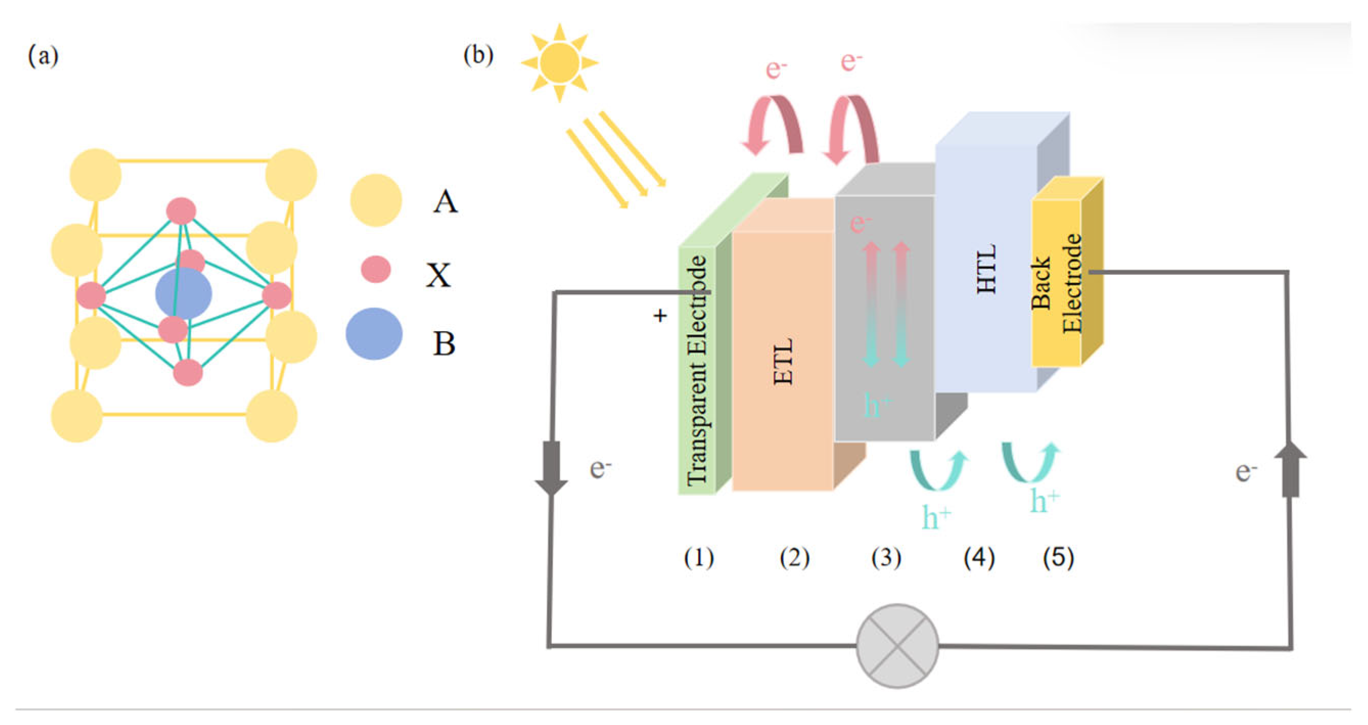
Perovskite has the chemical formula ABX3, with its cubic unit cell illustrated in Figure 1a. In this formula, A represents a monovalent cation, which can be an organic cation such as methylammonium (MA+) or formamidinium (FA+), an inorganic cation such as Cs+ or rubidium (Rb+), or a mixture of these cations [20,21,22]. B denotes a divalent metal cation, typically lead (Pb2+) or Sn2+. Lastly, X stands for a halide anion, which can be chloride (Cl), bromide (Br), or iodide (I). The main challenge facing perovskite materials is their long-term stability [23,24]. When exposed to humidity and oxygen in the environment, the perovskite layer can undergo degradation and eventually decompose [25,26].
The architecture of PSCs has seen significant advancements over the past decade. PSC structures can be broadly classified into two categories [27,28,29]: n-i-p (or mesoscopic) structures and p-i-n structures. In these configurations, n, i, and p represent electron-transporting, intrinsic, and hole-transporting semiconductors, respectively. In a n-i-p structure, the ETL is deposited onto a transparent electrode, followed by the perovskite active layer. The HTL is then coated onto the perovskite film, with a back electrode such as Ag [30] or Au [31] completing the device. In contrast, in a mesoporous structure, a thin compact TiO2 layer acts as a hole-blocking layer, while a mesoporous TiO2 [32,33] or ZnO scaffold serves as an electron-extracting layer that is infiltrated with the perovskite layer. In the p-i-n structure, the HTL is positioned underneath the perovskite layer, whereas the ETL is deposited above it and connected to a back electrode, typically Cu [34].
PSCs are primarily categorized into n-i-p and p-i-n structures [35,36,37]. A typical PSC consists of five essential components: (1) a transparent electrode, (2) an ETL, (3) a perovskite light absorption layer, (4) an HTL, and (5) a back electrode [38,39,40,41]. As illustrated in Figure 1b, the basic operating principle of a PSC involves the absorption of sunlight, which generates electron–hole pairs in the perovskite layer. The generated holes move to the HTL, while electrons migrate to the ETL. Subsequently, electrons and holes are extracted to the transparent electrode and the back electrode, respectively. This establishes an external circuit between the two electrodes [42,43,44]. For efficient electron and hole extraction, proper alignment of the valence band and conduction band energy levels among the functional layers is critical [45]. Favorable energy alignment improves charge transport and boosts the overall photovoltaic performance of the device.

3. Carbon Nanomaterials

Carbon nanomaterials exhibit excellent conductivity, stability and hydrophobicity. However, integrating high-density carbon nanomaterials into PSCs presents challenges because many of these materials are insoluble in common solvents, which is a characteristic inherent to carbon materials. To enhance their solubility and functionality, these carbon nanomaterials must be modified to incorporate specific functional groups that improve their compatibility with solvents [46].

3.1. Common Carbon Materials Applied in Perovskite Solar Cells

Common carbon materials can be classified into 0-dimensional (0D), 1-dimensional (1D), 2-dimensional (2D), and 3-dimensional (3D) carbon materials according to their dimensional structure [47]. Among them, 0D carbon materials include fullerenes [48], carbon quantum dots (CQDs) [49], etc.; 1D carbon materials include CNTs [14], CNFs [9], etc.; 2D carbon materials include graphene [50,51], graphene oxide (GO) [52,53], graphyne, etc.; and 3D carbon materials include graphite, porous carbon, diamond, etc. Common carbon materials used for modification include fullerenes, CQDs [54], CNTs [55], graphene, and their modified derivatives. The advantages and positions of common carbon materials being doped into PSCs are as described in Table 1.
CQDs are 0D carbon materials that exhibit excellent optical properties and good water solubility. They have a suitable optical band gap and can be derived from various raw materials, making them environmentally friendly and available in controllable sizes [56,57]. Due to these characteristics, CQDs are promising candidates for use as additives or dopants. They can enhance the conductivity of both ETL and HTL, and they can also modify the perovskite layer or its interface, leading to improvements in PCE and the long-term stability of PSCs [58]. However, CQDs prepared as additives or as intermediate-energy-level materials have limitations. They contain a limited number of oxygen-containing functional groups, which limits their ability to effectively passivate ionic defects within the perovskite thin film [15]. As a result, these CQDs cannot fully eliminate undesirable factors affect the performance of PSCs, thus limiting overall improvements in efficiency.
CNTs are recognized as ideal pathways for electron transport and as effective charge carriers due to their remarkable charge mobility, chemical stability, mechanical flexibility, high conductivity, and ability to be processed in solution [14]. They have found a wide range of applications in PSCs, serving roles such as transparent conductive electrodes, charge transport layers, perovskite layers, and back electrodes. CNTs have been shown to inhibit interfacial recombination, reduce hysteresis, and improve the stability of PSCs [59]. Additionally, CNTs as additives in the perovskite layer can modify the crystallization kinetics of the perovskite, leading to improved crystal quality and enhanced charge separation, which ultimately boosts the device’s performance. Nonetheless, the dispersion of CNTs within the perovskite active layer poses a significant challenge. Aggregation of CNTs can result in critical short circuits in PSCs [60].
Fullerenes are 0D, cage-like structures known for their high electron affinity and low recombination energy [61]. They serve as excellent electron acceptors, which benefits the separation and transport of electrical charge. Fullerenes can be used as an additive in several ways: at the interface between the charge transport layer and the perovskite light-absorbing layer or within either of those layers [62,63]. This application helps improve the morphology of the perovskite, increases its crystal grain size, and passivates charge defects at the surface and grain boundaries [64]. Fullerenes play a crucial role in reducing hysteresis and enhancing electron extraction. Moreover, due to their hydrophobic nature, fullerenes can act as a moisture barrier, reducing the corrosion caused by moisture exposure to the perovskite [65].
Graphene consists of sp2 hybrid carbon atoms organized in a honeycomb lattice. It possesses remarkable mechanical, optical, and bipolar electrical properties, as well as exceptional flexibility [66]. Graphene and its derivatives are increasingly utilized in the production of high-performance, low-cost, lightweight, and flexible energy devices to address the world’s limited energy resources [67]. Additionally, graphene and GO play crucial roles in various components of PSCs, including the electrodes, charge transport layers, light absorption layers, and interfaces between different functional layers.
Table 1. Advantages and position of common carbon materials doped into perovskite solar cells.
DimensionTypeAdvantagesPosition of ActionRefs.
0DFullerenesOutstanding electron acceptor, easy to dissolve.Between the charge transport layer and the perovskite layer, as well as within the charge transport layer and the perovskite layer[48]
CQDsOutstanding optical performance and good water solubility, with an appropriate optical band gap.ETL and HTL.[49]
1DCNTsWith excellent charge mobility, chemical stability, mechanical flexibility, high conductivity and the ability to be processed in solution.Perovskite layer[14]
2DGrapheneWith outstanding mechanical properties, optical properties and bipolar electrical properties, as well as extremely high flexibilityThe interfaces between the electrodes, the charge transport layer, the light absorption layer, and the various functional layers.[50,51]

3.2. Common Methods for Preparing Carbon Materials

Carbon materials exhibit exceptional photoelectric properties, environmental compatibility, and cost-effectiveness, which have generated significant research interest in PSCs. They are frequently integrated into functional layers or interfaces to enhance the PCE and stability of PSCs. However, the utilization of carbon materials is often limited to specific configurations, such as single-atom incorporation or additive roles. This limits their ability to effectively address internal device defects. The primary constraint arises from the insufficient density of active functional groups inherent to carbon materials, thereby impeding their capacity to achieve maximal defect passivation within the device architecture. Enhancing the performance of PSCs can be facilitated via chemical modification techniques, which improve the solubility of carbon materials, augment the density of effective functional groups, and elevate the abundance of oxygen-containing moieties.

3.2.1. Solid–Liquid Reaction

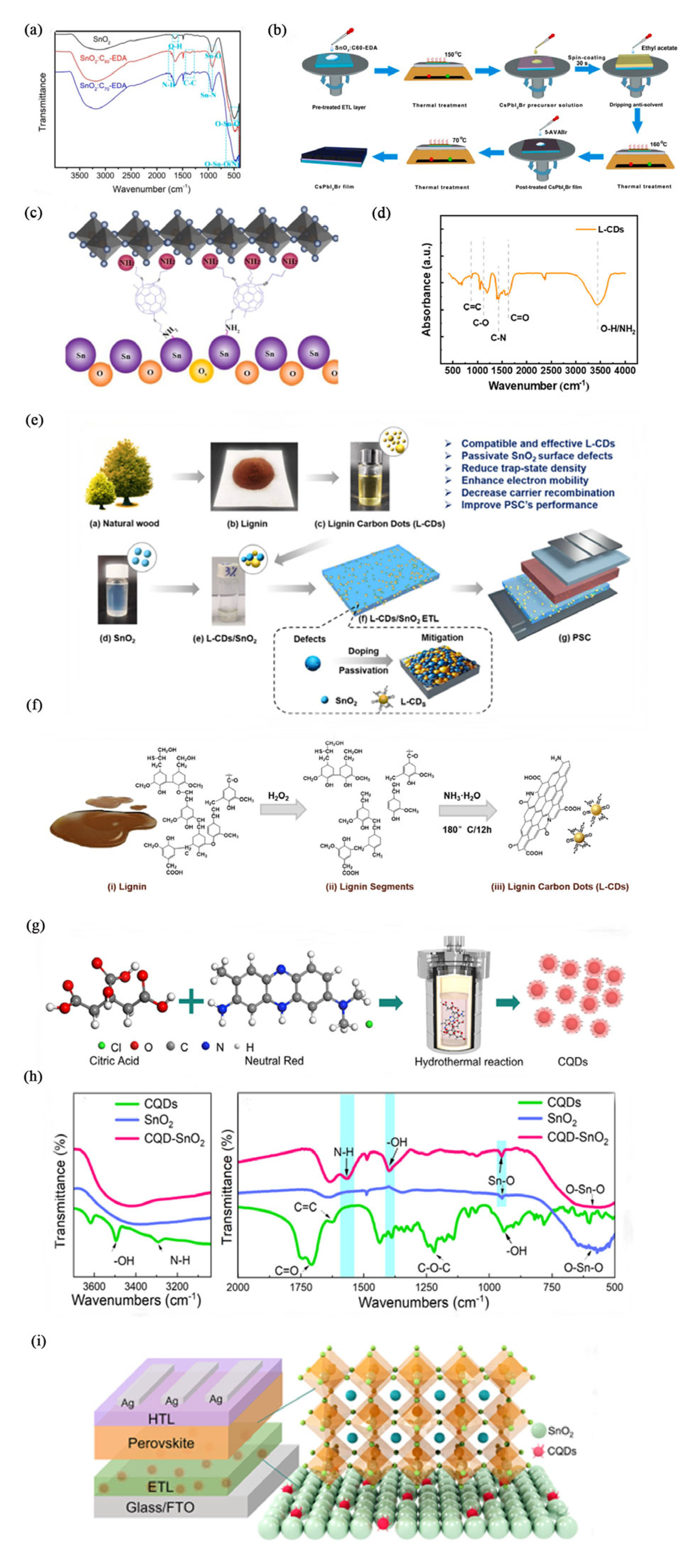
Solid–liquid modification is a technology that enhances the properties of materials by utilizing the interaction between solid materials and liquid reaction media. This process promotes the chemical or physical adsorption of carbon materials with various liquid substances, leading to different performance changes in the carbon materials. However, the liquid reaction substances must possess high permeability and high reactivity. This process enhances the properties of solid materials. Duan and colleagues [67] obtained a SnO2 (Alfa Aesar, 15% in H2O colloidal dispersion, Ward Hill, MA, USA) layer with fullerene–ethylenediamine derivatives (C60-EDA and C70-EDA, in-house preparation) by first completely dissolving fullerene in ethylenediamine. The pre-treatment of the SnO2 layer and the post-treatment of the CsPbI2Br perovskite film with 5-aminopentanoic acid hydrobromide (5-AVABr, in-house preparation) resulted in high photovoltaic and electroluminescent (PV/EL) performance (Figure 2b). Improvements in the film formation characteristics of SnO2: C60-EDA and SnO2: C70-EDA led to the production of CsPbI2Br thin films with lower defect densities and superior interface connectivity, as illustrated in Figure 2a. These combined pre-treatments and post-treatments effectively balance charge transfer at the n-i-p interface for both injection and extraction, thereby achieving efficient inorganic perovskite dual-function devices. Using SnO2: C60-EDA as the ETL enables the formation of a high-quality CsPbI2Br film with complete coverage and large grain sizes. This reduces non-radiative recombination of photo-generated carriers, which enhances both charge extraction and injection, as shown in Figure 2c. Additionally, modifying SnO2 with C60-EDA and C70-EDA significantly improves the Voc and PCE of CsPbI2Br photovoltaic cells.

3.2.2. Hydrothermal Method

The hydrothermal method is a chemical technology used for synthesizing or modifying chemical substances within a closed system. This process creates a reaction environment using a high-temperature hydrothermal reactor, which maintains conditions of high temperature and high pressure. As a result, water can interact with carbon materials in either sub-critical or super-critical states. These interactions result in changes to the properties of the carbon materials. This approach is often employed to modify carbon materials, including CDs [68], CQDs [15], and MWCNTs [69]. For instance, Fang and colleagues [68] dissolved lignin in deionized water, added hydrogen peroxide, stirred the mixture, and then introduced ammonia. They placed the resulting solution in a stainless-steel autoclave lined with polytetrafluoroethylene to prepare Lignin carbon dots (L-CDs, illustrated in Figure 2d, in-house preparation). The inherent aromatic structure and high carbon content of lignin facilitate its direct carbonization into L-CDs (shown in Figure 2e). Lignin was utilized as a precursor to create a liquid crystal material, which helped address the surface defects of SnO2 (Alfa Aesar, 15% in H2O colloidal dispersion, Ward Hill, MA, USA) and enhance the performance of PSCs. The substance acts as both a dopant and a passivator, mitigating defects in SnO2 and improving the performance of PSCs. Due to the good compatibility between SnO2 and L-CDs, along with the abundance of surface groups, the defects in SnO2 can be effectively passivated. This process leads to an 11.8% reduction in trap state density, a 251.7% increase in electron mobility, and a 15.2% increase in PCE (as shown in Figure 2f). Liu et al. [58] synthesized red CQDs (0.5–3.0 nm, in-house preparation) rich in carboxyl and amino groups on their surface through a hydrothermal method (Figure 2g). These synthesized CQDs were introduced as a modifier into SnO2 (Alfa Aesar, 15% in H2O colloidal dispersion, Ward Hill, MA, USA) treated with a low-temperature solution, improving its electrical properties (as shown in Figure 2g–h). This modification also adjusted the interface properties between the ETL and the FAPbI3, embedding the CQDs within SnO2. The CQDs-SnO2 composite enhances the morphology of SnO2, boosts electron mobility, and reduces interface defects. Furthermore, the functional groups on the surface of the CQDs facilitate the crystallization of perovskite into larger grains. Various complex characterizations confirmed these multiple positive effects on interface modulation (see Figure 2i).
Figure 2. (a) Fourier−Transform Infrared Spectroscopy (FTIR) spectra of SnO2, SnO2: C60−EDA, and SnO2: C70−EDA as ETL. (b) Flow chart for preparation of CsPbI2Br films post-treated with different ETL and 5−AVABr. (c) Schematic diagram of the interaction between C60−EDA and SnO2 [67]. Reprinted from ref. [67]. Copyright 2021, American Chemical Society. (d) Infrared Spectroscopy (IR) spectra of modified L−CDs. (e) Preparation and modification of L−CDs for PSCs and passivation of SnO2 were studied. (f) Lignin with inherent aromatic structure and high carbon content is used as a raw material to prepare L−CDs [68]. Reprinted from ref. [68]. Copyright 2025, Elsevier. (g) Schematic diagram of the synthesis process of CQDs. (h) FTIR of CQDs, SnO2, and CQD-SnO2 powders in the ranges of 3100~3700 cm−1 and 500~2000 cm−1. (i) Crystallization mechanism of perovskite thin films grown on SnO2 ETL modified with CQDs [70]. Reprinted from ref. [70]. Copyright 2022, Elsevier.
Sustainability 18 05423 g002

3.2.3. Hummer Method

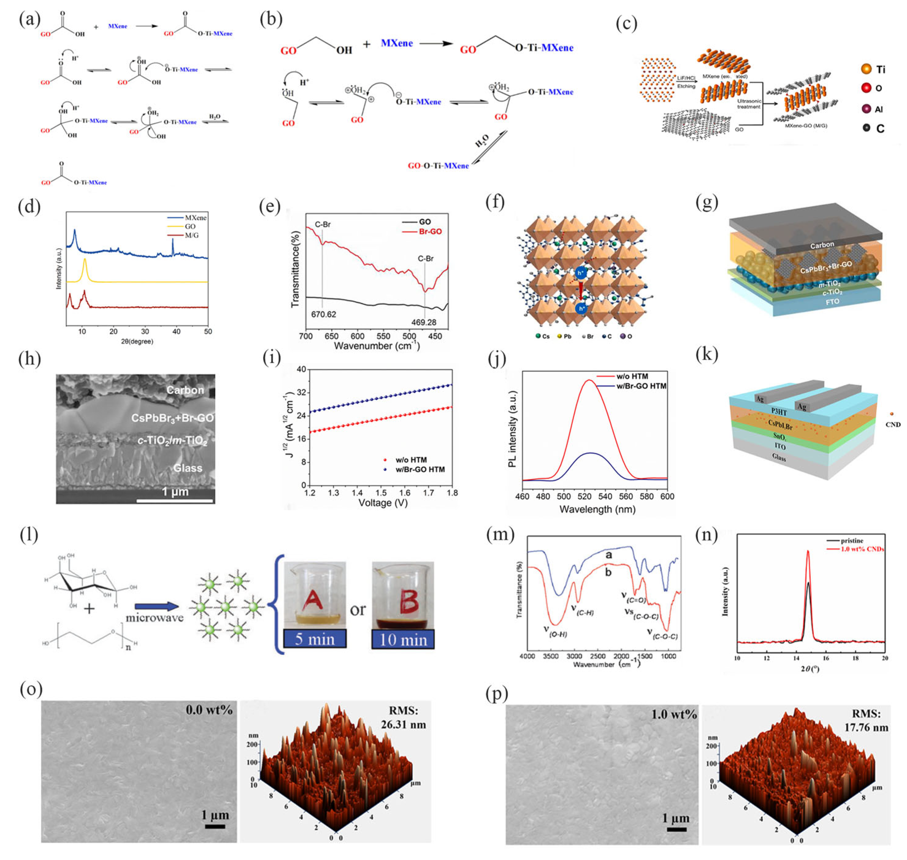
The Hummer Method is a chemical process divided into three main stages: low-temperature embedding, medium-temperature oxidation, and high-temperature hydrolysis. In this process, strong oxidants are utilized to modify graphite, transforming it into GO. The properties of GO can be adjusted by manipulating the conditions during the three stages of the production process. Yao et al. [71] prepared GO (Shanghai MaterWin New Materials Co., Ltd., Shanghai, China) using the Hummer method as follows: graphite powder was added to concentrated nitric acid, followed by the addition of potassium permanganate at a temperature of 20 °C. Once the temperature reached 30 °C, deionized water was added. After allowing the mixture to react for one hour, a large volume of deionized water and hydrogen peroxide was added to the suspension. After this, the suspension was cleaned in order to obtain graphene. Subsequently, Ti2AlC2 (Mianyang Hengyang Electric company, Mianyang, China) powder was stirred into the mixture, resulting in a new 2D Ti3C2Tx MXene-repaired GO heterojunction (as illustrated in Figure 3a,b). The formation of this heterojunction arises from nucleophilic substitution and dehydration reactions between the MXene (Ti-O-) and GO (-C=OH+) (see Figure 3c,d). The oxygen-containing functional groups create a negative charge center, which is stabilized through this interaction. Consequently, this hetero junction not only aligns the energy levels of perovskite and carbon, providing a pathway for carrier transport, but it also effectively stabilizes the soft perovskite lattice. The MXene interacts with oxygen-containing functional groups to eliminate negative centers, effectively contributing to hole transport and passivating film defects. The champion CsPbIBr2 PSC with the M/G treatment achieved a high PCE of 11.1% with a Voc of 1.3 V, while the CsPbI2Br C-PSC achieved an improved PCE of 15.0% with a Voc of 1.3 V. Sun et al. [72] generated GO (Shanghai Mater Win New Materials Co., Ltd., Shanghai, China) using the Hummer method and then modified it via a high-temperature hydrothermal reaction to produce multifunctional brominated GO (as shown in Figure 3e). This modified GO was added to CsPbBr3, successfully delaying the crystallization process and leading to the formation of high-quality perovskite thin films with larger grain sizes (as shown in Figure 3g,h). The Br-GO material has passivated grain boundary defects and neutralized positively charged trap states, resulting in a significant reduction in defect state density and a delay in non-radiative recombination of carriers (as illustrated in Figure 3i,j). The Br-GO, exhibiting strong p-type behavior and a suitable work function, was incorporated into perovskite films, effectively enhancing the performance of CsPbBr3 PSCs. Due to its good work function matching and high hole mobility, the addition of Br-GO notably improved the hole mobility in the CsPbBr3@Br-GO photoactive layer. This enhancement facilitated better charge separation and transfer while suppressing the radiative recombination of carriers.
Figure 3. (a,b) Reaction mechanism of GO and Mxene. (c) Schematic diagram of M/G heterojunction forming a Ti−O−C bond. (d) X−ray Diffraction (XRD) of Mxene, GO, M/G. FTIR spectra of (e) GO and Br−GO [71]. Reprinted from ref. [71]. Copyright 2023, Elsevier. (f) Crystal structure diagram of perovskite after Br−GO addition. (g) Structure diagram of Br−GO modified to the perovskite layer and (h) Scanning Electron Microscope (SEM) section. (i) Dark J1/2−V curves of FTO/NiO/CsPbBr3@Br−GO/HTM with or without Br−GO/Carbon. (j) Photoluminescence Spectroscopy (PL) spectra and Time−Resolved Photoluminescence Spectroscopy (TRPL) attenuation spectra of CsPbBr3@Br-GO deposited on TiO2 layers with or without Br−GO HTM [72]. Reprinted from ref. [72]. Copyright 2021, Elsevier. (k) Schematic diagram of CNPs modified into the perovskite layer. (l) Microwave pyrolysis of CNPs. (m) FTIR spectra of sample a (microwave-assisted 5 min), sample b (microwave-assisted 5 min). (n) Comparison of the (100) peak of the original CsPbI2Br thin film and the CsPbI2Br thin film modified with 1.0 wt% Cd. (o) SEM (left) and atomic force microscope (AFM) (right) images of unmodificated CsPbI2Br films and (p) modified 1.0 wt% CNDs on ITO glass [73]. Reprinted from ref. [73]. Copyright 2022, Elsevier.
Sustainability 18 05423 g003

3.2.4. Microwave-Assisted Method

The microwave-assisted method is an enhanced technique that uses microwave radiation to accelerate the modification reactions of carbon materials. Wang et al. [73] dispersed CA and urea in deionized water and reacted them in a microwave oven. Afterward, they dissolved the mixture in ethanol and obtained CNDs (in-house preparation) via centrifugation, as illustrated in Figure 3l,m. When CNDs are appropriately introduced (shown in Figure 3k), the defect density and surface roughness of the CsPbI2Br layer are reduced, resulting in enhanced crystallinity and moisture resistance. This enhancement can significantly lower trap density and enhance the overall crystallinity of the material, as demonstrated in Figure 3n–p.

3.2.5. Solvthermal Process

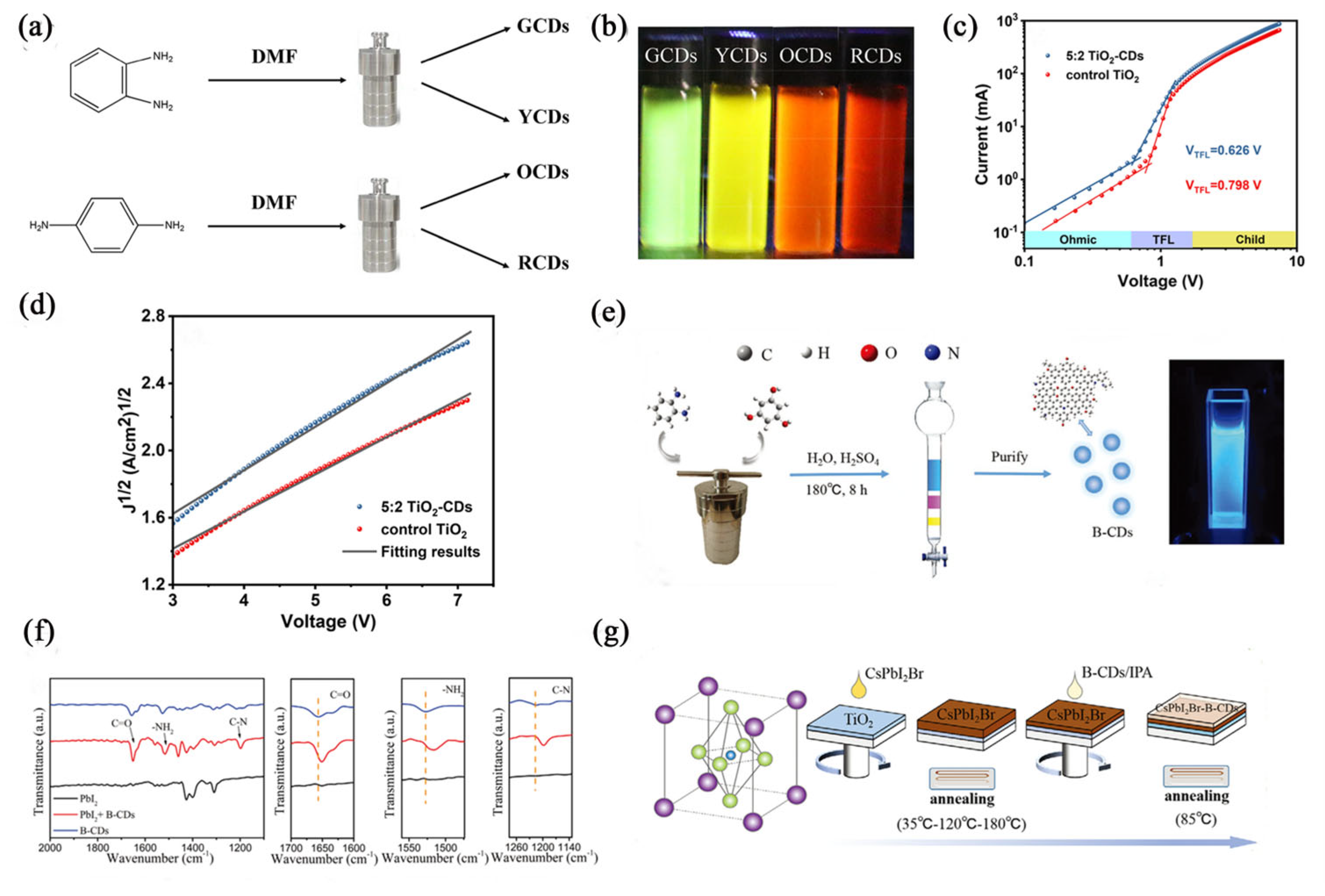
The solvothermal process is a chemical technique used to modify carbon materials by applying specific thermodynamic and kinetic conditions within a sealed, high-temperature system. When different solvents, which are characterized by low viscosity, high diffusivity, and strong solubility, are added to the carbon materials under supercritical or subcritical conditions, the types and concentrations of functional groups on the carbon materials can change. These alterations depend on the types of solvents used and the duration of the reactions. For instance, Huo et al. [74] dispersed p-phenylenediamine in DMF to create a solution (as illustrated in Figure 4a,b). This solution was then subjected to a high-temperature reaction inside a PTFE-lined stainless-steel autoclave, resulting in the dispersion of CQDs (in-house preparation). When the TiO2-CD dispersion is spin-coated onto a dense layer of C-TiO2, an appropriate amount of CdS can significantly reduce electron recombination at the interface. The TiO2-CdS layer enhances the lattice growth of the subsequent perovskite and effectively facilitates the extraction of electrons from the perovskite to TiO2. Notably, the electron mobility of TiO2 increases from 3.0 × 10⁻⁵ to 4.1 × 10⁻⁵ cm2·V−1·s−1 as a result of incorporating CDs, as shown in Figure 4c,d. Gu et al. [18] prepared B-CD (in-house preparation) powder by dispersing o-phenylenediamine and phloroglucinol in ultrapure water. They mixed this solution with concentrated nitric acid in a polytetrafluoroethylene-lined autoclave. After the reaction was complete, they adjusted the pH and obtained the material through silica gel column chromatography (as shown in Figure 4e). The functionalized B-CD was proposed as an interface passivation layer (Figure 4g) to enhance the efficiency and long-term stability of all-inorganic CsPbI2Br PSCs. The study found several key benefits of using these blue CQDs. First, the B-CD, which contains abundant N-H, C-N, C-O, and C=O functional groups, effectively passivates defects by forming hydrogen bonds and coordination bonds with I and Pb2+ ions in the perovskite. Second, the p-type B-CD modifiers form P-N junctions with n-type perovskites, creating efficient pathways for hole transfer while blocking electrons. Finally, the incorporation of B-CD increases the hydrophobicity of the perovskite film, thereby enhancing the stability of CsPbI2Br PSCs (Figure 4f).
Figure 4. (a) Schematic diagram of CDs synthesis, starting materials: p-phenylenediamine, o-phenylenediamine, N, N−dimethylformamide. (b) Photographs of four samples under ultraviolet light [74]. Reprinted from ref. [74]. Copyright 2018, Elsevier. (c,d) Dark current−voltage characteristic curves of PSCs containing control TiO2 and TiO2−CDs [18]. Reprinted from ref. [18]. Copyright 2023, Elsevier. (e) Preparation of B−CDs. (f) FTIR spectra of PbI2 and B−CDs solutions with and without PbI2 addition. (g) Preparation of CsPbI2Br−B−CDs thin films [75]. Reprinted from ref. [75]. Copyright 2021, Wiley−VCH.
Sustainability 18 05423 g004

3.2.6. Electrospinning

Electrospinning is an advanced technology that utilizes an electric field to create micro- and CNFs. This process works by applying a high voltage to overcome the surface tension of a polymer solution or melt. As a result, an electrically charged jet is produced, which is then stretched and swirled. This stretching causes the solvent in the solution to evaporate or the melt to solidify under the influence of the electric field, ultimately forming CNFs. Changing the type of polymer solution or melt will produce different CNFs, and by altering these solutions or melts, it is possible to modify the properties of the resulting CNFs. In a study conducted by Xu et al. [17], an electrospinning solution was prepared using PAN (Tianjin Heowns Corp, Tianjin, China) in DMF. The researchers established specific conditions for electrospinning to produce polymer fibers, which were then subjected to a two-step high-temperature treatment in a tubular furnace. This process involved pre-oxidation at 250 °C for 60 min, followed by a gradual increase to 800 °C at a rate of 5 °C/min in a nitrogen atmosphere for another 60 min, resulting in N-CNFs. When these N-CNFs, enriched with nitrogen-containing functional groups, were incorporated into perovskite films, they provided numerous nucleation sites and fibrous templates. This incorporation facilitated preferential crystal orientation growth and reduced defect density within the films. Another study by Batmunkh et al. [76] focused on preparing TiO2 CNFs (in-house preparation) through electrospinning a sol–gel solution. This solution comprised titanium (IV) n-butoxide (TIB, 5.0 g), polyvinyl pyrrolidone (PVP, 1.0 g), and glacial acetic acid (1 mL) dissolved in ethanol (10 mL). Their research explored the impact of CNTs on the photovoltaic performance of PSCs that utilized 1D TiO2 NF photoelectrodes.

4. Modifying PSCs with Carbon Materials

The typical structure of PSCs comprises five primary functional layers. Multiple factors influence the PCE of PSCs. Material modifications encompass a charge transport layer, a perovskite light absorption layer, an interface layer positioned between the charge transport layer and the perovskite light absorption layer, a second interface layer situated between the perovskite light absorption layer and the carbon electrode, as well as the electrode itself. These modifications serve to enhance overall device performance. During the doping modification of carbon materials in PSCs, certain carbon candidates are intrinsically limited by their solubility characteristics and can only be formulated into low-concentration colloidal dispersions. Carbon materials with favorable solubility are capable of high-concentration doping to modulate and optimize the optoelectronic performance of PSCs; meanwhile, they have also been directly utilized as HTLs in relevant research. In comparison, carbon materials with inferior solubility can be applied as carbon counter electrodes, and can also be engineered as interfacial interlayers inserted between the HTL and carbon electrode. This chapter focuses specifically on charge transport layers, perovskite light absorption layers, and carbon materials employed as interface layers, while excluding those carbon materials utilized in electrodes.

4.1. Modification of the Charge Transport Layer

In recent years, the PCE of metal halide PSCs has seen significant advancement. Improving the PCE of wide-bandgap PSCs is particularly challenging due to non-radiative recombination [66]. To reduce non-radiative recombination, it is essential to achieve optimal interface and energy-level alignment at the absorption interface of the transport layer [77].
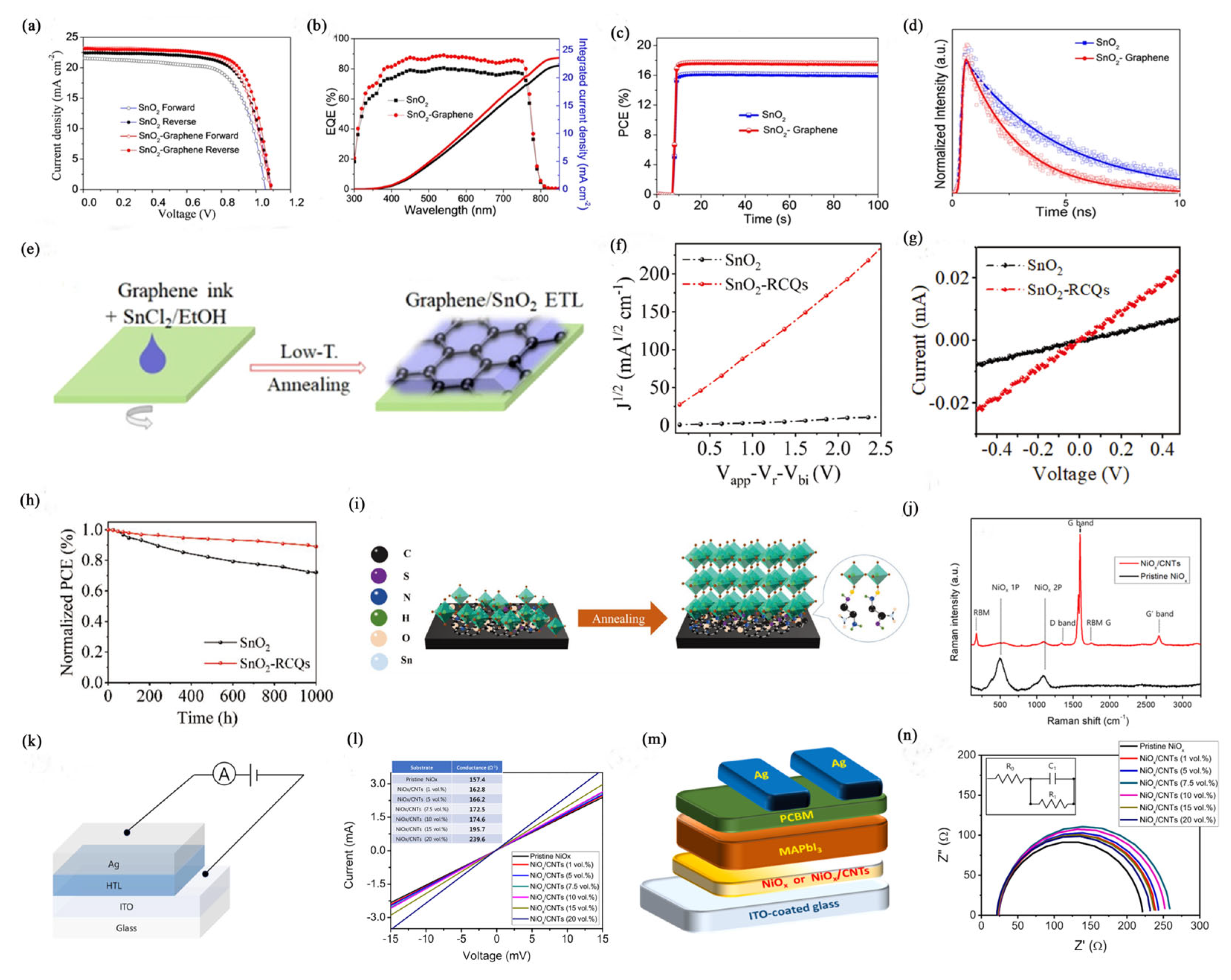
Although strategies such as grain boundary passivation, surface post-treatment, and process management can enhance the stability of PSCs, many PSCs still face a significant hysteresis issue [70,78]. The main causes of hysteresis in PSCs are charge-carrier trapping and detrapping, slow capacitance response, and band bending from ion migration [60,78]. Researchers have already studied ways to enhance the performance of PSCs by improving the charge transport layer (see Table 2). For instance, Zhu et al. [70] incorporated graphene (in-house preparation) into SnO2 (in-house preparation), as illustrated in Figure 5e. This approach significantly enhances electron extraction efficiency, leading to reduced charge recombination at the interface between the ETL and the perovskite. As a result, the PCE exceeds 18.0% (refer to Figure 5a–d), and the hysteresis index decreases from 0.08 to 0.02, making the hysteresis nearly negligible.
The charge transfer layer is a crucial functional component of PSCs, and its properties significantly impact the photovoltaic performance of these cells [67,79]. Inefficient charge transfer within the charge transport layer can reduce electron extraction from the perovskite light-absorbing layer, leading to degradation of the perovskite and increased charge recombination [80,81]. Carbon materials serve as additives in the charge transfer layer of PSCs, which enhances the charge collection pathways and accelerates electron extraction at the interface [82,83]. In a study by Hui et al. [77] SnO2 (Alfa Aesar, 15% in H2O colloidal dispersion, Ward Hill, MA, USA) was doped with red CQDs (in-house preparation) rich in carboxyl and hydroxyl groups through a temperature treatment (Figure 5i). This doping resulted in an increase in electron mobility from 9.3 × 10⁻⁴ to 1.7 × 10⁻² cm2·V−1·s−1, representing a 20-fold improvement (Figure 5f,g). Additionally, the PCE improved significantly, rising from 19.2% to 22.8%. The devices also demonstrated excellent stability in humidity conditions ranging from 40% to 60% (illustrated in Figure 5h).
The performance of PSCs is influenced by the conductivity of the charge transport layers and the energy level alignment within the device [41,84]. The HTL is critical for improving PSC performance [58]. Metal oxides, which are often used as hole-transporting layers, generally exhibit insufficient conductivity, resulting in increased series resistance and a reduced FF [54,85,86]. To mitigate this limitation, researchers have modified these materials with elements such as cobalt, Cs, Li, Cu, and Ag to enhance conductivity. High conductivity is crucial as it enhances charge extraction and carrier mobility while suppressing defect-mediated recombination of photogenerated carriers [87]. For instance, Ryu et al. [55] developed a composite HTL utilizing NiOx (in-house preparation) combined with CNTs (semiconducting single-wall CNT, diameter range of 1.2–1.7 nm, length range of 300 nm to 5 μm, NanoIntergris, Evanston, IL, USA), systematically varying the CNT content from 0 to 20 vol% (Figure 5j). This modification significantly improved both conductivity (Figure 5k,l) and charge extraction performance (Figure 5m,n). Consequently, the average PCE of the PSCs increased substantially from 3.1% to 15.1%, with a maximum recorded PCE of 16.9%.
Figure 5. (a) J−V curves of optimal PSCs in forward and reverse directions for SnO2 and SnO2−graphene prepared PSCs. (b) External Quantum Efficiency (EQE) spectra for optimal cell performance. (c) Stable PCE measured as a function of time at Vmpp of 0.925 V and 0.872 V. (d) Normalized TRPL response of perovskite thin films. (e) Preparation process of ETL based on SnO2−graphene [70]. Reprinted from ref. [70]. Copyright 2018, American Chemical Society. (f) J−V characteristics of pure electronic devices based on SnO2−RCQs and SnO2 ETL. (g) Conductivity of SnO2 and SnO2−RCQs prepared thin films. (h) Normalized PCE as a function of time for PSCs prepared based on SnO2 and SnO2−RCQs in a dark environment at a relative humidity of 40−60% and a temperature of 25 °C [77]. Reprinted from ref. [77]. Copyright 2019, Wiley−VCH. (i) Crystallization mechanism of perovskite thin films prepared on SnO2-RCQs as ETL. (j) Raman spectra of NiOx and NiOx/CNT hybrids prepared on white glass. (k) Schematic diagram of conductivity measurement. (l) Conductivity of hybrid materials with different CNT content (0−20 vol%). (m) Schematic diagram of inverted planar PSCs. (n) Nyquist diagram of different perovskite devices with NiOx and NiOx/CNTs mixed layers as HTL [57]. Reprinted from ref. [57]. Copyright 2020, Elsevier.
Sustainability 18 05423 g005
The charge transport layer is primarily prepared using the solution spin coating method. However, this method often results in a layer that is relatively thin and uneven, which can lead to the formation of pinholes and significant surface roughness [82,88]. These defects are detrimental to the performance of PSCs. Pinhole defects in the charge transport layer can degrade the perovskite absorption layer, ultimately reducing the efficiency of the PSCs [89,90]. Poor surface morphology of the thin film can adversely affect the deposition of subsequent thin film layers, further impairing PSC performance. Lu et al. [91] have addressed this issue by introducing graphene quantum dots (GQDs, Suzhou Tanfeng Graphene Technology Co., Ltd., Suzhou, China) into SnO2 (Alfa Aesar, 15% in H2O colloidal dispersion, Ward Hill, MA, USA). This approach effectively enhances the morphology of SnO2 thin films, improves conductivity, promotes electron transfer, reduces surface roughness, and increases ohmic contact between the SnO2 and perovskite layers.
Table 2. The use of modified carbon materials in the charge transport layers.
StructureJSC
(mA/cm2)
VOC
(V)
FF
(%)
PCE
(%)
TypeRefs.
FTO/compact-TiO2/TiO2-CDs/FA0.85MA0.15Pb(I0.85Br0.15)3/PCBM/Ag26.01.270.021.1CDs[18]
ITO/NiOx/Me-4PCAZ/Cs0.04(FA0.95MA0.05)0.96Pb(I0.95Br0.05)3/tBu-FIDO/BCP/Ag24.81.278.322.1Indanones
(tBu-FIDO)
[48]
FTO/b-TiO2/TiO2@r-GO/CH3NH3PbI3/Spiro-OMeTAD/Ag22.00.970.714.5GO/Mesoporous TiO2[52]
ITO/SnO2@GQDs/CH3NH3PbI3/Spiro-OMeTAD/Au23.01.175.419.7GQDs[54]
ITO/NiOx@CNTs/MAPbI3/PCBM/Ag22.01.075.916.9CNT[55]
FTO/SnO2/CQD-SnO2/FAPbI3/Spiro-OMeTAD/Ag25.61.281.224.1CQDs[58]
FTO/TiO2/CsPbI2Br/P3HT/CNT/C14.61.478.515.6CNTs/poly(3-hexylthiophene)[60]
ITO/SnO2@C60-EDA/CsPbI2Br/5-AVABr/Spiro-OMeTAD/MoO3/Ag15.41.380.316.6C60-EDA[67]
Ag/L-CDs@SnO2/Perovskite/Spiro-OMeTAD/Ag23.81.181.320.9L-CDs[68]
FTO/Graphene@SnO2/MAPbI3/Spiro-OMeTAD/Au23.11.172.018.1graphene−
SnO2
[70]
FTO/cp-TiO2@SWCNTs/CH3NH3PbI3/Spiro-OMeTAD/Au21.41.067.014.0Single-Walled (SWCNT)/TiO2[76]
ITO/SnO2@RCQs/Cs0.05FA0.81MA0.14PbI2.55Br0.45/Spiro-OMeTAD/MoOX/Au24.11.182.922.8red-CQDs (RCQs)
functionalized NiOx
[77]
FTO/TiO2/FA0.83Cs0.17PbI2.5Br0.5/f-NiOx+CNT/C18.30.664.011.4(f-NiOx) and CNT (f-NiOx + CNT)[80]
FTO/c-TiO2/m-TiO2/CsPbBr3/MoO2@
/N-doped carbon nanospheres composites)/carbon
7.21.585.29.4MoO2/N-
doped NC
[82]
FTO/SnO2/@CQDs/FAMA0.2Pb1.1I2.2Br0.6/Sprio-OMeTAD/Ag21.61.178.018.6SnO2: GQDs[91]
FTO/GQDs@TiO2NRs/Csx(MA0.17FA0.83)(1−x)Pb(I0.83Br0.17)3/Spiro-OMeTAD/Au22.10.864.011.7GQDs-TiO2 NRs[92]
ITO/PTAA/MAPb(I0.8Br0.2)3/PCBM@ICBA/BCP/Ag17.61.481.218.9ICBA[93]
FTO/PEDOT:PSS/CH3NH3PbI3/PC61BM@C60/Ag23.01.078.017.5C60 doped PC61BM[94]
FTO/TiO2:CNDs/CH3NH3PbI3/Spiro-OMeTAD/Au23.31.175.219.5TiO2/carbon nanodots (CNDs)[95]
ITO/SnO2@NDI-Graphene/FA0.75MA0.15Cs0.1PbI2.65Br0.35/Spiro-OMeTAD/Au22.71.182.120.22D naphthalene diimide-[96]
ITO/NiO@CQD/CH3NH3PbI3/PCBM/BCP/Ag20.21.177.216.9incorporating CQDs into a NiOx[97]
FTO/MWCNT/TiO2/CH3NH3PbI3/Spiro-OMeTAD/Au28.01.173.321.4MWCNT[98]
FTO/NiOX/MAPbI3/C60@PMME/BCP/Ag22.21.079.618.4Fullerene-bis (pyridin-2-ylmethyl) malonate[99]

4.2. Modified Perovskite Layer with Carbon Materials

To improve the PCE of PSCs, it is essential to reduce defects in the perovskite films. Achieving uniform, pinhole-free, and large-grain perovskite films can minimize the number of grain boundaries, which in turn increases charge mobility [73,100,101]. Fewer grain boundaries help inhibit charge recombination, leading to enhanced PCE and greater environmental stability of the solar cells. Researchers are currently investigating ways to enhance the perovskite layer by incorporating carbon materials. For more details, please refer to Table 3.
According to the theory of crystallization kinetics, introducing multifunctional additives into the precursor solution of a perovskite optical absorption layer can effectively adjust the crystallization process of perovskite crystal grains and passivate uncoordinated ion defects [102,103]. This leads to the preparation of perovskite films with improved quality and fewer defect states. Carbon materials can serve as additives that modify the chemical and electronic properties of perovskite, allowing for the production of larger grain sizes and fewer grain boundaries, which in turn reduces carrier recombination at those boundaries [20,114]. Research conducted by Ma et al. [59] indicates that modifying the perovskite layer with three different types of CNTs (as shown in Figure 6a) can enhance crystallization. Specifically, the use of COOH-NH2 promotes improved crystallization of the perovskite film. Compared to the original modification with CNTs (in-house preparation), incorporating COOH-CNTs into the perovskite film has resulted in a tenfold increase in hole mobility. This shows that functional groups on carbon materials play a crucial role in regulating the nucleation and growth of perovskite thin films (as shown in Figure 6b). By adjusting the functional groups on the CNTs, stable perovskite films can be produced with low defect density, high quality, and enhanced stability. Additionally, CNTs can effectively improve carrier transport performance in perovskite films, thereby increasing the PCE of PSCs (as shown in Figure 6c). Furthermore, Gong et al. [104] observed that by adding black phosphor quantum dots (BPQDs, in-house preparation) to the perovskite precursor solution, significant improvements in crystallization and morphology occur. BPQDs can act as seed-like sites that regulate the nucleation and growth of perovskite crystals. The lone pair of electrons in BPQDs reduces the Coulomb repulsion between the molecules of the perovskite precursor solution and phosphorus atoms. Additionally, the BPQDs/CsPbI2Br core–shell structure enhances the stability of the perovskite crystals and inhibits the oxidation of the BPQDs.
Carbon materials have been integrated into perovskite layers or interfacial layers due to their excellent photoelectric properties, suitable optical band gap, environmental friendliness, low cost, and controllable size [105]. In the perovskite light-absorbing layer, the incorporation of carbon-based additives can help improve performance, but they cannot eliminate the adverse effects on the device [53]. This limitation arises from the relatively low number of oxygen-containing groups present in the carbon materials, leading to weak passivation of ionic defects in the perovskite film [73]. Chemical modification of carbon materials with specific functional groups and halogen elements exerts positive effects on perovskite light-absorbing layers and PSCs. Zhu and colleagues [15] utilized Br-CQDs (in-house preparation) as additives and for buried interface modification to enhance perovskite film quality. The Br-CQDs (in-house preparation), which include both bromine and oxygen groups, can interact with uncoordinated Pb2+ and Cs+ ions. By embedding within the perovskite lattice, these CQDs act as a “binder”, helping to reduce charge recombination and energy loss within the perovskite absorption layer (Figure 6d). This improvement is attributed to the effective delay of the nucleation and growth process, the repair of trap states in the perovskite film, the reduction in lattice strain, and the adjustment of interface energy levels (Figure 6e). Carbon materials can have a beneficial impact on perovskite layers and photovoltaic cells through their modification. This enhancement arises from their ability to introduce functional groups, such as hydroxyl, carboxyl, and epoxy groups. Research has demonstrated that modifying perovskite with carbon materials can promote crystallization, facilitate charge extraction, inhibit ion migration, reduce hysteresis phenomena, and improve environmental stability.

4.3. Carbon Materials as Surface Modifiers

PSCs now feature a sandwich structure, which consists of a light-absorbing perovskite layer situated between an electron-transporting layer and a hole-transporting layer [113,115,116,117]. In this configuration, the buried interface between the perovskite layer and the charge transport layers is crucial for both the PCE and the stability of the PSCs [61]. Despite the implementation of various strategies to enhance the stability of PSCs—such as grain boundary passivation, surface post-treatment, and improved process management—the overall operational stability remains inadequate [53]. This is primarily due to the insufficient attention given to the interface contact between the charge transport layers and the perovskite light-absorbing layer.
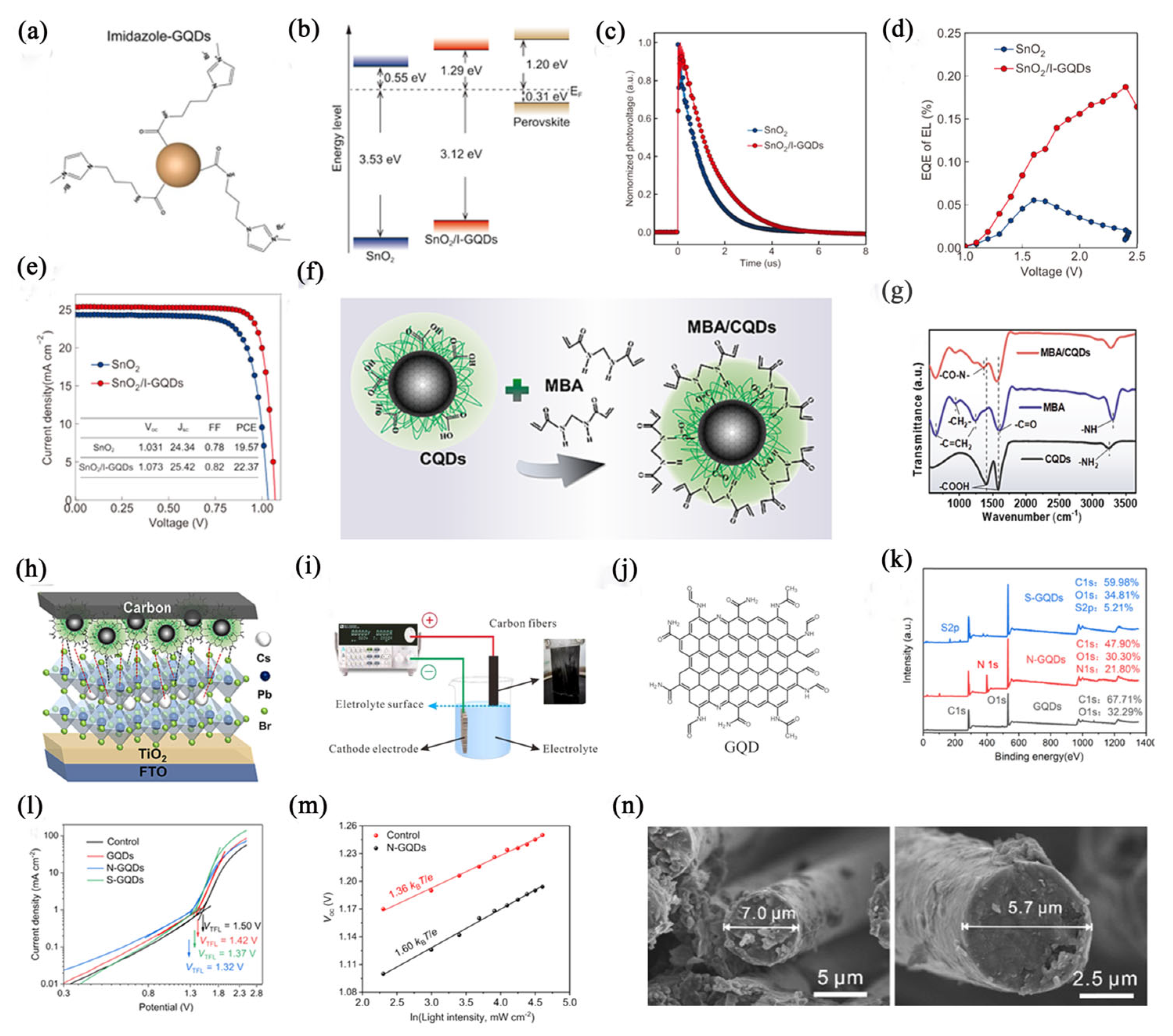
This concealed interface not only impacts the extraction of electrons from the ETL and the collection of photons from the HTL, but it also affects the quality of the perovskite crystal and the formation of trap states [71]. Incomplete connections at the interface can negatively influence the performance of PSCs, resulting in hysteresis effects, decreased PCE, and reduced environmental stability [118]. While buried interfaces are often implemented to minimize interface defects, achieving effective molecular design that provides excellent charge transport and defect passivation capabilities remains a significant challenge. Researchers have conducted thorough studies on this topic, and the findings are summarized in Table 4. Gao et al. [119] introduced imidazole bromide functionalized graphene quantum dots (I-GQDs, Nanjing XFNANO Materials Tech Co., Ltd., Nanjing, China) (Figure 7a) as the interface between the ETL and the lead formamidine iodide (FAPbI3) perovskite layer. The multifunctional groups on the surface of the GQDs help reduce interface trap states, promote the formation of high-quality perovskite films, and decrease non-radiative recombination. This improves the overall quality and stability of PSCs while inhibiting non-radiative recombination. The incorporation of I-GQDs improves the conductivity of the SnO2 (Alfa Aesar, 15% in H2O colloidal dispersion, Ward Hill, MA, USA) ETL, eliminates surface defects, achieves better conduction band alignment to enhance carrier transport (Figure 7b,d), and suppresses interface charge recombination to minimize voltage loss (Figure 7c). As a result, n-i-p FAPbI3 PSCs with I-GQD modulation achieve a high efficiency of 22.4% and demonstrate enhanced long-term stability. Wang et al. [49] achieved a PCE of 10.4% for carbon-based CsPsBr3 photovoltaic devices by using a post-treatment interface modification method involving MBA/CQD (in-house preparation). This process, illustrated in Figure 7f, involved a dehydration condensation reaction between the carboxyl groups on the surface of the CQDs and the amino groups in MBA, as shown in Figure 7g. This reaction reduces the edge defects of CQDs and lowers their oxygen content. Additionally, the functionalization of the MBA molecules increases the sp2 hybrid carbon content in the CQDs and enhances carrier transport behavior, thereby minimizing the edge defects. The modified MBA/CQDs also create an intermediate energy level at the interface between the perovskite and the carbon back electrode. This facilitates better charge extraction and reduces energy loss. Overall, MBA/CQDs modify the interfaces of perovskite films, thereby suppressing the cation and anion defects. These modifications optimize the energy band structure between the perovskite layer and the carbon electrode, as depicted in Figure 7h, which leads to improved hole extraction, reduced charge recombination, and decreased energy loss.
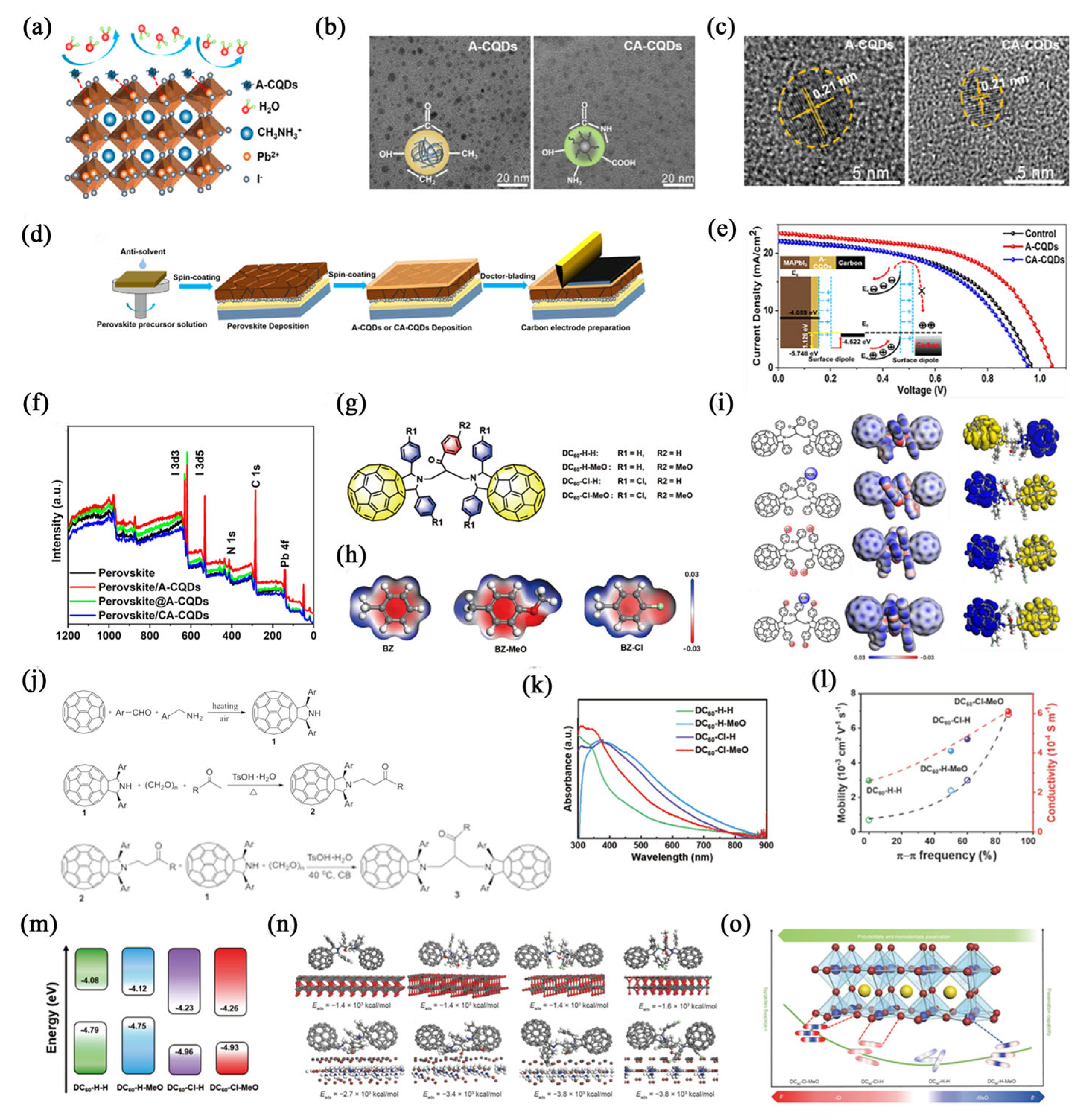
Improving the performance of solar cells relies heavily on two key factors: effective charge extraction at interfaces and suppression of charge recombination [51]. In addition to passivating non-radiative recombination traps, enhancing the charge extraction and transport rates across perovskite grains is crucial [49]. This type of interface modification can effectively reduce issues such as poor conductivity and inadequate light stability of the perovskite layer. Interface engineering plays a vital role in adjusting the properties of the interface, passivating surface defects in perovskite thin films, promoting charge extraction, and preventing moisture intrusion [120]. Together, these strategies contribute to enhancing the PCE and the long-term stability of PSCs. Energy loss at the interface can occur due to several factors, including energy level mismatches, non-intimate contacts, and interface defects [65]. These issues can lead to specific charge distribution imbalances and high charge accumulation, ultimately resulting in performance degradation of the PSCs. Hysteresis and stability losses are often associated with energy barriers and carrier recombination at the interface. Thus, effective charge extraction at the interface is critical for maximizing the performance of PSCs. Zhou et al. [51] can improve the quality of the perovskite film and significantly reduce harmful non-radiative recombination by adding N or S atoms (Figure 7i) to Pb2+ defects located on the surface of the perovskite film due to the interaction between GQDs (24 K, 7.0 µm fiber diameter, Toray T700SC of Japan, Tokyo, Japan) (Figure 7n) and uncoordinated Pb2+ based on Lewis’s acid-base chemistry. In addition, the energy levels of GQDs are modulated. Meanwhile, the energy levels of GQDs were modulated. N-/S-doped GQDs (Figure 7j) acted as an interfacial mediator (Figure 7k) to passivate defect sites and facilitate charge extraction (Figure 7l,m). Tang et al. [119] passivated the CH3NH3PbI3 surface (Figure 7d) by using carbon quanta with functional groups (A-CQDs, Nanjing XFNANO Materials Tech Co., Ltd., Nanjing, China), containing -OH, -CO, -CH3, and -CH2- groups (Figure 7b,c). The carbonyl group of A-CQDs positively interacts with the non-coordinating Pb2+ on the perovskite film (as shown in Figure 7a), promoting the crystallinity enhancement and defect density reduction in the A-CQD-passivated perovskite film. Compared with pure perovskite and MAPbI3/CA-CQDs thin films, the modified films exhibit superior charge transfer characteristics, and the average carrier lifetime τavg is significantly prolonged (Figure 7f). The passivation layer of A-CQDs reduces the energy mismatch between the MAPbI3 film and the carbon electrode, and can effectively transport selective carriers. The introduction of an A-CQDs passivation layer not only forms large grains, reduces the defect density of the perovskite film, but also adjusts the energy level matching between the perovskite film and carbon electrode well, thus promoting efficient carrier transport (Figure 7e).
Figure 7. (a) Structural diagram of I−GQDs. (b) Energy−level diagrams of SnO2, SnO2/I−GQDs, and perovskite layers. (c) Normalized transient photovoltage decay curves of PSCs with different structures prepared by SnO2 and SnO2/I−GQDs. (d) EQE of LEDs prepared by SnO2 and SnO2/I-GQDs, respectively [119]. Reprinted from ref. [119]. Copyright 2021, American Chemical Society. (e) Reverse scanning J−V curves of PSCs prepared by SnO2 and SnO2/I−GQDs. (f) Schematic diagram of MBA functionalized CQDs. (g) FTIR of CQDs, MBA, and MBA/CQDs. (h) Schematic diagram of carbon−based CsPbBr3 PSCs prepared using MBA/CQDs [50]. Reprinted from ref. [50]. Copyright 2024, Elsevier. (i) Experimental setup diagram of GQDs prepared by the solid−liquid interface stripping technique. (j) Structure diagram of GQDs. (k) X−ray Photoelectron Spectroscopy (XPS) spectra of GQDs. (l) Dark J-V curves of FTO/CsPbIBr2/GQDs/Ag devices. (m) Voc as a function of illumination intensity of controlled and N-GQDs customized devices. (n) Scanning electron microscope (SEM) images of carbon fiber raw materials and carbon fibers after electrolysis for 5 min [51]. Reprinted from ref. [51]. Copyright 2022, Elsevier.
Sustainability 18 05423 g007
Incorporating carbon-based materials into the perovskite light-absorbing layer can mitigate moisture-induced degradation, thereby enhancing the humidity stability of PSCs [51]. However, the significantly lower conductivity of these polymers compared to the perovskite can impede charge transport within the perovskite lattice [119]. This impediment may lead to reduced photocurrent and diminished PCE of the PSCs. Furthermore, insufficient charge extraction can lead to charge accumulation, causing hysteresis and consequent operational instability of the PSCs. Wang et al. [121] synthesized four novel fullerene dimers, designated DC60-R1-R2 (where R1 = H or Cl; R2 = H or MeO, in-house preparation), serving as intermediate layers between metal oxides and perovskites (Figure 8g–j). Research revealed that the polar substituents of these dimers significantly influence their intermolecular interactions (Figure 8l). Among them, DC60-Cl-MeO exhibited superior intermolecular charge transfer and passivation capabilities, due to the significant push–pull effect generated by the electron-accepting Cl and MeO groups (Figure 8k). In a planar heterojunction configuration, unencapsulated (FAPbI3)x(MAPbBr3)1−x PSCs utilizing DC60-Cl-MeO as the interlayer achieved a maximum PCE of 23.3%. Additionally, a series of PSCs with enhanced sandwich structures was developed by incorporating push–pull functionalized substituents into the fullerene dimer (Figure 8m). The augmented dipole–dipole intermolecular interactions from these substituents not only optimize the π-stacking configuration (Figure 8l) but also enhance the passivation efficacy of the fullerene dimer. This enhancement facilitates efficient electron extraction and minimizes interfacial recombination losses in the PSC (Figure 8n,o).
Figure 8. (a) The interaction mechanism of A−CQDs with MAPbI3 films. (b) Transmission Electron Microscope (TEM) images of A−CQDs and CA−CQDs, scale size 20 nm. (c) The proportional size is 5 nm. (d) Process diagram for preparing C−PSCs by surface passivation of CQDs. (e) Performance comparison of PSCs prepared by A−CQDs and CA−CQDs. (f) High-resolution XPS spectra of control perovskites, MAPbI3/CA−CQDs (0.2 mg/mL), perovskite/A−CQDs (0.5 mg/mL), and perovskite @A-CQDs (0.1 wt%): full measurement spectra [113]. Reprinted from ref. [113]. Copyright 2021, American Chemical Society. (g) Chemical structure of fullerene dimer DC60−R1−R2 with different substituents. (h) ESP distribution of substituents. (i) Chemical structure of fullerene dimer (left), Density Functional Theory (DFT) results of ESP (center), HOMO electrons (yellow part on right), and LUMO electrons (blue part on right). (j) Preparation process. (k) Ultraviolet−visible absorption spectra of fullerene dimer. (l) Changes in the conductivity and mobility of fullerene dimer with π −π stacking frequency. (m) Energy levels of fullerene dimer calculated from DFT simulations. (n) DFT simulation of adsorption configurations and adsorption energies (Eabs) of different fullerene dimers on SnO2. (o) Schematic diagram of π−π stacking and passivation ability of fullerene dimer [121]. Reprinted from ref. [121]. Copyright 2023, Springer.
Sustainability 18 05423 g008
Defective interfacial contacts adversely affect the performance of PSCs by inducing hysteresis, diminishing PCE, and compromising operational stability. To improve the interface properties between the perovskite light-absorbing layer and the charge transport layer or the electrode, carbon materials are integrated into this interfacial region [75]. This modification enhances the crystallization and functionality of the contact layers, optimizes energy band alignment, and facilitates improved energy level matching.
Table 4. Carbon material as an interface layer.
StructureJSC
(mA/cm2)
VOC
(V)
FF
(%)
PCE
(%)
TypeRefs.
FTO/c-TiO2/m-TiO2/CsPbBr3/MBA@CQDs/C7.81.682.510.4MBA/CQDs[48]
FTO/c-TiO2/CsPbIBr2/N-GQDs/C11.91.365.49.8N-GQDs[51]
ITO/TiO2/MAPbIXCl3−x/rGO-4FPH/Sprio-OMeTAD/Au21.51.178.618.8GO Interlayer with 4-fluorophenyl-hydrazi ne hydrochloride[53]
ITO/SnO2/C9/(FAPbI3)x(MAPbBr3)1−x/Sprio-OMeTAD/Au24.11.178.921.39-(1-(6-(3,5-bis(hydroxymethyl)phenoxy)-1-hexyl)-1H-1,2,3-triazol-4-yl)-1-nonyl
fluoroacetate (C9)
[61]
FTO/TiO2/CsPbI2Br/Mxene + Go/C14.91.378.315.0Ti3C2Tx-Patched-GO[71]
FTO/TiO2/CsPbI2Br/B-CDs/Spiro-OMeTAD/Au15.81.380.016.8p-type blue CDS[75]
FTO/c-TiO2/m-TiO2/MAPbI3/A-CQDs/C23.51.156.714.0A-CQ[117]
ITO/TiO2/CH3NH3PbI3/SWCNTS/PbS-QDs/C17.51.087.014.5SWCNTs[118]
ITO/SnO2/I-GQDs/FAPbI3/PCBM:C60/Ag25.41.182.022.4I-GQDs[119]
FTO/TiO2/Cs0.05(MA0.15FA0.85)0.95Pb(I0.86Br0.14)3/IIE/C23.31.071.016.4acetylene black[120]
ITO/SnO2/DC60-H-H/(FAPbI3)x(MAPbBr3)1−x/Spiro-OMeTAD/Ag24.71.174.021.1DC60-H-H[121]
ITO/SnO2/DC60-H-MeO/(FAPbI3)x(MAPbBr3)1−x/Spiro-OMeTAD/Ag25.01.179.021.6DC60-H-MeO[121]
ITO/SnO2/DC60-Cl-H/(FAPbI3)x(MAPbBr3)1−x/Spiro-OMeTAD/Ag25.21.180.022.8DC60-Cl-H[121]
ITO/PTAA/CNDs@Na/CH3NH3PbI3/PCBM/BPHEHE/Ag23.11.180.720.6Natrium
ion-functionalized CNDS
[122]

5. Summary and Prospectives

Recent research on PSCs has yielded significant improvements in PCE. Consequently, enhancing the performance and stability of PSCs has emerged as a primary research focus. Progress has been achieved through the implementation of additives and interface modification strategies. Under the influence of moisture in the air, perovskite films are prone to problems such as disordered crystallization and poor film quality, which seriously affect their performance. To avoid this situation, traditional methods usually require strict control of environmental conditions, ensuring factors such as air humidity and temperature. However, this is not only costly but also difficult to achieve in large-scale production. Carbon materials, recognized for their cost-effectiveness and efficiency, have garnered attention for their potential to enhance PSC performance. The incorporation of carbon materials into various PSC components—including the perovskite absorber layer, charge transport layers, electrodes, interfaces, and as passivation layers—has been demonstrated to improve crystallization, conductivity, and oxidation resistance within the functional layers.
The position functions for integrating carbon materials within PSCs has been thoroughly researched. However, the specific types of carbon materials employed for modification warrant further exploration. Existing research predominantly focuses on CNFs, CDs, CNTs, graphene, and fullerenes (including derivatives). Investigations into other carbon materials remain limited, despite their potential to exhibit distinct advantageous properties compared to commonly studied variants. Most carbon materials exhibit poor solubility and dispersibility in common polar or non-polar solvents, which makes it difficult for them to achieve uniform dispersion in solution-based systems and maintain long-term colloidal stability. The intrinsic hydrophobicity and strong interparticle van der Waals forces of carbon materials easily lead to particle agglomeration, further exacerbating the difficulty in forming a homogeneous dispersion system. Therefore, additional physical or chemical processing strategies (such as ultrasonic dispersion, surface functionalization modification, or the introduction of dispersing agents) are required to regulate the suspension system, so as to ensure the constant concentration and stable dispersion state of the carbon material suspension during the application process. Owing to the inherent limitations of their own solubility and dispersion properties, the overall doping concentration of these carbon materials when used as dopants is generally confined to a relatively low level, which may restrict the full exertion of their modification effects. The integration of these less-explored carbon materials could similarly enhance PSC performance. These common carbon materials can have a positive effect on PSCs. While single-material modification enhances PSC performance, the underlying mechanisms and resultant effects vary significantly. Utilizing combinations of two distinct carbon materials for modification could potentially yield synergistic performance enhancements.
The properties of carbon materials can be substantially augmented through modification, subsequently influencing PSC performance. Current prevalent modification techniques include solid-state heating, hydrothermal processing, and electrospinning. However, alternative methods such as ion implantation, laser modification, and pyrolytic deposition remain less explored. Carbon material modification primarily targets functional groups such as carboxyl, hydroxyl, amino, bromide, and chloride. Nevertheless, numerous other functional groups-including bromine, fluorine, aldehyde (-CHO), and carbonyl (>C=O)- demonstrate potential to positively impact PSC performance when used as components of additives. Incorporating these functional groups onto carbon materials could further enhance their properties. Moreover, precise modifications of carbon materials may yield more targeted and beneficial effects on PSC performance. It is crucial to note that different modification methods and functional groups elicit varying outcomes. Even employing the same modification approach, variations in reaction conditions and resultant products can lead to distinct impacts on PSCs.
Research on the modification of carbon materials for PSCs has been conducted. Carbon materials possess the merits of low cost and abundant raw material sources. When incorporated as dopants into PSCs, they can effectively optimize the microscopic morphology and crystalline structure of perovskite thin films, thereby substantially improving the environmental tolerance and long-term weather stability of the films. Meanwhile, carbon doping can ameliorate the photovoltaic output performance of devices, which greatly promotes the large-scale engineering application of perovskite photoelectric conversion technology. This research possesses important theoretical value and practical engineering significance for advancing the research and development of large-area perovskite photovoltaic devices, optimizing industrial manufacturing processes, and realizing scalable commercial mass production. However, considerable opportunities remain for further studies specifically aimed at enhancing PSC performance. Furthermore, the precise mechanisms by which modified carbon materials influence PSC behavior are inadequately understood. Addressing these knowledge gaps presents significant potential for advancing PSC efficiency.
The application of carbon-based materials in PSCmodification establishes a critical nexus between advanced photovoltaic technology and sustainable development, addressing environmental stewardship, resource efficiency, and energy equity. Carbon materials (graphene, CNTs, CQDs) contribute through three mechanisms: (1) Material sustainability: Replacing noble metals (gold, silver) in electrodes and HTLs reduces reliance on non-renewable resources and lowers production costs dramatically; (2) Performance durability: π-π conjugated structures enhance charge transport efficiency and stability, effectively extending operational lifetime under standard illumination, minimizing electronic waste; (3) Environmental compatibility: Low toxicity compared to organic hole transporters (e.g., spiro-OMeTAD) and solution-processable fabrication reduce manufacturing energy consumption. This review contributes to sustainability-oriented PSC research by: (1) systematically categorizing modification strategies by functional layer (perovskite active layer, electron/HTLs, electrode), clarifying structure–activity relationships with sustainability metrics (embodied energy, lifecycle carbon footprint); (2) quantifying environmental impact via comparative lifecycle assessment, demonstrating 28% lower cradle-to-gate carbon emissions than conventional PSCs; and (3) proposing a “sustainability-performance” dual optimization framework integrating material abundance, process scalability, and device efficiency. These contributions align with Sustainable Development Goals by United Nations (UN SDGs), advancing low-carbon, resource-efficient solar technologies.

Author Contributions

W.Z.: data curation, writing—original draft preparation. Y.L.: writing—review and editing, supervision and funding acquisition. X.P.: paper revision and improvement. All authors have read and agreed to the published version of the manuscript.

Funding

Tianchi Talent Project of Xinjiang Uygur Autonomous Region (grant no. CZ000914, CZ000901), the Start-up Project of Shihezi University (grant no. RCZK202323), the International Cooperation Project of Shihezi University (GJHZ202408) and the K.C.Wong Education Foundation (FZ0013), Hong Kong.

Institutional Review Board Statement

Not applicable.

Informed Consent Statement

Not applicable.

Data Availability Statement

No new data were created or analyzed in this study. All literature cited in this review is listed in the reference section and can be accessed through the publishers’ platforms. The references that include images in the article have all applied for copyright, and detailed information about the publishers and DOI numbers of the references has been provided. Review for this article are available at Science Date Bank at 10.57760/sciencedb.3130.

Acknowledgments

This paper is dedicated to commemorating to the great contributions made by Mingting Liu and Gang Wang (both graduated from Lanzhou University) to Xinjiang.

Conflicts of Interest

The authors declare no conflicts of interest.

Abbreviations

AbbreviationFull Name
5-AVABr5-aminopentanoic acid hydrobromide
A-CQDsCarbon quanta with functional groups
BPQDsBlack phosphor quantum dots
Br-CQDs bromine-functionalized carbon quantum dots
Br-GOBrominated graphene oxide
CQDCarbon quantum dot
CNFCarbon nanofiber
CNDsCarbon nanodots
CACitric acid
CNTsCarbon nanotubes
COOH-CNTscarboxylated carbon nanotubes
DFTDensity Functional Theory
ETLElectron transport layers
EQEExternal Quantum Efficiency
FTIRFourier transform infrared spectra
FFFill factor
HTLHole transport layer
IRInfrared Spectroscopy
L-CDsLignin carbon dots
I-GQDsImidazole bromide functionalized graphene quantum dots
MWCNTMulti-Walled Carbon Nanotube
MBA/CQDsN, N-methylenebisacrylamide-functionalized CQDs
NDNanodot
NRNeutral red
PCEPhotoelectric conversion efficiency
PSCsPerovskite solar cells
PLPhotoluminescence Spectroscopy
GQDsGraphene quantum dots
GOGraphene Oxide
SEMScanning electron microscope
SWCNTSingle-Walled Carbon Nanotube
TRPLTime-Resolved Photoluminescence Spectroscopy
TBu-FIDOFullerene Indanones
TEMTransmission Electron Microscope
XPSX-ray Photoelectron Spectroscopy
XRDX-ray Diffraction

References

  1. Zhang, Y.; Yu, B.; Wei, X.; Yu, H. Using post-treatment additives for crystal modulation and interface passivation enables the fabrication of efficient and stable perovskite solar cells in air. Adv. Energy Mater. 2024, 15, 2402990. [Google Scholar] [CrossRef]
  2. Dong, Y.; Gao, Y.; Luo, D.; Huang, P.; Liu, S.; Ren, M.; Duan, J.; Li, Y.; Zhu, R.; Jia, Y. Suppression of ion migration and improvement of electronic properties for CsPbI2Br via organic amine substitution. Sol. Energy 2024, 275, 112639. [Google Scholar] [CrossRef]
  3. Li, X.; Bi, D.; Yi, C.; Décoppet, J.-D.; Luo, J.; Zakeeruddin, S.M.; Hagfeldt, A.; Grätzel, M. A vacuum flash–assisted solution process for high-efficiency large-area perovskite solar cells. Science 2016, 353, 58. [Google Scholar] [CrossRef] [PubMed]
  4. Doherty, T.A.S.; Nagane, S.; Kubicki, D.J.; Jung, Y.-K.; Johnstone, D.N.; Iqbal, A.N.; Guo, D.; Frohna, K.; Danaie, M.; Tennyson, E.M.; et al. Stabilized tilted-octahedra halide perovskites inhibit local formation of performance-limiting phases. Science 2021, 374, 1598–1605. [Google Scholar] [CrossRef]
  5. Kagan, C.R.; Mitzi, D.B.; Dimitrakopoulos, C.D. Organic-inorganic hybrid materials as semiconducting channels in thin-film field-effect transistors. Science 1999, 286, 945–947. [Google Scholar] [CrossRef] [PubMed]
  6. Kojima, A.; Teshima, K.; Shirai, Y.; Miyasaka, T. Organometal halide perovskites as visible-light sensitizers for photovoltaic cells. J. Am. Chem. Soc. 2009, 131, 6050–6051. [Google Scholar] [CrossRef]
  7. Li, Y.; Liao, J.-F.; Pan, H.; Xing, G. Interfacial engineering for high-performance PTAA-based inverted 3D perovskite solar cells. Sol. RRL 2022, 6, 2200647. [Google Scholar] [CrossRef]
  8. Chen, H.; Ye, F.; Tang, W.; He, J.; Yin, M.; Wang, Y.; Xie, F.; Bi, E.; Yang, X.; Grätzel, M.; et al. A solvent- and vacuum-free route to large-area perovskite films for efficient solar modules. Nature 2017, 550, 92–95. [Google Scholar] [CrossRef]
  9. Dong, H.; Ran, C.; Gao, W.; Li, M.; Xia, Y.; Huang, W. Metal Halide Perovskite for Next-Generation Optoelectronics: Progresses and Prospects. eLight 2023, 3, 3. [Google Scholar] [CrossRef]
  10. Gao, W.; Yang, F.; Wang, Z.; Lan, Y.; Nie, R.; Ran, C. Interface Matters: Boosting Efficient Pb-Sn Perovskite Solar Cells for All-Perovskite Tandem Photovoltaics. Adv. Mater. 2026, 38, e21789. [Google Scholar] [CrossRef]
  11. Li, Z.; Guo, J.; Li, Z.; Han, W.; Ren, G.; Liu, C.; Shen, L.; Guo, W. Incorporating self-assembled silane-crosslinked carbon dots into perovskite solar cells to improve efficiency and stability. J. Mater. Chem. A 2020, 8, 5629–5637. [Google Scholar] [CrossRef]
  12. Shi, Y.; Zhang, L.; Hu, S.; Wang, X.; Han, J.; Huang, J.; Chen, J.; Zhang, Y.; Zhang, X.; He, J.; et al. Bridging the buried interface with conjugated molecule for highly efficient carbon-based inorganic CsPbI2Br perovskite solar cells fabricated in air. Chem. Eng. J. 2024, 492, 152210. [Google Scholar] [CrossRef]
  13. Yang, G.; Liu, H.; Li, X.; Liu, C.; Li, Z.; Li, X. Carboxylated carbon nanotubes as efficient additive to enhance the performance of different types of perovskite solar cells. Surf. Interfaces 2023, 38, 102768. [Google Scholar] [CrossRef]
  14. Liu, C.; Sun, J.; Jiang, X.-F.; Huang, L.; Lou, Q.; Cheng, Y.-B.; Song, S.; Ge, Z. A universal tactic of using Lewis-base polymer-CNTs composites as additives for high performance cm2-sized and flexible perovskite solar cells. Sci. China Chem. 2020, 64, 281–292. [Google Scholar] [CrossRef]
  15. Zhu, J.; He, B.; Wang, M.; Yao, X.; Huang, H.; Chen, C.; Chen, H.; Duan, Y.; Tang, Q. Elimination of defect and strain by functionalized CQDs dual-engineering for all-inorganic HTMs-free perovskite solar cells with an ultrahigh voltage of 1.651 V. Nano Energy 2022, 104, 107920. [Google Scholar] [CrossRef]
  16. Seo, S.; Jeon, I.; Xiang, R.; Lee, C.; Zhang, H.; Tanaka, T.; Lee, J.-W.; Suh, D.; Ogamoto, T.; Nishikubo, R.; et al. Semiconducting carbon nanotubes as crystal growth templates and grain bridges in perovskite solar cells. J. Mater. Chem. A 2019, 7, 12987–12992. [Google Scholar] [CrossRef]
  17. Xu, Z.; Gong, Y.; Wang, J.; Ma, Z.; Yu, R.; Yang, J.; Liu, Y.; Guo, Q.; Zhou, E.; Tan, Z. Carbon nanofibers fabricated via electrospinning to guide crystalline orientation for stable perovskite solar cells with efficiency over 24%. Chem. Eng. J. 2023, 453, 139961. [Google Scholar] [CrossRef]
  18. Huo, B.; Jia, S.; Li, Y.; Zhang, H.; Hao, C.; Wang, H.; Hu, S. Unveiling the effect of carbon dots on the TiO2-involved electron transport in perovskite solar cells. J. Alloys Compd. 2023, 951, 169958. [Google Scholar] [CrossRef]
  19. Chen, H.; Zheng, X.; Li, Q.; Yang, Y.; Xiao, S.; Hu, C.; Bai, Y.; Zhang, T.; Wong, K.S.; Yang, S. An amorphous precursor route to the conformable oriented crystallization of CH3NH3PbBr3 in mesoporous scaffolds: Toward efficient and thermally stable carbon-based perovskite solar cells. J. Mater. Chem. A 2016, 4, 12897–12912. [Google Scholar] [CrossRef]
  20. Wang, M.; Sun, H.; Meng, L.; Wang, M.; Li, L. A universal strategy of intermolecular exchange to stabilize α-fapbi3 and manage crystal orientation for high-performance humid-air-processed perovskite solar cells. Adv. Mater. 2022, 34, 200041–200051. [Google Scholar] [CrossRef]
  21. Rahighi, R.; Bakhshayesh, A.; Nezamoddinykachooye, N.; Hosseini, S.M.; Heydari, M.; Gholipour, S. Sequential spin-coating method in enhancing crystal morphology of ambient air-processed perovskite solar cells. Appl. Phys. A 2023, 130, 604–617. [Google Scholar] [CrossRef]
  22. Li, R.; Liu, X.; Chen, J. opportunities and challenges of hole transport materials for high-performance inverted hybrid-perovskite solar cells. Exploration 2023, 3, 20220027. [Google Scholar] [CrossRef]
  23. Suo, J.; Yang, B.; Mosconi, E.; Bogachuk, D.; Doherty, T.A.S.; Frohna, K.; Kubicki, D.J.; Fu, F.; Kim, Y.; Er-Raji, O.; et al. Multifunctional sulfonium-based treatment for perovskite solar cells with less than 1% efficiency loss over 4,500-h operational stability tests. Nat. Energy 2024, 9, 172–183. [Google Scholar] [CrossRef]
  24. Chen, M.; Kapil, G.; Li, Y.; Kamarudin, M.A.; Baranwal, A.K.; Nishimura, K.; Sahamir, S.R.; Sanehira, Y.; Li, H.; Ding, C.; et al. Large synergy effects of doping, a site substitution, and surface passivation in wide bandgap Pb-free ASnI2Br perovskite solar cells on efficiency and stability enhancement. J. Power Sources 2022, 520, 230848. [Google Scholar] [CrossRef]
  25. McAndrews, G.R.; Guo, B.; Kaczaral, S.C.; Fukuda, K.; Poma, M.R.S.; Belisle, R.A.; Amassian, A.; McGehee, M.D. Moisture uptake relaxes stress in metal halide perovskites at the expense of stability. ACS Energy Lett. 2024, 9, 4153–4161. [Google Scholar] [CrossRef]
  26. Guo, S.; Fan, B.; Yao, S.; Rao, L.; Zhang, S.; Hu, X.; Chen, Y. The effect of interfacial humidity on the printing of highly reproducible perovskite solar cells in the air. Adv. Funct. Mater. 2024, 34, 2313715–2313724. [Google Scholar] [CrossRef]
  27. Xu, M.; Liu, Y.; Yang, K.; Li, S.; Wang, M.; Wang, J.; Yang, D.; Shkunov, M.; Silva, S.R.P.; Castro, F.A.; et al. Minimally invasive power sources for implantable electronics. Exploration 2023, 4, 20220106. [Google Scholar] [CrossRef]
  28. Alias, N.; Umar, A.A.; Sadikin, S.N.; Ridwan, J.; Hamzah, A.A.; Umar, M.I.A.; Ehsan, A.A.; Nurdin, M.; Zhan, Y. Air-processable perovskite solar cells by hexamine molecule phase stabilization. ACS Omega 2023, 8, 18874–18881. [Google Scholar] [CrossRef]
  29. Gao, L.; Tu, Y.; Li, R.; Liu, F.; Qiu, X.; Xu, Y.; Jiang, D.; Du, Z.; Liu, Y.; Wu, J.; et al. High efficiency carbon-based CsPbI2Br solar cells achieved by bidirectional passivation of cadmium p-aminobenzoate. J. Power Sources 2024, 623, 235420. [Google Scholar] [CrossRef]
  30. Martinez, V.C.; Xie, H.; Mingorance, A.; Pereyra, C.; Narymany, A.; Gómez, M.M. Carbon-based perovskite solar cells by screen printing with preheating. J. Phys. Conf. Ser. 2020, 1433, 012009. [Google Scholar] [CrossRef]
  31. Kim, M.; Cortecchia, D.; Borzda, T.; Mróz, W.; Leoncino, L.; Dellasega, D.; Lee, S.-H.; Petrozza, A. Coordinating solvent-assisted synthesis of phase-stable perovskite nanocrystals with high yield production for optoelectronic applications. Chem. Mater. 2021, 33, 547–553. [Google Scholar] [CrossRef]
  32. Zhao, W.; Guo, P.; Wu, J.; Lin, D.; Jia, N.; Fang, Z.; Liu, C.; Ye, Q.; Zou, J.; Zhou, Y.; et al. TiO2 electron transport layer with p–n homojunctions for efficient and stable perovskite solar cells. Nano-Micro Lett. 2024, 16, 191. [Google Scholar] [CrossRef] [PubMed]
  33. Yun, T.; Cai, H.; Lyu, W.; Lu, X.; Gao, X.; Liu, J.-M.; Wu, S. Regulation of the buried interface to achieve efficient HTL-free all-inorganic CsPbI2Br-based perovskite solar cells. ACS Appl. Mater. Interfaces 2024, 16, 57412–57420. [Google Scholar] [CrossRef] [PubMed]
  34. Li, C.; Yao, D.; Dong, P.; Tang, Z.; Li, Y.; Chen, B.; Tian, N.; Zheng, G.; Peng, Y.; Long, F. Synergetic modification on buried and upper surfaces of perovskites with nitrogen-doped carbon quantum dots for efficient and stable solar cells. Sppl. Surf. Sci. 2024, 658, 159848. [Google Scholar] [CrossRef]
  35. Iqbal, Z.; Félix, R.; Musiienko, A.; Thiesbrummel, J.; Köbler, H.; Gutierrez-Partida, E.; Gries, T.W.; Hüsam, E.; Saleh, A.; Wilks, R.G.; et al. Unveiling the potential of ambient air annealing for highly efficient inorganic CsPbI3 perovskite solar cells. J. Am. Chem. Soc. 2024, 146, 4642–4651. [Google Scholar] [CrossRef]
  36. Xie, Z.; Luo, H.; Jiang, Q.; Zhao, Y.; Peng, Y.; Yuan, L.; Yan, K.; Abdi-Jalebi, M. A universal reverse-cool annealing strategy makes two-dimensional ruddlesden-popper perovskite solar cells stable and highly efficient with Voc exceeding 1.2 v. EcoMat 2024, e12501, 327327. [Google Scholar] [CrossRef]
  37. Liu, J.; Zhao, Z.; Qian, J.; Liang, Z.; Wu, C.; Wang, K.; Liu, S.; Yang, D. Thermal radiation annealing for overcoming processing temperature limitation of flexible perovskite solar cells. Adv. Mater. 2024, 36, 2401236–2401248. [Google Scholar] [CrossRef]
  38. Yu, Y.; Liu, R.; Liu, C.; Shi, X.; Yu, H.; Chen, Z. Synergetic regulation of oriented crystallization and interfacial passivation enables 19.1% efficient wide-bandgap perovskite solar cells. Adv. Energy Mater. 2022, 12, 2201509–2201518. [Google Scholar] [CrossRef]
  39. Yang, Y.; Huang, H.; Yan, L.; Cui, P.; Lan, Z.; Sun, C.; Du, S.; Wang, X.; Yao, C.; Qu, S.; et al. Compatible soft-templated deposition and surface molecular bridge construction of SnO2 enable air-fabricated perovskite solar cells with efficiency exceeding 25.7%. Adv. Energy Mater. 2024, 14, 2400416–2400425. [Google Scholar] [CrossRef]
  40. Wang, H.; Liu, H.; Dong, Z.; Wei, X.; Li, W.; Zhu, L.; Zhu, C.; Bai, Y.; Chen, H. Moisture is not always bad: H2O accelerates the conversion of DMAPbI3 intermediate to CsPbI3 for boosting the efficiency of carbon-based perovskite solar cells to over 16%. Fundam. Res. 2024, 4, 1110–1117. [Google Scholar] [CrossRef]
  41. Mohammed, M.K.A.; Abualsayed, M.I.; Alshehri, A.M.; Kumar, A.; Dehghanipour, M.; Alnayli, R.S.; Aftab, S.; Akman, E. Synergistic Effects of Energy Level Alignment and Trap Passivation via 3,4-Dihydroxyphenethylamine Hydrochloride for Efficient and Air-Stable Perovskite Solar Cells. ACS Appl. Energy Mater. 2024, 7, 1358–1368. [Google Scholar] [CrossRef]
  42. Liu, H.; Yan, N.; Bai, H.; Kwok, R.T.K.; Tang, B.Z. Aggregation-induced emission luminogens for augmented photosynthesis. Exploration 2022, 2, 20210053. [Google Scholar] [CrossRef] [PubMed]
  43. Astakala, A.K.; Lee, S.-Y.; Gautam, J.; Thapa, K.B.; In, I.; Lee, S.J.; Park, S.-J. Engineering inorganic perovskite solar cells: Overcoming efficiency and stability barriers for next-generation photovoltaics. Adv. Powder Mater. 2025, 5, 100354. [Google Scholar] [CrossRef]
  44. Asghar, U.; Qamar, M.A.; Hakami, O.; Ali, S.K.; Imran, M.; Farhan, A.; Parveen, H.; Sharma, M. Recent Advances in Carbon Nanotube Utilization in Perovskite Solar Cells: A Review. Micromachines 2024, 15, 529–564. [Google Scholar] [CrossRef] [PubMed]
  45. Peng, J.; Wu, Q.; Hou, H.; Hu, T.; Huang, Y.; Cai, X.; Luo, W.; Chen, X.; Yu, H. Interlayer engineering via alkaline hypophosphates for efficient and air-stable perovskite solar cells. Mater. Chem. Front. 2023, 7, 2426–2435. [Google Scholar] [CrossRef]
  46. Liu, P.; Sun, Y.; Wang, S.; Zhang, H.; Gong, Y.; Li, F.; Shi, Y.; Du, Y.; Li, X.; Guo, S.-S.; et al. Two dimensional graphitic carbon nitride quantum dots modified perovskite solar cells and photodetectors with high performances. J. Power Sources 2020, 451, 227825. [Google Scholar] [CrossRef]
  47. Berhe, T.A.; Su, W.-N.; Chen, C.-H.; Pan, C.-J.; Cheng, J.-H.; Chen, H.-M.; Tsai, M.-C.; Chen, L.-Y.; Dubale, A.A.; Hwang, B.-J. Organometal halide perovskite solar cells: Degradation and stability. Energy Environ. Sci. 2016, 9, 323–356. [Google Scholar] [CrossRef]
  48. Shui, Q.-J.; Shan, S.; Zhai, Y.-C.; Aoyagi, S.; Izawa, S.; Huda, M.; Yu, C.-Y.; Zuo, L.; Chen, H.; Lin, H.-S.; et al. Evaporable Fullerene Indanones with Controlled Amorphous Morphology as Electron Transport Layers for Inverted Perovskite Solar Cells. J. Am. Chem. Soc. 2023, 145, 27307–27315. [Google Scholar] [CrossRef]
  49. Wang, Z.; He, B.; Wei, M.; Liu, W.; Li, X.; Zhu, J.; Chen, H.; Tang, Q. Enhanced charge extraction enabled by amide-functionalized carbon quantum dots modifier for efficient carbon-based perovskite solar cells. Chem. Eng. J. 2024, 479, 147736. [Google Scholar] [CrossRef]
  50. Fang, X.; Ding, J.; Yuan, N.; Sun, P.; Lv, M.; Ding, G.; Zhu, C. Graphene quantum dot incorporated perovskite films: Passivating grain boundaries and facilitating electron extraction. Phys. Chem. Chem. Phys. 2017, 19, 6057–6063. [Google Scholar] [CrossRef]
  51. Zhou, Q.; Tang, S.; Yuan, G.; Zhu, W.; Huang, Y.; Li, S.; Lin, M. Tailored graphene quantum dots to passivate defects and accelerate charge extraction for all-inorganic CsPbIBr2 perovskite solar cells. J. Alloys Compd. 2022, 895, 162529. [Google Scholar] [CrossRef]
  52. Han, G.S.; Song, Y.H.; Jin, Y.U.; Lee, J.-W.; Park, N.-G.; Kang, B.K.; Lee, J.-K.; Cho, I.S.; Yoon, D.H.; Jung, H.S. Reduced Graphene Oxide/Mesoporous TiO2 Nanocomposite Based Perovskite Solar Cells. ACS Appl. Mater. Interfaces 2015, 7, 23521–23526. [Google Scholar] [CrossRef]
  53. Li, H.; Tao, L.; Huang, F.; Sun, Q.; Zhao, X.; Han, J.; Shen, Y.; Wang, M. Enhancing Efficiency of Perovskite Solar Cells via Surface Passivation with Graphene Oxide Interlayer. ACS Appl. Mater. Interfaces 2017, 9, 38967–38976. [Google Scholar] [CrossRef] [PubMed]
  54. Xie, J.; Huang, K.; Yu, X.; Yang, Z.; Xiao, K.; Qiang, Y.; Zhu, X.; Xu, L.; Wang, P.; Cui, C.; et al. Enhanced Electronic Properties of SnO2 via Electron Transfer from Graphene Quantum Dots for Efficient Perovskite Solar Cells. ACS Nano 2017, 11, 9176–9182. [Google Scholar] [CrossRef]
  55. Ryu, J.; Yoon, S.; Park, J.; Jeong, S.M.; Kang, D.-W. Fabrication of nickel oxide composites with carbon nanotubes for enhanced charge transport in planar perovskite solar cells. Appl. Surf. Sci. 2020, 516, 146116. [Google Scholar] [CrossRef]
  56. Al-Gamal, A.G.; Elseman, A.M.; Chowdhury, T.H.; Kabel, K.I.; Farag, A.A.; Rabie, A.M.; El-Sattar, N.E.A.A.; Islam, A. Promising Nitrogen-Doped Graphene Derivatives; A Case Study for Preparations, Fabrication Mechanisms, and Applications in Perovskite Solar Cells. Top. Curr. Chem. 2022, 6, 381–412. [Google Scholar] [CrossRef]
  57. Kim, S.-G.; Monfreid, T.D.; Kim, J.-H.; Goubard, F.; Berry, J.J.; Zhu, K.; Bui, T.-T.; Park, N.-G. Nanographene Coupled with Interfacial Pyrene Derivatives for Thermally Stable Perovskite Solar Cells. ACS Energy Lett. 2023, 8, 2267–2275. [Google Scholar] [CrossRef]
  58. Liu, J.; Yin, Y.; He, B.; Wang, P.; Wang, M.; Cai, W.; Han, Y.; Su, Z.; Guo, J.; Cai, R.; et al. Focusing on the bottom contact: Carbon quantum dots embedded SnO2 electron transport layer for high-performance and stable perovskite solar cells. Mater. Today Phys. 2023, 33, 101041. [Google Scholar] [CrossRef]
  59. Ma, X.; Zhang, T.; Zhao, B.; Liu, C.; Li, X.; Liu, H.; Yang, G.; Chen, Y.; Jiang, L.; Li, X. Functionalized CNTs as Effective Additives to Improve the Efficiency of Perovskite Solar Cells. ACS Appl. Energy Mater. 2020, 3, 11674–11680. [Google Scholar] [CrossRef]
  60. Zhang, G.; Zhang, J.; Pan, Z.; Rao, H.; Zhong, X. Enhancing hole extraction via carbon nanotubes/poly(3-hexylthiophene) composite for carbon-based CsPbI2Br solar cells with a new record efficiency. Sci. China Mater. 2023, 66, 1727–1735. [Google Scholar] [CrossRef]
  61. Liu, K.; Chen, S.; Wu, J.; Zhang, H.; Qin, M.; Lu, X.; Tu, Y.; Meng, Q.; Zhan, X. Fullerene derivative anchored SnO2 for high-performance perovskite solar cells. Energy Environ. Sci. 2018, 11, 3463–3471. [Google Scholar] [CrossRef]
  62. Zhang, J.; Tong, T.; Zhang, L.; Li, X.; Zou, H.; Yu, J. Enhanced Performance of Planar Perovskite Solar Cell by Graphene Quantum Dot Modification. ACS Sustain. Chem. Eng. 2018, 6, 8631–8640. [Google Scholar] [CrossRef]
  63. Shawky, A.; Nam, J.; Kim, K.; Han, J.; Yoon, J.; Seo, S.; Lee, C.S.; Xiang, R.; Matsuo, Y.; Lee, H.M.; et al. Controlled Removal of Surfactants from Double-Walled Carbon Nanotubes for Stronger p-Doping Effect and Its Demonstration in Perovskite Solar Cells. Small Methods 2021, 5, 2100080–2100090. [Google Scholar] [CrossRef] [PubMed]
  64. Chen, J.; Tian, C.; Sun, C.; Yang, P.; Feng, W.; Zheng, L.; Yang, L.; Hou, E.; Luo, J.; Xie, L.; et al. Chlorofullerene C60Cl6 Enables Efficient and Stable Tin-Based Perovskite Solar Cells. Energy Environ. Mater. 2022, 7, e12529–e12537. [Google Scholar] [CrossRef]
  65. Ma, Q.; Chu, W.; Wu, S.; Wei, Q.; Cheng, Z.; Wu, J.; Liu, W.; Ma, S.; Ma, X.; Chen, J.; et al. Design and performance optimization of carbon-based all-inorganic CsPbIBr2 perovskite battery with C60 buffer layer. Sol. Energy 2022, 246, 245–255. [Google Scholar] [CrossRef]
  66. Wu, C.; Wang, Z.; Liang, L.; Gui, T.; Zhong, W.; Du, R.; Xie, C.; Wang, L.; Luo, L. Graphene-Assisted Growth of Patterned Perovskite Films for Sensitive Light Detector and Optical Image Sensor Application. Small 2019, 15, 1900730–1900739. [Google Scholar] [CrossRef]
  67. Duan, C.; Li, J.; Liu, Z.; Wen, Q.; Tang, H.; Yan, K. Highly electroluminescent and stable inorganic CsPbI2Br perovskite solar cell enabled by balanced charge transfer. Chem. Eng. J. 2021, 417, 128053. [Google Scholar] [CrossRef]
  68. Fang, D.; Niu, T.; Chen, Z.; Zhang, J.; Zhang, Z.; Zhou, S.; Liu, H.; Chen, G.; Fu, N.; Xue, Q.; et al. Lignin carbon dots as effective dopants and passivators for SnO2 electron transport layers to achieve high-performance perovskite solar cells. J. Power Sources 2025, 634, 236497. [Google Scholar] [CrossRef]
  69. Arjun, V.; Muthukumaran, K.; Nithya, A.; Prabhakaran, R.; Yoshimura, M.; Karuppuchamy, S. NiO/MWCNT incorporated methyl ammonium lead iodide for an efficient perovskite solar cells. Ceram. Int. 2024, 50, 54306–54319. [Google Scholar] [CrossRef]
  70. Zhu, M.; Liu, W.; Ke, W.; Xie, L.; Dong, P.; Hao, F. Graphene-Modified Tin Dioxide for Efficient Planar Perovskite Solar Cells with Enhanced Electron Extraction and Reduced Hysteresis. ACS Appl. Mater. Interfaces 2018, 11, 666–673. [Google Scholar] [CrossRef]
  71. Yao, X.; Qi, Z.; Yang, P.; Li, J.; Yang, W. Two-Dimensional Ti3C2Tx-Patched-GO heterojunction as charge booster and defect passivator for Stable, Carbon-Based inorganic perovskite solar cell. Chem. Eng. J. 2023, 470, 144315. [Google Scholar] [CrossRef]
  72. Sun, X.; He, B.; Zhu, J.; Zhu, R.; Chen, H.; Duan, Y.; Tang, Q. Multifunctional brominated graphene oxide boosted charge extraction for high-efficiency and stable all-inorganic CsPbBr3 perovskite solar cells. Chem. Eng. J. 2021, 41, 128727. [Google Scholar] [CrossRef]
  73. Wang, Y.; Xie, C.; Yao, X.; Chen, Q.; Liu, W.; Fu, Y.; Liu, Q.; Li, J.; Li, Y.; He, D. Improved comprehensive performance of CsPbI2Br perovskite solar cells by modifying the photoactive layers with carbon nanodots. J. Mater. 2022, 8, 358–365. [Google Scholar] [CrossRef]
  74. Lin, S.; Cheng, Y.; Lin, C.; Fang, J.; Xiang, W.; Liang, X. Carbon nanodots with intense emission from green to red and their multifunctional applications. J. Alloys Compd. 2018, 742, 212–219. [Google Scholar] [CrossRef]
  75. Guo, X.; Zhao, B.; Xu, K.; Yang, S.; Liu, Z.; Han, Y.; Xu, J.; Xu, D.; Tan, Z.; Liu, S. P-Type Carbon Dots for Effective Surface Optimization for Near-Record-Efficiency CsPbI2Br Solar Cells. Small 2021, 17, 2102272–2102281. [Google Scholar] [CrossRef]
  76. Batmunkh, M.; Macdonald, T.J.; Shearer, C.J.; Bat-Erdene, M.; Wang, Y.; Biggs, M.J.; Parkin, I.P.; Nann, T.; Shapter, J.G. Carbon Nanotubes in TiO2 Nanofiber Photoelectrodes for High-Performance Perovskite Solar Cells. Adv. Sci. 2017, 4, 1600504–1600515. [Google Scholar] [CrossRef]
  77. Hui, W.; Yang, Y.; Xu, Q.; Gu, H.; Feng, S.; Su, Z.; Zhang, M.; Wang, J.; Li, X.; Fang, J.; et al. Red-Carbon-Quantum-Dot-Doped SnO2 Composite with Enhanced Electron Mobility for Efficient and Stable Perovskite Solar Cells. Adv. Mater. 2019, 32, 1906374–1906383. [Google Scholar] [CrossRef]
  78. Luo, T.; Ye, G.; Chen, X.; Ding, M.; Ye, T.; Zhao, C.; Zhang, W.; Chang, H. Interface and Grain Boundary Passivation by PEA-SCN Double Ions via One-Step Crystal Engineering for All Air-Processed, Stable Perovskite Solar Cells. ACS Appl. Energy Mater. 2021, 4, 12290–12297. [Google Scholar] [CrossRef]
  79. Kang, D.-H.; Lee, S.-U.; Park, N.-G. Effect of Residual Chloride in FAPbI3 Film on Photovoltaic Performance and Stability of Perovskite Solar Cell. ACS Energy Lett. 2023, 8, 2122–2129. [Google Scholar] [CrossRef]
  80. Kartikay, P.; Sadhukhan, D.; Yella, A.; Mallick, S. Enhanced charge transport in low temperature carbon-based n-i-p perovskite solar cells with NiOx-CNT hole transport material. Sol. Energy Mater. Sol. Cells 2021, 230, 111241. [Google Scholar] [CrossRef]
  81. Ye, J.Y.; Tong, J.; Hu, J.; Xiao, C.; Lu, H.; Dunfield, S.P.; Kim, D.H.; Chen, X.; Larson, B.W.; Hao, J.; et al. Enhancing Charge Transport of 2D Perovskite Passivation Agent for Wide-Bandgap Perovskite Solar Cells Beyond 21%. Sol. RRL 2020, 4, 2000082–2000090. [Google Scholar] [CrossRef]
  82. Zong, Z.; He, B.; Zhu, J.; Ding, Y.; Zhang, W.; Duan, J.; Zhao, Y.; Chen, H.; Tang, Q. Boosted hole extraction in all-inorganic CsPbBr3 perovskite solar cells by interface engineering using MoO2/N-doped carbon nanospheres composite. Sol. Energy Mater. Sol. Cells 2020, 209, 110460. [Google Scholar] [CrossRef]
  83. Wang, Y.; Zhang, J.; Chen, S.; Zhang, H.; Li, L.; Fu, Z. Surface passivation with nitrogen-doped carbon dots for improved perovskite solar cell performance. J. Mater. Sci. 2018, 53, 9180–9190. [Google Scholar] [CrossRef]
  84. Chen, C.; Wu, C.; Ding, X.; Tian, Y.; Zheng, M.; Cheng, M.; Xu, H.; Jin, Z.; Ding, L. Constructing binary electron transport layer with cascade energy level alignment for efficient CsPbI2Br solar cells. Nano Energy 2020, 71, 104604. [Google Scholar] [CrossRef]
  85. Zhu, W.; Chen, Q.; Yamaguchi, Y.; Zhao, F.; Hao, D.; Liu, X.; Dou, X. Perovskite solar cells prepared under infrared irradiation during fabrication process in air ambience. J. Mater. Sci. Mater. Electron. 2020, 31, 9535–9542. [Google Scholar] [CrossRef]
  86. Jeong, M.J.; Jeon, S.W.; Kim, S.Y.; Noh, J.H. High Fill Factor CsPbI2Br Perovskite Solar Cells Via Crystallization Management. Adv. Energy Mater. 2023, 13, 2300698–2300707. [Google Scholar] [CrossRef]
  87. He, J.; Fang, W.-H.; Long, R.; Prezhdo, O.V. Superoxide/Peroxide Chemistry Extends Charge Carriers Lifetime but Undermines Chemical Stability of CH3NH3PbI3 Exposed to Oxygen: Time-Domain ab Initio Analysis. J. Am. Chem. Soc. 2019, 141, 5798–5807. [Google Scholar] [CrossRef]
  88. Ansari, F.; Shirzadi, E.; Salavati-Niasari, M.; LaGrange, T.; Nonomura, K.; Yum, J.-H.; Sivula, K.; Zakeeruddin, S.M.; Nazeeruddin, M.K.; Grätzel, M.; et al. Passivation Mechanism Exploiting Surface Dipoles Affords High-Performance Perovskite Solar Cells. J. Am. Chem. Soc. 2020, 142, 11428–11433. [Google Scholar] [CrossRef]
  89. Mali, S.S.; Patil, J.V.; Steele, J.A.; Jung, Y.H.; Nazeeruddin, M.K.; Hong, C.K. Controlled crystallization and surface engineering of mixed-halide γ-CsPbI2Br inorganic perovskites via guanidinium iodide additive in air-processed perovskite solar cells. Mater. Today 2023, 67, 33–45. [Google Scholar] [CrossRef]
  90. Lee, K.-M.; Chan, S.-H.; Chiu, W.-H.; Ahn, S.; Ting, C.-C.; Chang, Y.-H.; Suryanarayanan, V.; Wu, M.-C.; Liu, C.-Y. Reducing Defects in Organic-Lead Halide Perovskite Film by Delayed Thermal Annealing Combined with KI/I2 for Efficient Perovskite Solar Cells. Nanomaterials 2021, 11, 1607. [Google Scholar] [CrossRef]
  91. Lu, C.; Zhang, W.; Jiang, Z.; Zhang, Y.; Ni, C. Graphene quantum dots doping SnO2 for improving carrier transport of perovskite solar cells. Ceram. Int. 2021, 47, 29712–29721. [Google Scholar] [CrossRef]
  92. Khorshidi, E.; Rezaei, B.; Irannejad, N.; Adhami, S.; Ebrahimi, M.; Kermanpur, A.; Ensafi, A.A. The role of GQDs additive in TiO2 nanorods as an electron transfer layer on performance improvement of the perovskite solar cells. Electrochim. Acta 2020, 337, 135822. [Google Scholar] [CrossRef]
  93. Liu, Z.; Siekmann, J.; Klingebiel, B.; Rau, U.; Kirchartz, T. Interface Optimization via Fullerene Blends Enables Open-Circuit Voltages of 1.35 V in CH3NH3Pb(I0.8Br0.2)3 Solar Cells. Adv. Energy Mater. 2021, 11, 2003386–2003399. [Google Scholar] [CrossRef]
  94. Younes, E.M.; Gurung, A.; Bahrami, B.; El-Maghraby, E.; Qiao, Q. Enhancing efficiency and stability of inverted structure perovskite solar cells with fullerene C60 doped PC61BM electron transport layer. Carbon 2021, 180, 226–236. [Google Scholar] [CrossRef]
  95. Sidhik, S.; Velusamy, J.; De la Rosa, E.; Pérez-García, S.A.; Ramos-Ortiz, G.; López-Luke, T. Role of carbon nanodots in defect passivation and photo-sensitization of mesoscopic-TiO2 for perovskite solar cells. Carbon 2019, 146, 388–398. [Google Scholar] [CrossRef]
  96. Zhao, X.; Tao, L.; Li, H.; Huang, W.; Sun, P.; Liu, J.; Liu, S.; Sun, Q.; Cui, Z.; Sun, L.; et al. Efficient Planar Perovskite Solar Cells with Improved Fill Factor via Interface Engineering with Graphene. Nano Lett. 2018, 18, 2442–2449. [Google Scholar] [CrossRef]
  97. Kim, J.K.; Nguyen, D.N.; Lee, J.-H.; Kang, S.; Kim, Y.; Kim, S.-S.; Kim, H.-K. Carbon quantum dot-incorporated nickel oxide for planar p-i-n type perovskite solar cells with enhanced efficiency and stability. J. Alloys Compd. 2020, 818, 152887. [Google Scholar] [CrossRef]
  98. Mohammed, M.K.A. 21.4% efficiency of perovskite solar cells using BMImI additive in the lead iodide precursor based on carbon nanotubes/TiO2 electron transfer layer. Ceram. Int. 2020, 46, 27647–27654. [Google Scholar] [CrossRef]
  99. Zheng, T.; Fan, L.; Jin, B.; Peng, R. Concise synthesis of low-cost fullerene derivatives as electron transport materials for efficient air-processed invert perovskite solar cells. J. Colloid Interface Sci. 2023, 642, 497–504. [Google Scholar] [CrossRef]
  100. Cheng, N.; Liu, P.; Qi, F.; Xiao, Y.; Yu, W.; Yu, Z.; Liu, W.; Guo, S.-S.; Zhao, X.-Z. Multi-walled carbon nanotubes act as charge transport channel to boost the efficiency of hole transport material free perovskite solar cells. J. Power Sources 2016, 332, 24–29. [Google Scholar] [CrossRef]
  101. de la Fuente, M.S.; Kaur, S.; Hu, Q.; Barnard, E.S.; Dudenas, P.; Kusoglu, A.; Russell, T.P.; Urban, J.J.; Prasher, R.S. Enhanced Charge Carrier Transport in 2D Perovskites by Incorporating Single-Walled Carbon Nanotubes or Graphene. ACS Energy Lett. 2019, 5, 109–116. [Google Scholar] [CrossRef]
  102. Hsu, H.; Hsiao, H.; Juang, T.; Jiang, B.; Chen, S.; Jeng, R.; Chen, C. Carbon Nanodot Additives Realize High-Performance Air-Stable p–i–n Perovskite Solar Cells Providing Efficiencies of up to 20.2%. Adv. Energy Mater. 2018, 8, 1802323–1802332. [Google Scholar] [CrossRef]
  103. Bahadur, J.; Ryu, J.; Lee, D.-G.; Hong, J.; Hayase, S.; Cho, J.S.; Jeong, S.M.; Kang, D.-W. In-situ surface defects passivation with small carbon chain molecules for highly efficient, air-processed inorganic CsPbI2Br perovskite photovoltaics. Appl. Surf. Sci. 2023, 614, 156229. [Google Scholar] [CrossRef]
  104. Gong, X.; Guan, L.; Li, Q.; Li, Y.; Zhang, T.; Pan, H.; Sun, Q.; Shen, Y.; Grätzel, C.; Zakeeruddin, S.M.; et al. Black phosphorus quantum dots in inorganic perovskite thin films for efficient photovoltaic application. Sci. Adv. 2020, 6, 5661. [Google Scholar] [CrossRef] [PubMed]
  105. Lin, H.-S.; Okawa, S.; Ma, Y.; Yotsumoto, S.; Lee, C.; Tan, S.; Manzhos, S.; Yoshizawa, M.; Chiashi, S.; Lee, H.M.; et al. Polyaromatic Nanotweezers on Semiconducting Carbon Nanotubes for the Growth and Interfacing of Lead Halide Perovskite Crystal Grains in Solar Cells. Chem. Mater. 2020, 32, 5125–5133. [Google Scholar] [CrossRef]
  106. Agbolaghi, S. Efficacy beyond 17% via engineering the length and quality of grafts in organic halide perovskite/CNT photovoltaics. New J. Chem. 2019, 43, 10567–10574. [Google Scholar] [CrossRef]
  107. Bag, M.; Renna, L.A.; Jeong, S.P.; Han, X.; Cutting, C.L.; Maroudas, D.; Venkataraman, D. Evidence for reduced charge recom-bination in carbon nanotube/perovskite-based active layers. Chem. Phys. Lett. 2016, 662, 35–41. [Google Scholar] [CrossRef]
  108. Tiong, V.T.; Pham, N.D.; Wang, T.; Zhu, T.; Zhao, X.; Zhang, Y.; Shen, Q.; Bell, J.; Hu, L.; Dai, S.; et al. Octadecylamine-Functionalized Single-Walled Carbon Nanotubes for Facilitating the Formation of a Monolithic Perovskite Layer and Stable Solar Cells. Adv. Funct. Mater. 2018, 28, 201705545. [Google Scholar] [CrossRef]
  109. Zhou, J.; Wu, J.; Li, N.; Li, X.; Zheng, Y.-Z.; Tao, X. Efficient all-air processed mixed cation carbon-based perovskite solar cells with ultra-high stability. J. Mater. Chem. A 2019, 7, 17594–17603. [Google Scholar] [CrossRef]
  110. Wang, Y.; Li, J.; Yao, X.; Xie, C.; Chen, Q.; Liu, W.; Gao, Z.; Fu, Y.; Liu, Q.; He, D.; et al. Improved Comprehensive Photovoltaic Performance and Mechanisms by Additive Engineering of Ti3C2Tx MXene into CsPbI2Br. ACS Appl. Mater. Interfaces 2022, 14, 40930–40938. [Google Scholar] [CrossRef]
  111. Chen, D.; Tian, B.; Fan, G.; Wang, Y.; Zhu, W.; Ren, Z.; Xi, H.; Su, K.; Zhang, J.; Zhang, C.; et al. Simple and Convenient Interface Modification by Nanosized Diamond for Carbon Based All-Inorganic CsPbIBr2 Solar Cells. ACS Appl. Energy Mater. 2021, 4, 5661–5667. [Google Scholar] [CrossRef]
  112. Zhou, S.; Tang, R.; Yin, L. Slow-Photon-Effect-Induced Photoelectrical-Conversion Efficiency Enhancement for Carbon-Quantum-Dot-Sensitized Inorganic CsPbBr3 Inverse Opal Perovskite Solar Cells. Adv. Mater. 2017, 29, 1703682–1703691. [Google Scholar] [CrossRef] [PubMed]
  113. Tang, H.; Xu, T.; Qin, X.; Zou, K.; Lv, S.; Fan, J.; Huang, T.; Chen, L.; Huang, W. Carbon Quantum Dot-Passivated Perovskite/Carbon Electrodes for Stable Solar Cells. ACS Appl. Nano Mater. 2021, 4, 13339–13351. [Google Scholar] [CrossRef]
  114. Wei, X.; Liu, X.; Liu, H.; Yang, S.; Zeng, H.; Meng, F.; Lei, X.; Liu, J. Exfoliated graphitic carbon nitride self-recognizing CH3NH3PbI3 grain boundaries by hydrogen bonding interaction for improved perovskite solar cells. Sol. Energy 2019, 181, 161–168. [Google Scholar] [CrossRef]
  115. Jia, L.; Ma, X.; Xiang, W.; Jiang, X.; Ding, H.; Li, X.; Shang, Y.; Zhu, J.; Li, Z.; Qiu, Y.; et al. Lowering the dielectric mismatch for efficient inverted perovskite solar cells through incorporating cyano-functionalized fullerene additive. Sci. China Mater. 2023, 66, 2146–2158. [Google Scholar] [CrossRef]
  116. Zhang, Z.; Wang, X.; Yan, Q.; Yuan, X.; Lu, Y.; Cao, H.; He, D.; Jiang, Z.; Xu, R.; Chen, T.; et al. Dual-Doping Strategy of Metal Chlorides in Ambient Air with High Humidity for Achieving Highly Air-Stable All-Inorganic Perovskite Solar Cells. Sol. RRL 2024, 8, 2400216–2400228. [Google Scholar] [CrossRef]
  117. Zeng, Q.; Xiao, H.; Ma, Q.; Huang, R.; Pan, Y.; Li, L.; Liao, X.; Liu, S.; Zhang, W.; Liu, F. Highly Layer-Oriented PbI2 Films Enabling All-Air Processed Perovskite Solar Cells. Adv. Energy Mater. 2024, 14, 2401279–2401288. [Google Scholar] [CrossRef]
  118. Fooladvand, P.; Eskandari, M.; Fathi, D.; Das, N. Single-walled carbon nanotube as hole transport layer in perovskite solar cell: Efficiency enhancement. Energy Rep. 2023, 10, 3652–3664. [Google Scholar] [CrossRef]
  119. Gao, Z.; Wang, Y.; Liu, H.; Sun, J.; Kim, J.; Li, Y.; Xu, B.; Choy, W.C.H. Tailoring the Interface in FAPbI3 Planar Perovskite Solar Cells by Imidazole-Graphene-Quantum-Dots. Adv. Funct. Mater. 2021, 31, 2101438. [Google Scholar] [CrossRef]
  120. Meng, F.; Li, Y.; Gao, L.; Liu, A.; Li, Y.; Wang, T.; Zhang, C.; Fan, M.; Wei, G.; Ma, T. Intermediate-Controlled Interfacial Engineering for Stable and Highly Efficient Carbon-Based PSCs. ACS Appl. Mater. Interfaces 2020, 12, 34479–34486. [Google Scholar] [CrossRef]
  121. Wang, H.; Guo, C.; Li, F.; Zeng, S.; Li, X.; Fu, H.; Wang, T.; Liu, D. Push–pull substituent design of fullerene dimer at the buried interface toward stable and efficient perovskite solar cells. Sci. China Mater. 2023, 67, 58–66. [Google Scholar] [CrossRef]
  122. Li, Z.; Liu, C.; Ren, G.; Han, W.; Shen, L.; Guo, W. Cations Functionalized Carbon Nano-Dots Enabling Interfacial Passivation and Crystallization Control for Inverted Perovskite Solar Cells. Sol. RRL 2019, 4, 1900369–1900377. [Google Scholar] [CrossRef]
Figure 1. (a) Cubic perovskite unit cell. (b) PSC working principle. PSCs with different structures.
Sustainability 18 05423 g001
Figure 6. (a) Schematic diagram of maximum PCE and influence of preparing PSCs. (b) Schematic diagram of the preparation of thin films. (c) Fourier transform infrared spectra (FTIR) of perovskite thin films, COOH−CNTs, and COOH−CNT-modified perovskite thin films [59]. Reprinted from ref. [59]. Copyright 2020, American Chemical Society. (d) Structure diagram of CQDs with Br−CQDs, crystal grain growth diagram of perovskite thin films with Br−CQDs. (e) Schematic diagram of tensile strain state in perovskite thin films [15]. Reprinted from ref. [15]. Copyright 2020, American Association for the Advancement of Science.
Sustainability 18 05423 g006
Table 3. Application of carbon material modification to the perovskite light absorption layer.
StructureJSC
(mA/cm2)
VOC
(V)
FF
(%)
PCE
(%)
TypeRefs.
ITO/SnO2/(FAPbI3)0.97(MAPbBr3)0.03@COO H-CNTs/TPA-PEABr/Spiro-OMeTAD/Au23.91.176.018.9 COOH–CNTs[13]
FTO/TiO2/FAMA0.2Cs0.065Pb1.32I2.165Br0.64@ CNTs/Sprio-OMeTAD/Au23.31.279.821.7 Lewis-base
polymer-CNTs
[14]
FTO/TiO2/CsPbBr3@Br-CQDs/C7.841.783.410.885% RH, 85 °C, 1500h, PCE remained at 97%.Br-CQDs[15]
ITO/SnO2/FAPbI3@N-CNFs/Spiro-OMeTA D/Ag25.51.281.524.130% RH, 600 h (25 days), PCE remained at 95.5%.nitrogen-doped
CNFs (N-CNFs)
[17]
FTO/PEDOT:PSS/CH3NH3PbI3@COOH-C NTs/Spiro-OMeTAD/Au21.91.176.817.1 COOH-CNTs[59]
ITO/SnO2/PEA0.15FA0.85SnI3@C60Cl/PCBM/BCP/Ag20.30.976.013.3 Six chlorine
attached to the fullerene cage
brominated
[64]
FTO/c-TiO2/m-TiO2/CsPbBr3@Br-GO/C7.91.680.010.1 graphene oxide (Br-GO)[72]
ITO/SnO2/CDNS@CsPbI2Br/P3HT/Ag15.11.277.013.9 CNDs[73]
FTO/c-TiO2/SiO2/CH3NH3PbI3@MWCNT/C21.30.962.311.6 MWCNTs[100]
ITO/PEDOT:PSS/BA2MA3Pb4I13@SWCNT/PCBM/Al14.41.063.09.0 MWCNTs[101]
ITO/NiOx/CH3NH3PbI3(MAPbI3)@CNDs/
PC61BM/BCP/Ag.
23.21.179.219.5 CNDs[102]
ITO/SnO2/ZnO/CsPbI2Br@DIM/P3HT/Au16.11.282.516.4 diiodo methane[103]
ITO/SnO2/CsPbI2Br@BPQDs/Spiro-OMeTAD/Au15.91.378.015.5 BPQDs[104]
ITO/SnO2/MAPbI3@DPD + SWCNT/Spiro-OMeTAD/Au24.01.175.919.7 DOC-SWCNTs[105]
ITO/SnO2/MAPbI3@SWCNT + DPB/Spiro-OMeTAD/Au24.11.178.220.7 DPB-SWNTs
P3HT+
[105]
ITO/c-TiO2/m-TiO2/MAPbI3@P3HT + MWCNT/Spiro-OMeTAD/Ag23.61.076.017.4 MWCHTs
HBC-PMMA-
[106]
ITO/PEDOT:PSS/MAxFA1−xPbI3@MWCNT/PCBM/Ca/Al18.21.072.812.9 MWCNTs[107]
FTO/SnO2/(FA0.83MA0.17)0.95Cs0.05Pb(I0.83Br0.17)3@SWCNT/Spiro-OMeTAD/Au20.81.169.016.1 ODA-SWCNTs[108]
ITO/SnO2/FAxMA1−xPbIyBr3 − y@MWCNTs/C20.51.059.712.3 MWCNTs[109]
ITO/SnO2/CsPbI2Br@Ti3C2TX/P3HT/Ag15.01.278.015.1 Ti3C2Tx MXene nanosheets[110]
FTO/c-TiO2/CsPbIBr2@ND/Carbon11.31.362.011.3 Nanodot (ND)[111]
FTO/TiO2/CQD-IP@CsPbBr3/Spiro-OMeTAD/Ag11.31.169.08.3 CQDs inverse opal[112]
FTO/NiOX/MAPbI3@C60-Rhd-CN/PC61BM/BCP/Ag23.41.183.020.8 cyano-functionalized fullerene in
which two cyano
groups
incorporated
a rhodanine moiety
[113]
Disclaimer/Publisher’s Note: The statements, opinions and data contained in all publications are solely those of the individual author(s) and contributor(s) and not of MDPI and/or the editor(s). MDPI and/or the editor(s) disclaim responsibility for any injury to people or property resulting from any ideas, methods, instructions or products referred to in the content.