1. Introduction
Jet grouting (JG) is widely used for soil improvement, excavation support, underpinning, and groundwater cut-off works (bottom plugs and cut-off curtains). By combining high-energy erosion–mixing with cementitious grout injection, JG can form soilcrete bodies with tailored geometry and strength, often in groundwater conditions, soft ground, and constrained urban sites. It is also frequently selected for renovation works, historic-building settings, and other sensitive built environments, including cultural-heritage contexts, where access is constrained, tolerable disturbance is limited, and monitoring becomes critical [
1].
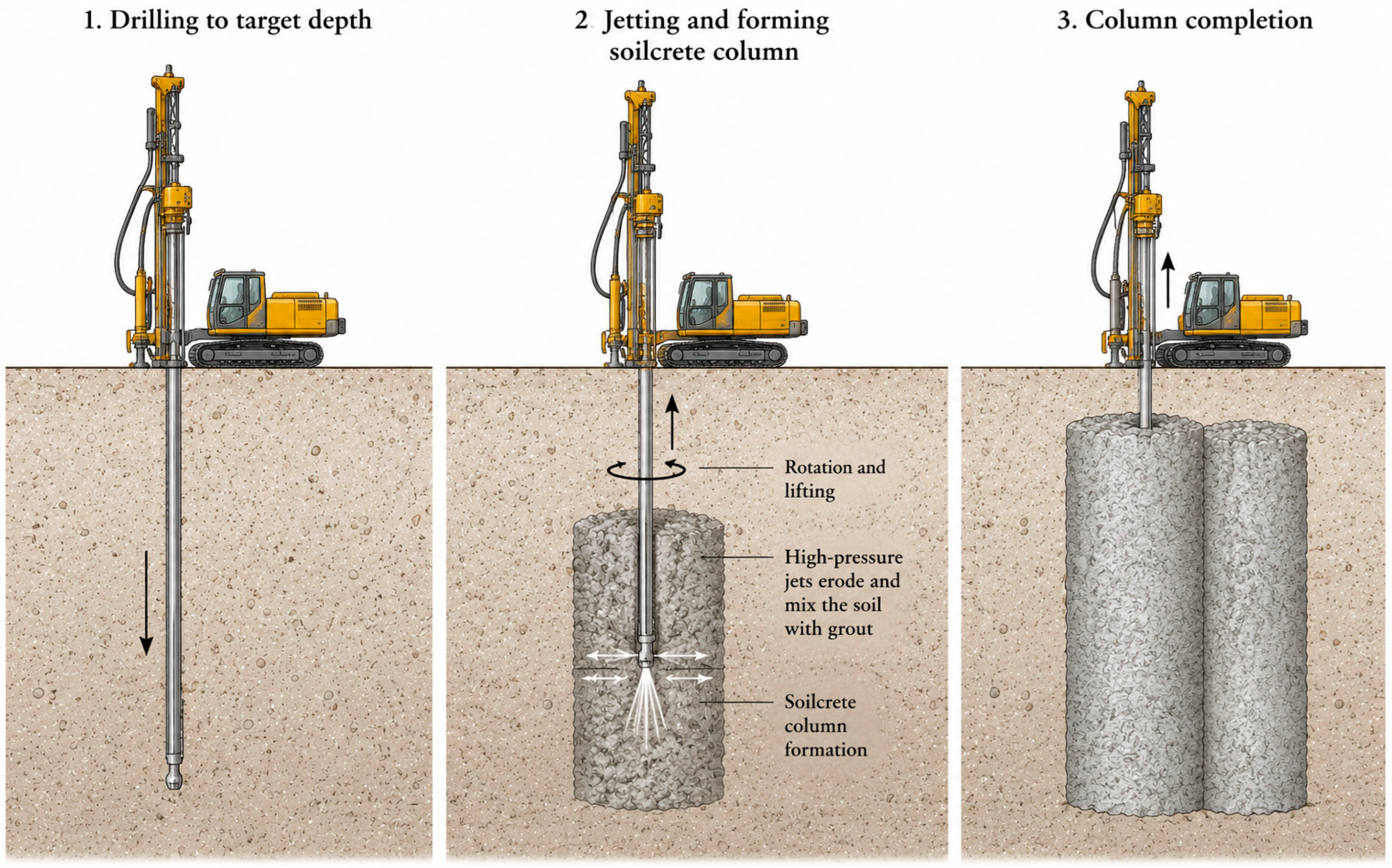
The basic principle of jet grouting is illustrated in
Figure 1. During installation, high-pressure jets erode and mix the in situ soil with cementitious grout, and the treated zone hardens into a soilcrete column or panel.
Field observations show that JG installation can induce lateral and vertical ground movements that decay with distance and may interact with retaining and adjacent structures or infrastructure. Instrumented trials and case-based studies report measurable ground and structural response during column installation, supporting the view that installation-stage effects can be significant—particularly in soft clays—and should be assessed alongside excavation-stage demands [
2,
3,
4,
5,
6]. Transient pore-water pressure changes may also be significant near the jetting zone, and piezometric trends can help guide construction decisions during execution [
3,
6].
Operational and environmental risk becomes more relevant under groundwater conditions, where pressure transmission and preferential pathways can lead to instability and uncontrolled spread of grout or fluids. Recent numerical work on grout-slurry flow in rough fractures further supports the importance of preferential flow geometry for grout migration and confinement control, although such mechanism-based studies still need to be linked with field monitoring evidence for TAP development [
7].
Quality-control case studies emphasise observational monitoring and process control for works below the groundwater table, including potential manifestations such as upward flow and boiling [
8]. Case studies further suggest that observations during execution—especially returns/spoil discharge behaviour and sudden changes in grout take—can provide early warning of loss of control [
9,
10,
11].
Environmental constraints are often dominant in contaminated ground, where exposure prevention and limiting contaminant spread can govern sequencing, containment measures, and spoils/returns handling [
12].
In addition to direct exposure pathways, grout–groundwater interaction can cause hydrogeochemical changes, such as elevated pH in groundwater, which may require monitoring and response planning where hydraulic connectivity exists [
13,
14]. The handling, reuse, and disposal of JG-derived waste streams can also influence the broader environmental footprint of the works [
15].
For cut-offs and bottom plugs, performance depends strongly on continuity, geometric uncertainty, and the risk of defects and leakage, so these works require careful verification and performance monitoring [
16,
17,
18].
Although the literature provides useful findings on ground response, process control, contaminated-ground practice, and barrier performance, these findings are still spread across different project types and topics [
6,
8,
12,
16,
18]. Existing reviews and technical summaries commonly address jet-grouting design, execution, quality control, or specific application fields, whereas fewer studies integrate environmental and operational risk pathways with monitoring indicators and predefined response actions.
This paper addresses that gap in three ways. First, it organises dispersed field- and practice-based findings within a Source–Pathway–Receptor (SPR) taxonomy tailored to jet grouting, building on the broader logic of source–pathway–receptor risk formation [
19]. Second, it standardises cross-case interpretation around monitoring relevant signals, with emphasis on how abnormal response is identified through trend, persistence, spatial extent, and agreement between instrument readings, process records, and field observations. Third, it uses these recurring patterns as the basis for a practical, monitoring-oriented Trigger–Action Plan (TAP) framework that can be calibrated to project-specific receptor tolerances and risk conditions, while remaining aligned with the wider trigger–response planning logic used in practice [
20,
21]. The contribution of this review should therefore be understood as a structured synthesis and operationalisation of dispersed field- and practice-based evidence, rather than as a new model derivation, field experiment, or numerical validation study. The paper does not propose universal numerical thresholds; instead, it provides a transferable decision-support structure for project-calibrated monitoring and response in jet-grouting practice.
Aim and Objectives
The aim of this review is to synthesise field- and practice-oriented findings on environmental and operational risks in jet grouting and to translate recurring monitoring-relevant patterns into a practical Trigger–Action Plan (TAP). The specific objectives are as follows:
To organise the main source–pathway–receptor relationships governing environmental and operational risk in jet grouting into a practical SPR taxonomy;
To compare selected case studies across recurring pathway classes, with emphasis on measurable early-warning signals from monitoring data, process records, and field observations; and
To formulate a monitoring-oriented Trigger–Action Plan (TAP) structure that links trigger levels with predefined response actions and can be calibrated to different jet-grouting contexts.
2. Review Methodology
2.1. Review Approach and Scope
This study uses a targeted case-based literature review focused on monitoring-relevant field and practice evidence in jet grouting (JG). It was designed to support the development of a Source–Pathway–Receptor (SPR) taxonomy and a monitoring-oriented Trigger–Action Plan (TAP) structure. The review was not intended as a full systematic review or meta-analysis of all jet-grouting studies. Instead, the search and selection process prioritised publications that provided sufficient information on construction context, ground and groundwater conditions, monitoring set-up, observed response, process behaviour, corrective actions, and relevance for trigger development.
The review process was organised into four steps: (i) database and supplementary searches, (ii) title and abstract screening, (iii) full-text eligibility assessment, and (iv) standardised information extraction and cross-case synthesis. The screening process is summarised using a PRISMA-style workflow, while the review is explicitly positioned as a targeted case-based synthesis rather than a formal PRISMA systematic review.
Accordingly, the review includes
Ground deformations and interaction with structures: instrumented field trials and practice-oriented case histories reporting installation-induced heave/settlement and lateral displacement during JG, including interaction with adjacent structures and excavation systems, and explicitly addressing abnormal or unexpected deformation responses relevant for defining monitoring triggers and response actions [
2,
4,
6,
22].
Pore-water pressure and hydrogeological response: field observations reporting pore-water pressure transients and their dissipation and spatial extent during JG, used to interpret hydrogeological response under groundwater conditions and to define monitoring-relevant trends (i.e., expected pressure rise and decay patterns rather than incident behaviour) [
6,
23,
24].
Hydraulic incident scenarios and accidental releases: construction-control and practice-oriented case histories describing situations in which injected grout or flushing fluid was not effectively confined to the intended treatment zone (e.g., loss of confinement, upward flow, sand boiling, or unintended migration), together with early-warning indicators, relevant operational parameters, and reported mitigation measures [
9,
10,
11,
24].
Jet grouting in contaminated ground (exposure pathways and site controls): contaminated-site and environmental-control case applications addressing environmental and occupational safety measures, containment, and the management of contaminated spoils, returns, and exposure pathways. Where reported, groundwater-quality and hydrogeochemical effects associated with cementitious grout interaction (e.g., changes in pH and ionic composition) are also considered as part of contaminated-ground controls and monitoring needs [
12,
13,
14,
15,
25].
Barrier performance in cut-offs and bottom plugs (defects, leakage, and verification): design-oriented contributions directly relevant to the environmental performance of JG barriers, with a focus on watertightness, the implications of defects and leakage, uncertainty in geometry and continuity, and verification approaches that can be translated into monitoring needs [
16,
17,
26,
27].
Spoil/returns management and secondary environmental effects under normal operations: practice-oriented studies addressing routine spoil and returns monitoring (e.g., return flow and volume balance), the maintenance of stable discharge and sufficient handling capacity to prevent overflows and spills, and downstream treatment, reuse, or disposal considerations where relevant to environmental performance and monitoring triggers [
8,
10,
11,
15].
Analytical or semi-analytical studies were included only where they were explicitly linked to field observations and supported monitoring-relevant interpretation, for example, by helping to define measurable indicators, threshold logic, or plausible failure and incident pathways that could be incorporated into a trigger–action framework.
2.2. Search Strategy and Study Selection
The literature set was assembled through a targeted search strategy and additional citation screening. The search strategy combined the core term “jet grouting” with monitoring-, risk-, groundwater-, environmental-, and performance-related terms aligned with the objectives of the review. Search was conducted in Scopus and Web of Science Core Collection and was complemented by Google Scholar to capture conference proceedings and practice-oriented case reports. The search logic used for each source is summarised in
Table 1.
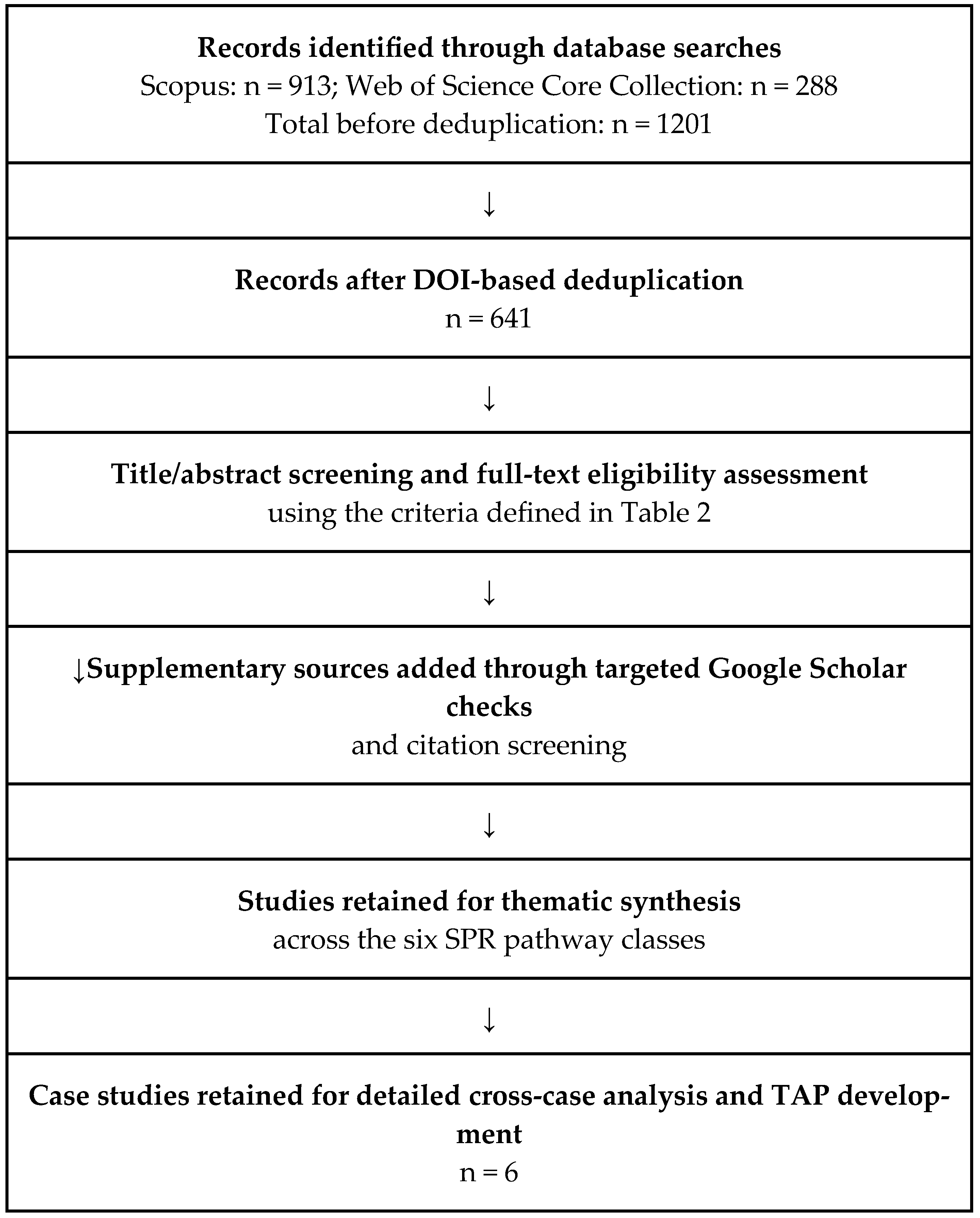
Database searches, last updated on 5 February 2026, retrieved 913 records from Scopus and 288 records from Web of Science, giving a total of 1201 records before deduplication. Records were then merged and deduplicated primarily by DOI matching, yielding 641 unique records. Additional practice-oriented sources were identified through targeted Google Scholar checks and citation screening and were retained where they provided field-based or implementation-relevant material not captured in the indexed database set.
Study selection was carried out in two steps. First, titles and abstracts were screened to identify publications likely to contain field-based evidence, monitoring-relevant findings, or useful practical detail. Second, the full texts of potentially relevant publications were assessed against the eligibility criteria defined in
Table 2, with emphasis on the reported construction context, ground and groundwater conditions, monitoring set-up, observed response, and relevance for trigger development.
Figure 2 summarises the screening and selection workflow used in the targeted case-based review.
Studies were excluded where jet grouting was only mentioned incidentally, where the work was purely laboratory, numerical, or theoretical without monitoring-relevant interpretation, or where the reporting detail was insufficient to support SPR classification or trigger–action interpretation. The most common reasons for exclusion were limited field context, lack of monitoring-relevant observations, a purely laboratory or analytical focus without practical interpretation, and insufficient reporting of outcomes relevant to monitoring or response actions. The review was therefore designed as a targeted case-based review for decision-support and TAP development rather than as a full systematic review or meta-analysis.
2.3. Selected Case Studies and Cross-Case Synthesis
Six case studies were selected for detailed analysis because they provided clear information on project context, execution conditions, monitoring observations, abnormal responses, and corrective actions needed for cross-case comparison and TAP development: Poh and Wong [
2], Ni and Cheng [
8], Wu et al. [
11], Corko et al. [
28], Debost et al. [
12], and Gazzarrini et al. [
27].
To standardise interpretation across heterogeneous case sources, information was extracted using the fields shown in
Table 3.
The selected case studies were then organised using the Source–Pathway–Receptor (SPR) structure. Each case was assigned to the pathway class that best represented its dominant monitoring or risk-control issue. Where a case was relevant to more than one pathway class, this secondary relevance was retained in the interpretation rather than forcing the case into a single exclusive category.
The cases were then compared across the standardised analytical fields listed in
Table 3 to identify repeated response patterns, practical early-warning indicators, and links between observed behaviour and response actions. Particular attention was given to situations in which escalation was identified more clearly from trends, persistence, spatial extent, or agreement between monitoring results, process records, and field observations than from a single exceedance value.
The purpose of this synthesis was therefore not only to summarise individual cases, but also to extract indicator–trigger–action relationships that support the generic TAP structure presented later in the paper.
2.4. Source Reporting and Applicability Assessment
Because the included sources are heterogeneous field trials, case histories, conference papers, and practice-oriented reports, a conventional risk-of-bias assessment was not directly applicable. Instead, the detailed case studies were assessed for reporting completeness and applicability to TAP development.
The assessment considered whether each source reported sufficient information on project context, ground and groundwater conditions, jet-grouting execution, monitoring set-up, process behaviour, abnormal response, corrective actions, and final outcome. Sources with limited detail were used only for thematic support, while the six most informative cases were retained for detailed cross-case comparison and TAP synthesis.
3. Risk Pathway Classification Based on the Source–Pathway–Receptor Concept
Jet grouting (JG) combines high-energy erosion, mixing, and cementitious grout injection and therefore interacts unavoidably with the surrounding ground–groundwater–structure system. The resulting impacts are often coupled (mechanical–hydraulic–operational) and depend on soil stratigraphy, groundwater regime, execution parameters, and installation sequencing. To organise field evidence in a way that directly supports monitoring design and an operational Trigger–Action Plan (TAP), this review uses the Source–Pathway–Receptor (SPR) concept to structure the main risk pathways.
Although SPR is widely recognised from contaminated-land practice, it is also used more broadly as a general conceptual model for risk formation in other hazard domains, where a risk requires a defined source (initiating driver), an enabling pathway (transmission mechanism), and an exposed receptor (asset or system that can be adversely affected) [
19]. In the context of jet grouting, “source” is interpreted broadly and includes not only chemical drivers (e.g., grout alkalinity, fines in returns) but also mechanical and hydraulic drivers, such as jetting energy and pressures, grout volume balance, transient pore-pressure loading, induced hydraulic gradients, and execution-induced disturbance. “Pathways” include stress redistribution in the ground, pore-pressure transmission, preferential flow routes (fractures, boreholes, service corridors), and unintended discharge routes for returns. “Receptors” include adjacent structures and retaining systems, excavations, groundwater bodies and connected infrastructure, workers (exposure), and the surrounding environment.
This SPR framing is intentionally practice-oriented: each pathway is described in terms of plausible scenario outcomes, measurable signals from instrumentation and process logs, and monitoring-relevant interpretation that can be operationalised into trigger thresholds and response actions.
To avoid overlap between pathway classes,
Table 4 defines the dominant issue and boundary of each SPR pathway used in this review.
3.1. Ground Deformations and Interaction with Structures
This section examines ground deformations induced by jet grouting and their interaction with adjacent structures and excavation support systems. The emphasis is on installation-related movements—heave, settlement, and lateral displacements—that may develop even before excavation stages and can become critical in urban environments with tight serviceability limits. Unlike the discrete incident scenarios addressed in
Section 3.3, the effects discussed here are typically part of the expected installation response; however, they still require systematic monitoring and predefined trigger levels because trends (rates and accelerations) may indicate abnormal escalation and increased risk to sensitive receptors.
Source (initiating drivers). Deformation-related impacts arise from the installation mechanics of jet grouting, where high-energy jetting and grout injection impose localised disturbance and temporary loading on the ground. Key initiating drivers include jetting pressure/energy, lift and rotation rates, grout take and the injected–returned volume balance, and sequencing decisions (adjacent spacing and time lag between neighbouring elements). These drivers control the intensity and duration of installation disturbance and influence whether the response is dominated by short-term heave, lateral displacement, or longer-term settlement.
Pathways (transmission mechanisms). Installation effects are transmitted to the surrounding ground through (i) stress redistribution and volumetric changes caused by erosion–mixing and grout replacement, and (ii) coupling with temporary increases in pore water pressure in saturated soils. A third pathway becomes important whenever jet grouting is carried out close to existing or temporary structures that are stiffer than the surrounding soil—for example, excavation support walls, foundation piles, tunnels, buried culverts, or similar underground structures. In such cases, the ground cannot deform freely; part of the installation-induced ground response is therefore expressed as movement and loading in these structural elements (soil–structure interaction). The observable outcomes typically include vertical ground movements (heave and/or settlement) and horizontal displacements, generally largest in the near field and decreasing with distance.
Heave can be the main installation response in soft clays. Its magnitude depends on execution parameters and generally decreases with distance from the treated zone [
4]. This makes heave a practical early-warning signal for construction control and supports defining monitoring zones (near-field vs. farther zones) and trigger levels that account for distance and receptor sensitivity in the TAP.
Receptors (affected assets). The main receptors for this pathway are nearby structures and infrastructure (buildings, utilities, tunnels), excavation support systems (e.g., diaphragm walls, sheet pile walls), and the excavation itself. In dense urban settings, allowable ground and structural movements are very small. If excavation or dewatering is already causing movement, any additional movement induced by jet grouting increases the total movement and may exceed the allowable limits. When a nearby structure or structural element is significantly stiffer than the surrounding soil, it limits how the ground can deform. Part of the jet grouting–induced ground response is then transferred to that element and becomes visible as structural movement and increased structural demand (e.g., deformation and higher internal forces). Deformation monitoring should therefore measure both free-field ground movements and the response of critical structural receptors, and these measurements should be evaluated together to understand the overall behaviour.
Monitoring implications and trigger logic. For deformation-dominated pathways, monitoring should combine (i) surface settlement/heave points (or automated levelling where needed), (ii) inclinometers in the ground and, where relevant, within stiff structural elements, and (iii) additional structural response measurements where critical receptors require them, such as deformation, tilt, and, where possible, measurements related to internal forces. Triggers should not be based only on absolute displacement values; rates and trend changes are equally important (e.g., accelerating heave, sustained lateral movement, or a widening difference between near-field and farther-field response). Process logs (pressure, flow rate, lift/withdrawal rate, and returns behaviour) provide essential context for interpreting observed movements and for distinguishing expected installation signatures from abnormal escalation.
3.2. Pore-Water Pressure and Hydrogeological Response
This section considers pore-water pressure response during jet grouting and its role in monitoring and construction control. The emphasis is on pressure changes that are normally expected during installation, particularly temporary increases that dissipate, and on how these trends can provide early warning when interpreted together with ground movements. Discrete hydraulic incident scenarios—where grout or flushing fluid escapes the intended treatment zone (e.g., into an excavation, a utility, or to the ground surface)—are discussed separately in
Section 3.3.
Source (initiating drivers). Pore-water pressure changes during jet grouting are caused by jetting and grout/fluid injection below the groundwater table. The magnitude and duration of these pressure increases are mainly controlled by jetting pressure and flow rate, lift/withdrawal rate, injected grout/fluid volumes, and the balance between injected and returned fluids [
3,
23]. In low-permeability soils, pore-pressure increases can be large and long-lasting, and may therefore require close monitoring rather than being treated as a short and routine part of installation [
3].
Pathways (transmission mechanisms). Once generated, excess pore pressures spread through the ground via two main mechanisms that are particularly relevant for construction control:
Pore-water pressure propagation and ground movements. A temporary increase in pore pressure reduces effective stress and can therefore precede or accompany ground movements such as heave and lateral displacement. This is particularly important in soft clays, where the response during installation is often close to undrained conditions [
3,
4]. For this reason, pore-pressure trends are useful early-warning signals when interpreted together with deformation measurements.
Preferential flow pathways for pore water and injected fluids. Pore-pressure response may also indicate transmission along preferential routes, such as boreholes, fractures, coarse layers, service corridors, or interfaces between treated and untreated ground. In works below the groundwater table or under difficult hydraulic conditions, such connectivity can progress from a pressure response into operational anomalies and instability phenomena, which may require immediate adjustments and/or contingency measures [
7].
In deep excavations, pore-pressure effects may interact with retaining systems and dewatering regimes. Jet-grouted slabs or blocks can modify the hydro-mechanical boundary conditions of a braced excavation; pore-pressure changes should therefore be considered alongside excavation-induced demands and staged construction effects when defining monitoring triggers [
6].
Receptors (affected assets). The main receptors for this pathway are nearby structures and utilities that can be affected by settlement/heave and lateral movements. Additional receptors include the excavation and its support system, and the groundwater system itself. In environmentally sensitive settings—such as areas with protected groundwater resources or strict water-quality requirements—groundwater is an important receptor because pore-pressure changes can change flow direction and increase hydraulic gradients. This can increase seepage and promote the movement of suspended fines or grout-related constituents.
Monitoring implications and trigger logic. For the pore-pressure pathway, monitoring should be designed to capture both magnitude and time evolution of response. A minimum setup typically includes vibrating-wire piezometers (or equivalent) at representative distances and depths, complemented by standpipe piezometers where appropriate for groundwater level reference. Where risk is higher (tight deformation tolerances, active dewatering, layered permeability contrasts, or previous history of hydraulic anomalies), automated acquisition with short sampling intervals is preferred so that rate-based triggers can be applied during active jetting [
3,
8].
Trigger levels should not be based only on absolute pore-water pressure values. A pore-pressure rise is often a normal installation response, so the key is to identify patterns that suggest the response is larger, longer, or more widespread than expected:
Rate and duration: pore-water pressure can rise quickly during jetting, but it becomes a warning sign if the rise is unusually rapid, reaches unusually high values, or remains elevated and dissipates slowly after jetting stops.
Extent: it is more concerning if the pore-pressure response appears at larger distances from the treated zone, or at depths where no significant response is expected.
Consistency with process data: pore-water pressure changes should be interpreted together with the execution records (e.g., jetting pressure/flow, lift rate, injected and returned volumes). A warning sign is a pressure response that is disproportionate to parameter changes, persists after jetting stops, occurs at unexpected locations, or appears without a corresponding operational change.
Link to movements: pore-pressure increases are more critical when they occur together with accelerating heave or lateral movements, indicating a coupled hydro-mechanical response [
3,
4].
These signals provide a practical basis for tiered triggers (e.g., alert/action/stop) and for pre-defined response actions in the TAP, ranging from intensified monitoring and parameter adjustment to temporary cessation where abnormal hydraulic behaviour is suspected [
8].
3.3. Hydraulic Incident Scenarios and Accidental Releases
This section addresses hydraulic incident scenarios during jet grouting in which injected fluids escape the intended treatment zone. Unlike the pore-water pressure response described in
Section 3.2, these cases involve loss of confinement rather than the expected short-term pressure increase followed by dissipation. Grout or flushing fluid may then migrate into adjacent ground, excavations, utilities, or to the ground surface, and immediate mitigation measures may be required. Routine spoil/returns management and related secondary environmental effects under normal operations are discussed separately in
Section 3.6.
Source (initiating drivers). Hydraulic incidents may occur when jetting and injection create pressures or hydraulic gradients that cause loss of confinement or open an unintended flow path. Common initiating drivers include high jetting pressure and flow rate, poorly controlled or overly rapid lift/withdrawal, a clear imbalance between injected and returned fluids (for example, sudden loss of returns), work below the groundwater table, and ground conditions that favour instability, such as permeable layers, loose granular soils, or strong permeability contrasts [
8,
9].
The risk may be higher where existing permeable features or hydraulic connections allow injected grout or flushing fluid to escape during jetting. Examples include fractures, gravel lenses, old boreholes, utility trenches, or direct connections to excavations and drainage systems. In such cases, injected fluids may migrate unexpectedly or break through into locations outside the intended treatment zone [
18].
Pathways (transmission mechanisms). Incident pathways differ from the pore-pressure transients discussed in
Section 3.2 because they involve unintended or uncontrolled flow routes and/or instability phenomena. Three recurring pathway classes are particularly relevant.
Unintended fluid migration outside the treatment zone. Injected grout or flushing fluid may travel along preferential routes—such as fractures, coarse lenses, soil interfaces, old boreholes, or service corridors—and reach locations outside the intended treatment zone. This may be observed as grout/fluid entering a nearby excavation, a utility or drainage line, a basement, or appearing at the ground surface. The key issue is not the pore-pressure increase itself, but the activation of a hydraulic connection that provides a direct path for injected fluids to escape the treatment zone [
18].
Upward flow along the borehole and soil instability. If hydraulic gradients become unfavourable and confinement is insufficient, injected fluid and pore water may move upward along the borehole. In granular soils, this may lead to visible instability, such as upward seepage carrying soil particles. Such conditions require immediate construction-control actions to stop the upward flow and restore stability, typically by adjusting or temporarily pausing the execution and implementing site-specific stabilisation measures [
8].
Returns anomalies as an early warning of incident development. Abnormal returns behaviour is considered here as an early warning sign of a developing hydraulic incident, rather than as routine spoil/returns management (
Section 3.6). Examples include sudden loss or strong reduction of returns, highly irregular discharge, or returns appearing at unexpected locations. Such patterns may indicate that injected fluid is being diverted into an unintended pathway or that pressure is building up in the ground. Case histories near tunnels show that poor control of returns discharge and execution parameters can lead to unintended fluid migration and larger ground response, whereas stable discharge and controlled operation help keep the response within expected limits [
11].
Receptors (affected assets). Key receptors include the excavation and its support system. Nearby structures and underground infrastructure (utilities, tunnels, basements) are also important receptors, especially where fluid ingress or ground disturbance is possible. Worker safety and the immediate site environment become direct receptors in cases of surface release or uncontrolled discharge [
8].
Monitoring implications and trigger logic. Because escalation can occur rapidly, early warning often appears in operational signatures and field observations, not only in instrumentation trends. The following indicators are commonly actionable as incident triggers:
Sudden loss or major reduction of returns under otherwise stable operating settings, or an abrupt increase in apparent grout take, is inconsistent with expected ground conditions [
8,
9].
Unexpected pressure/flow behaviour (spikes, unstable oscillations, or unusual sensitivity to small parameter adjustments) suggesting loss of confinement, blockage, or redirected flow [
9].
Direct evidence of unintended release, such as grout/fluid appearing in utilities, basements, excavations, or at the ground surface, or seepage/wet spots developing at unexpected locations [
8,
18].
A combined anomaly pattern, where operational anomalies occur together with rapidly accelerating deformations or unexpected response at sensitive receptors (e.g., tunnels), indicating that conditions have moved beyond the expected transient regime [
11].
In a TAP, these indicators are best treated as scenario-based triggers, that is, as patterns of abnormal behaviour rather than isolated exceedances. They usually require a stronger response than pore-pressure transients alone (
Section 3.2). Response actions may progress from immediate checks and intensified observation to rapid parameter reduction and measures to restore hydraulic control and ground stability. Where unintended fluid migration, upward flow, or surface release is suspected, work may need to be temporarily stopped until the situation is brought under control and revised measures are in place [
8,
9].
3.4. Jet Grouting in Contaminated Ground: Exposure Pathways and Site Controls
This section addresses jet grouting executed in contaminated soil and/or groundwater, where the primary concern is preventing exposure and preventing the spread of contaminants. The focus is on practical exposure pathways and site controls during execution, while routine spoil/returns handling under normal (non-contaminated) conditions is discussed separately in
Section 3.6.
Source (initiating drivers). The main driver is contamination already present in the ground (soil, groundwater, or both). Jet grouting can create risk because it disturbs and mobilises contaminated material. During execution, contaminated material may be brought to the surface with returns and wet spoil, and may also be dispersed as fine spray or mist during jetting and returns handling. Cementitious grout may also change groundwater chemistry, most notably by increasing pH [
13,
14,
25]. Published case studies suggest that the need to protect workers and prevent contamination from spreading beyond the work area often influences the selected method, work sequence, and monitoring approach [
12].
Pathways (transmission mechanisms). In contaminated ground, the key pathways are those by which contaminants can reach people or spread beyond the work area:
Surface handling of contaminated returns/spoil. Returns and wet spoil can contain contaminants and become the main transport medium on site [
12].
Aerosols and splashing during execution. Mist, droplets, and splashes can create inhalation or contact pathways if not controlled [
12].
Migration through water. Changes in pore pressure, flow direction, and hydraulic gradients can increase seepage and promote movement of suspended fines or grout-related constituents, especially where groundwater is hydraulically connected [
13,
14].
Cross-contamination via equipment and logistics. Hoses, rigs, water circuits, and vehicle movements can transfer contaminated material outside the controlled zone if decontamination is insufficient [
12].
Off-site handling and disposal/reuse. Managing spoil/returns can shift impacts from the work zone to loading, transport, treatment, and final disposal or reuse. Environmental performance, therefore, depends on compliant handling, clear documentation/traceability, and verification testing when required [
15].
Receptors (affected elements). The main receptors are workers (inhalation and dermal exposure), the immediate site environment (surface spills and runoff), and connected groundwater and surface-water bodies affected by contaminant transport or grout-induced changes. In urban settings, nearby utilities and enclosed spaces (basements, service corridors) also act as receptors if fluids or vapours migrate into them [
12,
13].
Monitoring implications and trigger logic. Monitoring should be designed around exposure control and early detection of spread:
Triggers should be simple and easy to recognise on site. Examples include unexpected or persistent visible mist or splashing, spills outside the controlled zone, abnormal returns together with uncontrolled wet areas, or water-quality changes that exceed site criteria, such as a sharp rise in pH or water that suddenly becomes visibly cloudy where clear water is expected [
12,
13]. In a TAP, the response would usually move from tighter controls and increased monitoring to pausing works and applying containment and decontamination measures when loss of control is suspected [
12].
3.5. Barrier Performance in Cut-Offs and Bottom Plugs: Defects, Leakage, and Verification
This section examines jet grouting used as a hydraulic barrier in cut-off walls and excavation bottom plugs. In these applications, the key risk is not the expected installation response (
Section 3.1 and
Section 3.2) but insufficient watertightness due to geometrical variability, imperfect continuity, or defects. The discussion focuses on how leakage can develop, what it affects, and how monitoring and verification can be linked to practical trigger–action logic in a TAP.
Source (initiating drivers). The primary initiating driver is uncertainty in barrier continuity and geometry. In practice, jet-grouted elements may vary in diameter, position, and overlap, and local defects may occur even when execution parameters are within specification. This uncertainty is central to barrier performance and is often treated explicitly in design, including probabilistic approaches for bottom plugs and watertightness [
16,
17,
26]. Sensitivity increases when the barrier is required to resist a significant hydraulic head difference or when construction constraints limit access, sequencing, or verification.
Pathways (transmission mechanisms). Leakage and loss of hydraulic function typically occur through a small number of clear pathway types:
Untreated gaps between adjacent columns/panels. Narrow, untreated zones between columns/panels can act as preferential seepage paths.
Local defects within elements. “Windows”, weak zones, or discontinuities within soilcrete can locally increase permeability.
Interfaces and edge bypass routes. Seepage can occur at the edges of the jet-grouted barrier if it is not fully connected to the surrounding low-permeability ground or to adjacent structures. This can happen when column/panel overlap is incomplete near the boundary, when element diameters or positions vary locally, or when the barrier is not properly keyed into the underlying low-permeability layer or tied into nearby structural elements. In these cases, water can bypass the main soilcrete body by flowing along the edge zone or around the barrier [
16,
26].
System response as the water-level difference increases. In cut-offs and bottom plugs, a water-level difference across the barrier is often present and typically increases during staged dewatering. As this driving force increases, seepage tends to concentrate through the weakest available path—often a single local gap, defect, or incomplete tie-in. Barrier performance should therefore be assessed at the system level (e.g., excavation inflow and piezometric levels across the barrier), because local quality checks alone may not identify the controlling leakage path [
17].
Receptors (affected elements). The main receptors are the excavation and its support system. Poor barrier performance can lead to higher inflow, loss of control of groundwater conditions, and—in bottom-plug applications—an increased uplift risk at the excavation base. Nearby ground and structures are also receptors because drawdown and redirected seepage can cause additional settlements or other ground movements. In water-retaining or environmentally sensitive applications, the key receptor is the water body or groundwater area behind the barrier (e.g., a reservoir or a protected aquifer), because the barrier must keep seepage low and maintain the required water levels and flow conditions on the protected side [
27].
Monitoring implications and trigger logic. For barrier applications, monitoring should combine (i) hydraulic performance monitoring and (ii) verification of continuity:
Hydraulic performance monitoring: piezometric levels inside/outside the barrier, excavation inflow rates, pump operation records, and observations of seepage occurrence and location.
Continuity/performance verification (QA/QC): targeted coring and logging, permeability or water tests where applicable, and verification against design assumptions on overlap and geometry [
16,
26].
Trigger logic should be simple and based on performance signals, for example.
Inflow rates are higher than expected for the current excavation stage.
Appearance of seepage at unexpected locations (new wet spots, localised inflow points).
Piezometric response inconsistent with the intended cut-off function (e.g., limited head separation across the barrier).
Trends that worsen with time or with increasing head difference [
17].
In a TAP, typical responses progress from rapid verification (confirm instrumentation and review construction records) to focused investigation of suspected leakage zones and, if needed, local remedial works to restore barrier continuity and performance under revised controls [
16,
26,
27].
3.6. Spoil/Returns Management and Secondary Environmental Effects Under Normal Operations
This section addresses routine environmental effects of jet grouting that arise from producing, handling, and disposing of returns (the grout–water–soil mixture that comes back to the surface) and spoil (the separated solid fraction). The focus is on impacts that are normally manageable with good site practice, but can escalate if handling capacity and housekeeping are inadequate.
Source (initiating drivers). Spoil and returns are generated because jet grouting erodes and mixes the ground while grout and flushing fluid are injected. The volume and consistency of returns depend on execution parameters (pressure, flow, lift/withdrawal rate), the jet grouting system, and soil conditions. Operational choices, therefore, control how much material must be collected, separated, stored, and transported [
9,
10].
Pathways (transmission mechanisms). Under normal operations, the main pathways are simple and related to site handling:
Surface spills during collection and transfer. Returns can spill or overflow at the borehole collar, from hoses, or from tanks and separation units. Wet spoil can then be spread around the site by vehicles and equipment if traffic routes and cleaning are not properly controlled.
Insufficient or unstable discharge capacity. If the discharge/transport system cannot remove returns continuously, material can back up at the work area and increase the likelihood of spills and uncontrolled wet areas. Improving discharge capacity and stability reduces these problems [
10].
Separation and water management. Settling and separation produce a water phase that may be visibly cloudy and alkaline. If this water is not managed (storage, recirculation, or compliant disposal), it can affect local drainage and receiving systems.
Off-site transport, treatment, and reuse/disposal. Impacts can shift from the work zone to hauling and final management. Environmental performance depends on controlled loading, documentation, and compliant treatment or reuse routes. Some studies evaluate reuse options for jet-grouting waste in construction materials, highlighting the importance of engineered handling and verification [
15].
Discharge configuration in constrained settings. Case evidence shows that the discharge strategy can influence whether impacts remain local or spread toward sensitive underground assets [
11].
Receptors (affected elements). The main receptors are the
work area and immediate surroundings (slips, nuisance wet areas, surface staining),
site drainage and nearby properties (runoff and deposition of fine material), and
off-site receptors linked to transport and disposal/reuse. In urban settings,
utilities and drainage lines are important receptors because they may be affected by unintended inflow of returns or fine-rich water [
11].
Monitoring implications and trigger logic. Monitoring is mainly observational and operational, supported by simple checks:
Execution records: injected vs. returned volumes and discharge continuity (to detect unusual imbalance and handling limitations) [
10].
Field observations: check for (i) spills or overflows, (ii) wet areas spreading outside the work zone, (iii) returns flow that is not steady (it stops and restarts, or comes in surges), and (iv) returns appearing where they should not (e.g., in drains, manholes, or outside the collection area).
Water management checks (where applicable): pH and visual clarity of separated water, and confirmation that storage capacity and disposal routes are adequate [
15].
Practical triggers should be straightforward, for example
Repeated spills/overflow during otherwise stable operations;
Sustained inability to maintain continuous returns discharge;
Uncontrolled wet areas or runoff leaving the work zone;
Separated water that becomes unexpectedly alkaline or visibly cloudy compared with site criteria.
In a TAP, responses typically progress from housekeeping and discharge adjustments (capacity, routing, stabilising the discharge process) to short pauses if control cannot be restored, before resuming under revised handling measures [
9,
10,
11].
4. Case-Based Review: Case Comparison and Synthesis for Monitoring TAP Development
Section 3.1,
Section 3.2,
Section 3.3,
Section 3.4,
Section 3.5 and
Section 3.6 define the main pathway classes used in this review. This section compares the selected field- and practice-based cases on a common basis and uses them to identify practical monitoring triggers and response actions for the Trigger–Action Plan (TAP). The emphasis is on the information most relevant for monitoring and control, including observed response, early warning signs, actions taken, and their outcomes.
4.1. How the Cases Are Organised
Each case is interpreted through the dominant Source–Pathway–Receptor (SPR) pathway that best explains the main issue reported and its main monitoring implication. Together, the selected cases cover the main pathway types introduced in
Section 3.1,
Section 3.2,
Section 3.3,
Section 3.4,
Section 3.5 and
Section 3.6 and provide the basis for the monitoring protocol and Trigger–Action Plan (TAP) developed later in the paper.
For comparability, all cases are reviewed using the same core information, including project context, ground and groundwater conditions, jet-grouting system and execution characteristics, monitoring set-up, observed response or anomalies, mitigation measures, and TAP-relevant lessons. The level of detail varies between cases depending on the information reported in each source. To make the cross-case comparison more explicit,
Table 5 summarises the six selected cases using the same analytical fields. The table also highlights the main monitoring or control signals used in each case, including deformation measurements, piezometers, tunnel response instruments, spoil/returns records, air-quality or containment controls, and water-quality indicators where reported.
4.2. How the Synthesis Produces TAP Logic
The selected cases are subsequently compared across pathway types to identify recurring early-warning signals, patterns of abnormal escalation, and response measures that can be translated into practical monitoring logic. Particular attention is given to signals that can be used during execution, including instrumentation trends, process records, and simple site observations.
The synthesis focuses on four main aspects: which signals are consistently observed in practice, how escalation is more reliably identified from trends and persistence than from a single exceedance, how combined signals can strengthen interpretation, and how these patterns can be translated into action-oriented trigger levels. The outcome is a set of recurring indicator–trigger–action relationships that support the generic monitoring-oriented TAP presented later in the paper.
4.3. Case Study 1: Instrumented Field Trial in Soft Marine Clay—Ground Deformation, Pore-Pressure Response, and Diaphragm-Wall Interaction
This case provides field evidence for the responses discussed in
Section 3.1 (ground deformation and interaction with structures) and
Section 3.2 (pore-water pressure and hydrogeological response).
Table 6 summarises the key information extracted for Case Study 1.
Evidence source: Poh & Wong (2001) [
2],
A field trial of jet-grouting in marine clay.
TAP-relevant early-warning signals and response logic
The measured distance-decay supports a zone-based trigger concept with tighter sensitivity in the near field and at structural boundaries (
Section 3.1). Pore-pressure increases can be transient during jetting, so escalation should be judged by trend, persistence, and spatial spread rather than a single absolute value (
Section 3.2). Where diaphragm walls are present, wall movement/structural response should be included explicitly in the trigger set and interpreted together with excavation-stage effects.
4.4. Case Study 2: Quality Control of Double-Fluid Jet Grouting Below the Groundwater Table
This case provides field evidence for the responses discussed in
Section 3.2 (pore-water pressure and hydrogeological response) and
Section 3.3 (hydraulic incident scenarios and accidental releases), while also illustrating the value of process control and observational QA/QC in jet grouting below the groundwater table.
Table 7 summarises the key information extracted for Case Study 2.
Evidence source: Ni & Cheng (2014) [
8], Quality control of double-fluid jet grouting below groundwater table: Case history.
TAP-relevant early-warning signals and response logic
Action: treat as loss-of-control potential: tighten supervision of returns and groundwater controls, check for developing seepage paths (especially near retaining elements), and be prepared to pause jetting locally if escalation persists.
Action: stop and stabilise the situation (manage heads, restore containment/flow paths, remove blockages), then resume only once conditions are controlled.
4.5. Case Study 3: Horizontal Spoil-Discharge Jet Grouting near Existing Tunnels—Instrumented Tunnel Response and Pore-Pressure Monitoring
This case provides field evidence for the responses discussed in
Section 3.1 (ground deformation and interaction with structures) and
Section 3.2 (pore-water pressure and hydrogeological response), with a strong focus on receptor monitoring (existing tunnels) during jet grouting works carried out in close proximity. It also illustrates how spoil-discharge control and process stability support trigger-based decision-making during sensitive proximity works.
Table 8 summarises the key information extracted for Case Study 3.
Evidence source: Wu et al. (2020) [
11],
Ground Response to Horizontal Spoil Discharge Jet Grouting with Impacts on the Existing Tunnels. TAP-relevant early-warning signals and response logic
Trigger (receptor response/tunnel): rising or accelerating tunnel response indicators (e.g., hoop strain, vertical displacement, rotation), even if ground indicators remain moderate.
Action: treat tunnel response as potentially governing in the influence zone; immediately review operational parameters and sequencing, reduce jetting energy (pressure/flow) and/or slow the advance rate, and apply a local hold-point until the trend stabilises.
Trigger (hydrogeological/pore pressure): pore-pressure increase that shows unfavourable trend characteristics (rapid rise, persistence after jetting stops, or spatial spread to sensors outside the expected influence zone).
Action: escalate based on trend/persistence/spread rather than a single absolute value; adjust execution to reduce pressure build-up (parameter reduction, pauses, revised sequencing), and expand monitoring frequency/coverage until dissipation behaviour returns to expected.
Trigger (process/returns and spoil discharge stability): abnormal or unstable spoil discharge/returns behaviour (e.g., sudden reduction/loss of returns, irregular discharge, repeated anomalies), interpreted as loss of disturbance-control effectiveness.
Action: treat as an early warning of potential loss-of-control; immediately adjust parameters to regain stable discharge (reduce energy, review discharge path/handling, confirm no blockages), and introduce a hold-point before continuing within the tunnel-influence zone.
Action: prioritise robust discharge management (capacity, continuity, operational checks) as part of the baseline control plan; define explicit acceptance criteria for discharge stability and link them to pre-planned response steps.
4.6. Case Study 4: Jet Grouting for In Situ Stabilisation of a Municipal Solid-Waste Landfill—Pilot Trial in Highly Heterogeneous Waste
This case complements
Section 3.4 by showing how contaminated or waste-like ground can introduce additional material-performance and constructability uncertainties, particularly in relation to binder response, treated-mass continuity, and pilot-based verification under highly heterogeneous conditions.
Table 9 summarises the key information extracted for Case Study 4.
Evidence source: Corko et al. (1997) [
28],
Experiences with jet-grouting technology applied to the remediation of old dump sites. TAP-relevant early-warning signals and response logic
Action: treat as a nonconformance for the selected mix; stop using the ineffective binder, switch to a binder system that develops strength in situ (e.g., cement or lime–cement), and re-validate the recipe with site-specific trial mixes/lab checks before proceeding to larger-scale treatment.
Trigger (constructability/heterogeneity effects): repeated encounters with large solid bodies (e.g., metal items, concrete blocks) causing local disruption of column formation and/or unacceptable variability.
Action: treat as a predictability/quality risk; implement pre-probing or targeted removal where feasible, adjust the treatment layout (overlap, spacing, local re-treatment), and introduce additional verification points in zones where obstructions are expected.
Trigger (interaction with polluted pore fluids): indications that polluted water is interacting strongly with the grout (e.g., visible colour change in the grout mass), with potential implications for washout or reduced effectiveness.
Preventive control noted in the case: staged pilot testing with multiple mixes and parameter variations, followed by excavation-based verification after curing, to confirm constructability and treated-mass characteristics before scaling up.
4.7. Case Study 5: Jet Grouting Within a Contaminated Former Gas-Works Site—EHS Controls and Binder Selection in Coal-Tar Environments
This case links
Section 3.4 (contaminated ground—EHS and containment during jet grouting) with
Section 3.5 (barrier performance and verification). It shows how environmental containment, spoil/reflow control, and strength-based acceptance must be integrated when a jet-grouted containment wall is constructed in a chemically aggressive contaminated-ground setting.
Table 10 summarises the key information extracted for Case Study 5.
Evidence source: Debost et al. (2017) [
12],
Jet Grouting within Contaminated Land Fill. TAP-relevant early-warning signals and response logic
4.8. Case Study 6: Jet-Grouted Backup Seepage Cut-Off Wall in an Operating Earthfill Dam—Managing Hydrofracture Risk Under High Jet Pressures
This case is relevant to both
Section 3.5 (barrier systems and cut-offs) and
Section 3.2 (pore-pressure response and hydraulic connectivity). Its main value lies in showing how hydrofracture and hydro-jacking risk can govern construction control, requiring a field trial and a calibrated execution procedure before production works.
Table 11 summarises the key information extracted for Case Study 6.
Evidence source: Gazzarrini et al. (2017) [
27],
Construction of a Jet-Grouted Backup Seepage Cut-Off Wall in the John Hart North Earthfill Dam. TAP-relevant early-warning signals and response logic
Trigger (embankment response/stability): surface cracking, heave, wet spots, or other adverse surface expression developing along/near the alignment during jetting.
Trigger (process/returns and grout take): sudden change in returns behaviour (loss of returns, uncontrolled reflow) and/or sharp increase in grout take, consistent with new connectivity/fracture pathways.
Action: treat as a primary hydrofracture indicator; stop or reduce pressure; investigate the flow path; adjust the method (casing, pre-drilling, sequence), and only proceed when stable returns are re-established.
4.9. Cross-Case Comparison and Synthesis
As summarised in
Table 12, the six case studies collectively show that monitoring triggers for jet grouting should be defined using a receptor-first logic, that is, with protection of the most sensitive asset as the starting point, and interpreted together with process stability (returns/spoil behaviour and operational parameters). Across the cases, escalation is rarely governed by a single absolute threshold; instead, it is typically governed by trends, persistence, spatial spread, and corroboration across independent indicators.
Three synthesis points are most relevant for translating case evidence into a practical protocol:
Receptor-first triggering: where sensitive assets exist (tunnels, dams, excavation support), direct receptor response should be part of the governing trigger set.
Trend-based interpretation for pore pressure and groundwater indicators: escalation should consider direction, persistence, and spatial spread, and be interpreted together with execution stability.
Process stability as a leading indicator: abnormal returns/reflow, loss of returns, or sudden grout-take changes repeatedly coincide with adverse pathways (connectivity, hydrofracture, releases) and should be treated as early warnings.
6. Discussion
Previous research has provided valuable insights into individual aspects of jet grouting risk, including ground and structural response, pore-water pressure changes, hydraulic instability, contaminated-ground controls, and barrier verification [
3,
4,
6,
8,
12,
16]. However, these findings are usually reported within specific project contexts or technical themes rather than translated into a unified framework for monitoring and construction control. The main contribution of the present review is therefore not the identification of new mechanisms, but the integration of dispersed case-based findings into a common Source–Pathway–Receptor (SPR) structure and their translation into a monitoring-oriented Trigger–Action Plan (TAP).
This point is particularly important for pore-pressure and hydraulic response. Earlier studies have already shown that pore-pressure rise during jetting may represent a normal installation effect under groundwater conditions [
3,
6,
23]. The present synthesis extends that understanding by showing that monitoring significance increases when the response persists after jetting, appears outside the expected influence zone, or coincides with accelerating deformation or unstable return behaviour. This supports a more observational and pattern-based interpretation of monitoring results rather than a purely threshold-based one.
The review also highlights the importance of process behaviour within the trigger system. Across the analysed cases, return stability, spoil discharge, and grout-take anomalies repeatedly emerge as early indicators of changing ground response or hydraulic connectivity [
8,
9,
10,
11]. This suggests that they should be treated as primary monitoring signals rather than as secondary execution records, particularly because they may indicate loss of control earlier than instrumentation alone.
Another important implication is that trigger logic should follow a receptor-first approach. Cases involving tunnels, excavation support systems, cut-offs, and dams show that some receptors are much less tolerant of disturbance than others [
6,
11,
16,
27]. The present review shows that direct receptor response may govern escalation even when ground-level or process indicators remain moderate. For this reason, the proposed TAP is structured so that trigger levels can be calibrated primarily to receptor sensitivity and then interpreted together with the relevant source and pathway indicators.
The proposed TAP also has socio-economic relevance. In sensitive urban, infrastructure, dam, or contaminated-ground settings, uncontrolled jet-grouting responses can lead to construction delays, remedial works, damage claims, environmental non-compliance, and increased waste-handling costs. A monitoring-based TAP can reduce these risks by supporting earlier intervention, clearer responsibility for decisions, and more predictable construction control. In this sense, the proposed structure contributes not only to environmental protection but also to more reliable project delivery and reduced indirect costs.
At the same time, the review has clear limitations. The available literature remains heterogeneous in instrumentation layouts, baseline definitions, temporal resolution, site conditions, and the reporting of corrective actions. The proposed TAP should therefore be understood as a transferable decision-support structure rather than a universal set of numerical trigger values or a validated predictive model. Its main strength lies in structuring interpretation and response logic across different jet grouting applications, but calibration must remain project-specific and should account for receptor tolerance, soil stratigraphy, groundwater conditions, burial depth, execution parameters, and environmental criteria. Future work would benefit from more standardised case-reporting formats that jointly document execution parameters, monitoring response, return behaviour, corrective actions, and final performance outcomes.
7. Conclusions
This paper presents a targeted, case-based review of environmental and operational risks in jet grouting and formulates a monitoring-oriented Trigger–Action Plan structure based on Source–Pathway–Receptor logic. Rather than proposing a new predictive model or universal numerical thresholds, the study provides a transferable decision-support structure for linking key risk mechanisms, measurable warning signals, and predefined response actions across different jet grouting applications.
The review shows that escalation in jet grouting is most reliably identified through pattern-based interpretation of monitoring results, particularly by considering trends, persistence, spatial extent, and corroboration between instrumentation, process behaviour, and field observations. In sensitive settings, direct receptor response may govern escalation and should therefore be explicitly integrated into trigger logic.
The main findings can be summarised as follows: (i) deformation and pore-pressure responses should be interpreted together, especially in soft ground and groundwater conditions; (ii) returns/spoil behaviour and grout-take anomalies are important early-warning indicators of loss of control; (iii) direct receptor response may govern escalation in sensitive settings such as tunnels, dams, excavation support systems, and contaminated sites; and (iv) trigger values should be calibrated to receptor tolerance, ground conditions, groundwater regime, construction stage, and environmental criteria.
The proposed TAP is intended as a generic, project-calibrated framework for improving the consistency, transparency, and actionability of risk-informed monitoring and construction control in jet grouting.