1. Introduction
Egypt’s irrigation system comprises an extensive network of open canals, many of which are excavated in erosion-prone soils. The vulnerability of these soils to scour and bank instability necessitates careful hydraulic and geometric design to maintain flow velocities within permissible limits and ensure stable canal performance. Proper control of both the canal inside slope and the longitudinal bed slope plays a key role in regulating flow behavior, minimizing erosion risk and enabling more efficient flow conveyance, thereby supporting the long-term sustainability of water structures.
The entrance zone of water structures consists of two interacting components: upstream wing walls and the canal inside slope. Wing walls function as essential structural elements that retain backfill material and guide the approaching flow, promoting a gradual and stable hydraulic transition into the structure. In parallel, the canal inside slope is primarily governed by soil characteristics and stability constraints, while also influencing flow resistance and energy distribution.
A critical review of previous studies reveals that the hydraulic impact of wing wall geometry has been extensively investigated, whereas canal inside slopes have predominantly been addressed from a geotechnical perspective. More importantly, these two parameters have generally been examined in isolation, with limited consideration of their coupled hydraulic interaction under realistic flow conditions.
In practice, however, wing wall configuration and canal inside slope act simultaneously as an integrated system controlling flow contraction, turbulence intensity, vortex formation, and energy dissipation. This interaction directly governs sediment transport processes, bed shear stress distribution, and the magnitude and evolution of downstream scour. Neglecting this coupled behavior may lead to inaccurate prediction of scour characteristics and, consequently, suboptimal hydraulic design.
From a sustainability perspective, excessive downstream scour represents a critical challenge, as it accelerates structural degradation, increases maintenance frequency, and raises lifecycle costs of water structures. In addition, repeated sediment mobilization disrupts channel equilibrium, reduces conveyance efficiency, and contributes to long-term environmental degradation. Therefore, improving the integrated hydraulic performance of entrance zone components is essential for enhancing structural resilience, optimizing resource utilization, and extending the service life of irrigation systems.
Despite the recognized importance of both parameters, no comprehensive study has systematically evaluated their combined effects on downstream scour under consistent hydraulic conditions. Accordingly, the present study aims to experimentally investigate the integrated influence of upstream wing wall configurations and canal inside slopes on flow behavior and scour development. Furthermore, empirical predictive relationships are developed to estimate key scour characteristics, including maximum scour depth and scour length, providing practical tools to support more efficient, resilient, and sustainable design of water structures.
The main contributions and innovations of this study can be summarized as follows:
- ▪
The study provides a systematic assessment of the combined influence of upstream wing wall geometry and canal inside slope on downstream hydraulic and scour behavior, addressing a key gap in the existing literature.
- ▪
A comprehensive experimental framework is developed to evaluate the interaction between geometric configuration and flow characteristics under controlled laboratory conditions.
- ▪
The study improves understanding of how flow interacts with structures and sediment, particularly in terms of flow separation, turbulence, and scour development.
- ▪
Dimensionless empirical relationships are proposed to describe scour characteristics, supporting their application in engineering analysis and preliminary design.
- ▪
The findings provide practical guidance for hydraulic design, contributing to enhanced structural performance, reduced scour risk, and improved sustainability of water structures.
From a hydraulic perspective, the geometric configuration of the entrance zone (abutment and wing wall) governs flow behavior, controlling velocity distribution, vortex formation, and hydraulic performance. Previous studies indicate that flow velocities near abutments can increase by up to 80% due to geometric effects [
1], while smaller abutments generate stronger vortices [
2], and spill-through types maintain more stable flow [
3]. Wing wall geometry significantly governs flow behavior, with a 30° transition angle providing an optimal balance between efficiency and cost [
4]. Numerical modeling, particularly the Large Eddy Simulation (LES) and CFD, effectively captures turbulence and vortex structures [
5,
6]. A broken type wing wall with a 1H:1V slope further improves performance, reducing velocity and heading up [
7].
On a broader scale, structural geometry affects upstream and downstream flow conditions. The upstream Froude number controls backwater levels [
8]. While higher Froude numbers increase scour risk, mitigated by proper slopes and guide walls [
9]. Three-dimensional flow studies identified vortices, wake patterns, and variations in bed shear stress [
10,
11,
12]. Non-uniform velocity distributions and elevated shear stresses near abutment noses were reported by Ahmed et al. [
13]. Additionally, wing wall angle, particle Froude number, and tailwater depth significantly influence scour characteristics [
14].
Table 1 summarizes the principal findings of previous studies that investigated scour development downstream of water structures with different abutment and wing wall configurations. The reviewed research evaluated the influence of geometric parameters such as wing wall angle, abutment shape, aspect ratio, entrance angle, and relative dimensions on scour characteristics, including scour depth, extent, and evolution over time.
The reviewed literature consistently shows that scouring hydraulic structures is primarily governed by geometric configuration and flow orientation. Increasing the entrance or wing wall angle relative to the flow direction, as well as adopting sharp-edged or vertical-wall abutments, significantly intensifies flow separation, downflow, and horseshoe vortex formation, resulting in greater scour depths and extents. Maximum scour is typically observed at the upstream face or outer edge of the abutment. Conversely, streamlined geometries (e.g., semicircular or semielliptical abutments), reduced entrance or transition angles, and optimized aspect ratios can effectively mitigate scour, with several studies reporting significant reductions in equilibrium scour depth. Additionally, previous works indicate that larger relative abutment lengths increase the scour area and volume and extend the time required to reach equilibrium conditions.
Despite these established findings, several methodological and conceptual gaps remain. Many investigations have focused on individual parameters in isolation, which has limited understanding of the combined and interactive effects of wing wall geometry, angle, and abutment dimensions. In addition, the temporal evolution of scour is often examined separately from geometric influences, with relatively few studies attempting to relate scour development rates to key design parameters. Furthermore, comparative analyses conducted under consistent hydraulic conditions remain scarce, and the influence of channel geometry, particularly the canal inside slope, on the performance of different wing wall configurations has not been adequately addressed.
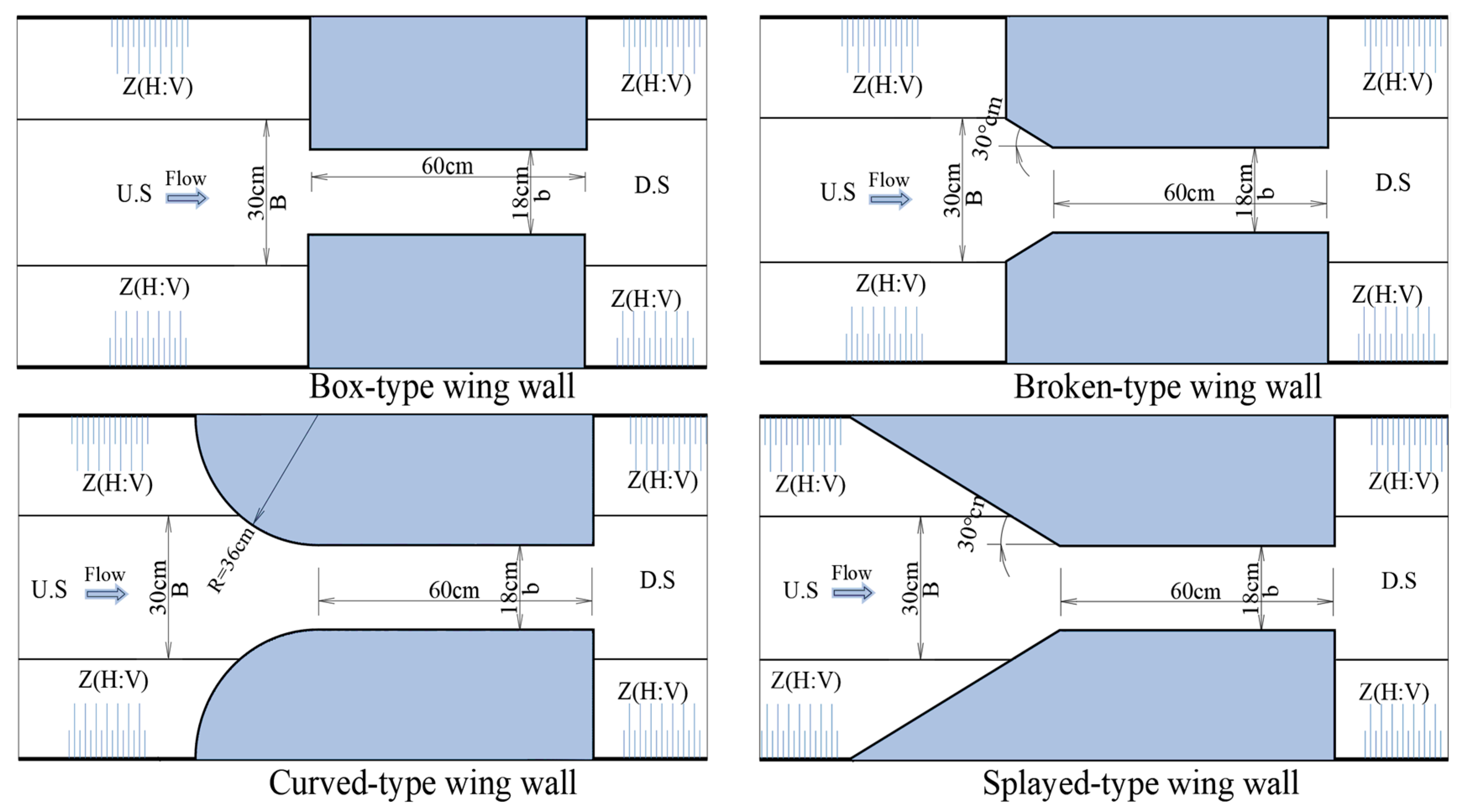
To address these gaps, the present study experimentally investigates the combined effects of four upstream wing wall geometries (box, broken, curved, and splayed) and three canal inside slope ratios (Z = H:V = 1:1, 3:2, and 2:1) through a total of 435 controlled laboratory experiments. The study aims to evaluate their combined effects on downstream scour characteristics, including scour depth and scour length, as well as the associated hydraulic behavior, to identify the most efficient configuration and develop empirical relationships applicable to practical field conditions.
2. Methods
2.1. Methodology
Considering the numerous interrelated variables that influence the hydraulic performance and scour behavior of water control structures, the investigation began with a comprehensive review of the most recent and widely recognized studies addressing these governing factors. A critical review of previous studies identified a key research gap. Based on this foundation, the experimental program was developed through careful selection and definition of the controlling variables, including movable bed characteristics, discharge range, wing wall geometries, canal inside slope ratios, and flow depths, supported by the adopted theoretical framework.
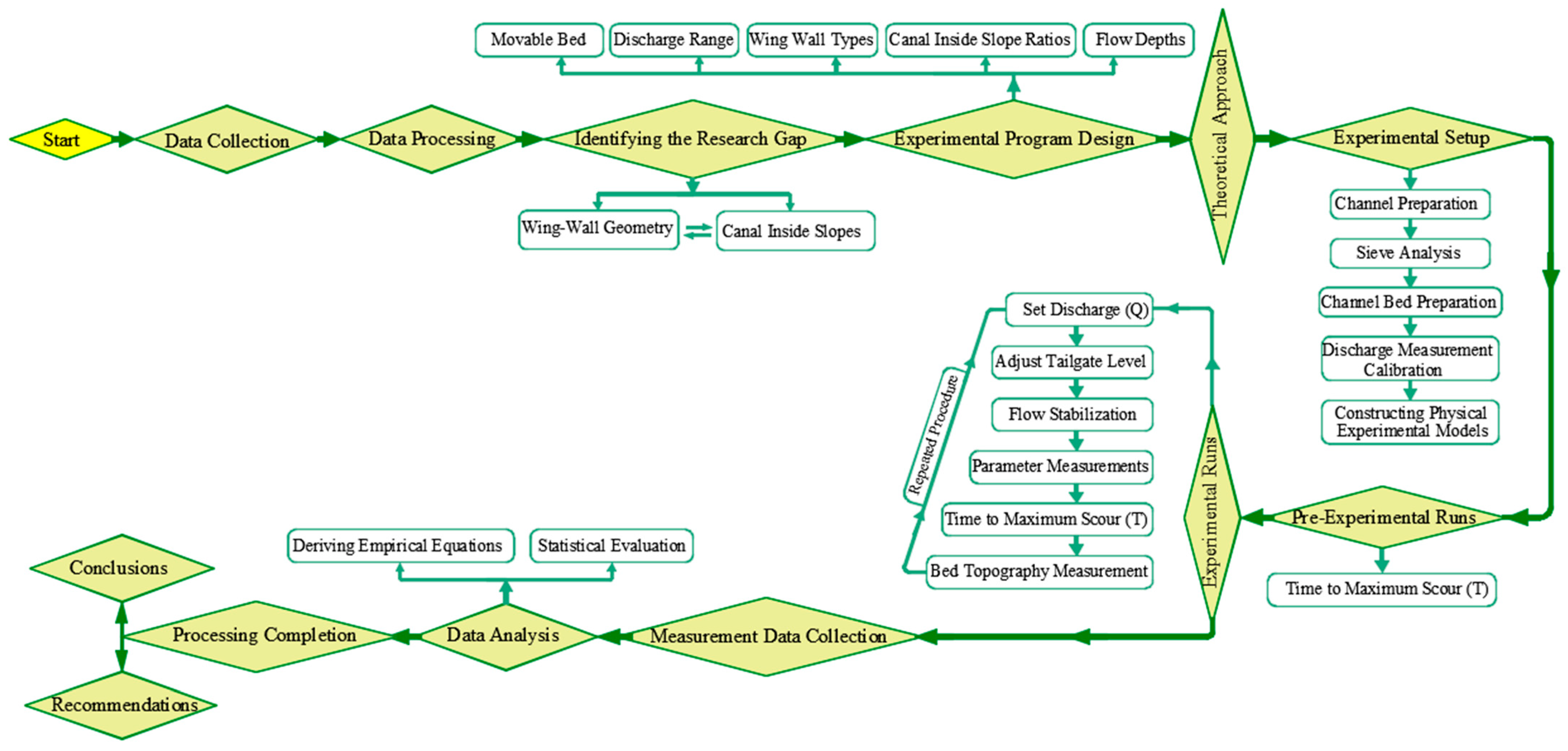
The overall methodological framework adopted for the experimental investigation, as illustrated in
Figure 1, presents the logical progression of the research from its conceptual stage to outcomes. The methodology progressed to the experimental setup stage, where the flume and channel were prepared with bed material arrangement through sieve analysis. Preliminary experimental runs were conducted to determine the time required to reach maximum scour depth, ensuring a suitable test duration. Subsequently, the main experimental runs were performed by systematically regulating discharge and tailgate levels, allowing flow stabilization, and conducting repeated measurements to ensure data accuracy and reliability. In the final stage, the collected data were organized and subjected to comprehensive statistical analysis, leading to the development of empirical equations, followed by the formulation of conclusions and recommendations within a coherent and integrated research workflow.
2.2. Dimensional Analysis
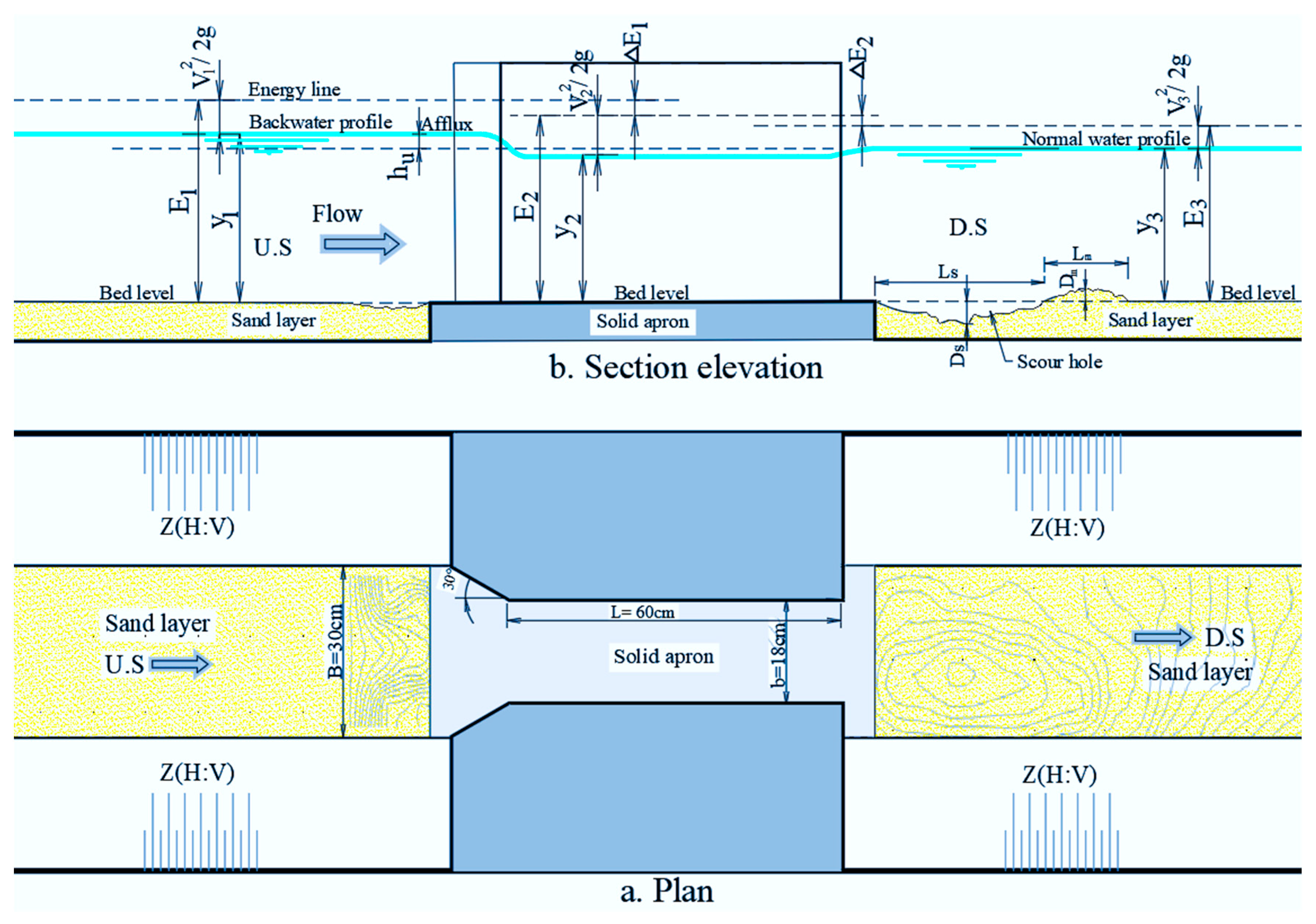
The variables that govern the hydraulic behavior and scour characteristics of the flow around the studied structure can be classified into fluid characteristics, geometric characteristics, flow characteristics, and sediment parameters. The fluid characteristics include the water density (ρ, kg/m
3), dynamic viscosity (μ, kg/ms), and surface tension (σ, kg/s
2). The geometric characteristics comprise the original channel width (B, m), the structure width (b, m), the upstream wing wall transition angle (θ, degree), the channel bed slope (S, m/m), the contraction ratio (r, m/m), the transition length (L, m), and the channel inside slope (Z = H:V). The flow characteristics are represented by the total energy loss (ΔE, m), upstream flow velocity (
, m/s), flow velocity through the structure (
, m/s), downstream flow velocity (
, m/s), gravitational acceleration (g, m/s
2), discharge (Q, m
3/s), upstream water depth (
, m), water depth through the structure (
, m), downstream water depth (
, m), and the afflux or heading-up (
, m). Finally, the sediment parameters include the density of the movable bed material (ρs, kg/m
3), the mean particle diameter (D
50, m), the scour depth (Ds, m), and the scour length (Ls, m), the scour width (Ws, m), sediment depth (D
m, m), and sediment length (L
m, m), all measured at a given time (T, s). A schematic representation of the experimental model, including all governing parameters considered in the study, is presented in
Figure 2.
Accordingly, the hydraulic parameters may be formulated as functions of the governing variables in the following general form:
Using Buckingham’s π theorem, Equation (1) is transformed into a dimensionless form (Equation (2)) by selecting
,
, and
as the repeating variables. These variables represent the fluid properties, flow inertia, and characteristic length scale at the structure entrance, span the fundamental dimensions (M, L, and T), and enable the derivation of dimensionless groups that govern the balance between inertial and gravitational forces.
where:
(Reynolds number),
(Froude number at the upstream section),
(discharge factor),
(Weber number),
r (contraction ratio). Then, Equation (2) can be written in the following form:
The influence of viscosity (μ) is considered negligible in the present analysis, as the flow is governed by gravitational forces. All experiments were conducted under fully turbulent conditions (Re > 10
4), where inertial forces significantly exceed viscous forces, and thus the effect of the Reynolds number becomes insignificant [
23].
Likewise, the effect of the Weber number is neglected, since surface tension forces are minimal under the present experimental conditions, particularly due to negligible temperature variations during the experimental runs. Furthermore, several geometric and hydraulic parameters were maintained constant throughout the experiments, including the channel bed slope (S ≈ 0), transition length (L), contraction ratio (r = 0.6), and upstream wing wall transition angle (θ = 30°) for both broken and splayed configurations.
Under these controlled conditions, the Froude number emerges as the primary governing dimensionless parameter for characterizing the flow regime in open-channel systems, as it represents the balance between inertial and gravitational forces. Accordingly, within the investigated subcritical flow range, it serves as the dominant controlling variable governing water surface behavior, flow stability, afflux, and energy dissipation.
Consequently, the general functional relationship governing hydraulic behavior under the four wing wall configurations and the three canal inside slope ratios may be expressed in the following dimensionless form:
The scour parameters may be formulated as functions of the governing variables in the following general form:
Applying Buckingham’s theorem with
,
, and
as repeating variables, the equations can be written in dimensionless form as:
The effects of fluid density and mean sand diameter are neglected, as a single fluid and one sediment type were used throughout the experiments. Also, the contraction ratio (r = b/B), and equilibrium scour time (T) were kept constant. Therefore, the following dimensionless form may be used to express the basic functional connection governing the downstream scour characteristics under the four wing wall configurations and the three canal inside slope ratios:
2.3. Experimental Setup
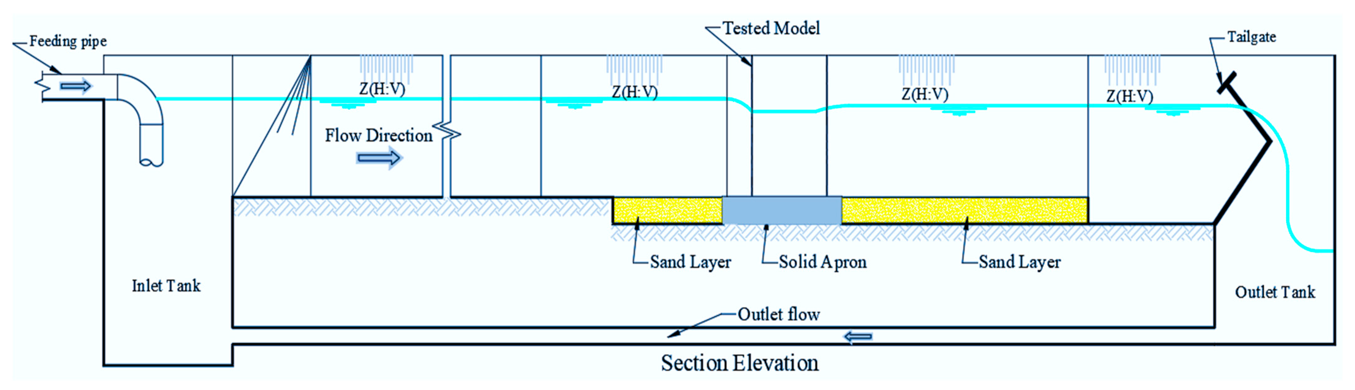
The experimental program was conducted in the Irrigation and Hydraulics Laboratory of the Civil Engineering Department at Assiut University, Egypt, utilizing a recirculating flume system. The experimental setup comprised a reinforced concrete horizontal channel with a trapezoidal cross-section, measuring 18.5 m in length, 0.88 m in bottom width, and 0.55 m in depth, with an internal side slope of 1:1. The bed width was designed as 0.30 m to facilitate the formation of three canal inside slope configurations (1:1, 3:2, and 2:1), in conjunction with four wing wall types constructed with a contraction ratio (r) of 0.60. Water circulation was maintained through a closed-loop system equipped with a constant-head tank to ensure stable and uniform flow conditions throughout the testing period.
A geometric scale ratio of 1:10 (model: prototype) was adopted to achieve geometric similarity while maintaining practical laboratory constraints. Dynamic similarity was ensured by preserving Froude number similarity, which governs free-surface flow behavior. Although complete similitude cannot be achieved due to scale effects associated with Reynolds number and sediment characteristics, these effects are considered negligible under fully turbulent flow conditions. A schematic representation of the experimental facility is presented in
Figure 3.
2.4. Bed Preparation and Soil Physical Properties
Before the experimental runs, the sediment bed was carefully leveled to ensure a uniform surface upstream and downstream of the tested model. The movable sediment bed extended 1.20 m upstream and 2.80 m downstream of the model, with a constant channel width of 0.30 m and a uniform sediment thickness of 0.20 m, as illustrated in
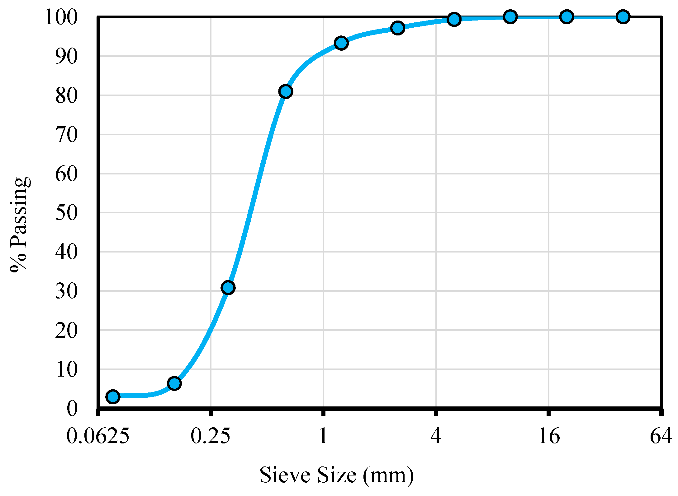
Figure 4. A sieve analysis was conducted to characterize the sand used in the experiments. The measured properties included specific gravity, unit weight, fineness modulus, fine content, uniformity, and median grain size. The experiments were performed under controlled laboratory conditions using clear water and uniformly graded sand with a median particle diameter of
. The sand exhibited a bulk unit weight of 1.64 t/m
3, a fineness modulus of 1.95, and a fine material content of 4.0%. The sediment gradation curve is shown in
Figure 5, illustrating the particle size distribution of the experimental sand.
Based on the particle size distribution curve, the characteristic grain diameters were determined as , , and . Accordingly, the calculated uniformity coefficient and curvature coefficient indicate that the sediment is poorly graded, representing a relatively uniform sand with a narrow particle size distribution. According to the Unified Soil Classification System (USCS), the tested material is classified as SP (poorly graded sand), as it contains less than 5% fines and does not meet the criteria for well-graded sand. Such uniform sediments are commonly used in laboratory-scale scour studies to ensure controlled and repeatable conditions, enabling clearer isolation of the effects of hydraulic and geometric parameters on scour development.
2.5. Experimental Condition and Tested Models
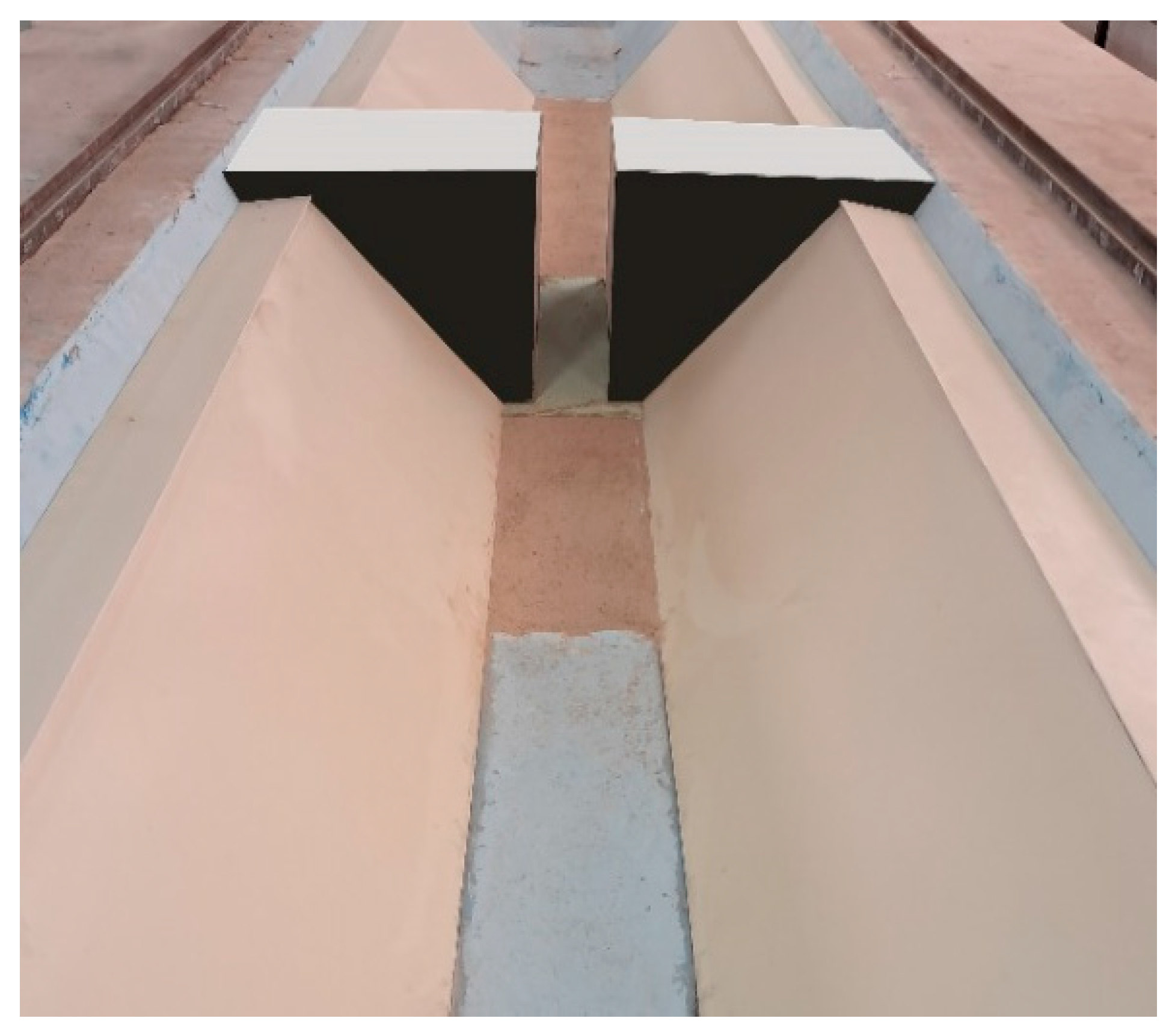
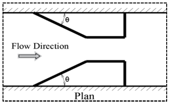
The experimental program comprised six calibrated discharges (5.46, 8.01, 13.01, 17.76, 21.78, and 24.90 L/s), with measurements conducted at five flow depths for each run. This arrangement enabled a systematic evaluation of the combined effects of wing wall geometry and canal inside slope on hydraulic behavior and scour development over a wide range of flow conditions. Four wing wall configurations (box, broken, curved, and splayed) were investigated in combination with three canal inside slope ratios (H:V = 1:1, 3:2, and 2:1), as illustrated in the definition sketch in
Figure 6. Overall, the experimental program consisted of 435 controlled laboratory experiments, covering all combinations of geometry, slope, and hydraulic conditions.
2.6. Measurements and Accuracy
The flow rate was determined using an orifice meter connected to a manometer installed on the supply pipe. The readings of the orifice meter were validated through their comparison with the calculated discharges using a V-notch weir, which was adopted as the reference method. The close agreement between the two techniques confirmed the accuracy and reliability of the measured flow rates for all experimental runs. The tailgate was adjusted to achieve the target downstream (D.S.) water depth corresponding to each flow condition. Before measurements’ acquisition, the system was allowed to stabilize until a constant water level was attained, thereby ensuring the establishment of steady-state flow conditions. Hydraulic measurements were carried out using an electrical point gauge with an accuracy of ±0.1 mm. Water depths were recorded three times at each measurement location, and the mean values were used to enhance data reliability. This measurement protocol was consistently applied to all experimental configurations, including the different wing wall geometries (box, broken, curved, and splayed types) with different canal inside slope ratios (1:1, 3:2, and 2:1), ensuring methodological uniformity throughout the experimental program. After each experimental run, the channel was drained, and the bed topography of the sand layer was surveyed. Bed elevations were measured at 0.05 m intervals across the channel width and at 0.05 m intervals along both the upstream and downstream reaches. Based on these measurements, contour maps of the bed surface were generated using the Surfer software (Version 19.1.189), from which the maximum scour depth and scour length were determined and plotted.
An uncertainty analysis was carried out for all measured and derived variables to ensure the accuracy and reliability of the experimental data. Water depths were measured at three repeated lateral points using an electrical point gauge with an accuracy of ±0.1 mm. Measured depths ranged from 12.5 to 25.5 cm, resulting in relative measurement uncertainties of ±0.04–0.08%.
Error-propagation analysis was applied to the main dimensionless hydraulic parameters. The propagated uncertainties were ±0.76% for relative energy loss (), ±0.69% for relative heading-up (/), ±0.68% for relative water depth (), and ±1.22% for the velocity ratio (). These uncertainty levels are within acceptable limits for laboratory-scale hydraulic experiments. Statistical analysis was performed using a two-way analysis of variance (ANOVA) to evaluate the effects of upstream wing wall configuration and canal inside slope on the hydraulic and scour parameters. A significant level of α = 0.05 was adopted for all experiments.
3. Results
The working efficiency of water structures is governed by the complex interaction between flow behavior and sediment response. The degree of flow obstruction introduced by the structure plays a pivotal role in controlling both the hydraulic characteristics of the approaching and downstream flow and the associated scouring processes. On one hand, minimizing flow obstruction enhances hydraulic efficiency by reducing heading-up, regulating flow velocity and water depth, and limiting entrance energy losses. On the other hand, structural safety is closely linked to scouring characteristics, which are influenced by changes in flow patterns induced by variations in structural geometry and upstream wing wall configurations. These variations modify downstream velocity and turbulence, thereby controlling the depth and extent of scour development. Consequently, achieving reduced scour dimensions is essential for improving structural stability, operational efficiency, and long-term sustainability through minimizing maintenance requirements.
3.1. Hydraulic Flow Behavior
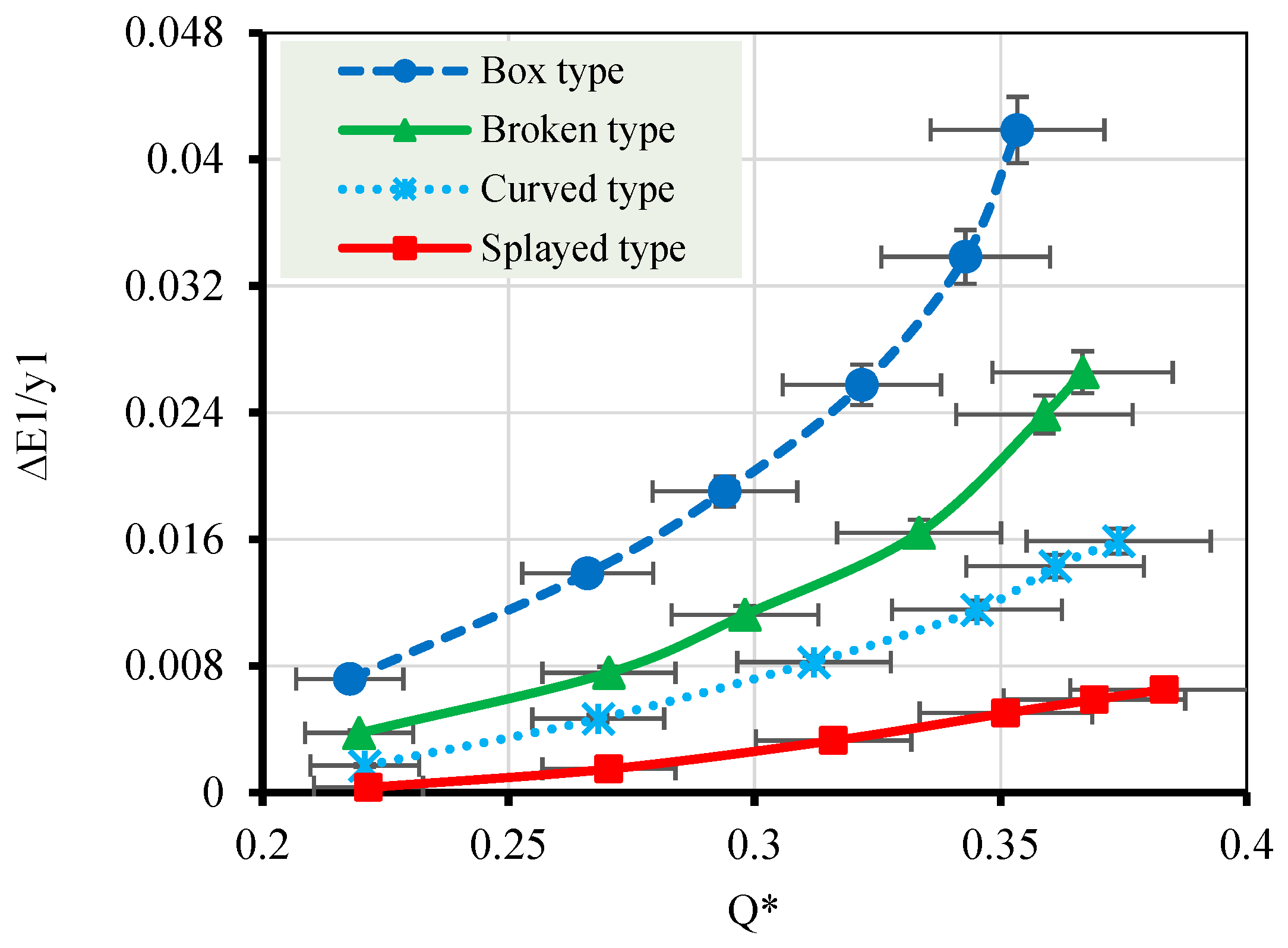
Minimizing energy losses is essential for ensuring smooth flow transitions, reducing turbulence intensity, and limiting adverse backwater effects. The present results indicate that these objectives can be effectively achieved through an appropriate combination of upstream wing wall geometry and canal inside slope. As shown in
Figure 7, analysis of the relationship between the relative upstream energy loss (
/
) and the discharge factor (Q*) reveals a clear positive correlation for all tested configurations, confirming that increasing flow intensity leads to higher entrance energy losses.
Among the wing wall types investigated, the splayed configuration consistently exhibited the most favorable hydraulic efficiency, achieving the lowest relative energy losses over the examined discharge range. The splayed wing wall reduced entrance energy losses by approximately 84.12% relative to the conventional box-type configuration at a canal inside slope of Z = 1:1 under identical hydraulic conditions, with low variability as indicated by the associated error bars. This enhanced performance is primarily attributed to the gradual flow expansion associated with the splayed geometry, which promotes smoother streamline alignment, suppresses flow separation, and limits vortex formation at the entrance.
The increase in relative energy loss with increasing is attributed to the intensification of flow–structure interaction and associated turbulence mechanisms. Higher discharge enhances the upstream downflow, which strengthens the horseshoe vortex system at the bed, leading to increased turbulent mixing and bed shear stress. These processes significantly contribute to energy dissipation and are consistent with established scour mechanics. The higher energy loss observed for the box type is linked to sharp-edge-induced flow separation and stronger vortex formation, whereas smoother geometries (curved and splayed) reduce separation and turbulence intensity, resulting in lower energy dissipation.
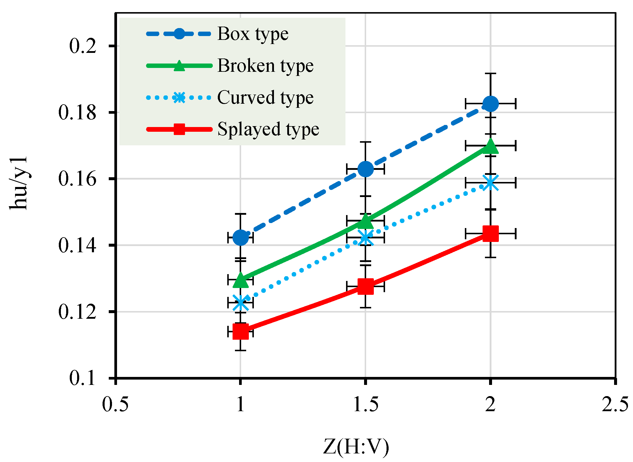
The influence of the canal inside slope was also pronounced. For all wing wall configurations, minimum energy losses were observed at a canal inside slope of 1:1, whereas maximum losses occurred at a slope of 2:1, highlighting the critical role of channel geometry in energy conservation. Similar trends were identified for afflux generation (
Figure 8), where the relative afflux (hᵤ/y
1) increased steadily with increasing upstream Froude number. The box-type wing wall produced the highest afflux values due to severe flow contraction at the entrance. In contrast, the splayed configuration achieved an average reduction in afflux of approximately 30.01% relative to the conventional box-type design at a canal inside slope of Z = 1:1, under identical hydraulic conditions, with low variability as indicated by the associated error bars. Regardless of wing wall geometry, the lowest afflux values were consistently recorded at a 1:1 canal inside slope, confirming the combined and interactive influence of entrance geometry and canal inside slope on overall hydraulic performance, which is consistent with the results of the previous numerical study by [
7].
The increase in relative heading-up with increasing side slope is mainly governed by changes in flow structure and resistance. A larger slope induces gradual flow expansion and generates secondary currents, leading to non-uniform velocity distribution and increased shear stress along the boundaries. This results in higher energy losses and, consequently, greater upstream water depth. From a scour perspective, these changes affect shear stress distribution and sediment transport potential. The box configuration shows higher heading-up due to stronger flow separation, while smoother transitions in curved and splayed types reduce vortex formation and hydraulic resistance.
As illustrated in
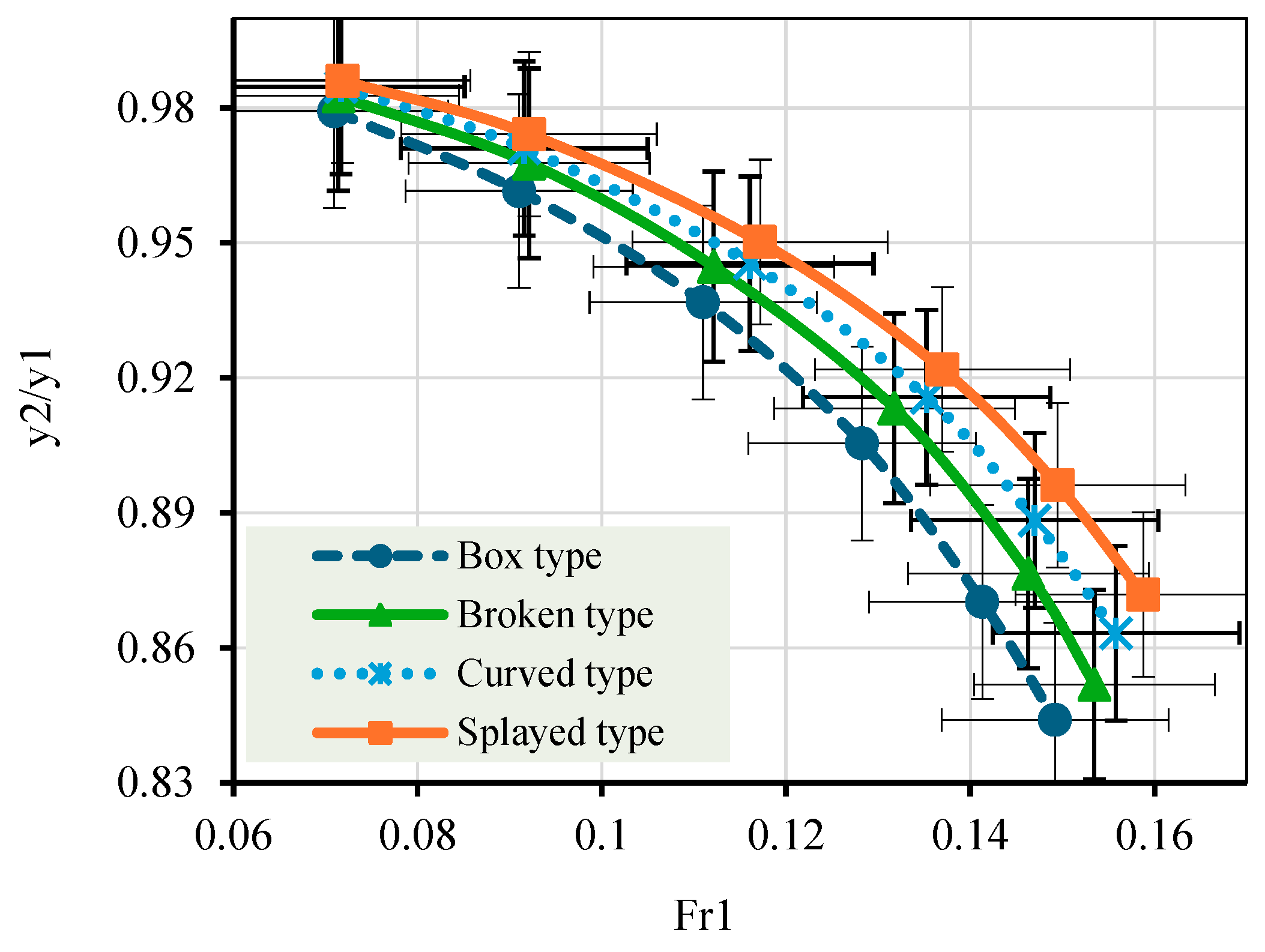
Figure 9, the relative water depth ratio (y
2/y
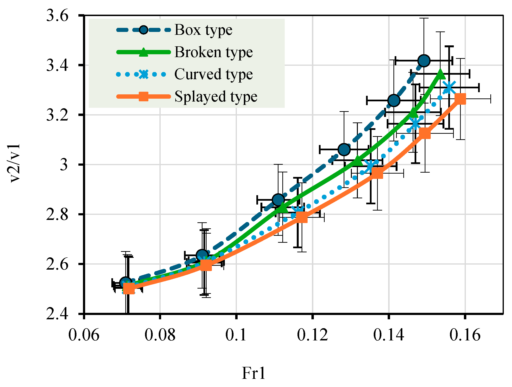
1) decreases progressively with increasing upstream Froude number, reflecting the growing dominance of kinetic energy over potential energy as flow intensity increases. Conversely, the relative velocity ratio (v
2/v
1) exhibits a consistent increasing trend with the upstream Froude number, as shown in
Figure 10, indicating flow acceleration downstream of the structure entrance.
Among the examined configurations, the box-type wing wall consistently produced the highest velocity ratios and the largest variations in relative water depth. This behavior is attributed to the abrupt flow contraction associated with this geometry, which intensifies turbulence and results in less stable depth conditions. In contrast, the splayed wing wall maintained more uniform water depth ratios and comparatively lower velocity amplification, demonstrating superior hydraulic efficiency and smoother flow transitions.
On average, splayed-type entrances exhibited reduced flow contraction and more gradual energy redistribution, leading to noticeably lower afflux and improved depth uniformity. Overall, the results confirm that optimal hydraulic performance is achieved by combining splayed upstream wing walls with a mild canal inside slope of 1:1. This configuration effectively minimizes energy losses and afflux, promotes uniform flow distribution, and reduces turbulence intensity, thereby improving operational efficiency and supporting the long-term sustainability of canal-based water conveyance systems.
3.2. Scour Behavior
3.2.1. Determination of Equilibrium Scour Time (T)
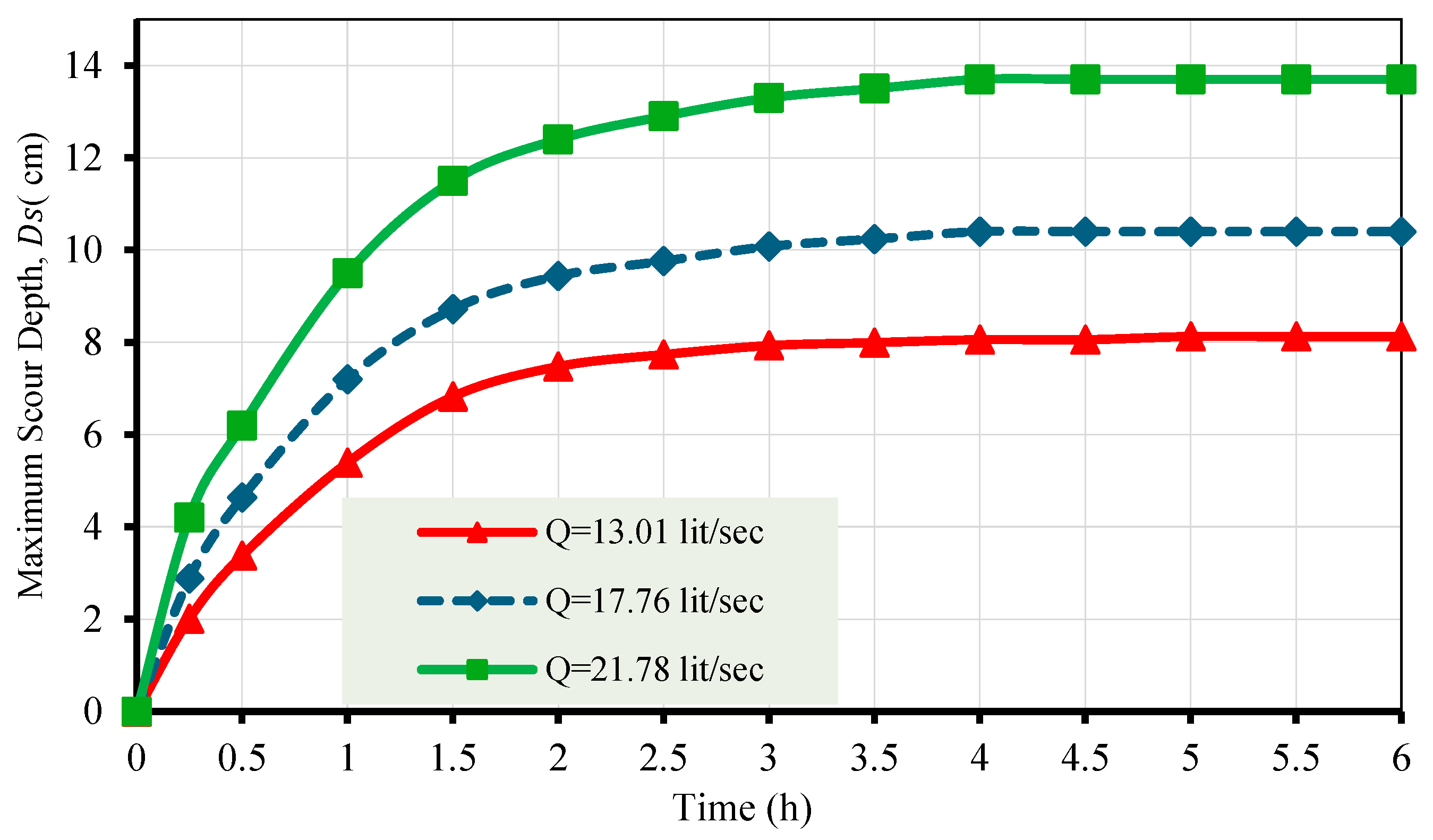
The temporal evolution of the maximum scour depth
under three representative discharges
is presented in
Figure 11. As shown, scour depth increases rapidly during the initial stage of flow, reflecting the high sediment mobility and intense bed erosion immediately after flow initiation. This initial phase is followed by a gradual reduction in the rate of scour development as sediment transport decreases and the bed morphology begins to stabilize.
To quantitatively define equilibrium conditions, a stability criterion was adopted whereby equilibrium is considered to be achieved when the variation in scour depth is less than 1% over successive time intervals. Based on the experimental data, it was found that after approximately 4 h, the temporal variation in was consistently less than 1% for all tested discharges.
Accordingly, the scour curves asymptotically approach a constant value after approximately 4 h, indicating the attainment of equilibrium scour conditions. Beyond this duration, additional increases in time result in negligible changes in scour depth. Based on these observations, an equilibrium time of 4 h was adopted for all subsequent experiments to ensure that the measured scour depths represent fully developed and stable conditions.
3.2.2. Bed Topography and Longitudinal Profiles
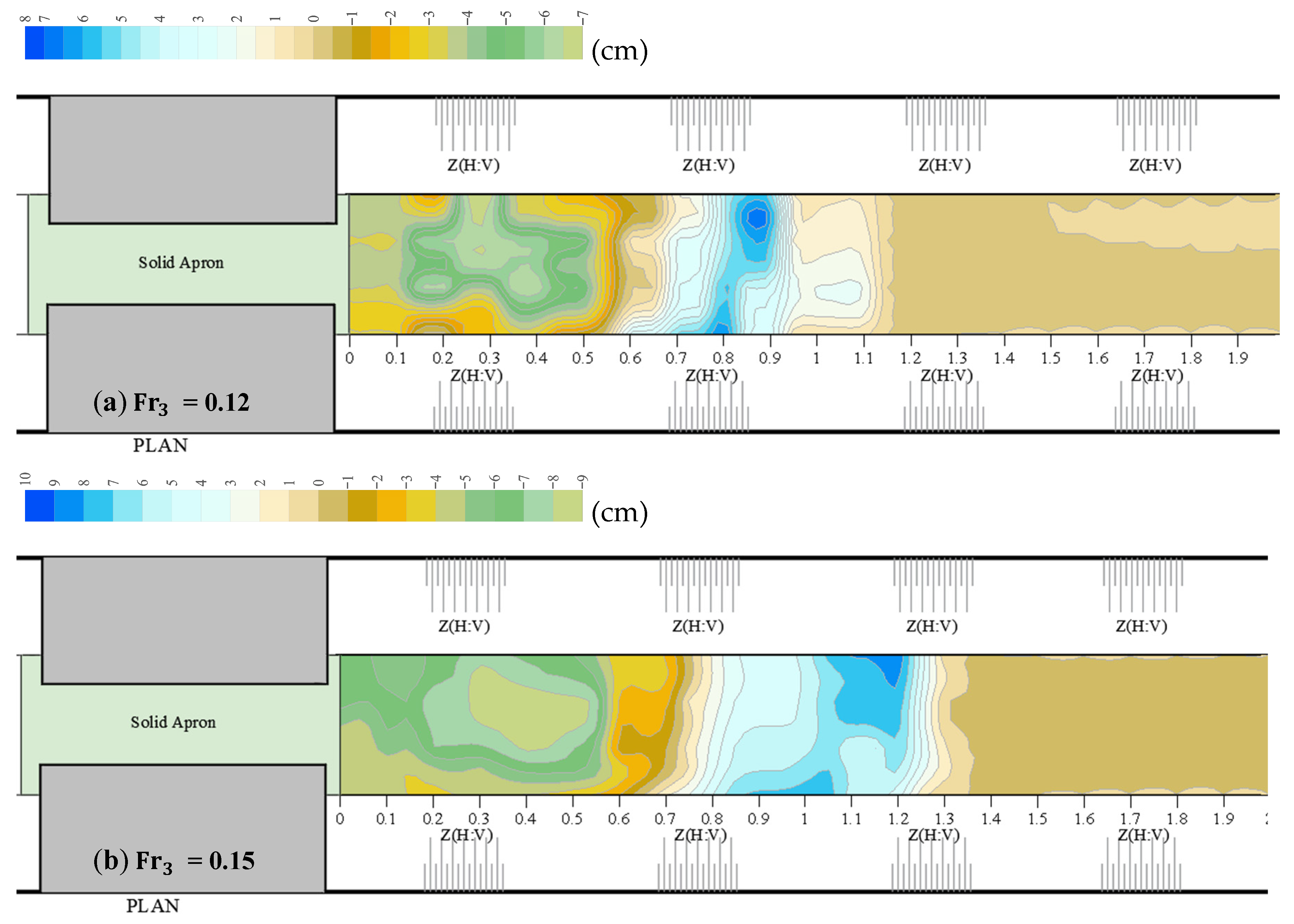
A careful investigation of bed topography and scour features is required to create efficient scour mitigation strategies. Following each experimental run, a systematic grid-based survey of the canal bed was performed, and the observed bed elevations were processed and displayed using Surfer software to provide detailed bed topography maps and scour contours.
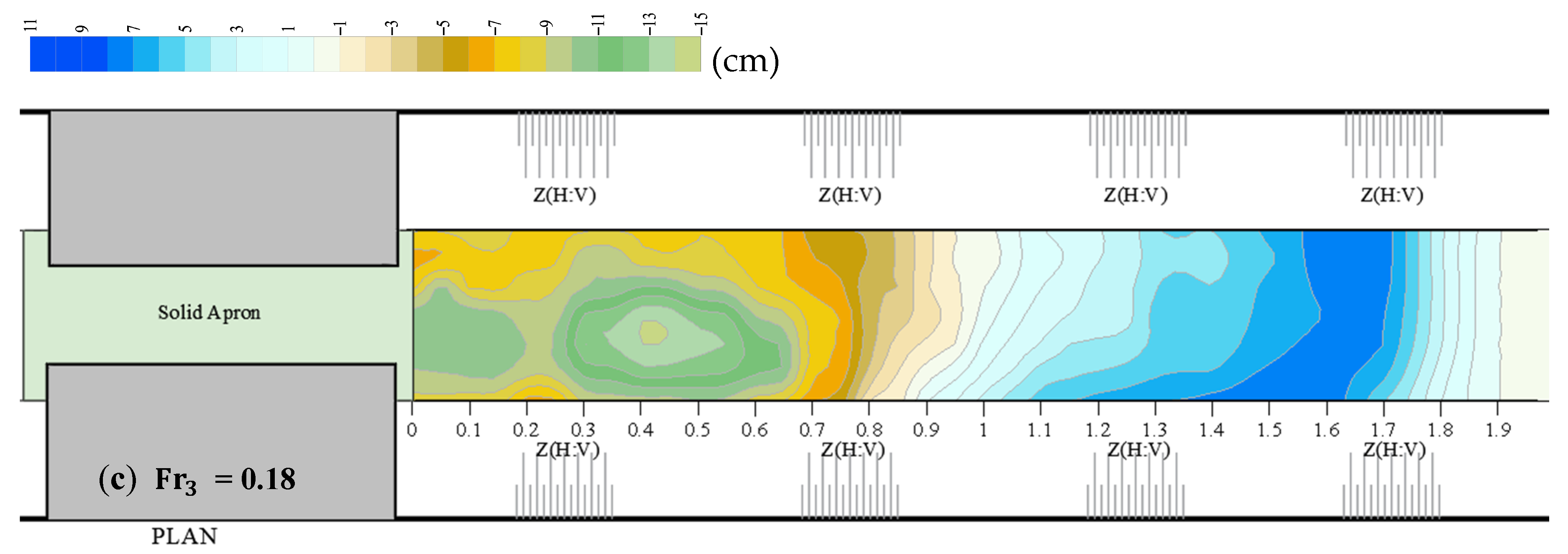
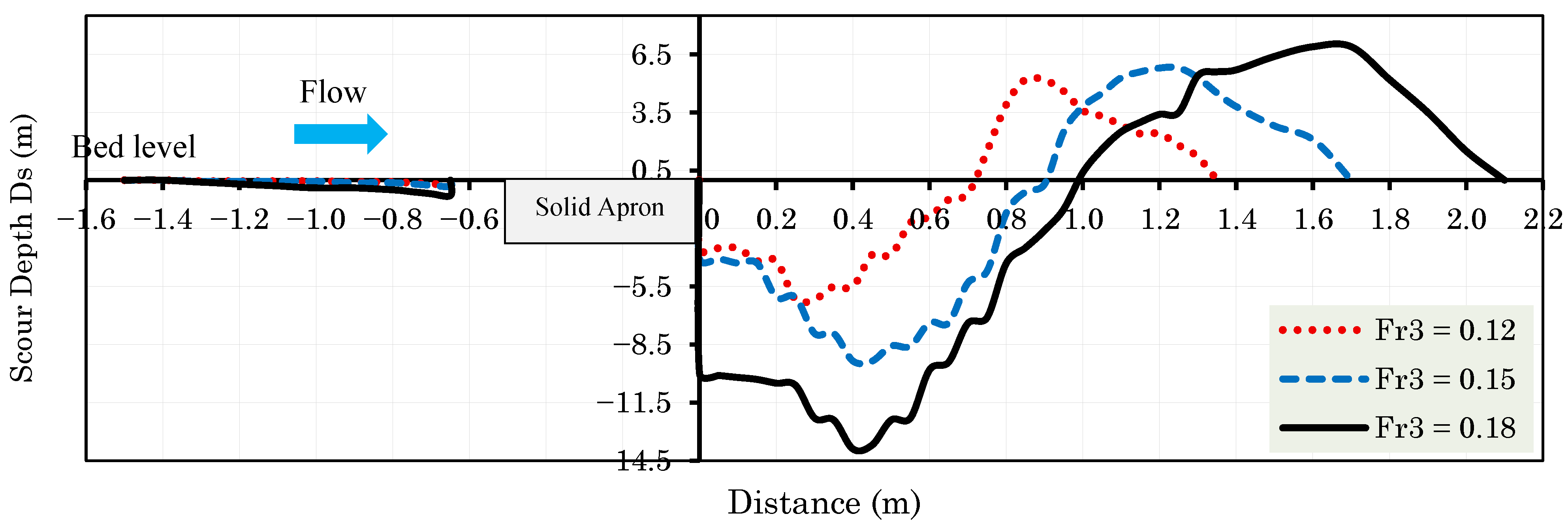
Figure 12 illustrates the evolution of bed topography downstream of the box-type wing wall with a canal inside slope of Z = 1:1 under three upstream Froude numbers (Fr
3 = 0.12, 0.15, and 0.18). At the lowest Froude number (Fr
3 = 0.12), the bed morphology exhibits relatively mild scour features characterized by shallow scour depths and limited spatial extent, indicating weak flow sediment interaction and low turbulence intensity. As the Froude number increases to 0.15, the scour hole becomes more pronounced and elongated, with steeper bed gradients forming near the structure entrance, reflecting increased flow acceleration and enhanced sediment entrainment.
At the highest tested Froude number (Fr3 = 0.18), the bed topography reveals a significantly deeper and wider scour hole extending further downstream, accompanied by stronger bed deformation and sharper contour gradients. This behavior is attributed to the intensified flow contraction and elevated turbulence levels associated with higher flow energy, which increase bed shear stress beyond the critical threshold for sediment motion. Overall, the progressive deepening and expansion of the scour hole with increasing Froude number confirms the dominant role of flow intensity in governing scour development. These observations further highlight the susceptibility of box-type wing wall configurations to severe scour under high-flow conditions, emphasizing the need for optimized entrance geometries to mitigate bed degradation and enhance structural safety.
As an example,
Figure 13 illustrates the influence of the Froude number (Fr
3) on the longitudinal bed profiles downstream of the structure at a canal inside slope of Z = 1:1 with a box-type wing wall. The depth and longitudinal extent of the scour hole increase significantly with increasing Froude number, reflecting the increased erosive potential of the flow. Higher Fr
3 values intensify bed shear stresses and turbulence levels near the structure, thereby promoting sediment entrainment and shifting the location of maximum scour further downstream.
In addition to the deepening and elongation of the scour hole, the characteristics of the downstream deposition zone are also markedly affected. As the Froude number increases, both the height and longitudinal extent of the deposition mound grow noticeably. This behavior results from the redistribution of entrained sediments transported from the scour region and their subsequent deposition where velocities and shear stresses decrease. The rapid decay of flow momentum downstream of the maximum scour point reduces the local sediment transport capacity, facilitating sediment settling and the formation of more pronounced deposition mounds.
Overall, these observations confirm that the Froude number governs not only the intensity of scour but also the geometry of the associated deposition patterns, thereby controlling the overall downstream bed morphology.
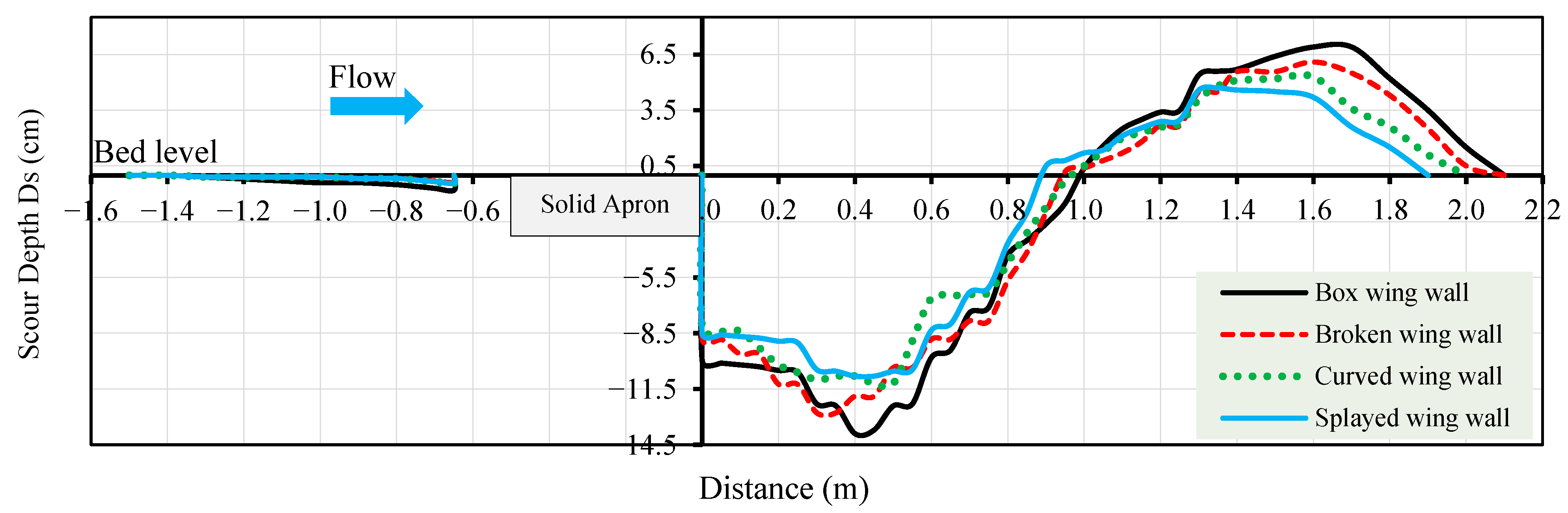
The longitudinal bed profiles downstream of the structure corresponding to different upstream wing wall configurations (box, broken, curved, and splayed) at Fr
3 = 0.18 and a canal inside slope of Z = 1:1 are illustrated in
Figure 14. The bed elevation is referenced to the initial bed level, where negative values represent scour, and positive values indicate deposition. Upstream bed variations are negligible relative to the pronounced downstream scour region. A distinct scour hole forms immediately downstream of the apron edge, with the box-type wing wall generating the deepest and most abrupt scour due to intensified flow contraction and turbulence.
The broken and curved wing wall configurations exhibit moderate reductions in the scour depth and smoother bed profiles, indicating partial mitigation of flow separation and the associated energy losses. The broken configuration achieves reductions in the maximum scour hole depth and length of approximately 10.32% and 10.92%, respectively, reflecting a moderate improvement in flow guidance and energy dissipation. More pronounced reductions of about 17.06% in scour depth and 16.71% in scour length are observed for the curved wing wall configuration, which can be attributed to its enhanced ability to streamline the incoming flow, reduce flow separation, and weaken the intensity of erosion downstream of the structure.
In contrast, the splayed wing wall configuration demonstrates the most favorable behavior, generating the shallowest scour depth and the smoothest bed recovery. When combined with a 1:1 canal inside slope, the splayed wing wall reduced the maximum scour depth and scour hole length by up to 22.74% and 23.61%, respectively, compared with the box-type configuration. Further downstream, the scour hole transitions into a deposition zone, and the use of the box-type configuration produces the most pronounced deposition due to higher sediment transport rates. Overall, the results highlight the critical role of wing wall geometry in controlling scour development and bed stability under high-flow conditions.
The scour hole downstream of the apron is mainly driven by the impinging downflow and the resulting horseshoe vortex, which increases bed shear stress and sediment removal at this location. The box wing wall shows the deepest scour due to strong flow separation and intensified vortex structures, while curved and splayed configurations reduce separation and weaken vortices, leading to shallower scour. The downstream recovery zone reflects the decay of vortex strength and reduced shear stress. Overall, the results confirm that scour development is governed by vortex dynamics and flow–structure interaction rather than only geometric variation.
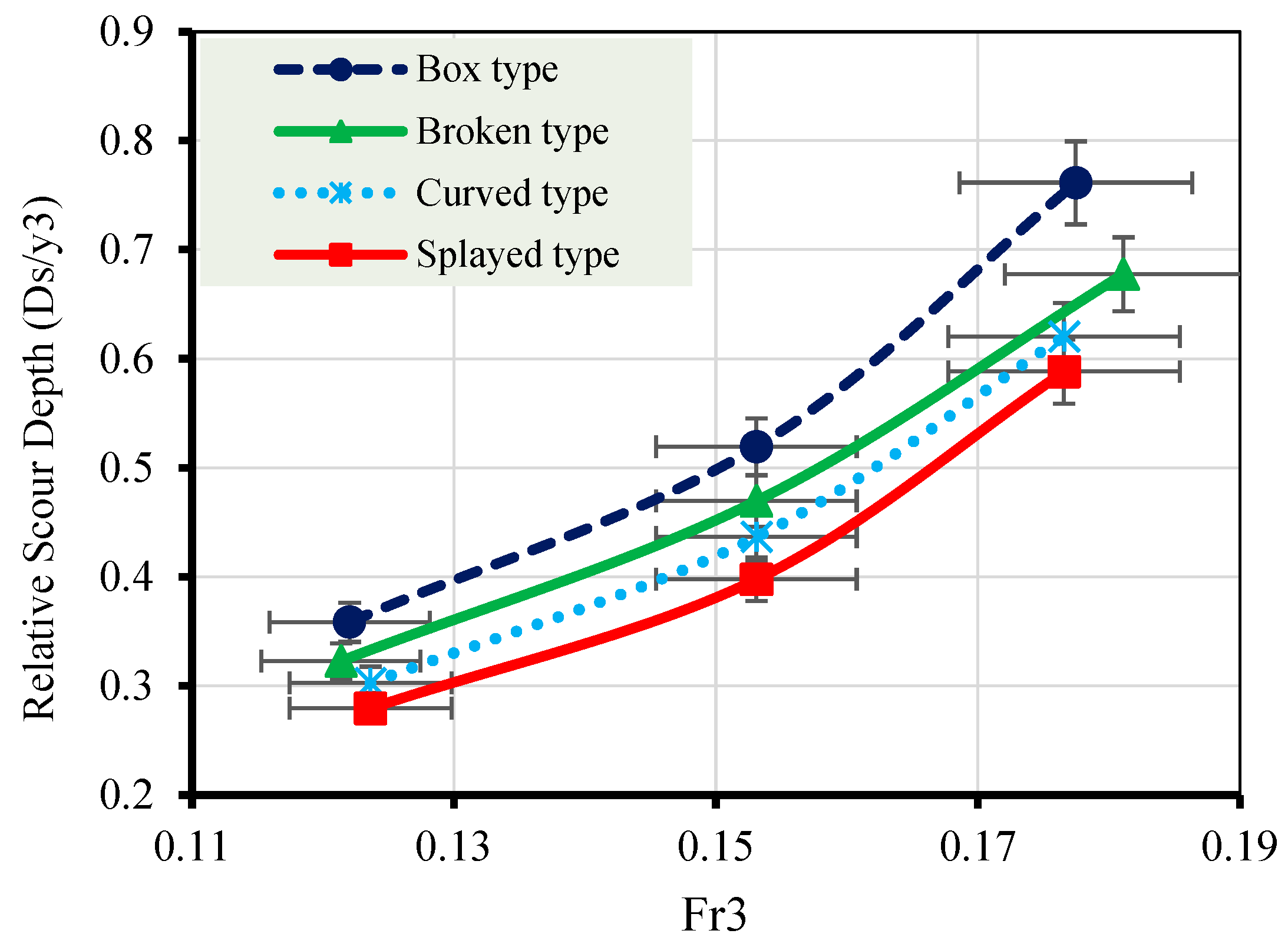
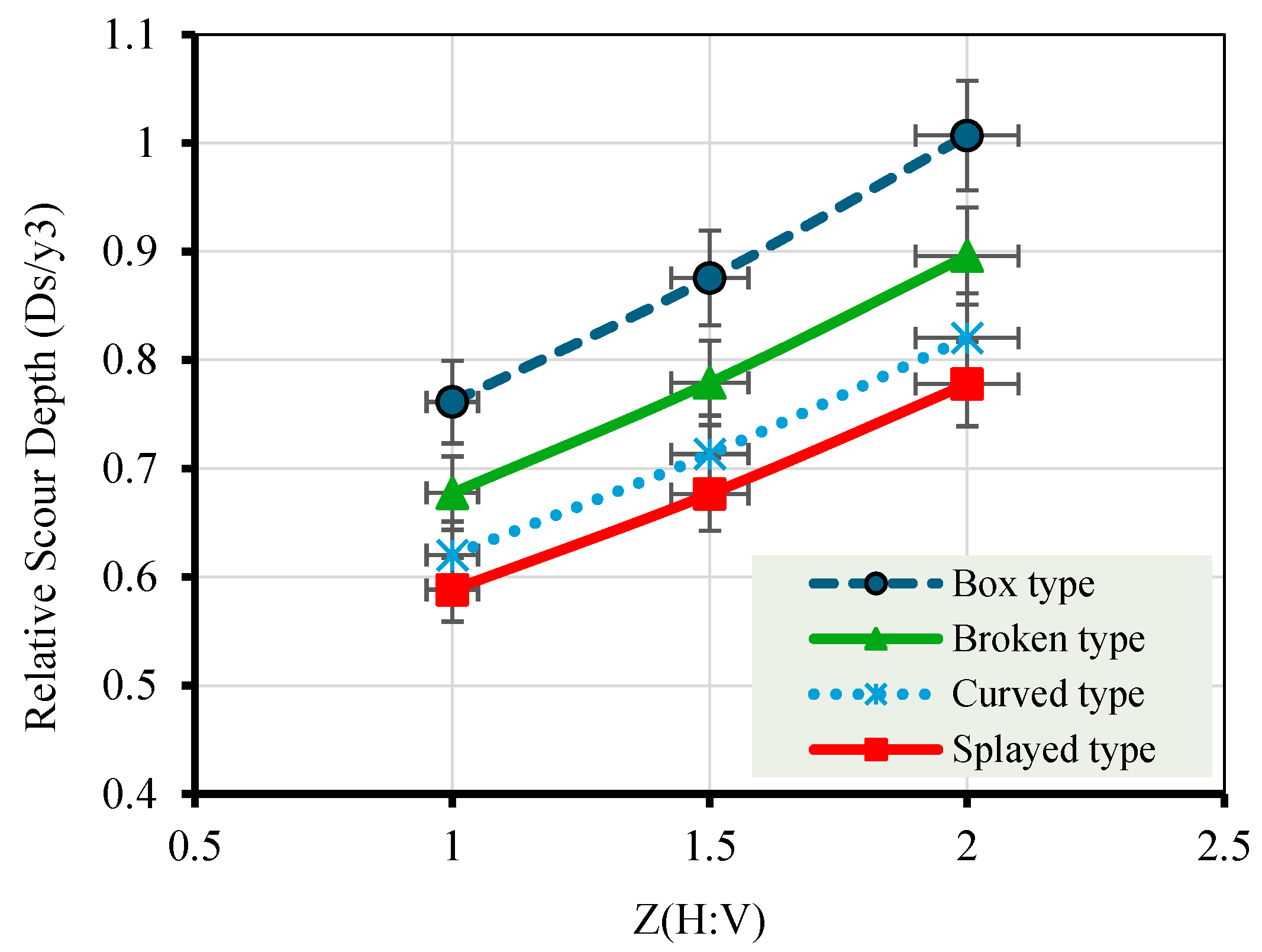
The combined results presented in
Figure 15 and
Figure 16 demonstrate that the relative scour depth (Ds/y
3) is strongly influenced by both the downstream Froude number (Fr
3) and the canal inside slope (Z). An increase in Fr
3 leads to a systematic increase in scour depth for all wing wall configurations, reflecting the enhanced kinetic energy, turbulence intensity, and bed shear stress associated with higher flow velocities downstream of the structure. Similarly, increasing the inside slope of the canal intensifies flow confinement and momentum transfer toward the downstream bed, resulting in higher erosive forces and deeper scour formation. In all cases, the box-type wing wall produces the maximum scour depth due to abrupt flow expansion and strong flow separation, which generate pronounced recirculation zones and elevated turbulence levels. Conversely, the curved and splayed configurations consistently exhibit lower scour depths, as their streamlined geometries promote smoother flow transition and reduce velocity gradients more gradually. The consistent ranking of scour severity across varying flow intensities and channel slopes highlights the dominant role of wing wall geometry in controlling downstream scour. These findings emphasize that effective scour mitigation can be achieved through appropriate geometric design, particularly under high Froude number conditions and steeper canal slopes, thereby enhancing structural stability and long-term hydraulic performance.
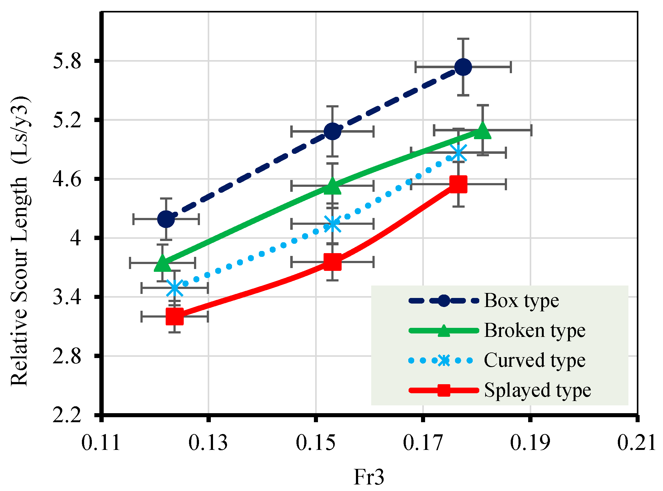
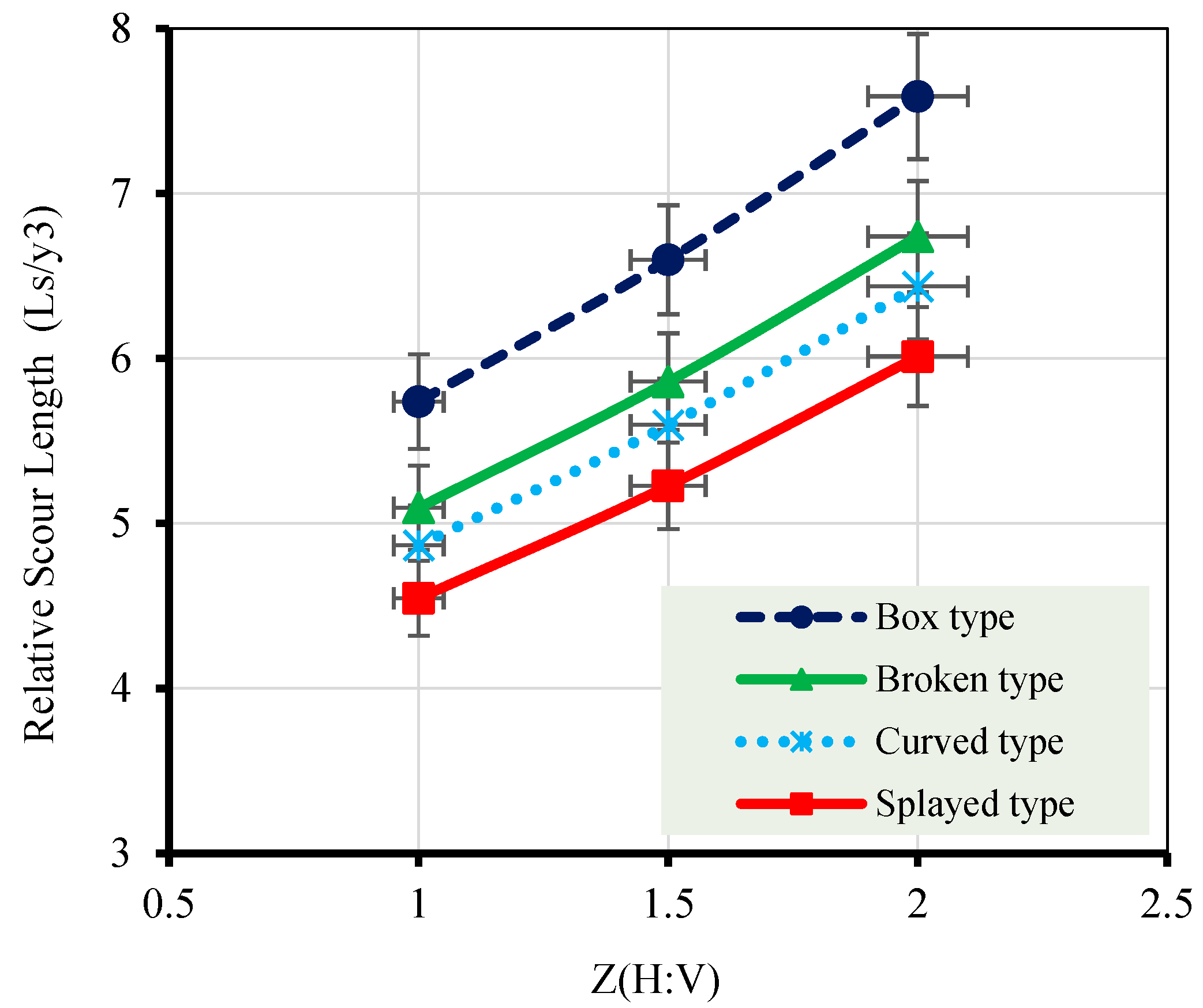
To further investigate the combined influence of hydraulic intensity and channel geometry on downstream bed morphology, the variation in relative scour length is examined in detail. The results presented in
Figure 17 and
Figure 18 demonstrate that the relative scour length (Ls/y
3) increases consistently with increasing downstream Froude number (Fr
3) and canal inside slope (Z) across all wing wall configurations. Higher Fr
3 values are associated with increased flow momentum and shear stress at the bed, leading to enhanced sediment entrainment and a progressive downstream extension of the scour hole.
Consequently, the zone affected by erosion extends farther downstream as flow momentum increases. Similarly, steeper canal inside slopes intensify flow confinement and accelerate the approach flow toward the structure, resulting in greater momentum transfer and sustained erosive action over a longer downstream distance. The box-type wing wall consistently produces the longest scour lengths due to abrupt flow contraction and expansion, which generates strong recirculation zones and prolonged turbulence downstream. In contrast, curved and splayed configurations effectively reduce scour length by providing smoother flow transitions and more gradual energy losses. This reduction in scour extent corresponds closely with the lower afflux and heading-up values observed for streamlined wing wall geometries, indicating reduced upstream energy losses and improved hydraulic efficiency. The strong agreement between trends in scour length, scour depth, afflux, and heading up confirms that downstream bed response is hydraulically coupled with upstream flow behavior. From an engineering perspective, optimizing wing wall geometry not only controls rising upstream water level but also significantly reduces both the depth and spatial extent of the downstream scour hole, thereby enhancing the structural safety and long-term performance of the water structure.
3.3. Introduced New Empirical Relationships
Empirical mathematical relationships for the quick prediction of scour behavior were developed using experimental data from every investigated configuration. In order to maximize scour resistance downstream of the structure, the suggested equations offer useful design tools to help water-structure designers choose the best upstream wing wall shape and canal inside slope. These relationships allow for the accurate estimation of scour length and depth for water structures with different canal inside slopes and wing wall geometries. Multiple linear regression serves as the foundation for the predictive equations with its general form:
where Z is the canal inside slope ratio (H:V),
is the downstream Froude number, Y is the dimensionless hydraulic parameter, and a, b, and c are unique empirical coefficients for each type of wing wall. The linear regression formulations were adopted because the scour relationships, presented in
Figure 15,
Figure 16,
Figure 17 and
Figure 18, exhibited approximately linear trends within the studied hydraulic range. In addition, several statistical analyses, including coefficients of determination (R
2), RMSE values, residual analysis, and significance tests, confirmed the adequacy and reliability of the adopted models. Therefore, the linear formulations were considered sufficiently accurate, practically applicable, and suitable for representing the investigated scour behavior. Based on experimental data, the specific equations can be expressed as follows:
Table 2 includes the full set of empirical coefficients (a, b, and c) for each type of wing wall, allowing designers to choose the right values depending on the canal inside slopes ratio and particular structural wing wall geometry.
The statistical results presented in
Table 3 collectively demonstrate the strong predictive capability of the developed empirical relationships. The regression models exhibit high coefficients of determination (R
2 = 0.957–0.998) and very small
p-values, confirming their statistical significance and robustness. The narrow 95% confidence intervals further indicate stable and reliable regression coefficients. As shown in
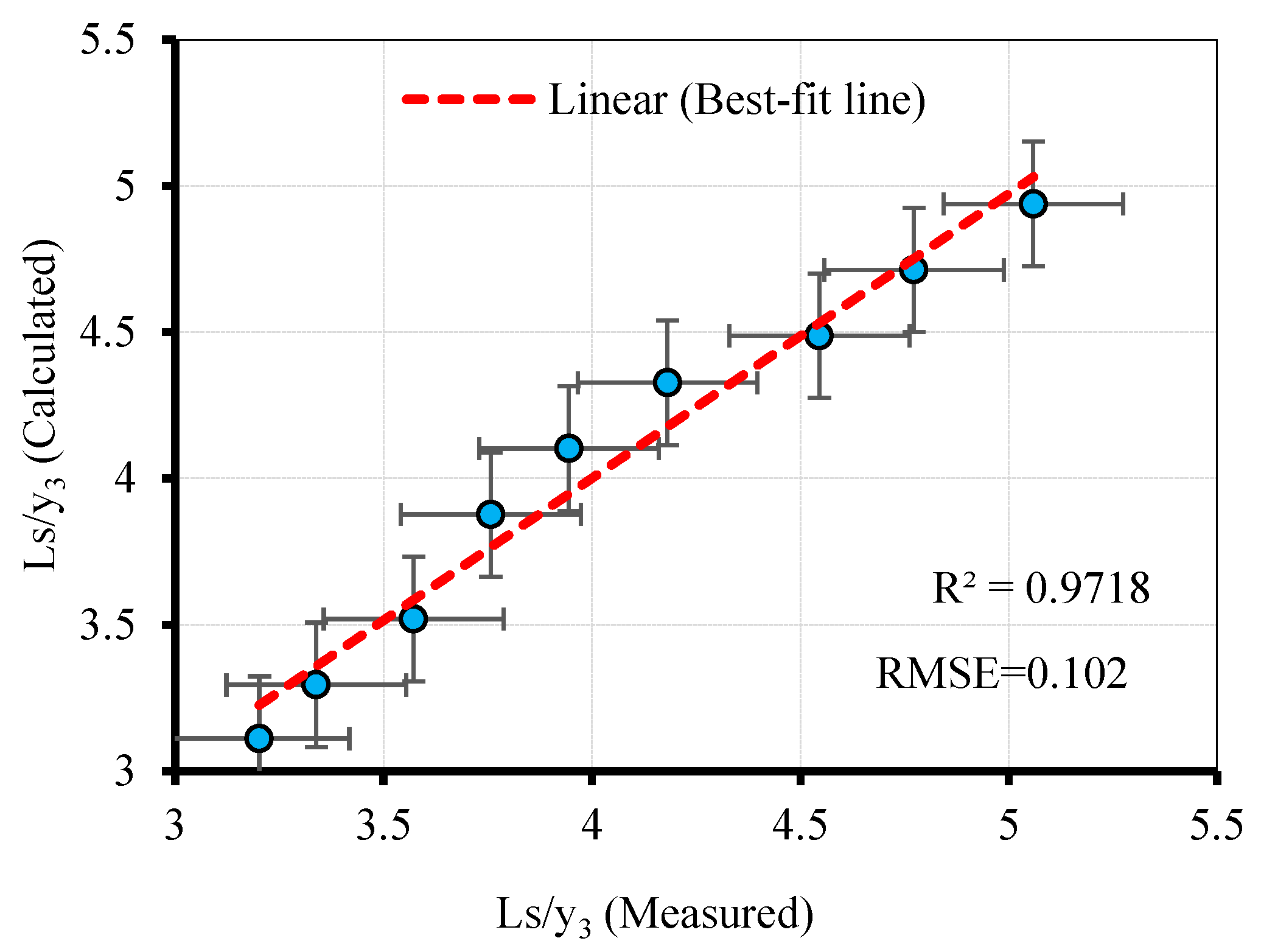
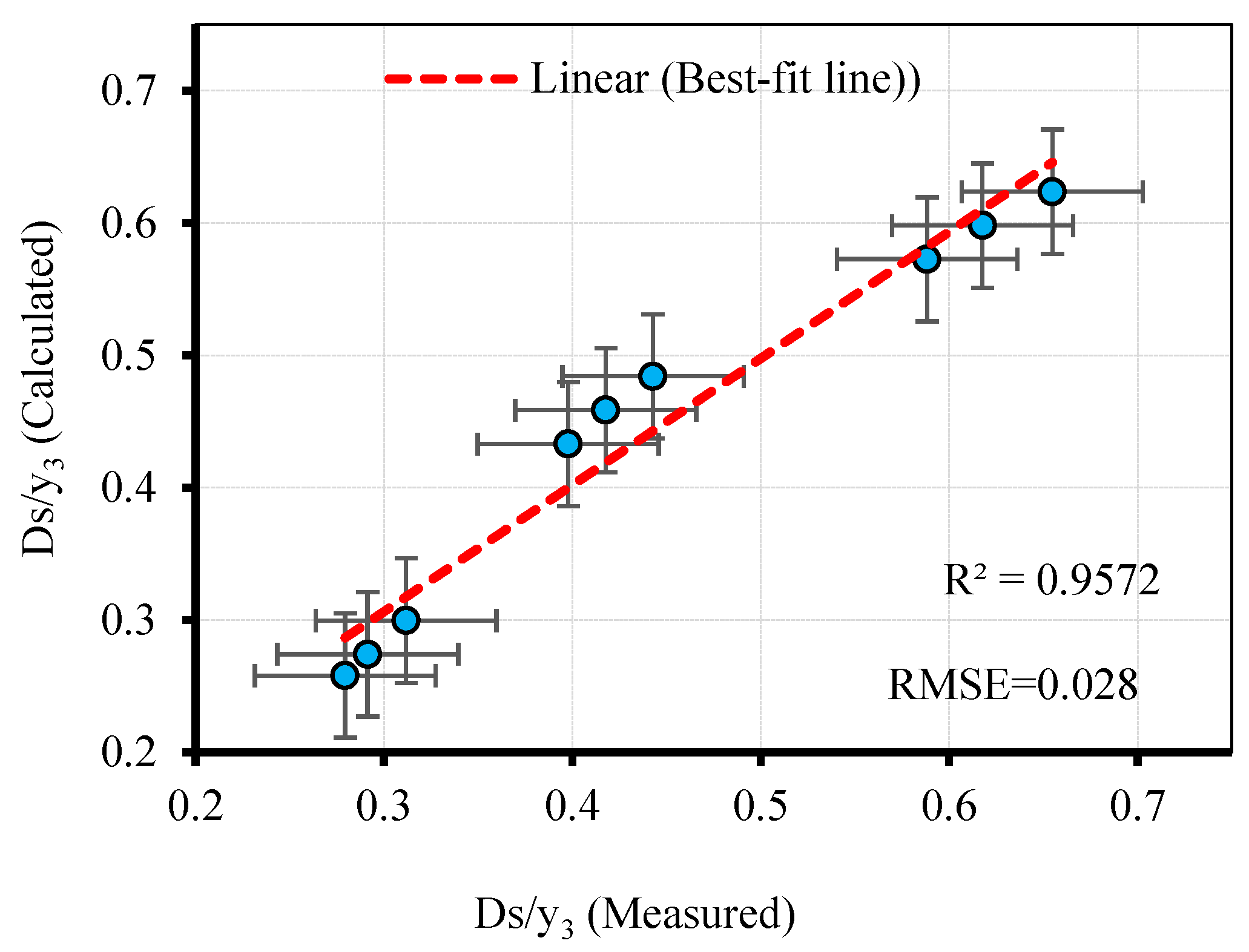
Figure 19 and
Figure 20, the predicted values of relative scour depth and scour length closely match the experimental measurements, with data points clustering around the best-fit line and low RMSE values. This strong agreement confirms the accuracy of the proposed equations in predicting both scour depth and length for the splayed wing wall configuration.
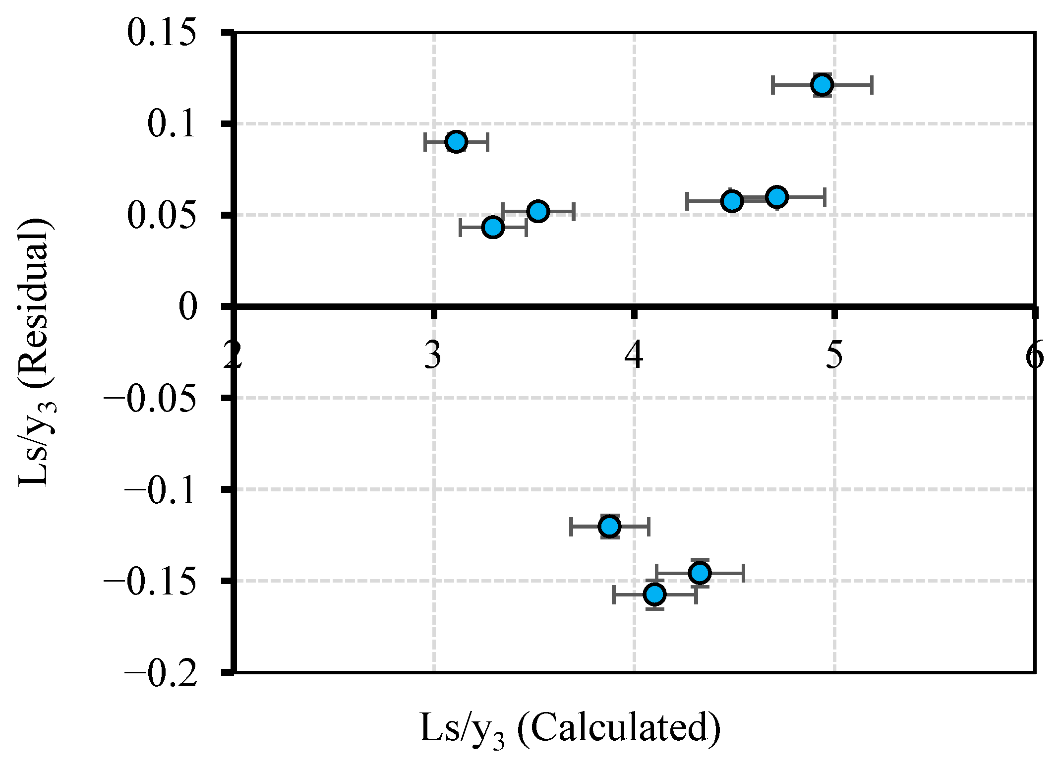
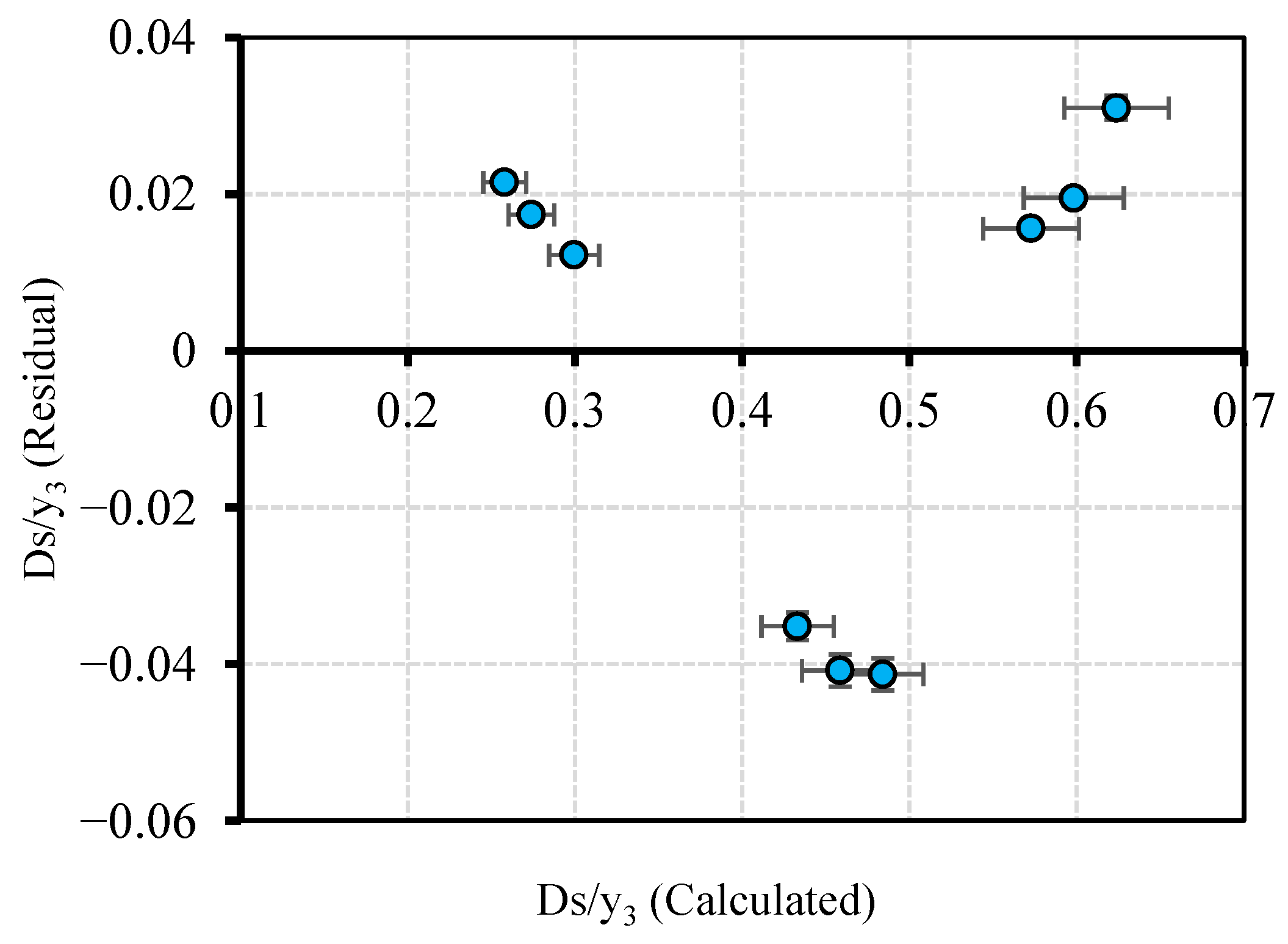
The residual plots presented in
Figure 21 and
Figure 22 illustrate the distribution of residuals for the normalized scour depth (Ds/y
3) and scour length (Ls/y
3), respectively, as functions of the predicted values. In both cases, the residuals are generally scattered around the zero line without exhibiting a strong systematic trend, suggesting that the proposed empirical models reasonably capture the underlying relationships.
For Ds/y
3 (
Figure 21), the residuals appear to be reasonably evenly distributed around zero, with no clear indication of non-constant variance within the investigated range, suggesting that the variance of errors remains approximately constant. Similarly, for Ls/y
3 (
Figure 22), although minor clustering of residuals is observed in specific regions, the overall distribution remains broadly random, indicating that any potential model bias is limited. These observations suggest that the main regression assumptions are reasonably satisfied and that the developed empirical relationships provide consistent predictions within the investigated range of parameters. In addition, the calculated VIF values for the independent variables (Fr
3 and Z) were within acceptable limits (VIF < 5), indicating that multicollinearity among the predictor variables is not significant.
4. Discussion
The obtained results support the initial working assumption that downstream scour behavior is governed by the combined interactive performance of both wing wall geometry and the canal inside slope, rather than by either parameter independently. The observed reductions in the scour hole depth and length represented with the drawn contour lines reflect the improved hydraulic response and modified flow structure at the entrance region, which agrees with previous studies.
Earlier investigations [
2,
4,
19,
21] indicated that reducing entrance angles and adopting streamlined geometries mitigate local scour by weakening flow separation and reducing turbulence intensity, which is consistent with the superior scour resistance observed in the present study for the splayed-type wing wall. Likewise, the increased scour severity associated with box-type or sharp-edged geometries agrees well with the findings of Melville et al. [
17], and Ghodsian et al. [
14], who attributed deeper scour to intensified flow contraction and increased turbulence levels near the structure entrance. While most previous studies primarily focused on geometric streamlining as the dominant control parameter, the present results extend this understanding by demonstrating that the canal inside slope plays a critical complementary role by regulating flow confinement, velocity distribution, and near-bed shear stress, thereby amplifying the effectiveness of wing wall geometry.
This agreement with previous studies can be attributed to the similarity in governing hydraulic mechanisms controlling local scour. In both the present and earlier investigations, the flow conditions are characterized by subcritical regimes and comparable ranges of Froude number, where flow separation, turbulence intensity, and near-bed shear stress dominate the scour process. Under such conditions, geometric modifications such as reducing entrance angles or adopting streamlined wing wall configurations consistently act to moderate flow contraction, redistribute velocity, and weaken the strength of horseshoe vortices. As a result, the underlying physical processes governing sediment entrainment and transport remain comparable, leading to consistent trends in scour behavior across different studies.
From an engineering perspective, the observed reduction in scour depth and scour length for streamlined wing wall configurations can be attributed to fundamental modifications in the flow at the entrance of the water structure. The splayed-type wing wall provides a gradual flow expansion that minimizes abrupt flow contraction, thereby reducing velocity gradients and suppressing large-scale flow separation zones. This smoother transition weakens the formation and intensity of horseshoe vortices at the wing wall toe, which are known to be the primary driving mechanism for sediment entrainment and scour. In addition, the reduced turbulence intensity near the bed leads to lower instantaneous bed shear stresses, limiting sediment mobilization and downstream erosion.
The influence of the canal inside slope further reinforces this behavior. A mild canal inside slope (Z = 1:1) promotes a more uniform velocity distribution and smoother momentum redistribution across the channel cross-section, reducing flow confinement and preventing excessive acceleration toward the channel bed. Conversely, steeper slopes increase flow concentration and enhance downward velocity components, which intensify bed shear stress and promote deeper scour. The combined effect of streamlined wing wall geometry and mild canal inside slope results in a more stable flow regime, improved energy dissipation, and reduced erosive capacity downstream. These hydraulic mechanisms provide a sound physical explanation for the superior scour resistance, enhanced structural safety, and improved hydraulic efficiency observed in the present study.
In a broader engineering and sustainability context, these findings underscore the importance of integrated geometric design in improving hydraulic performance, as reduced scour directly enhances structural safety, decreases maintenance frequency, and prolongs the service life of water structures within irrigation networks. Furthermore, the strong statistical significance and predictive accuracy of the developed empirical relationships support their applicability as practical design tools under subcritical flow conditions. Nevertheless, future research should focus on prototype-scale validation, investigate the effects of heterogeneous sediment gradation and bed armoring, and examine unsteady and flood-flow regimes to improve the generality and transferability of the proposed correlations.
5. Statistical Analysis and Significance
The statistical evaluation based on two-way ANOVA with replication confirms that both the canal inside slope and the upstream wing wall configuration significantly influence the working efficiency of the structure. For the relative energy loss parameter, the analysis produced a high F-statistic (F = 27.92) accompanied by a very low significance level (p-value < 0.001), along with a considerable effect size (η2 = 0.20). These results indicate that variations in entrance geometry account for a substantial proportion of the total observed variability. In addition, the afflux parameter exhibited a statistically meaningful response, with an F-value of 3.30 and a p-value of 0.038, demonstrating that afflux is sensitive to changes in geometric configuration. This indicates that modifications in entrance design are directly reflected in measurable variations in upstream water levels.
Further insight was obtained through post hoc Tukey’s HSD analysis, which identified the specific differences between tested configurations. The results show that a canal inside slope of Z = 1:1 leads to significantly lower energy loss compared to Z = 2:1, with a mean difference of 0.0132 (p-value < 0.001) and a large effect size (Cohen’s d = 0.89). Likewise, the splayed wing wall configuration significantly outperforms the box-type design, reducing energy loss by a mean difference of 0.0131 (p-value < 0.001), with a very large effect size (Cohen’s d = 1.31).
Overall, these statistical findings provide strong quantitative evidence supporting the experimental results. They confirm that entrance geometry plays a critical role in controlling working efficiency indicators. This strengthens confidence in the observed hydraulic trends and highlights the practical importance of optimized geometric configurations for improving working efficiency in water structure design.
6. Scope of Applicability and Limitations
By optimizing upstream wing wall layouts in conjunction with canal inside slope ratios, this study provides valuable insights into the hydraulic performance and associated scour behavior of water structures. Dimensionless empirical relationships were developed based on controlled laboratory experiments to predict key scour parameters, including scour depth and scour length, within specified boundary conditions. For the broken and splayed wing wall configurations, these conditions include an approach angle of 30°, canal inside slopes of 1:1, 3:2, and 2:1, a contraction ratio of 0.6 (r = b/B), and an approach-flow Froude number ranging from 0.12 to 0.18. The predicted scour characteristics are representative of similar bed-material conditions, as the experiments were conducted using uniform sand with a constant mean particle size.
Scour phenomena are inherently sensitive to scale effects, particularly with respect to sediment size and flow conditions. Although the experiments were conducted under controlled laboratory conditions to ensure consistency, complete similitude cannot be achieved in small-scale physical models. Therefore, the results should be interpreted in a relative sense, with greater emphasis on observed trends rather than absolute values. Accordingly, large-scale investigations with varied sediment sizes are recommended.
In addition, potential discrepancies in Reynolds’ number between laboratory and prototype scales may influence the flow structure and sediment transport mechanisms. Although the present experiments were conducted under fully turbulent conditions, scale-induced differences in viscous effects may affect the direct extrapolation of results to field applications.
Furthermore, the experiments were limited to uniform, non-cohesive sediment. In natural channels, the presence of cohesive soils or graded sediments may significantly alter scour behavior due to interparticle cohesion and variations in critical shear stress, potentially resulting in reduced scour depth or different equilibrium conditions.
Within these limitations, the developed equations provide a reliable basis for evaluating scour behavior downstream of water structures under comparable field conditions. However, the applicability of the results is restricted to steady-flow conditions and does not explicitly account for extreme hydraulic events, such as floods, highly turbulent flows, or rapidly varied flow conditions, which may significantly influence scour development.
In particular, unsteady flow conditions, such as flood events, may increase sediment transport rates and delay the attainment of equilibrium scour, thereby affecting both the magnitude and temporal evolution of scour depth.
In addition, field-related factors, including debris accumulation at the structure entrance, were not considered and may influence flow patterns and scour intensity. Within these limitations, the developed equations provide a reliable basis for evaluating scour behavior downstream of water structures under comparable field conditions. However, careful assessment is required to ensure consistency between actual site conditions and the experimental boundaries of this study before applying the proposed equations in practice.
For field applications, a validation protocol is recommended before applying the proposed empirical equations. This includes:
- ▪
Verifying that the hydraulic and geometric conditions (e.g., Froude number, contraction ratio, and channel slope) fall within or close to the investigated ranges.
- ▪
Comparing predicted scouring characteristics with available field measurements or observations, if accessible.
- ▪
Performing limited pilot-scale or site-specific tests, where feasible, to assess the applicability of the equations.
- ▪
Adopting conservative design values in cases where uncertainty exists or when conditions deviate from those evaluated in the present study.
7. Conclusions
The present work experimentally investigates the combined performance of both upstream wing wall geometry and canal inside slope on the hydraulic and scour behavior downstream of water structures. Through 435 laboratory experiments covering a wide range of flow conditions, wing wall configurations, and canal inside slopes, the following conclusions can be drawn:
- ▪
The interactive combined performance of different types of upstream wing walls with different degrees of canal inside slopes significantly affects the scour behavior of downstream water structures. Ignoring this interaction may lead to an underestimation of scouring risk and reduced structural safety.
- ▪
The splayed wing wall configuration exhibited the best hydraulic and scour performance among the tested cases when used with a canal inside slope of . The relative scour depth and length were reduced by approximately 22.74% and 23.61%, respectively, compared to the conventional box-type wing wall, which contributes to enhancing structural safety.
- ▪
Streamlined wing wall geometries (curved and splayed) improve flow transition, reduce turbulence and vortex intensity, and enhance scour resistance. In contrast, the box type induces flow contraction and higher turbulence, resulting in more severe scour. The splayed configuration shows the best performance, reducing energy loss and afflux by up to 84.12% and 30.01%, respectively, compared to the box type, when combined with a canal inside slope of 1:1.
- ▪
The canal inside slope was found to play a critical complementary role in scour mitigation. Mild slopes (Z = 1:1) provided more uniform velocity distribution and better energy dissipation, whereas steeper slopes intensified flow confinement and led to deeper and more extensive scour for all wing wall configurations.
- ▪
The Froude number had a dominant influence on scour development, as both relative scour depth (Ds/) and length (Ls/) increased with flow intensity. However, the performance of wing wall geometries remained consistent, underscoring the robustness of geometric effects on scour behavior.
- ▪
Eight empirical equations were developed and introduced for predicting the relative scour depth and length, with high statistical accuracy (R2 = 0.957–0.998). These relationships are suitable as practical design tools for preliminary scour assessment under subcritical flow conditions.
8. Recommendations
The following suggestions are put forward for researchers, engineers, and managers of water resources who are involved in the design and optimization of water structures in light of the findings of the current study:
Curved and splayed wing walls should be prioritized in new irrigation projects and in the rehabilitation of existing structures, as they consistently reduce downstream scour depth and extent compared to conventional configurations.
A 1:1 canal inside slope should be preferred in design, as it effectively minimizes scour depth and length while preserving structural stability. Where steeper slopes are required due to site conditions, appropriate mitigation measures such as canal lining, bed protection, or transitional slope treatments should be implemented at the upstream and downstream approaches.
During the early stages of design, the empirical relationships established in this study can be utilized as preliminary tools to estimate scour parameters (scour length and depth). Therefore, it is advised that they be included in engineering design manuals, technical recommendations, and professional training courses.
Further research is recommended to validate the laboratory findings under field-scale operating conditions, with particular emphasis on scour development, sediment transport processes, and debris accumulation effects under variable hydraulic conditions.





 ,
,