Review

Integrating Energy Storage Technologies with Renewable Energy Sources: A Pathway Toward Sustainable Power Grids

by
Farhan H. Malik
1,
Ghulam A. Hussain
2,*,
Yahia M. S. Alsmadi
1,
Zunaib M. Haider
3,
Wathiq Mansoor
2 and
Matti Lehtonen
4
1
Department of Electromechanical Engineering, Abu Dhabi Polytechnic, Abu Dhabi 13232, United Arab Emirates
2
College of Engineering and IT, University of Dubai, Dubai 14143, United Arab Emirates
3
Department of Electrical Engineering, The Islamia University of Bahawalpur, Bahawalpur 63100, Pakistan
4
School of Electrical Engineering, Aalto University, 02150 Espoo, Finland
*
Author to whom correspondence should be addressed.
Sustainability 2025, 17(9), 4097; https://doi.org/10.3390/su17094097
Submission received: 6 March 2025 / Revised: 20 April 2025 / Accepted: 29 April 2025 / Published: 1 May 2025

Abstract

:
The fact that electricity needs to be consumed at the same moment it is generated makes it very complicated to match supply and demand at all times. With the evolution of more and more intermittent renewable energy sources in the system, it has become more challenging to meet demand and supply in real time, hence the demand for energy storage systems to optimize energy costs and ease grid operations. The need for these systems arises because of the intermittency and uncontrollable production of wind, solar, and tidal energy sources. Therefore, a storage system that can store energy produced from renewable energy sources and then convert it into electrical energy when required is highly needed. Modern energy storage technologies play a pivotal role in the storage of energy produced through unconventional methods. This review paper discusses technical details and features of various types of energy storage systems and their capabilities of integration into the power grid. An analysis of various energy storage systems being utilized in the power grid is also presented. A review of a technology would be incomplete without the study of its ramifications for the environment. Therefore, the effect of various energy storage technologies on the environment is also a part of this comprehensive study.

1. Introduction

With declining fossil fuel resources, the pursuit continues for an answer to the inevitable question: “What will we do when fossil fuels run out”? This question is a multifaceted problem, and work on multiple fronts has been initiated to answer it. This includes but is not limited to improving the efficiency of existing generation methods for both conventional and unconventional sources. Studies have anticipated that the shift toward renewable resources has led to calls for better energy storage systems. Here, energy generation will be dealt with as a black box, and this paper will focus on energy storage systems and their integration into the power grid. Several energy storage systems have been identified and are listed in the form of a hierarchy chart, as shown in Figure 1.
Figure 1 provides an overview of the major categories of energy storage systems/technologies. The details of each system will be discussed in subsequent sections [1]. Although several storage technologies are listed in Figure 1, their utilization is not uniform. Most of the stored energy is in the form of pumped hydroelectric storage. Some of the major storage forms are listed in Table 1. The table also shows the percentage share of the various energy types based on the storage system utilized.
In the subsequent sections, energy storage technologies will be discussed in terms of their technical details and evolution or adoption in electric power systems. These details can be helpful in pointing out a favorable solution, but each scenario and application combined can be helpful in selecting any suitable storage type. Before discussing the details of each of the storage systems in separate sections, the following sub-sections provide the roles and impacts of these storage systems in the modern world.

1.1. Role of Energy Storage Systems in Power System Operations

The need for energy storage arises because neither consumer load profiles nor the generation of electricity remain constant or stable throughout the day. A typical load of a household also varies over the seasons due to heating/cooling requirements. Load profile are typically segregated into peak and off-peak hours based on the consumption of electricity. Energy consumption can fluctuate dramatically in a matter of seconds. In the absence of an energy storage system, the energy being produced at one moment might be wasted the next due to reduced demand. This surplus of energy ultimately leads to higher electricity costs and reduced grid efficiency.
Due to these abrupt variations that occur in a matter of seconds, it becomes necessary to have an energy storage system to store the excess energy being produced. This need for an energy storage system is made even more pressing by the inclusion of renewable energy production resources in the grid. This is because electricity production from renewables like PV systems and wind turbines is often at its maximum during off-peak hours and at a minimum—or nearly absent—during peak hours [6]. Energy storage helps to maintain load–generation balance, avoid brownouts and voltage fluctuations, and increase grid efficiency. Furthermore, energy storage systems make the generation process more economical and help reduce carbon emissions [7,8]. Another benefit of having an energy storage system is that it can be used to deliver electricity to neighboring grid zones with increased demand [9].
In the wake of global warming concerns, the primary focus has been on reducing carbon emissions, which are directly responsible for global warming. A large portion of these emissions are due to the generation of electricity from fossil fuels. As a result, several countries have pledged to reduce their emissions within self-imposed time frames by utilizing more green energy sources, including but not limited to PV, wind, and hydro. Therefore, it becomes necessary to pair these green energy sources with energy storage systems [10]. Energy storage systems are essential for applications that require uninterrupted power supply for smooth operations, such as the communications industry, the healthcare sector, and manufacturing plants [11].
Energy storage technologies (ESTs) play a vital role in integrating renewable energy sources into the modern power grid. Effective control systems, smart grid operations, and demand-side management are essential for optimizing the performance of ESTs. For instance, smart grids can dynamically balance supply and demand by utilizing real-time data and advanced optimization algorithms. Demand-side management can shift energy consumption to off-peak hours, reducing strain on the grid and enhancing the utilization of renewable energy sources.

1.2. Environmental Impact of Various Energy Storage Technologies

Energy storage technologies are often a double-edged sword and often provide benefits in exchange for some negative impacts. The environmental impacts of some of the commonly used energy storage technologies are shared below. However, energy storage technologies provide a big boost to the use and feasibility of renewable resources, and the environmental impact of these technologies is far lower than that of non-renewable resources. The precise negative impacts exerted on the environment are strictly technology-dependent and thus require category-dependent treatment in this section.

1.2.1. Pumped Storage Hydropower

This kind of renewable generation is often accompanied by large dams and reservoirs to provide uninterrupted power to the grid. The construction of these large structures is often responsible for the destruction of wildlife, flora and fauna, and many other civil structures in the area. A large amount of soil is often excavated, resulting in changes to local geology, which, in turn, lead to micro-seismic activities. Without proper planning and due diligence, hydropower plants can often disrupt the flow of rivers and streams and thus deprive adjoining areas of fresh water, which is needed for agriculture and daily use [12].

1.2.2. Compressed Air Energy Storage

CAES systems can be responsible for carbon emissions depending on how they operate. If grid power is utilized to drive the compressor during storage, emissions can be lower compared to burning fossil fuels for the same purpose. However, if the power output from these plants is supplemented with fossil fuels, it results in additional carbon emissions [12]. Furthermore, the underground caverns used for air storage come with their own risks and safety concerns.

1.2.3. Chemical Storage Technology

A number of different chemical storage technologies exist today, and each of these have their own pros and cons based on the type of chemicals used to store energy. For instance, lead-acid batteries use lead, which often leads to poisoning if ingested by humans and animals. Cadmium is another such material that poses harmful effects. In lithium-ion batteries, the constituent lithium is highly reactive with air. If the lithium is heated to a high enough temperature, it starts to burn and react with oxygen and nitrogen in the air. This often leads to catastrophic failure in poorly designed batteries. Lithium batteries have often been linked to many large-scale failures. On 30 July 2021, a fire broke out at the Victorian Big Battery storage facility due to leaking fluid in one of the Tesla Megapack modules [13,14]. Another incident occurred at a charging station in Beijing, where a fire erupted due to a sudden explosion, killing two firefighters and injuring one. The fire was eventually brought under control by 47 fire trucks and 235 firefighters [15,16].

1.2.4. Flywheels

Flywheel energy storage systems house many large, heavy metallic parts that revolve at speeds of over 10,000 RPM. These moving parts are housed in a vacuum chamber to achieve even greater speeds and conserve energy over longer durations. The main risk posed by these systems is the complete failure of the energy-storing flywheel itself, which, in the worst-case scenario, can result in metallic parts being ejected into the air, posing a threat to nearby people and structures [12]. Two incidents of flywheel failure occurred at a power plant in Massachusetts on 27 July and 13 October 2011. Following the investigation, it was discovered that the flywheels were constructed using faulty carbon fiber, which caused the flywheels to become unbalanced and grind against the walls of the vacuum chamber. This produced heat, and the temperature continued to rise despite being monitored by the system. The control system released water into the chamber to lower the temperature; however, this action backfired, as the water turned into steam, increasing the internal pressure and ultimately causing the chamber to explode [17].

1.2.5. Superconducting Magnetic Energy Storage (SMES)

When compared with other energy storage technologies mentioned in this section, SMES appears to be a more recent development that is undergoing frequent updates and improvements. From an environmental perspective, the mining of materials used in superconducting coils can be hazardous, depending on the materials involved. Furthermore, a carefully designed refrigeration system is required to cool the superconductors to extremely low temperatures. Since supermagnets are very powerful, the systems encasing them must be carefully designed to ensure proper shielding. However, this type of energy storage is generally a lot safer and more eco-friendly than other technologies [12].

1.2.6. Supercapacitors

Like supermagnets, supercapacitors do not pose any serious harmful threats to the environment. The chemicals used in supercapacitors are often harmless to the environment. However, improper handling or usage may lead to serious damage to nature—for instance, a short-circuited supercapacitor resulting in a fire.

2. Energy Storage Systems

2.1. Thermal Energy Storage

Thermal energy storage (TES) uses three main methods: conduction, convection, and radiation [18]. To convert this stored energy back into electricity, a thermoelectric generator or heat engine is required. As the name suggests, thermal energy storage deals with storing energy in the form of heat. This method of storing heat and using it later has improved the efficiency of power plants—especially natural gas plants—by up to 6%. In recent years, there has also been a lot of emphasis on the use of solar thermal systems in the USA and Spain. Solar energy can be focused or collected using parabolic troughs, heliostats, or dish reflectors [19]. It is estimated that by taking appropriate measures and developing policies, around 50% of the Europe’s heat energy requirements could be met by 2030 [20].
Thermal energy storage systems are categorized into three major types—sensible heat storage, latent heat storage, and reversible chemical reaction heat storage—as shown in Figure 2. Before we begin our categorical review of each TES type, let us first examine their parametric comparison.
Table 2 shows a brief comparison between different thermal storage technologies. When it comes to thermal energy storage technologies, reversible chemical reaction heat has the most potential to become a reliable source of energy storage. On the other hand, for short-term storage, sensible heat offers the cheapest products. For longer-duration and energy-dense storage, latent heat wins the vote.

2.1.1. Sensible Heat Storage

This method is one of the most widely used methods for storing energy in the form of heat. It basically exploits one property of materials—specific heat capacity [19]. This is defined as the amount of energy in Joules required to raise the temperature of 1 g of material by 1 °C. The higher this value, the more energy can be stored in the material. Table 3 gives the specific heat capacities of some materials.
By looking at Table 3, the specific heat capacity of water is approximately 4.1 KJ/(Kg °C), while for air, it is around 1 KJ/(Kg °C). This means that at any given temperature—say 50 °C—the amount of heat energy stored in water is four times greater than the amount of heat stored in air. Likewise, it would take four times more heat energy to raise the temperature of water by 1 °C as compared to air.
Sensible heat thermal energy storage (STES) can be categorized into two types based on the heat storage medium. If the storage medium is circulating within the system, it is classified as an active system, while in passive systems, the storage medium is static. Active systems are further categorized into active direct and active indirect systems. If the hot and cold storage materials are held in different tanks, it is called an active direct system. If they are stored in the same tanks, it is considered an active indirect system. Active direct systems do not require a heat exchanger, but their downside is the higher cost due to the need for separate tanks. On the other hand, active indirect systems have lower costs since both hot and cold materials are stored within a single tank. However, a major issue in these systems is maintaining a thermocline region between the two storage zones. For better stratification, silica or quartz is used to maintain the thermocline [19]. The storage materials can be solids, such as bricks or concrete, or liquids like molten salts. Sand also has great potential to store heat at high temperatures of up to 1000 °C, and its abundance makes it an effective and low-cost heat energy storage source [26].

2.1.2. Latent Heat Storage

Latent heat thermal energy storage (LTES) systems utilize the solid-liquid phase transition to store and release energy. Energy is absorbed by the material when it changes from solid to liquid and is released when the material returns to a solid state [27]. Storage materials are classified as organic, inorganic, and eutectic. Organic materials are chemically stable, easy to incorporate into building materials, and non-corrosive, but more expensive as compared to inorganic materials. Inorganic materials include metallic compounds and salt hydrates, and both have their own drawbacks. One issue is chemical decomposition in inorganic materials after undergoing multiple phase change cycles. Similarly, salt hydrates face cooling and low conductivity issues.
Another type of materials used for LTES is eutectic materials. Eutectic materials are formed by the mixture of two or more solid-phase components that melt into a liquid upon phase change. The temperature at which the solid-phase components melt is called the eutectic point temperature. The melting point of this mixture is lower than the melting points of individual compounds [28,29]. Latent thermal energy storage systems tend to store a greater amount of energy than sensible heat storage systems. This is because the heat released upon phase change in LTES can range from 100 to 340 KJ/Kg for a given temperature [30]. The materials used in LTES can be categorized into four possible phase transition groups: solid-solid, solid-liquid, solid-gas, and liquid-gas. Each group has its own pros and cons. Solid-solid transition materials are the best when it comes to containment and flexibility. For other groups, there can be a compromise between storage capacity and containment feasibility, such as in solid-gas phase change materials (PCMs).

2.1.3. Reversible Chemical Reaction Heat Storage

In reversible chemical reaction heat storage (CTES), heat is stored and released during endothermic/exothermic reactions. There are three types of CTES: heat of reaction systems, heat pump systems, and heat pipe systems. CTES systems can provide more efficient and dense storage compared to STES and LTES [19,31]. In chemical heat pumps, the processes of desorption and adsorption are used to exchange heat between a layer of gas/liquid and a solid. Some examples of such compounds are ammoniate-ammonia and metal hydride-hydrogen. The third methodology—chemical heat pipe systems—releases and absorbs energy during the dissociation of acidic and basic solutions like sodium hydroxide [32]. Reversible chemical storage systems are relatively new and developing methods. A lot of research is going into exploring these systems and discovering their full potential. A distinguishing feature of reversible chemical storage systems is that they offer long-term storage—something not provided by other thermal storage systems. The metal hydrates used to store energy are made with a combination of magnesium, nickel, iron or cobalt alloys with hydrogen [19]. Salt hydrates can also be used for energy storage, but they require certain conditions—including correct temperature and pressure control—for optimal performance. In some cases, the solid-gas combination of ice with carbon dioxide has also been used [33].

2.2. Mechanical Energy Storage

Mechanical energy storage (MES) stores energy as either potential or kinetic energy, and with appropriate mechanisms, this energy is transformed into electricity. The main forms of MES are pumped hydroelectric storage, compressed air, and flywheel systems, as shown in Figure 3. These are briefly explained in the following section.
Table 4 compares the three types of MES based on their parametric performance. When it comes to mechanical energy storage technologies, PHS is by far the best due to its scalability, almost zero self-discharge rate, long lifespan, and very low operation and maintenance costs. Although PHS has a lower energy density compared to other mechanical storage technologies, its ability to be scaled to very large projects—with production capacities often in the several MWs—and very long lifespan set it apart.

2.2.1. Pumped Hydroelectric Energy Storage (PHS)

Pumped hydroelectric energy storage is one the most exploited means of storage, mainly due to its feasibility and reliability as compared to other forms of energy storage. When it comes to durability, PHS reserves can be stored for days or even months depending on utilization. Some of the largest installed PHS facilities are located in Japan, with a combined capacity of 24.6 GW, and in the USA, which has a facility with a staggering capacity of 21.8 GW. There are also smaller-capacity installations around the world, such as the one in Spain with a capacity of 5.3 MW [3,35,36].
PHS systems can be categorized into two types based on their construction: one is known as the pure PHS system (shown in Figure 4), while the other is called a pump-back PHS system (shown in Figure 5) [36]. The main difference between the two is that in pure PHS systems, two large reservoirs with potential differences are used, with a turbine positioned below the upper reservoir. The water flows through penstocks from the upper reservoir to the turbine and then flows into the lower reservoir, or possibly a river or stream. The water from the lower reservoir is ultimately pumped back to the upper reservoir. This system is also referred to as a closed-loop system or an off-stream system. On the other hand, a pump-back PHS system utilizes both the flow of a natural source, such as a river or stream, and the water from the upper reservoir to generate electricity. Pump-back systems are more common due to their low cost, as they are compensated by a natural resource of water. They are also used for flood control and irrigation [36].
Like all systems, pumped hydroelectric storage systems come with certain pros and cons. Starting with pros, they have very low self-discharge rates, low operation and maintenance costs, a long lifespan, and high round-trip efficiencies [36,37]. In addition to these advantages, PHS systems are known to be highly reliable and are often used for the regulation of power and frequency stabilization [35,36].
The downsides of PHS systems are the long development time and higher initial capital investment. Due to these factors, PHS systems require a longer time to reach the breakeven point and sometimes make profitability uncertain [37,38]. The majority of the approved budget is spent on land acquisition, construction, and purchasing of electrical and mechanical machinery. Moreover, there are costs associated with the installation of transmission lines, reduction in environmental impact, and compliance with local regulations [38]. Two main factors that can restrict the construction of new PHS facilities are the financial burden and the unavailability of suitable locations [36,37]. Even if these two obstacles are overcome, resistance from residents of nearby areas is another major factor that can delay the start of the project. The main concerns of these people are often the result of a lack of awareness or incomplete knowledge of dams [38,39].
Recent progress has focused on different aspects of PHS systems. Optimization of vertical pipe intake-outlet structures has been achieved through the combined use of a response surface methodology (RSM), computational fluid dynamics (CFD), and a genetic algorithm [40]. Some researchers have focused on real-time energy management strategies for managing surplus renewable energy. One study has proposed methods for this purpose that use fuzzy logic and artificial neural networks [41].

2.2.2. Compressed Air Energy Storage (CAES) and Gravity Energy Storage (GES)

In this technology, energy is stored in the form of compressed air, which is later used to drive a turbine, as shown in Figure 6. The three main elements or processes involved are compression, storage, and expansion. Traditionally, these systems are designed to store energy when costs are at a minimum and release it when costs peak [42]. Several research efforts have focused on these main processes of CAES systems. Despite these efforts, CAES has still not achieved the same level of market penetration as PHS system, as shown in Table 1. Like PHS, CAES has a low self-discharge rate, low operational and maintenance costs, and a long service life [43]. However, it is highly unpredictable from an economic point of view [44]. One of the major factors that affects the feasibility of CAES systems is the storage unit. The storage can be specially built air tanks, dome-shaped salt caverns, mines, and empty natural gas wells. Each of these storage methods comes with its own cons. For instance, building special air tanks that can withstand pressure changes can be costly. Likewise, shaping a salt cave into a dome can take a couple of years [42].
When it comes to CAES, thermal energy is produced by rapid air compression and then stored. However, this thermal energy leaks into its surroundings, thus reducing the overall efficiency of the system. One way to overcome this issue is to utilize liquid pistons and water droplets to maintain isothermal conditions and improve heat transfer [45]. During the expansion phase, the pre-heated compressed air is allowed to mix with natural gas and then ignited while passing through a gas turbine. The expansion phase is also of deep interest to researchers [42]. When compared to the traditional gas turbine, the key difference between the two is that expansion and compression occur separately in CAES, which improves its efficiency. To further improve efficiency, additional heat energy is added by a recuperator to the pre-heated compressed air. This prevents cooling of the air and brittling of the turbine blades [46]. Round-trip efficiency can be increased to 90–95% by storing the compressed air energy in molten salts [42].
Improving the efficiency of CAES systems has been a constant topic of research. By introducing thermochemical recuperation into advanced CAES, direct heat transfer is achieved between gas and solid. This also helps maintain a stable turbine inlet temperature [47]. Another energy storage system is adiabatic compressed air energy storage (A-CAES), which is based on air compression and air storage in geologically concealed spaces. During operation, surplus electricity from intermittent renewable energy sources is used to compress air into a cavern at pressures of up to 100 bar at depths of hundreds of meters. The heat produced during the compression cycle is stored via thermal energy storage system, during which the air is compressed into underground caverns. In reverse, when the stored energy is needed, the compressed air is released to drive a turbine, while concurrently recovering heat from the thermal storage. This type of system can achieve efficiencies of around 70%, has a lifespan of more than 30 years, and can provide storage capacities up to 10GWh, as researched by the European Association for Storage of Energy (EASE) [48].
Gravity energy storage utilizes gravitational force to store energy by using existing mineshafts to support heavy masses for storing electrical energy. This system can have up to 50 years of lifespan and provide very fast response times, delivering high power at very low cost with almost zero losses [49]. As a use case, Finland is converting a disused mine into a gravity battery for energy storage [50].

2.2.3. Flywheel Energy Storage

Flywheels are designed to store rotational energy in large and heavy circular rotating masses. The main parts of a flywheel energy storage (FES) system are the flywheel, bearing, electric machine, power converter, and containment chamber. FES systems are best suited for applications that require short-term storage [51]. FES has many pros, such as a long system life with very little periodic maintenance, high power density, and fast response times [52].
There has been a lot of research on improving almost every subsystem of an FES system. Generally, high-speed flywheels operate in a vacuumed chamber to minimize frictional losses. However, this is not an economical solution due to expensive pumping machinery and poor heat dissipation. A mixture of gases, such as helium and air, has proved to be a better alternative due to low friction [53]. One primary concern consistently associated with FES systems is that of safety: Flywheels operating at high speeds are more prone to system failures, and thus a lot of research has been conducted to prevent these. Special composite and alloy materials have been produced to replace steel flywheels. A high-speed system can operate between 10,000 to 110,000 rpm [51,53]. In a report published by the US Energy Information Administration, it was noted that by the end of 2022, there were four operational FES power plants with a combined power generation capacity of 47 MW [54].

2.3. Electromagnetic Energy Storage

This category includes regular capacitors and inductors as well as the recently developed and continuously improving technologies of supercapacitors and superconductors. A brief overview of both the latter technologies is given in the subsequent section. Figure 7 features the two types of electromagnetic storage devices. First, let us compare them parametrically in Table 5. Currently, electromagnetic storage systems are marred by high self-discharge rates, low energy densities, and high capital costs. However, their long lifespans and life cycles warrant further research and innovation to develop these technologies and expand their use beyond a few applications.

2.3.1. Superconductors

Superconducting magnetic energy storage (SMES) systems have four major parts: a power converter, a containment chamber, a refrigeration unit, and a superconductor [55]. In superconductors, energy is stored in the magnetic field of an inductor. Applications of SMES include short-term power quality control in cases of grid failure. Superconductors are known to have a long life cycle, fast response times, and long lifespans. Two major downsides of this technology are the high discharge rate and capital costs [56].
There has also been research on using SMES as an augmentation of traditional lead-acid UPS systems. The superconductors in this scenario provide an initial short-term high-current discharge and thus reduce the load on the lead-acid batteries. This can be especially useful where outages generally last a few seconds [55]. Like other inductors, the windings of superconductors generally have a toroidal or solenoidal topology. Toroidal topologies are better at eliminating the stray magnetic fields that disrupt the normal flow of current [57]. However, this results in a more complex mechanical system.
In a typical SMES, these superconductors are cooled to a temperature below 0 K, depending on the material used to make the superconductor. For niobium–tin and niobium–titanium, temperatures of 24 K (−249 °C) are achieved. In SMES, the cost of cooling these superconductors to these extremely low temperatures is a major expense. Therefore, lot of research has focused on finding superconductors that can operate at higher temperatures, thus leading to the utilization of cheaper cooling agents like liquid nitrogen [58]. Some researchers have focused on reducing the amount of superconductor used in a typical SMES system to reduce the overall cost [59].

2.3.2. Electrostatic Energy Storage

Supercapacitors (SCs) have a potassium hydroxide electrolyte between their positive and negative plates and an ion exchange membrane between the two electrodes. Like in conventional capacitors, the capacitance of SCs depends on the distance between the two electrodes, the dielectric constant of the medium between the two plates, and the area of the plates. SCs generally have very high specific capacitance [60,61]. The main differences that set supercapacitors apart from conventional capacitors include the use of liquid electrolytes, porous electrodes made of carbon, and extremely short distances between these two—usually in the range of nanometers. These improvements enable supercapacitors to achieve capacitance in the order of thousands of farads [62]. Supercapacitors are further classified into two varieties based on the use of electrode types: symmetrical and asymmetrical SCs. In asymmetrical SCs, one of the electrodes is made up of a metal such, as nickel hydroxide, while the other is made up of carbon. In symmetrical SCs, both electrodes are made up of carbon. Due to the different electrode materials used in asymmetrical SCs, they have a higher energy density, making them suitable for large-scale applications [63,64].

2.4. Chemical Energy Storage

Chemical energy storage systems are the most explored and branched storage methods as compared to all the others described here. They also make up the most utilized form of energy storage devices. A hierarchical chart, shown in Figure 8, lists all the types of chemical energy storage technologies. The following subsections explain each of the types in detail.

2.4.1. Conventional Batteries

The main components of a battery are the cathode, the anode, an electrolyte, and a separator. The storage capacity, discharge rate, and life cycle of these batteries depend on the type of materials used in its production. Typically, batteries are made up of nickel-related compounds like nickel metal hydrides (NiMH), nickel cadmium (NiCd), and nickel iron (NiFe), or zinc-related compounds like zinc silver oxide (ZnAg) and zinc manganese dioxide (ZnMn). Other types of batteries include lithium-ion batteries (Li-ion) and lead-acid batteries [65]. The performance of these batteries depends on a variety of factors such as operating temperature, wattage, etc. If the batteries are non-rechargeable, they are called primary or single-use batteries, while rechargeable batteries are known as secondary batteries.
Zinc silver oxide batteries are perfect for both high- and low-current applications and have high durability along with a low environmental impact. However, the high cost of silver prevents these batteries from becoming the most popular among their counterparts. Hence, their use is mostly limited to low-current applications such as watches and hearing aids [66]. They have also been used in many popular applications, such as in the Apollo command module. To this day, zinc silver batteries find uses in submarines and torpedoes [67]. Recent developments have allowed for the manufacturing of rechargeable ZnAg batteries for high-current applications [68].
Another commonly used type of battery is alkaline zinc manganese dioxide (ZnMn) batteries. These are suitable for operation in low-temperature conditions and in applications with high and low current drain. When compared with zinc silver batteries, alkaline zinc manganese batteries have a higher discharge rate than ZnAg batteries and are produced at much cheaper rates [66]. However, their popularity and high usage has led to an increased amount of waste batteries; therefore, a better recovery and recycling strategy is needed [69]. A lot of work has been carried out to improve these batteries. The use of nanomaterials has resulted in better and more durable batteries with longer life cycles [70,71]. The addition of bismuth has also resulted in better cycle life [72]. Some studies have also focused on grid-level applications using flow-assisted alkaline batteries [73]. In addition, 3D printing techniques have been used to produce printable zinc manganese cells [74,75].
Another popular type of battery is the lead-acid battery. Its high power output, low maintenance schedule and costs, greater operating temperature range, and longer life cycle before performance degradation are some of its standout qualities. It is the go-to battery for starting, lighting, and ignition (SLI) applications as well as for uninterruptable power supplies (UPS). There are a few varieties of lead-acid batteries available on the market, including valve-regulated lead-acid (VRLA) batteries and sealed lead-acid batteries. VRLA batteries are designed to be maintenance-free, while SLA batteries are more suited for rougher conditions and are resistant to shock, vibration, chemicals, and heat [76]. However, lead-acid batteries are prone to sulfation in discharged states [66]. Research has been conducted into making thin-film variations of lead-acid batteries, which would lead to lower manufacturing costs. The use of titanium oxide has led to improved specific energy in bipolar batteries [77,78].

2.4.2. Lithium Ion Battery

Li-ion batteries are known for their long life cycles, low self-discharge rates and shelf life, and lower costs compared to other rechargeable batteries. Due to their high specific energy, energy densities, and good performance at low temperatures, they are mostly used in portable electronics and sometimes in space applications [66]. Despite all the pros mentioned in the preceding text, lithium-ion batteries are susceptible to thermal runaway, which can cause venting, explosion, or fire. It is imperative that a well-designed charging and monitoring schedule is implemented to prevent this. Lithium-ion batteries are difficult to recycle and are not suitable for large-scale applications [79,80].
When it comes to lithium-ion batteries, improvements have been made in a number of areas, with constant experiments and studies being conducted all over the world. The main areas for improvement have been better materials for anodes and cathode as well as better electrolytes. Anodes are generally made of graphite and are known for their low performance. Titanium niobium oxide (TNO) has been suggested as an alternative due to its high working voltage, safety, cycling stability, and pseudocapacitive behavior [81]. However, its conductivity is low, and the use of carbon nanotubes and graphene have been proposed to improve this limitation [82]. Other improvement methods that have been used include forming composites, doping, and size refinement [83,84,85,86,87].
Another material that has been has extensively researched for use in anodes is transition metal oxide [88,89]. Ni(OH)2 has been tested and researched as a viable option for anodes in lithium-ion batteries, but pure Ni(OH)2 exhibits only 30% capacity after 50 cycles [90,91]. Cu(OH)2 is another metal oxide that has been considered as a potential anode candidate in lithium-ion batteries [92,93]. Cu(OH)2 nanoflower arrays consisting of 50% Cu(OH)2 and 50% carbon nanotubes have shown a capacity retention of 95% after 50 cycles [90].

2.4.3. Nickel Batteries

Several different elements have been tested with nickel to form a suitable and cost-effective energy storage system. The most popular among these have been the nickel metal hydride (NiMH) batteries. They are commercially available as sealed and maintenance-free batteries. They are in direct competition with nickel cadmium (NiCd) batteries. When compared with NiCd batteries, NiMH offers higher energy densities, higher charge/discharge cycles before degradation, and a longer shelf life. However, when compared with lithium-ion batteries, NiMH tends to have a lower charge retention and specific power, higher costs, and a limited operating temperature range. These negative aspects are the driving force behind NiMH’s replacement by lithium-ion batteries [66]. There has been significant research on improving nickel metal hydride batteries. Some studies have focused on improving its low temperature performance and developing better electrodes [94]. The use of cobalt, zinc, and manganese in the electrodes has improved its resistance to corrosion as well as its operating temperature range [94,95].
Another nickel-based battery is the nickel-cadmium battery. In terms of their construction, they are like NiMH, but instead of a metal electrode, they use cadmium. NiCd batteries are suitable for high power output, low-temperature operations, and long life cycles [66]. Nickel cadmium batteries are best suited to applications with moderate discharge rates because they tend to exhibit a memory effect at low discharge rates. However, due to the toxic nature of cadmium, regulating authorities have favored NiMH over NiCd. Their use is now mostly restricted to aerospace applications.
Nickel iron (NiFe) batteries were once very popular due to their rugged construction and having the longest life cycle compared to contemporary batteries. They tend to have deep discharge capabilities and flexible charging schedules without any significant memory effect. However, their high cost of construction, high self-discharge rate, and internal resistance were the main factors for their phasing out after the advent of lead-acid batteries. Despite recent developments and improvements, their cost tends to be higher than that of lead-acid batteries but lower than nickel cadmium batteries [66]. Further research has focused on the use of potassium-, lithium-, and sulfide-additive porous polymer separators and metal fiber electrodes. Heating during charge/discharge cycles, high self-discharge rates, and hydrogen venting issues are still the main concerns relating to nickel iron batteries [96].
Another type of nickel battery is the nickel zinc (NiZn) battery. These have the best charge/discharge rates and low environmental impacts. Their commercial utilization is marred by their higher cost of construction and very short cycle life. Most of the recent research has focused on increasing the cycle life of nickel zinc batteries. The stability of the zinc electrode is the main cause of this shorter cycle life. Use of heavy metals such as mercury and hydroxides have improved the stability of zinc electrodes and hence the cycle life. Electrolytes with reduced alkalinity also tend to have a positive effect on life cycles [96]. The use of Bi2O3 coating on zinc anodes decreases the dissolution of discharge residues and protects the zinc anode from dendrites formation and shape changes [97]. The use of polyethylene glycol (PEG-300) as a protective layer in the electrolyte has also been demonstrated to prevent the self-corrosion of zinc electrodes [98].
In Table 6, common batteries, lithium-ion batteries, and nickel batteries are compared based on their parametric performance.
Lead-acid batteries are the main contender in many industrial and residential backup power systems due to their higher number of charging cycles and longer lifespan. These batteries can provide high power and withstand higher operating temperatures than their counterparts.
Table 6 and Table 7 compare the eight mostly widely used batteries around the world. Nickel batteries are often used at the industrial level. However, for residential consumers, lithium batteries have been the go-to in many electronic products for many years now due to increasing battery capacities and moderate power capabilities.

2.4.4. Molten Salt Batteries

In recent years, several non-traditional or emerging batteries have been made, tested, and improved. Since they are still in the early stages of their development, their applications are limited. One such technology uses molten salts, which simultaneously act as electrodes and electrolytes [102]. Sodium sulfur (NaS) and sodium nickel chloride (NaNiCl) are the two examples of such batteries. The most common application of sodium sulfur batteries is load leveling [103,104]. The operating temperatures of NaS batteries are within the range of 300–350 °C, which is much higher than traditional chemical batteries. They are cheaper than their counterparts and have seen a slower but steadier rise in commercial applications. Other applications include use in electric vehicles and grid voltage regulation [105,106], which could resolve the challenges behind electric vehicles’ [106] slow penetration into the market [107]. These batteries have also been proposed for a mission to Venus [108]. NaS batteries are known for their high power and energy density and are tolerant to external temperature variations. They have very low self-discharge rates and require little maintenance. They are also cheap to manufacture. However, thermal management is one of the main challenges associated with NaS batteries [66]. A heating mechanism is required to continuously maintain the operating temperature of the batteries. The heat produced during charging/discharging cycles is also used for this purpose. The efficiency of the batteries is reduced if the temperature falls below the operating range of 300–350 °C [104]. These batteries require not only a heating system but also a distribution system to evenly distribute the produced heat [109]. Well-designed insulation also reduces heating costs and helps retain heat for longer durations. Micro-porous materials and fiber boards are the most used insulators for this purpose. Another method involves the use of variable conductance insulators [110].
When it comes to NaS batteries, safety issues have always been a prime concern, and several tests have been proposed to evaluate them [111]. These batteries have also been linked to the infamous incident at the Tsukuba plant [112]. One of the methods for mitigating risks is to build a well-designed spill-free enclosure by lining the vessels with chromium and molybdenum. Lowering the operating temperature of batteries below 100 °C also reduces the corrosion of electrodes, which, in turn, prolongs the battery’s life. However, this step results in a slight amount of polysulfide reactions with electrodes [113].
NaNiCl batteries have primarily been designed for mobile applications and have thus undergone rigorous testing regimes including crash tests, fire exposure, water immersion, and short-circuiting [66]. NaNiCl batteries operate at a lower temperature (270 °C) compared to NaS batteries and thus have a lower negative environmental impact [113]. A battery named ZEBRA has been developed for electric vehicles [114]. This battery takes its name from the project under which it was developed, namely the Zeolite Battery Research Africa Project. These batteries are typically of 38 Ah and operate within 234–339 °C. NaS and NaNiCl batteries are some of the viable alternatives to traditional lithium-ion batteries because of their energy storage capacities and ruggedness.

2.4.5. Metal-Air Batteries

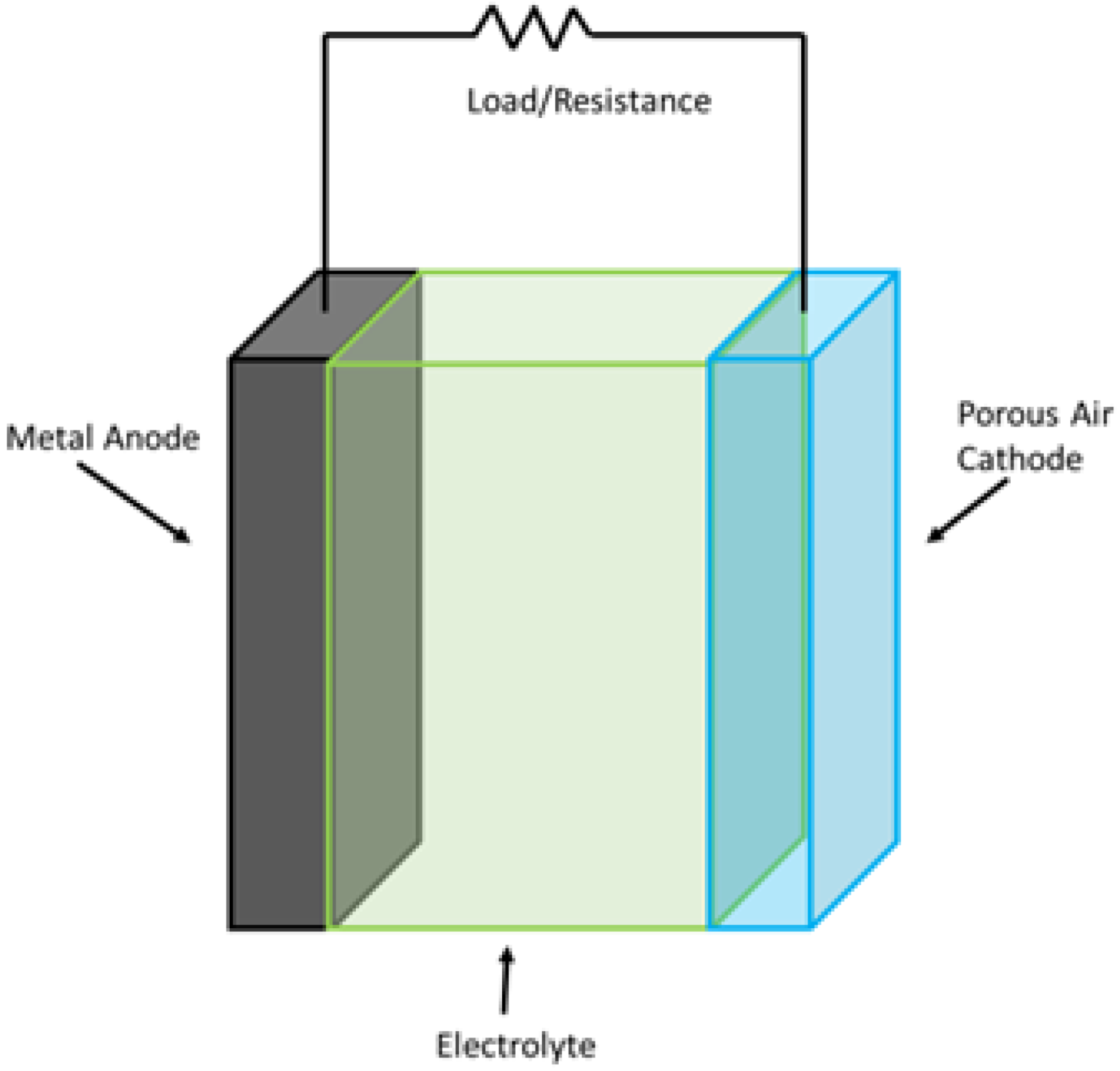
This class of batteries is composed of a metal electrode and an oxygen electrode. The metal electrode acts as an anode and is usually made up of lithium, zinc, iron, or aluminum. A specially designed separator separates an air- and carbon-based cathode, which acts as a catalyst to produce hydroxyl ions. A layout diagram of the battery is shown in Figure 9. When compared to other chemical-based energy storage systems, these batteries tend to offer higher energy densities. Moreover, lithium-air batteries offer energy densities that are comparable to those of fossil fuels.
One of the primary factors limiting the commercialization of these batteries is the hydrogen evolution reaction of the anode, due to which the anode’s life is severely shortened. Different methods have been proposed and tested to overcome this problem. One such solution involves the introduction of a bifunctional membrane between the metal anode and the electrolyte. This membrane performs two functions: allowing the entry of excess water and the transport of hydroxide ions. In the case of aluminum-air (Al-air) batteries, this membrane is made up of Al2O3@PAN. By the introduction of this membrane, a utilization rate of 61.2% of the aluminum anode can be achieved [115].
Another variation of metal-air batteries is the zinc air (Zn-air) battery. Its pros compared to other metal-air batteries include flat discharge curves at low current drains, lower costs compared to its counterparts, and a long shelf life when inactivated [66]. However, Zn-air batteries are sensitive to humidity and temperature variations. Zinc air batteries are suited for electric vehicle applications, and with the introduction of mechanical recharging by replacing the anode, they are capable of providing high energy densities [116,117]. They can be further improved by utilizing them with a mixture of nickel cadmium and manganese dioxide. Zn-air batteries are commonly utilized in electronics such as hearing aids.
Iron-air (Fe-air) batteries are yet another type of liquid metal-air battery. Fe-air batteries do not suffer from the corrosive effects of hydroxides as much as other metals like zinc or aluminum. This results in a longer service life and makes them suitable for large-scale applications. Despite these advantages, Fe-air batteries suffer from poor charging/discharging efficiencies. Some improvements have been observed using bismuth sulfide, carbonyl iron, and magnetite additions [118]. Recent improvements have increased the cycle life up to 5000 cycles and made the battery about 80% more efficient. Despite these improvements, these batteries currently seem to be a long way from commercialization. Two varieties of metal-air and molten salt batteries are compared in Table 8.
Molten salt batteries may not yet be the best option for many applications due to their short life cycles, high discharge rate, and higher costs. However, with more research and better products, they have the potential to replace many conventional batteries. On the other hand, metal-air batteries offer very low or negligible discharge rates along with long lifespans.

2.4.6. Fuel Cells

Fuel cells can be classified as both generation and storage devices. Fuel cell devices are made by stacking several single cells together to make high-voltage assemblies. Each cell is composed of three parts: electrodes, electrolyte, and the catalyst. The electrolyte is sandwiched between the two electrodes. Fuel can take the form of hydrogen, methanol, natural gas, ammonia, or other hydrocarbon gases. Other systems such as fuel and waste management and power conversion are also part of the complete fuel cell systems [66]. Although these cells use hydrocarbons for generation, the efficiencies of fuel cells are not limited by the Carnot cycle. They are also more environmentally friendly when compared to other similar generation and storage devices.
The major hurdles to the commercialization of fuel cells are related to its short lifespan and high costs. These cells have better energy densities compared to other chemical batteries, except for metal-air batteries. Impurities found in fuel cells can significantly reduce their performance. These impurities can produce corrosive gases which have a long-term negative impact on the environment and ecology [120].
In the subsequent sections, only four of the many existing fuel cell topologies are discussed: proton exchange membrane fuel cells (PEMFCs), molten carbonate fuel cells (MCFCs), direct methanol fuel cells (DMFCs), and solid oxide fuel cells (SOFCs).
PEMFCs work by directly converting hydrogen and oxygen for energy production. They require an operating temperature of about 70–85°C, and for this purpose, they are coupled with NiMH batteries to provide the optimal temperature. When compared to Li-ion batteries, PEMFCs have a better energy density but are expensive due to the higher costs of catalysts and membranes. As mentioned earlier, these cells are highly sensitive to impurities and thus have shorter lifespans. Cells come in different sizes, and each has its own pros and cons. Small cells can utilize replaceable storage cartridges. For this purpose, metal hydrides, chemical hydrides, compressed gas, and carbon hydrides have been considered. Hydrides require either high or very low cryogenic temperatures for hydrogen retention and release. However, there is a long way to go before these fuel cells can be commercialized.
DMFCs can operate at low temperatures by directly converting methanol into electricity and are perfect for small applications. However, their performance is marred by a slow startup time, low power density, and issues related to toxicity [121]. Catalysts can significantly increase the total cost of these fuel cells and thus remain a focus of research. Catalysts like rhodium, plutonium, and palladium can be expensive, while cheaper alternatives include zirconium alloys and nickel [122]. Modern research has focused on the biogenic synthesis of platinum from plant extracts to lower costs and improve catalytic activity [123]. Another study has focused on the use of TiCN coatings for use in DMFCs. The coatings were made at an average thickness of 15µm and have been recognized for their toughness and high electrical conductivity [124]. Nanocrystalline cellulose (NCC) membranes have also been studied for use in DMFCs [125]. Moreover, maintaining an optimal methanol concentration in DMFCs is of paramount importance, and the use of graphene aerogel (GA) on the membrane electrode assembly has been suggested to achieve this [126].
MCFCs are known for large grid-scale applications and generally have an operational temperature within the range of 600 °C. This allows hydrocarbon fuels to be converted into rich hydrogen gas. Of the three fuel cells mentioned so far, MCFCs are preferred for their high resistance to impurities and lower costs of production and operation. Special emphasis is given to electrode development, as it must have high porosity, mechanical resistance, and electrical conductivity, and low solubility [127]. The electrodes used in MCFCs are a constant area of research and improvement. The effect of pore size distribution inside the cathode has also been observed and studied, as it governs the electrolyte–gas interaction area [128]. The cathode is often made up of NiO and thus has high internal resistance and low power density in MCFCs. A three-layered cathode made up of porous silver tape cast on a standard NiO cathode with the addition of nickel foam as a support layer results in decreased resistance and high power density [129].
SOFCs are yet another type of fuel cell that operates at around 1000 °C with very high efficiency. In terms of their applications, these cells are used more often than MCFCs. The high temperature requirements of these cells result in additional heating costs and increased startup and shutdown times. Therefore, lowering the operational temperature of SOFCs has been an area of active research and experiments over the past few years. However, reducing the operational temperature results in a reduction in the conductivity of the cells. Therefore, newer electrolytes and membranes have been suggested for SOFCs [130]. Recent research has focused on the search for better electrolytes and electrodes. LiNi-oxide has been proposed for symmetrical electrolytes and electrodes in low-temperature SOFCs [131]. It has also been observed that the addition of reduced graphene oxide to the cathode functional layer improves the peak performance of cells by roughly 26%. This is due to the high electrical properties of graphene [132]. Ni-free anodes for SOFCs have also been suggested that can directly utilize anhydrous ethanol with the help of copper-based anodes [133]. Table 9 provides a comparison of their parametric performance values.
The numbers representing fuel cells may not be as impressive as those for other chemical energy storage systems, but with recent progress in industry, and thanks to initiatives taken by a few major industries, there are now hybrid vehicles on the road and many other applications are under development. However, fuel cell technology still requires a lot of innovation and research to make it a household name.

2.4.7. Flow Batteries

In flow batteries, active materials dissolved in the electrolyte traverse the cell to generate electricity. Flow batteries can be categorized into two types—redox flow batteries and metal/halide batteries—each having its own pros and cons. Redox flow batteries are made up of several bipolar cell stacks connected in parallel or series, a couple of tanks to hold the anolyte and catholyte, and a pumping system that is responsible for the flow of these active materials. These batteries are often used for grid-scale storage applications and their state of charge can be estimated by the color of the electrolyte. They are also suitable for applications involving the repeated deep discharge of batteries and are thus suitable for many applications [134]. The overall cost of this type of battery could be estimated by the cost of electrolyte in them [135].
In this section, three different types of flow batteries will be discussed: vanadium redox batteries (VRBs), zinc bromine batteries (ZBBs), and polysulphide bromine batteries (PBBs). VRBs are, without question, the best flow battery at the moment and also the most widely researched. They are known for their long service life along with constant deep discharge cycles and non-toxic materials. These batteries contain two variants of vanadium dissolved in the electrolyte [134]. Comparatively, they are currently more expensive than lead-acid batteries, but trends in the research have shown that they will soon be more economical.
The flexibility in the design of VRBs is astonishing. Large tanks for holding the electrolytes—one for the catholyte and one for the anolyte—can be built underground, which further prolongs the system’s lifespan by protecting it from the environment. These tanks can be made from various polymers. VRBs are also safe from the risk of short-circuiting [135]. Recent research on the development of VRBs has been multifaceted. Finding, testing, and developing new electrodes for flow batteries is often challenging and time-consuming. A novel technique for quickly scanning and testing carbon-based nanostructured materials as potential electrode candidates has been proposed [136]. The addition of chloride ions to the electrolytes can help increase the vanadium utilization ratio to 86.3% and the energy efficiency to 82.5%. These values are higher than those for electrolytes without additive chloride ions [137]. Other areas of research have focused on overcoming water and electrolyte imbalances and finding an optimal electrolyte flow rate control [138,139].
There have also been studies that have focused on finding cheaper alternatives to VRBs. One such variant is PBBs. Despite being cheap, they suffer from problems like corrosion, cross-contamination, and electrolyte imbalance. Another bromine variant, ZBB, is also available as a potential candidate for future promising technologies for large scale energy storage. They have high specific energy and efficiency, a long lifespan with repeated deep discharge cycles, and low manufacturing costs, thus remaining a topic of research and development. One of the challenges faced by zinc batteries is their low operating voltages—below 1.8 V. An alkaline–acid hybrid electrolyte has been suggested to improve voltages up to 3V [140]. One study has focused on carbonized Pomelo peel as an electrode substitute; the battery was observed for 100 cycles and no electrode degradation was observed [141]. Some researchers have focused on incorporating manganese into variants of flow batteries to achieve better performance [142,143]. Table 10 provides comparisons of their parametric values.
Flow batteries offer higher efficiencies compared to other chemistries, but their low energy and power density are among their biggest disadvantages. Flow batteries can be widely commercialized if they have higher energy and power densities along with corrosion-resistant materials. Another limitation is the requirement of larger electrolyte tanks to increase battery capacity.

3. Comparison of Energy Storage Technologies Based on Their Carbon Footprint and Operational and Maintenance Costs

Studies have frequently been conducted to estimate the carbon footprint, construction, and operation/maintenance costs of energy storage technologies. These studies are designed to take various aspects into account. In Table 11, the carbon emissions and operation and maintenance costs of some of the energy storage technologies are provided. Unless specified otherwise, these values are representative of cradle-to-grave studies performed over the lifetime of various projects.
Looking at the O&M costs in Table 11, it can be observed that the overall mechanical storage technologies have relatively low costs, whereas chemical storage technologies have higher O&M costs. Despite the high initial capital investments associated with mechanical storage, they outperform their counterparts due to longer lifespans and low O&M costs.

4. Integration of Energy Storage Systems with Renewable Energy Resources

Integrating energy storage technologies (ESTs) with renewable energy sources (RESs) is crucial for efficiency and grid stability, especially considering the variability involved in the production of electricity through these sources. A complete integration strategy generally involves advanced control systems, demand-side management (DSM) techniques, and smart grids. In this section, we will briefly discuss these aspects in light of recent advancements in these technologies. Having an advanced control system to manage the interaction between RESs and ESTs is necessary. In a recent study by Mahjoub et al. [154,155], a new energy management strategy for a micro-grid combining wind turbines, battery storage, and photovoltaic panels is introduced. In this strategy, the researchers utilized artificial intelligence algorithms to optimize power flow and predict energy production, thus ensuring a continuous power supply to loads under varying conditions. In order to achieve maximum power point tracking (MPPT) from each source, they used a double-input single-output DC-DC converter.
Demand-side management (DSM) is required to maintain a balance between supply and demand, especially as the penetration of RESs increases. A recent study by Alobaid and Abo-Khalil [156] has explored the integration of ESSs with DSM strategies in order to manage peak demand and enhance power quality. The authors highlighted the significance of tariffs and peak pricing in energy cost savings and promoting efficient energy use among consumers. It is essential to integrate ESTs into smart grids to facilitate efficient management of distributed energy resources (DERs). In a recent review by Worku [157], the role of ESTs in mitigating power fluctuations associated with RESs is highlighted. Emphasis is also placed on the utilization of appropriate storage technologies and power converters to optimize grid integration.
Despite all the recent advancements in various technologies associated with ESTs and RESs, some of key challenges still exist to some extent, though not as much as before. The selection of suitable ESTs and the coupling of effective control strategies with robust communication infrastructure are critical for successful integration. Issues such as voltage stability, power quality, and generation uncertainty still pose a considerable challenge [158,159,160].

5. Recent Advancements and Emerging Trends

PHS is one of the most widely deployed large-scale energy storage technologies. Recent research has focused on variable-speed pump-turbine systems that allow for dynamic load balancing and high renewable penetration. Developments in modular systems and underground PHS have helped reduce environmental impacts and topographical constraints. Studies have also focused on closed-loop PHS technologies [161].
CAES has evolved into a more efficient solution by adopting advanced adiabatic CAES. This process captures and reuses the heat generated through compression. This eventually leads to increased overall efficiency compared to traditional CAES systems. Recent studies have also focused on hybrid CAES technologies in which batteries are used to complement air compression [162,163].
FES technologies are particularly suitable for high-power, short-duration applications such as voltage stabilization and frequency regulation. State-of-the-art flywheels are being built using lightweight composite materials and are operated in a vacuum with magnetic bearings. This has led to very high life cycles. Recent research has also focused on stacked flywheel arrays for improved scalability [164,165,166].
A significant amount of research has focused on battery storage technologies over the past few years. One of the most researched technologies is the lithium-ion battery. Most of the research has focused on the aspects of energy density, longevity, and safety. It has been found that solid-state electrolytes offer a reduced risk of fire while enabling higher voltages. Studies on anode materials have led to the discovery that silicon and lithium-sulfur anodes offer the potential to double capacity. AI-based battery management systems are being developed for predictive health diagnostics [167,168].
Another type of widely used battery is the lead-acid battery. Recent developments have focused on carbon additives to the cathode to improve charge acceptance and reduce sulfation. Enhanced flooded batteries and absorbent glass mat technologies have helped extend their lifespan [169,170].
Among the other technologies, supercapacitors and superconductors are relatively new and developing. These technologies have seen a lot of progress over the last decade. Graphene and carbon nanotubes are being studied to enhance surface area and charge storage capabilities. Meanwhile, for superconducting magnetic energy storage, the research focus has been on high-temperature superconductors. This will lead to reduced cooling requirements and system complexity [171,172].
Among all the listed technologies, fuel cells are the latest development. Research is ongoing on for all the different types of fuel cells, including PEMFCs and SOFCs. Non-platinum catalysts and ceramic membranes are being developed to improve durability and costs [173,174,175].

6. Real-World Barriers to Implementation

Despite all the advancements in technology, certain challenges still exist. For instance, many of the ESTs discussed in this paper are associated with very high initial investments, such as building a PHS system, which involves costs associated with land procurement, terrain conversion, and the construction of reservoirs, feeding lines, and generators. Similarly, building a CAES or an FES also involves very high initial investment costs. Chemical energy storage systems are often associated with high operational costs. A study by Muhammad Adnan [176] emphasizes the fact that despite all the advancements in technology, the high costs associated with the production and mining of raw materials for lithium-ion batteries still continue to impede their broader adoption in our system.
Some of the ESSs discussed in this paper are relatively easy to scale, such as batteries, supercapacitors, and superconductors, etc. On the other hand, technologies such PHS, FES, and CAES require advanced planning and technical and economic assessments for scaling. A study by Lu et al. [177] discusses the importance of scalable solutions to improve the applicability of ESSs across different sectors. Furthermore, issues such as compatibility, cost-efficiency, and effectiveness need to be considered for both micro-scale devices and utility-scale grid applications [178].
When evaluated in terms of technical readiness, some of the mentioned ESTs face challenges, which are briefly discussed here. For example, PHS and CAES face significant scalability and environmental issues. Both of these technologies require certain geographical parameters [179,180]. For FES, the main concern is around its low energy density and relatively high large-scale deployment costs [166]. When it comes to lithium-ion batteries, they are one of the most market-ready technologies. However, despite all these advancements, concerns around safety during high temperatures and high charging/discharging rates remain considerable factors. Ongoing research is focusing on improving thermal stability, charging speed, and battery life [181].
Another type of challenge faced by these technologies is regulatory in nature. These challenges are often very localized and vary from location to location. For instance, PHS, CAES, and FES systems often face challenges from local people, as they are the most affected by the construction of these facilities. Concerns for nearby wildlife and flora remain a key challenge for these large-scale technologies [5]. When it comes to chemical energy storage technologies, additional regulatory issues often arise in relation to their safety, recycling, and mining for raw materials. Furthermore, in large-scale applications, concerns around fires are typical [182]. Table 12 shows a detailed comparative analysis of various technologies based on their energy density, power density, efficiency, lifespan, and capital cost.

7. Conclusions

The operation of power systems is very critical and is regarded as analogous to flying a jet aircraft, where a fraction of a second counts in maintaining stability. Voltage and frequency are directly influenced by the mismatch between electric power supply and demand, hence demands for standby energy storage systems that can compensate these fluctuations. This study has presented a comprehensive comparative analysis of various energy storage systems in the power system. By comparing key performance metrics such as efficiency, response time, capacity, and cost-effectiveness, this study provides valuable insights into the appropriateness of these technologies for various applications across the power system. The selection of technology depends on the given requirements of a power system. The pumped hydroelectric storage system is more effective for large-scale applications and feasible for long-duration energy storage, while batteries are well suited for short-duration applications and distributed energy storage. As sustainability becomes increasingly important, these considerations need to be incorporated into decision-making processes. As the energy transition continues, energy storage will play an essential role in achieving a more sustainable and robust energy future, and the perceptions outlined in this study can assist all stakeholders—including policymakers, system designers, and grid operators—in making informed decisions about the challenges and prospects presented by diverse energy storage systems.

8. Key Challenges and Future Research Directions

Despite all the advancements in technology, certain challenges still exist. For instance, many of the ESTs discussed in this paper are associated with very high initial investments, such as building a PHS system, which involves costs associated with land procurement, terrain conversion, and the construction of reservoirs, feeding lines, and generators. Similarly, building a CAES or an FES system also involves very high initial investment costs. Chemical energy storage systems are often associated with high operational costs. A study by Muhammad Adnan [176] emphasizes the fact that despite all the advancements in technology, the high costs associated with the production and mining of raw materials for lithium-ion batteries still continue to impede their broader adoption in our system. Some of the ESSs discussed in this paper are relatively easy to scale, such as batteries, supercapacitors, and superconductors, etc. On the other hand, technologies such PHS, FES, and CAES require advanced planning and technical and economic assessments for scaling. A study by Lu et al. [177] discusses the importance of scalable solutions to improve the applicability of ESSs across different sectors. Furthermore, issues such as compatibility, cost-efficiency, and effectiveness need to be considered for both micro-scale devices and utility-scale grid applications [178]. When evaluated in terms of technical readiness, some of the mentioned ESTs face challenges, which are briefly discussed in this study. For example, PHS and CAES face significant scalability and environmental issues. Both of these technologies require certain geographical parameters [179,180]. For FES, the main concern is around its low energy density and relatively high large-scale deployment costs [166]. When it comes to lithium-ion batteries, they are one of the most market-ready technologies. However, despite all these advancements, concerns around safety during high temperatures and high charging/discharging remain considerable factors. Ongoing research is focusing on improving thermal stability, charging speed, and battery life [181]. Another type of challenge faced by these technologies is regulatory in nature. These challenges are often very localized and vary from location to location. For instance, PHS, CAES, and FES systems often face challenges from local people, as they the most affected by the construction of these facilities. Concerns for nearby wildlife and flora remain a key challenge for these large-scale technologies [5]. When it comes to chemical energy storage technologies, additional regulatory issues often arise in relation to their safety, recycling, and mining for raw materials. Furthermore, in large-scale applications, concerns around fires are typical [182].
Future research could investigate one of the key challenges discussed below:
  • Advanced materials for next-generation batteries: In order to achieve the higher performance parameters associated with BES, we need to improve the existing materials as well as research better and more eco-friendly alternatives. Emerging technologies such as solid electrolytes, organic-based batteries, and sodium-ion batteries are gaining traction [183].
  • AI and machine learning for grid optimization and predictive maintenance: AI models can forecast renewable generation and optimize charge/discharge cycles and improve the lifespan of ESSs. It is expected that these tools will assist in real-time grid balancing and load forecasting [184].
  • Integration frameworks and standardization: Establishing universally accepted standards and policies for grid integration, safety, and data communication can facilitate the broader adoption of ESS technologies. This includes prosumer participation and real-time grid codes for distributed storage [185].

Funding

This research work was supported by a grant from the Ministry of Research, Innovation and Digitalization, UAE. Project number: PNRR-C9-18-760111/23.05.2023, Code CF 48/14.11.2022.

Conflicts of Interest

The authors declare no conflicts of interest.

Nomenclature

$ / k W h US Dollars per kilowatt-hour
C A E S  Compressed Air Energy Storage
C u ( O H ) 2 Copper Hydroxide
D M F C Direct Methanol Fuel Cell
F E S  Flywheel Energy Storage
k W / m 3 Kilowatt per meter cube
k W h / m 3  Kilowatt-hour per meter cube
L i i o n  Lithium Ion
L T E S Latent Heat Thermal Energy Storage
M C F C Molten Carbonate Fuel Cell
M W  Mega Watt
N a N i C l Sodium Nickel Chloride
N a S  Sodium Sulphur
N i ( O H ) 2 Nickel Hydroxide
N i C d Nickel Cadmium
N i F e Nickel Iron
N i M H Nickel Metal Hydride
N i Z n Nickel Zinc
P B B Polysulphide Bromine Battery
P E M F C Proton Exchange Membrane Fuel Cells
P H S  Pumped Hydroelectric Energy Storage
R C R H S Reversible Chemical Reaction Heat Storage
S C Supercapacitors
S L I Starting, Lighting and Ingnition
S M E S Superconducting Magnetic Energy Storage
S O F C Solid Oxide Fuel Cell
S T E S Sensible Heat Thermal Energy Storage
T N O Titanium Niobium Oxide
U P S Uninterrupted Power Supply
U R L A Valve Regulated Lead Acid
V R C Vanadium Redox Battery
Z B B Zinc Bromine Battery
Z n A g Zinc Silver
Z n M n Zinc Manganese

References

  1. Hameer, S.; van Niekerk, J.L. A review of large-scale electrical energy storage. Int. J. Energy Res. 2015, 39, 1179–1195. [Google Scholar] [CrossRef]
  2. Sabihuddin, S.; Kiprakis, A.E.; Mueller, M. A numerical and graphical review of energy storage technologies. Energies 2014, 8, 172–216. [Google Scholar] [CrossRef]
  3. Nikolaos, P.C.; Marios, F.; Dimitris, K. A review of pumped hydro storage systems. Energies 2023, 16, 4516. [Google Scholar] [CrossRef]
  4. Shaw, W. World’s Largest Compressed Air Energy Storage Project Comes Online in China. PV Magazine International. 2024. Available online: https://www.pv-magazine.com/2024/05/16/worlds-largest-compressed-air-energy-storage-project-comes-online-in-china/ (accessed on 1 April 2025).
  5. Murray, C. World’s Largest’ 30 MW Flywheel Energy Storage Project Connects to Grid in China. Energy-Storage News. 2024. Available online: https://www.energy-storage.news/worlds-largest-30mw-flywheel-energy-storage-project-connects-to-grid-in-china (accessed on 1 April 2025).
  6. Electricity Storage. United States Environmental Protection Agency. Available online: https://www.epa.gov/energy/electricity-storage (accessed on 28 May 2024).
  7. Office of Energy Efficiency and Renewable Energy. Renewable Energy. U.S. Department of Energy. Available online: https://www.energy.gov/eere/renewable-energy (accessed on 28 May 2024).
  8. Revankar, S.T. Chemical energy storage. In Storage and Hybridization of Nuclear Energy; Elsevier: Amsterdam, The Netherlands, 2019; pp. 177–227. [Google Scholar]
  9. Metz, D. Economic Evaluation of Energy Storage Systems and Their Impact on Electricity Markets in a Smart-Grid Context. Ph.D. Thesis, Universidade do Porto (Portugal), Porto, Portugal, 2016. [Google Scholar]
  10. Ralon, P.; Taylor, M.; Ilas, A.; Diaz-Bone, H.; Kairies, K. Electricity Storage and Renewables: Costs and Markets to 2030; International Renewable Energy Agency: Masdar City, Abu Dhabi, 2017; Volume 164. [Google Scholar]
  11. Fletcher, S. Bottled Lightning: Superbatteries, Electric Cars, and the New Lithium Economy; Hill and Wang: New York, NY, USA, 2011. [Google Scholar]
  12. Breeze, P. Power System Energy Storage Technologies; Academic Press: Cambridge, MA, USA, 2018. [Google Scholar]
  13. Colthorpe, A. Victorian Big Battery: Australia’s Biggest Battery Storage System at 450 MWh, Is Online. Energy-Storage News. 2021. Available online: https://www.energy-storage.news/victorian-big-batteryaustralias-biggest-battery-storage-system-at-450mwh-is-online (accessed on 28 May 2024).
  14. Colthorpe, A. Investigation Confirms Cause of Fire at Tesla’s Victorian Big Battery in Australia. Energy-Storage News. 2022. Available online: https://www.energy-storage.news/investigation-confirms-cause-of-fire-at-teslas-victorian-big-battery-in-australia (accessed on 28 May 2024).
  15. Behind the Explosion of the Beijing Lithium Battery Storage Power Station, What Is the Thinking of Us? Available online: https://www.iflowpower.com/a-news-behind-the-explosion-of-the-beijing-lithium-battery-storage-power-station-what-is-the-thinking-of-us (accessed on 28 May 2024).
  16. Zalosh, R.; Gandhi, P.; Barowy, A. Lithium-ion energy storage battery explosion incidents. J. Loss Prev. Process Ind. 2021, 72, 104560. [Google Scholar] [CrossRef]
  17. Buckowski, P. Flywheels Fail at Energy Project. The Hearst Corporation. 2011. Available online: https://www.timesunion.com/local/article/Flywheels-fail-at-energy-project-2227225.php (accessed on 28 May 2024).
  18. Dincer, I.; Rosen, M.A. Thermal Energy Storage: Systems and Applications; John Wiley & Sons: Hoboken, NJ, USA, 2011. [Google Scholar]
  19. Muthukumar, D.P. Thermal Energy Storage: Methods and Mate Thermal Energy Storage: Methods and Materials; Indian Institute of Technology: Guwahati, India, 2017. [Google Scholar]
  20. Kerskes, H.; Mette, B.; Bertsch, F.; Asenbeck, S.; Drück, H. Chemical energy storage using reversible solid/gas-reactions (CWS)–results of the research project. Energy Procedia 2012, 30, 294–304. [Google Scholar] [CrossRef]
  21. Schoenung, S.M. Characteristics of Energy Storage Technologies for Short-and Long-Duration Applications. Sandia Report SAND2001-0765. 2001. Available online: https://www.sandia.gov/ess-ssl/EESAT/2002_papers/00005.pdf (accessed on 28 May 2024).
  22. Kapila, S. Techno-Economic and Life Cycle Assessment of Large Energy Storage Systems. Master’s Thesis, University of Alberta, Edmonton, AB, Canada, 2018. [Google Scholar]
  23. Nadeem, F.; Hussain, S.S.; Tiwari, P.K.; Goswami, A.K.; Ustun, T.S. Comparative review of energy storage systems, their roles, and impacts on future power systems. IEEE Access 2018, 7, 4555–4585. [Google Scholar] [CrossRef]
  24. Greenwood, D.; Walker, S.; Wade, N.; Munoz-Vaca, S.; Crossland, A.; Patsios, C. Integration of high penetrations of intermittent renewable generation in future electricity networks using storage. In Future Energy; Elsevier: Amsterdam, The Netherlands, 2020; pp. 649–668. [Google Scholar]
  25. University of Texas. Heat Capacities for Some Select Substances. Available online: https://gchem.cm.utexas.edu/data/section2.php?target=heat-capacities.php (accessed on 28 May 2024).
  26. Polar Night Energy. Available online: https://polarnightenergy.com/ (accessed on 1 June 2024).
  27. Cabeza, L.; Martorell, I.; Miró, L.; Fernández, A.; Barreneche, C. Introduction to thermal energy storage (TES) systems. In Advances in Thermal Energy Storage Systems; Elsevier: Amsterdam, The Netherlands, 2015; pp. 1–28. [Google Scholar]
  28. Pena-Pereira, F.; de la Calle, I. Solvents and eutectic solvents. In Encyclopedia of Analytical Science; Elsevier: Amsterdam, The Netherlands, 2019. [Google Scholar]
  29. Smith, E.L.; Abbott, A.P.; Ryder, K.S. Deep eutectic solvents (DESs) and their applications. Chem. Rev. 2014, 114, 11060–11082. [Google Scholar] [CrossRef]
  30. Farid, M.M.; Khudhair, A.M.; Razack, S.A.K.; Al-Hallaj, S. A review on phase change energy storage: Materials and applications. Energy Convers. Manag. 2004, 45, 1597–1615. [Google Scholar] [CrossRef]
  31. Sharma, A.; Tyagi, V.V.; Chen, C.R.; Buddhi, D. Review on thermal energy storage with phase change materials and applications. Renew. Sustain. Energy Rev. 2009, 13, 318–345. [Google Scholar] [CrossRef]
  32. Nikolina, S. International Renewable Energy Agency (IRENA); EPRS: Brussels, Belgium, 2016. [Google Scholar]
  33. Fischer, M.; Bruzzano, S.; Egenolf-Jonkmanns, B.; Zeidler-Fandrich, B.; Wack, H.; Deerberg, G. Thermal storage by thermoreversible chemical reaction systems. Energy Procedia 2014, 48, 327–336. [Google Scholar] [CrossRef]
  34. Mostafa, M.H.; Aleem, S.H.A.; Ali, S.G.; Ali, Z.M.; Abdelaziz, A.Y. Techno-economic assessment of energy storage systems using annualized life cycle cost of storage (LCCOS) and levelized cost of energy (LCOE) metrics. J. Energy Storage 2020, 29, 101345. [Google Scholar] [CrossRef]
  35. Zisos, A.; Sakki, G.K.; Efstratiadis, A. Mixing renewable energy with pumped hydropower storage: Design optimization under uncertainty and other challenges. Sustainability 2023, 15, 13313. [Google Scholar] [CrossRef]
  36. Emrani, A.; Berrada, A. A comprehensive review on techno-economic assessment of hybrid energy storage systems integrated with renewable energy. J. Energy Storage 2024, 84, 111010. [Google Scholar] [CrossRef]
  37. Das Karmakar, S.; Chattopadhyay, H. Role of Pumped Hydro Storage to Mitigate Intermittency in Renewable Energy Systems. In Challenges and Opportunities of Distributed Renewable Power; Springer: Berlin/Heidelberg, Germany, 2024; pp. 305–321. [Google Scholar]
  38. Gyamfi, S.; Asuamah, E.Y.; Gyabaah, J.A. Techno-economic challenges of pumped hydro energy storage. In Pumped Hydro Energy Storage for Hybrid Systems; Elsevier: Amsterdam, The Netherlands, 2023; pp. 119–135. [Google Scholar]
  39. Elliot, J.; Brown, J.; Mlilo, N.; Bowtell, L. Global Trends in Community Energy Storage: A Comprehensive Analysis of the Current and Future Direction. Sustainability 2025, 17, 1975. [Google Scholar] [CrossRef]
  40. Zhang, H.; Gao, X.; Sun, B.; Qin, Z.; Zhu, H. Parameter analysis and performance optimization for the vertical pipe intake-outlet of a pumped hydro energy storage station. Renew. Energy 2020, 162, 1499–1518. [Google Scholar] [CrossRef]
  41. Mousavi, N.; Kothapalli, G.; Habibi, D.; Lachowicz, S.W.; Moghaddam, V. A real-time energy management strategy for pumped hydro storage systems in farmhouses. J. Energy Storage 2020, 32, 101928. [Google Scholar] [CrossRef]
  42. Halkhari, V. Study of Compressed Air Energy Storage with Grid and Photovoltaic Energy Generation; Arizona Research Institute for Solar Energy (AZRISE): Tucson, AZ, USA, 2010. [Google Scholar]
  43. Saadat, M.; Li, P.Y. Modeling and control of a novel compressed air energy storage system for offshore wind turbine. In Proceedings of the 2012 American Control Conference (ACC), Montreal, QC, Canada, 27–29 June 2012; IEEE: Piscataway, NJ, USA, 2012; pp. 3032–3037. [Google Scholar]
  44. Lund, H.; Salgi, G. The role of compressed air energy storage (CAES) in future sustainable energy systems. Energy Convers. Manag. 2009, 50, 1172–1179. [Google Scholar] [CrossRef]
  45. Van de Ven, J.D.; Li, P.Y. Liquid piston gas compression. Appl. Energy 2009, 86, 2183–2191. [Google Scholar] [CrossRef]
  46. Qin, C.; Loth, E. Liquid piston compression efficiency with droplet heat transfer. Appl. Energy 2014, 114, 539–550. [Google Scholar] [CrossRef]
  47. Lei, F.; Korba, D.; Huang, W.; Randhir, K.; Li, L.; AuYeung, N. Thermochemical heat recuperation for compressed air energy storage. Energy Convers. Manag. 2021, 250, 114889. [Google Scholar] [CrossRef]
  48. Fotopoulou, M.; Pediaditis, P.; Skopetou, N.; Rakopoulos, D.; Christopoulos, S.; Kartalidis, A. A Review of the Energy Storage Systems of Non-Interconnected European Islands. Sustainability 2024, 16, 1572. [Google Scholar] [CrossRef]
  49. Technology–Gravitricity. Available online: https://gravitricity.com/technology/ (accessed on 28 May 2024).
  50. This Disused Mine in Finland Is Being Turned into a Gravity Battery to Store Renewable Energy. Available online: https://www.euronews.com/green/2024/02/06/this-disused-mine-in-finland-is-being-turned-into-a-gravity-battery-to-store-renewable-ene (accessed on 28 May 2024).
  51. Peña-Alzola, R.; Sebastián, R.; Quesada, J.; Colmenar, A. Review of flywheel based energy storage systems. In Proceedings of the 2011 International Conference on Power Engineering, Energy and Electrical Drives, Malaga, Spain, 11–13 May 2011; IEEE: Piscataway, NJ, USA, 2011; pp. 1–6. [Google Scholar]
  52. Bolund, B.; Bernhoff, H.; Leijon, M. Flywheel energy and power storage systems. Renew. Sustain. Energy Rev. 2007, 11, 235–258. [Google Scholar] [CrossRef]
  53. Liu, H.; Jiang, J. Flywheel energy storage—An upswing technology for energy sustainability. Energy Build. 2007, 39, 599–604. [Google Scholar] [CrossRef]
  54. U.S. Energy Information Administration. Energy Storage for Electricity Generation. Available online: https://www.eia.gov/energyexplained/electricity/energy-storage-for-electricity-generation.php (accessed on 28 May 2024).
  55. Buckles, W.; Hassenzahl, W.V. Superconducting magnetic energy storage. IEEE Power Eng. Rev. 2000, 20, 16–20. [Google Scholar] [CrossRef]
  56. Ali, M.H.; Wu, B.; Dougal, R.A. An overview of SMES applications in power and energy systems. IEEE Trans. Sustain. Energy 2010, 1, 38–47. [Google Scholar] [CrossRef]
  57. What Is Stray Inductance? Available online: http://www.learningaboutelectronics.com/Articles/What-is-stray-inductance.php (accessed on 28 May 2024).
  58. Superconductivity: Present and Future Applications. Coalition for the Commercial Application of Superconductors, Superconductivity: Present and Future Applications. Available online: https://www.ccas-web.org/pdf/ccas_brochure_web.pdf (accessed on 28 May 2024).
  59. Dai, T.; Tang, Y.; Shi, J.; Jiao, F.; Wang, L. Design of a 10 MJ HTS superconducting magnetic energy storage magnet. IEEE Trans. Appl. Supercond. 2010, 20, 1356–1359. [Google Scholar]
  60. Zou, C.; Zhang, L.; Hu, X.; Wang, Z.; Wik, T.; Pecht, M. A review of fractional-order techniques applied to lithium-ion batteries, lead-acid batteries, and supercapacitors. J. Power Sources 2018, 390, 286–296. [Google Scholar] [CrossRef]
  61. Gao, X.; Dong, Y.; Li, S.; Zhou, J.; Wang, L.; Wang, B. MOFs and COFs for batteries and supercapacitors. Electrochem. Energy Rev. 2020, 3, 81–126. [Google Scholar] [CrossRef]
  62. Schindall, J. The charge of the ultracapacitors. IEEE Spectrum 2007, 44, 42–46. [Google Scholar] [CrossRef]
  63. Ganesh, V.; Pitchumani, S.; Lakshminarayanan, V. New symmetric and asymmetric supercapacitors based on high surface area porous nickel and activated carbon. J. Power Sources 2006, 158, 1523–1532. [Google Scholar] [CrossRef]
  64. Safdar, M.; Hussain, G.A.; Lehtonen, M. Costs of demand response from residential customers’ perspective. Energies 2019, 12, 1617. [Google Scholar] [CrossRef]
  65. Tarascon, J.M.; Armand, M. Issues and challenges facing rechargeable lithium batteries. Nature 2001, 414, 359–367. [Google Scholar] [CrossRef] [PubMed]
  66. Linden, D. Handbook of batteries. In Fuel and Energy Abstracts; McGraw-Hill Professional: New York, NY, USA, 1995; Volume 4, p. 265. [Google Scholar]
  67. DiCicco, M. NASA Research Helps Take Silver-Zinc Batteries from Idea to the Shelf. Available online: https://www.nasa.gov/directorates/spacetech/spinoff/feature/Silver-Zinc_Batteries (accessed on 28 May 2024).
  68. Dueber, R. Strategic overview of silver-zinc rechargeaable batteries. Battery Power Prod. Technol 2008, 12, 1–2. [Google Scholar]
  69. Olivetti, E.; Gregory, J.; Kirchain, R. Life Cycle Impacts of Alkaline Batteries with a Focus on End-of-Life; Massachusetts Institute of Technology: Cambridge, MA, USA, 2011; pp. 2–5. [Google Scholar]
  70. You-ju, H.; Yu-li, L.; Wei-shan, L. Manganese dioxide with high specific surface area for alkaline battery. Chem. Res. Chin. Univ. 2012, 28, 874–877. [Google Scholar]
  71. Ghaemi, M.; Amrollahi, R.; Ataherian, F.; Kassaee, M. New advances on bipolar rechargeable alkaline manganese dioxide–zinc batteries. J. Power Sources 2003, 117, 233–241. [Google Scholar] [CrossRef]
  72. Zhu, Z.; Kin Tam, T.; Sun, F.; You, C.; Percival Zhang, Y.H. A high-energy-density sugar biobattery based on a synthetic enzymatic pathway. Nat. Commun. 2014, 5, 1–8. [Google Scholar] [CrossRef]
  73. Ingale, N.D.; Gallaway, J.W.; Nyce, M.; Couzis, A.; Banerjee, S. Rechargeability and economic aspects of alkaline zinc–manganese dioxide cells for electrical storage and load leveling. J. Power Sources 2015, 276, 7–18. [Google Scholar] [CrossRef]
  74. Zou, Y.; Qiao, C.; Sun, J. Printable Energy Storage: Stay or Go? ACS Nano 2023, 17, 17624–17633. [Google Scholar] [CrossRef]
  75. Kincaid, B.; Poynter, K.B.H.T.; Ho, C. Printable Zinc Manganese Dioxide Batteries; University of California Berkeley: Berkeley, CA, USA, 2010. [Google Scholar]
  76. Sonic, P. Features of Sealed Lead Acid Batteries. Available online: https://www.power-sonic.com/blog/features-of-sealed-lead-acid-batteries/ (accessed on 28 May 2024).
  77. New Lead Acid Systems. Available online: https://batteryuniversity.com/article/bu-202-new-lead-acid-systems (accessed on 28 May 2024).
  78. Safdar, M.; Ahmad, M.; Hussain, A.; Lehtonen, M. Optimized residential load scheduling under user defined constraints in a real-time tariff paradigm. In Proceedings of the 2016 17th International Scientific Conference on Electric Power Engineering (EPE), Prague, Czech Republic, 16–18 May 2016; IEEE: Piscataway, NJ, USA, 2016; pp. 1–6. [Google Scholar]
  79. Xu, J.; Thomas, H.R.; Francis, R.W.; Lum, K.R.; Wang, J.; Liang, B. A review of processes and technologies for the recycling of lithium-ion secondary batteries. J. Power Sources 2008, 177, 512–527. [Google Scholar] [CrossRef]
  80. Wadia, C.; Albertus, P.; Srinivasan, V. Resource constraints on the battery energy storage potential for grid and transportation applications. J. Power Sources 2011, 196, 1593–1598. [Google Scholar] [CrossRef]
  81. Aghamohammadi, H.; Hassanzadeh, N.; Eslami-Farsani, R. A review study on titanium niobium oxide-based composite anodes for Li-ion batteries: Synthesis, structure, and performance. Ceram. Int. 2021, 47, 26598–26619. [Google Scholar] [CrossRef]
  82. Lin, C.; Wang, G.; Lin, S.; Li, J.; Lu, L. TiNb6O17: A new electrode material for lithium-ion batteries. Chem. Commun. 2015, 51, 8970–8973. [Google Scholar] [CrossRef] [PubMed]
  83. Liu, K.; Wang, J.a.; Yang, J.; Zhao, D.; Chen, P.; Man, J.; Yu, X.; Wen, Z.; Sun, J. Interstitial and substitutional V5+-doped TiNb2O7 microspheres: A novel doping way to achieve high-performance electrodes. Chem. Eng. J. 2021, 407, 127190. [Google Scholar] [CrossRef]
  84. Zhu, G.; Li, Q.; Zhao, Y.; Che, R. Nanoporous TiNb2O7/C composite microspheres with three-dimensional conductive network for long-cycle-life and high-rate-capability anode materials for lithium-ion batteries. ACS Appl. Mater. Interfaces 2017, 9, 41258–41264. [Google Scholar] [CrossRef]
  85. Lin, C.; Hu, L.; Cheng, C.; Sun, K.; Guo, X.; Shao, Q.; Li, J.; Wang, N.; Guo, Z. Nano-TiNb2O7/carbon nanotubes composite anode for enhanced lithium-ion storage. Electrochim. Acta 2018, 260, 65–72. [Google Scholar] [CrossRef]
  86. Yang, Y.; Yue, Y.; Wang, L.; Cheng, X.; Hu, Y.; Yang, Z.z.; Zhang, R.; Jin, B.; Sun, R. Facile synthesis of mesoporous TiNb2O7/C microspheres as long-life and high-power anodes for lithium-ion batteries. Int. J. Hydrogen Energy 2020, 45, 12583–12592. [Google Scholar] [CrossRef]
  87. Li, H.; Zhang, Y.; Tang, Y.; Zhao, F.; Zhao, B.; Hu, Y.; Murat, H.; Gao, S.; Liu, L. TiNb2O7 nanowires with high electrochemical performances as anodes for lithium ion batteries. Appl. Surf. Sci. 2019, 475, 942–946. [Google Scholar] [CrossRef]
  88. Yuan, C.; Wu, H.B.; Xie, Y.; Lou, X.W. Mixed transition-metal oxides: Design, synthesis, and energy-related applications. Angew. Chem. Int. Ed. 2014, 53, 1488–1504. [Google Scholar] [CrossRef]
  89. Jiang, H.; Sun, T.; Li, C.; Ma, J. Hierarchical porous nanostructures assembled from ultrathin MnO2 nanoflakes with enhanced supercapacitive performances. J. Mater. Chem. 2012, 22, 2751–2756. [Google Scholar] [CrossRef]
  90. Pramanik, A.; Maiti, S.; Mahanty, S. Metal hydroxides as a conversion electrode for lithium-ion batteries: A case study with a Cu(OH)2 nanoflower array. J. Mater. Chem. A 2014, 2, 18515–18522. [Google Scholar] [CrossRef]
  91. Li, B.; Cao, H.; Shao, J.; Zheng, H.; Lu, Y.; Yin, J.; Qu, M. Improved performances of β-Ni(OH)2@ reduced-graphene-oxide in Ni-MH and Li-ion batteries. Chem. Commun. 2011, 47, 3159–3161. [Google Scholar] [CrossRef] [PubMed]
  92. Gao, P.; Zhang, M.; Niu, Z.; Xiao, Q. A facile solution-chemistry method for Cu(OH)2 nanoribbon arrays with noticeable electrochemical hydrogen storage ability at room temperature. Chem. Commun. 2007, 5197–5199. [Google Scholar] [CrossRef]
  93. Zhang, W.; Wen, X.; Yang, S.; Berta, Y.; Wang, Z.L. Single-crystalline scroll-type nanotube arrays of copper hydroxide synthesized at room temperature. Adv. Mater. 2003, 15, 822–825. [Google Scholar] [CrossRef]
  94. Fetcenko, M.; Ovshinsky, S.; Reichman, B.; Young, K.; Fierro, C.; Koch, J.; Zallen, A.; Mays, W.; Ouchi, T. Recent advances in NiMH battery technology. J. Power Sources 2007, 165, 544–551. [Google Scholar] [CrossRef]
  95. Bäuerlein, P.; Antonius, C.; Löffler, J.; Kümpers, J. Progress in high-power nickel–metal hydride batteries. J. Power Sources 2008, 176, 547–554. [Google Scholar] [CrossRef]
  96. Tsais, P.J.; Chan, L. Nickel-based batteries: Materials and chemistry. In Electricity Transmission, Distribution and Storage Systems; Elsevier: Amsterdam, The Netherlands, 2013; pp. 309–397. [Google Scholar]
  97. Liu, X.; Wang, Q.; Liu, B.; Zhong, C.; Hu, W. Facile synthesis of uniformly coated ZnO@ Bi2O3 composites anode for long-cycle-life zinc–nickel battery. J. Energy Storage 2023, 58, 106350. [Google Scholar] [CrossRef]
  98. Yuan, H.; Luan, J.; Liu, J.; Zhao, N.; Zhong, C. Boosting ultra-long cycling and shelf life of nickel-zinc battery via guiding oriented zinc deposition and suppressing [Zn(OH)4]2-diffusion. Chem. Eng. J. 2023, 457, 141193. [Google Scholar] [CrossRef]
  99. Beaudin, M.; Zareipour, H.; Schellenberglabe, A.; Rosehart, W. Energy storage for mitigating the variability of renewable electricity sources: An updated review. Energy Sustain. Dev. 2010, 14, 302–314. [Google Scholar] [CrossRef]
  100. Rydh, C.J. Environmental assessment of vanadium redox and lead-acid batteries for stationary energy storage. J. Power Sources 1999, 80, 21–29. [Google Scholar] [CrossRef]
  101. Oliveira, L.; Messagie, M.; Mertens, J.; Laget, H.; Coosemans, T.; Van Mierlo, J. Environmental performance of electricity storage systems for grid applications, a life cycle approach. Energy Convers. Manag. 2015, 101, 326–335. [Google Scholar] [CrossRef]
  102. Bradwell, D.D.J. Liquid Metal Batteries: Ambipolar Electrolysis and Alkaline Earth Electroalloying Cells. Ph.D. Thesis, Massachusetts Institute of Technology, Cambridge, MA, USA, 2011. [Google Scholar]
  103. Hatta, T. Recent Applications of nas Battery System in the United States and in Japan. In Proceedings of the Electrical Energy Storage Applications and Technologies, San Diego, CA, USA, 17 October 2011. [Google Scholar]
  104. Kamibayashi, M.; Tanaka, K. Recent sodium sulfur battery applications. In Proceedings of the 2001 IEEE/PES Transmission and Distribution Conference and Exposition. Developing New Perspectives (Cat. No. 01CH37294), Atlanta, GA, USA, 2 November 2001; IEEE: Piscataway, NJ, USA, 2001; Volume 2, pp. 1169–1173. [Google Scholar]
  105. Walawalkar, R.; Apt, J.; Mancini, R. Economics of electric energy storage for energy arbitrage and regulation in New York. Energy Policy 2007, 35, 2558–2568. [Google Scholar] [CrossRef]
  106. Malik, F.H.; Lehtonen, M. Analysis of power network loading due to fast charging of Electric Vehicles on highways. In Proceedings of the 2016 Electric Power Quality and Supply Reliability (PQ), Tallinn, Estonia, 29–31 August 2016; IEEE: Piscataway, NJ, USA, 2016; pp. 101–106. [Google Scholar]
  107. Malik, F.H.; Haider, Z.M.; Ali, S.; Akram, S.; Khalid, M.; Dagher, S. What is Stopping EVs? A Different Approach to Analyze the Challenges. In Proceedings of the 2023 International Conference on Emerging Power Technologies (ICEPT), Topi, Pakistan, 6–7 May 2023; IEEE: Piscataway, NJ, USA, 2023; pp. 1–4. [Google Scholar]
  108. Landis, G.A.; Harrison, R. Batteries for Venus surface operation. J. Propuls. Power 2010, 26, 649–654. [Google Scholar] [CrossRef]
  109. Min, J.K.; Lee, C.H. Numerical study on the thermal management system of a molten sodium-sulfur battery module. J. Power Sources 2012, 210, 101–109. [Google Scholar] [CrossRef]
  110. Burch, S.D.; Parish, R.C.; Keyser, M.A. Thermal Management of Batteries Using a Variable-Conductance Insulation (VCI) Enclosure; Technical Report; National Renewable Energy Laboratory (NREL): Golden, CO, USA, 1995. [Google Scholar]
  111. Saruta, K. Long-term performance of sodium sulfur battery. In Proceedings of the 2016 IEEE 2nd Annual Southern Power Electronics Conference (SPEC), Auckland, New Zealand, 5–8 December 2016; IEEE: Piscataway, NJ, USA, 2016; pp. 1–5. [Google Scholar]
  112. Nikiforidis, G.; Van de Sanden, M.; Tsampas, M.N. High and intermediate temperature sodium–sulfur batteries for energy storage: Development, challenges and perspectives. RSC Adv. 2019, 9, 5649–5673. [Google Scholar] [CrossRef]
  113. Ellis, B.L.; Nazar, L.F. Sodium and sodium-ion energy storage batteries. Curr. Opin. Solid State Mater. Sci. 2012, 16, 168–177. [Google Scholar] [CrossRef]
  114. Veneri, O.; Capasso, C.; Patalano, S. Experimental study on the performance of a ZEBRA battery based propulsion system for urban commercial vehicles. Appl. Energy 2017, 185, 2005–2018. [Google Scholar] [CrossRef]
  115. Zuo, Y.; Yu, Y.; Shi, H.; Wang, J.; Zuo, C.; Dong, X. Inhibition of hydrogen evolution by a bifunctional membrane between anode and electrolyte of aluminum–air battery. Membranes 2022, 12, 407. [Google Scholar] [CrossRef]
  116. Arenas, L.; De León, C.P.; Walsh, F. Engineering aspects of the design, construction and performance of modular redox flow batteries for energy storage. J. Energy Storage 2017, 11, 119–153. [Google Scholar] [CrossRef]
  117. Shin, J.; Seo, J.K.; Yaylian, R.; Huang, A.; Meng, Y.S. A review on mechanistic understanding of MnO2 in aqueous electrolyte for electrical energy storage systems. Int. Mater. Rev. 2020, 65, 356–387. [Google Scholar] [CrossRef]
  118. Manohar, A.K.; Malkhandi, S.; Yang, B.; Yang, C.; Prakash, G.S.; Narayanan, S. A high-performance rechargeable iron electrode for large-scale battery-based energy storage. J. Electrochem. Soc. 2012, 159, A1209. [Google Scholar] [CrossRef]
  119. Burfeind, J. ELuStat: Iron-Air Battery as Stationary Energy Storage. Available online: https://www.umsicht.fraunhofer.de/en/projects/iron-air-battery.html (accessed on 28 May 2024).
  120. Dekel, D.R. Review of cell performance in anion exchange membrane fuel cells. J. Power Sources 2018, 375, 158–169. [Google Scholar] [CrossRef]
  121. Aricò, A.S.; Baglio, V.; Antonucci, V. Direct methanol fuel cells: History, status and perspectives. In Electrocatalysis of Direct Methanol Fuel Cells; Wiley: Hoboken, NJ, USA, 2009; pp. 1–78. [Google Scholar]
  122. Mansor, M.; Timmiati, S.N.; Lim, K.L.; Wong, W.Y.; Kamarudin, S.K.; Kamarudin, N.H.N. Recent progress of anode catalysts and their support materials for methanol electrooxidation reaction. Int. J. Hydrogen Energy 2019, 44, 14744–14769. [Google Scholar] [CrossRef]
  123. Ishak, N.; Kamarudin, S.; Timmiati, S.; Karim, N.; Basri, S. Biogenic platinum from agricultural wastes extract for improved methanol oxidation reaction in direct methanol fuel cell. J. Adv. Res. 2021, 28, 63–75. [Google Scholar] [CrossRef]
  124. Chen, Y.; Xu, J.; Jiang, S.; Xie, Z.H.; Munroe, P.; Kuai, S. Corrosion-resistant, electrically conductive TiCN coatings for direct methanol fuel cell. Surf. Coatings Technol. 2021, 422, 127562. [Google Scholar] [CrossRef]
  125. Muhmed, S.; Jaafar, J.; Daud, S.; Hanifah, M.F.R.; Purwanto, M.; Othman, M.; Rahman, M.; Ismail, A. Improvement in properties of nanocrystalline cellulose/poly(vinylidene fluoride) nanocomposite membrane for direct methanol fuel cell application. J. Environ. Chem. Eng. 2021, 9, 105577. [Google Scholar] [CrossRef]
  126. Guan, L.; Balakrishnan, P.; Liu, H.; Zhang, W.; Deng, Y.; Su, H.; Xing, L.; Penga, Ž.; Xu, Q. A tortuosity engineered dual-microporous layer electrode including graphene aerogel enabling largely improved direct methanol fuel cell performance with high-concentration fuel. Energies 2022, 15, 9388. [Google Scholar] [CrossRef]
  127. Cassir, M.; Ringuedé, A.; Lair, V. Molten carbonates from fuel cells to new energy devices. In Molten Salts Chemistry; Elsevier: Amsterdam, The Netherlands, 2013; pp. 355–371. [Google Scholar]
  128. Ibrahim, S.H.; Wejrzanowski, T.; Sobczak, P.; Cwieka, K.; Lysik, A.; Skibinski, J.; Oliver, G.J. Insight into cathode microstructure effect on the performance of molten carbonate fuel cell. J. Power Sources 2021, 491, 229562. [Google Scholar] [CrossRef]
  129. Ćwieka, K.; Lysik, A.; Wejrzanowski, T.; Norby, T.; Xing, W. Microstructure and electrochemical behavior of layered cathodes for molten carbonate fuel cell. J. Power Sources 2021, 500, 229949. [Google Scholar] [CrossRef]
  130. Zhao, Y.; Xia, C.; Jia, L.; Wang, Z.; Li, H.; Yu, J.; Li, Y. Recent progress on solid oxide fuel cell: Lowering temperature and utilizing non-hydrogen fuels. Int. J. Hydrogen Energy 2013, 38, 16498–16517. [Google Scholar] [CrossRef]
  131. Zheng, D.; Zhou, X.; He, Z.; Cai, H.; Xia, C.; Wang, X.; Dong, W.; Wang, H.; Wang, B. LiNi-oxide simultaneously as electrolyte and symmetrical electrode for low-temperature solid oxide fuel cell. Int. J. Hydrogen Energy 2022, 47, 27177–27186. [Google Scholar] [CrossRef]
  132. Timurkutluk, C.; Zan, R.; Timurkutluk, B.; Toruntay, F.; Onbilgin, S.; Hasret, O.; Altuntepe, A. Effect of reduced graphene oxide addition on cathode functional layer performance in solid oxide fuel cells. Int. J. Hydrogen Energy 2023, 48, 23127–23135. [Google Scholar] [CrossRef]
  133. Venâncio, S.A.; de Miranda, P.E.V. Ni-Free SOFC Anode Material with Thermal and Redox Stabilities for the Direct Utilization of Ethanol. Catalysts 2023, 13, 134. [Google Scholar] [CrossRef]
  134. Blanc, C.; Rufer, A. Understanding the vanadium redox flow batteries. Paths Sustain. Energy 2010, 18, 334–336. [Google Scholar]
  135. Skyllas-Kazacos, M.; Menictas, C.; Lim, T. Redox flow batteries for medium-to large-scale energy storage. In Electricity Transmission, Distribution and Storage Systems; Elsevier: Amsterdam, The Netherlands, 2013; pp. 398–441. [Google Scholar]
  136. Halada, Š.; Zlatník, J.; Mazúr, P.; Charvát, J.; Slouka, Z. Fast screening of carbon-based nanostructured materials as potential electrode materials for vanadium redox flow battery. Electrochim. Acta 2022, 430, 141043. [Google Scholar] [CrossRef]
  137. Zhang, Z.; Wei, L.; Wu, M.; Bai, B.; Zhao, T. Chloride ions as an electrolyte additive for high performance vanadium redox flow batteries. Appl. Energy 2021, 289, 116690. [Google Scholar] [CrossRef]
  138. Shin, J.; Jeong, B.; Chinannai, M.F.; Ju, H. Mitigation of water and electrolyte imbalance in all-vanadium redox flow batteries. Electrochim. Acta 2021, 390, 138858. [Google Scholar] [CrossRef]
  139. McCloy, R.; Li, Y.; Bao, J.; Skyllas-Kazacos, M. Electrolyte flow rate control for vanadium redox flow batteries using the linear parameter varying framework. J. Process Control 2022, 115, 36–47. [Google Scholar] [CrossRef]
  140. Yu, F.; Pang, L.; Wang, X.; Waclawik, E.R.; Wang, F.; Ostrikov, K.K.; Wang, H. Aqueous alkaline–acid hybrid electrolyte for zinc-bromine battery with 3V voltage window. Energy Storage Mater. 2019, 19, 56–61. [Google Scholar] [CrossRef]
  141. Wu, M.; Zhang, R.; Liu, K.; Sun, J.; Chan, K.Y.; Zhao, T. Mesoporous carbon derived from pomelo peel as a high-performance electrode material for zinc-bromine flow batteries. J. Power Sources 2019, 442, 227255. [Google Scholar] [CrossRef]
  142. Kim, M.; Lee, S.; Choi, J.; Park, J.; Park, J.W.; Park, M. Reversible metal ionic catalysts for high-voltage aqueous hybrid zinc-manganese redox flow batteries. Energy Storage Mater. 2023, 55, 698–707. [Google Scholar] [CrossRef]
  143. Sambandam, B.; Mathew, V.; Kim, S.; Lee, S.; Kim, S.; Hwang, J.Y.; Fan, H.J.; Kim, J. An analysis of the electrochemical mechanism of manganese oxides in aqueous zinc batteries. Chemistry 2022, 8, 924–946. [Google Scholar] [CrossRef]
  144. Abdin, Z.; Khalilpour, K.R. Single and polystorage technologies for renewable-based hybrid energy systems. In Polygeneration with Polystorage for Chemical and Energy Hubs; Elsevier: Amsterdam, The Netherlands, 2019; pp. 77–131. [Google Scholar]
  145. Denholm, P.; Kulcinski, G.L. Life cycle energy requirements and greenhouse gas emissions from large scale energy storage systems. Energy Convers. Manag. 2004, 45, 2153–2172. [Google Scholar] [CrossRef]
  146. Nguyen, X.P.; Hoang, A.T. The flywheel energy storage system: An effective solution to accumulate renewable energy. In Proceedings of the 2020 6th International Conference on Advanced Computing and Communication Systems (ICACCS), Coimbatore, India, 6–7 March 2020; IEEE: Piscataway, NJ, USA, 2020; pp. 1322–1328. [Google Scholar]
  147. Abdon, A.; Zhang, X.; Parra, D.; Patel, M.K.; Bauer, C.; Worlitschek, J. Techno-economic and environmental assessment of stationary electricity storage technologies for different time scales. Energy 2017, 139, 1173–1187. [Google Scholar] [CrossRef]
  148. Weber, S.; Peters, J.F.; Baumann, M.; Weil, M. Life cycle assessment of a vanadium redox flow battery. Environ. Sci. Technol. 2018, 52, 10864–10873. [Google Scholar] [CrossRef]
  149. McManus, M.C. Environmental consequences of the use of batteries in low carbon systems: The impact of battery production. Appl. Energy 2012, 93, 288–295. [Google Scholar] [CrossRef]
  150. Thaker, S.; Oni, A.O.; Gemechu, E.; Kumar, A. Evaluating energy and greenhouse gas emission footprints of thermal energy storage systems for concentrated solar power applications. J. Energy Storage 2019, 26, 100992. [Google Scholar] [CrossRef]
  151. Mahmud, M.P.; Huda, N.; Farjana, S.H.; Lang, C. Comparative life cycle environmental impact analysis of lithium-ion (LiIo) and nickel-metal hydride (NiMH) batteries. Batteries 2019, 5, 22. [Google Scholar] [CrossRef]
  152. Kilgore, G. Carbon Footprint of Lithium-Ion Battery Production (vs Gasoline, Lead-Acid). Available online: https://8billiontrees.com/carbon-offsets-credits/carbon-footprint-of-lithium-ion-battery-production/ (accessed on 28 May 2024).
  153. Amirante, R.; Cassone, E.; Distaso, E.; Tamburrano, P. Overview on recent developments in energy storage: Mechanical, electrochemical and hydrogen technologies. Energy Convers. Manag. 2017, 132, 372–387. [Google Scholar] [CrossRef]
  154. Mahjoub, S.; Chrifi-Alaoui, L.; Drid, S.; Derbel, N. Control and implementation of an energy management strategy for a PV–wind–battery microgrid based on an intelligent prediction algorithm of energy production. Energies 2023, 16, 1883. [Google Scholar] [CrossRef]
  155. Khan, M.R.; Haider, Z.M.; Malik, F.H.; Almasoudi, F.M.; Alatawi, K.S.S.; Bhutta, M.S. A comprehensive review of microgrid energy management strategies considering electric vehicles, energy storage systems, and AI techniques. Processes 2024, 12, 270. [Google Scholar] [CrossRef]
  156. Abo-Khalil, A.G.; Alobaid, M. A guide to the integration and utilization of energy storage systems with a focus on demand resource management and power quality enhancement. Sustainability 2023, 15, 14680. [Google Scholar] [CrossRef]
  157. Worku, M.Y. Recent advances in energy storage systems for renewable source grid integration: A comprehensive review. Sustainability 2022, 14, 5985. [Google Scholar] [CrossRef]
  158. Saleem, M.U.; Shakir, M.; Usman, M.R.; Bajwa, M.H.T.; Shabbir, N.; Shams Ghahfarokhi, P.; Daniel, K. Integrating smart energy management system with internet of things and cloud computing for efficient demand side management in smart grids. Energies 2023, 16, 4835. [Google Scholar] [CrossRef]
  159. Panda, S.; Mohanty, S.; Rout, P.K.; Sahu, B.K.; Parida, S.M.; Kotb, H.; Flah, A.; Tostado-Véliz, M.; Abdul Samad, B.; Shouran, M. An insight into the integration of distributed energy resources and energy storage systems with smart distribution networks using demand-side management. Appl. Sci. 2022, 12, 8914. [Google Scholar] [CrossRef]
  160. Khalid, M. Smart grids and renewable energy systems: Perspectives and grid integration challenges. Energy Strategy Rev. 2024, 51, 101299. [Google Scholar] [CrossRef]
  161. Odoi-Yorke, F.; Abbey, A.A.; Frimpong, T.A.; Asante, E.; Amewornu, E.M.; Davis, J.E.; Agyekum, E.B.; Atepor, L. A bird’s eye view of pumped hydro energy storage: A bibliometric analysis of global research trends and future directions. J. Energy Storage 2024, 103, 114339. [Google Scholar] [CrossRef]
  162. Jankowski, M.; Pałac, A.; Sornek, K.; Goryl, W.; Żołądek, M.; Homa, M.; Filipowicz, M. Status and development perspectives of the compressed air energy storage (CAES) technologies—A literature review. Energies 2024, 17, 2064. [Google Scholar] [CrossRef]
  163. Malik, F.H.; Khan, M.W.; Rahman, T.U.; Ehtisham, M.; Faheem, M.; Haider, Z.M.; Lehtonen, M. A comprehensive review on voltage stability in wind-integrated power systems. Energies 2024, 17, 644. [Google Scholar] [CrossRef]
  164. Wu, T.; Zhang, W. Review on Key Development of Magnetic Bearings. Machines 2025, 13, 113. [Google Scholar] [CrossRef]
  165. Dai, X.; Ma, X.; Hu, D.; Duan, J.; Chen, H. An overview of the R&D of flywheel energy storage technologies in China. Energies 2024, 17, 5531. [Google Scholar] [CrossRef]
  166. Xu, K.; Guo, Y.; Lei, G.; Zhu, J. A review of flywheel energy storage system technologies. Energies 2023, 16, 6462. [Google Scholar] [CrossRef]
  167. Jin, B.; Liao, L.; Shen, X.; Mei, Z.; Du, Q.; Liang, L.; Lei, B.; Du, J. Advancement in Research on Silicon/Carbon Composite Anode Materials for Lithium-Ion Batteries. Metals 2025, 15, 386. [Google Scholar] [CrossRef]
  168. Madani, S.S.; Shabeer, Y.; Allard, F.; Fowler, M.; Ziebert, C.; Wang, Z.; Panchal, S.; Chaoui, H.; Mekhilef, S.; Dou, S.X.; et al. A Comprehensive Review on Lithium-Ion Battery Lifetime Prediction and Aging Mechanism Analysis. Batteries 2025, 11, 127. [Google Scholar] [CrossRef]
  169. Dos Santos, A.G.; Vieira, M.R.S.; da Silva, F.J.; Bouchonneau, N. The effect of Ca and Bi addition on the mechanical strength, corrosion resistance, and Rechargeability of Pb1. 5Sn alloy for the positive grid of lead-acid batteries. Heliyon 2024, 10, e38536. [Google Scholar] [CrossRef]
  170. Cattelan, M.; Daniel, G.; Mazzucato, M.; Fabris, D.; Crivellaro, S.; Aliberti, R.; Parnigotto, M.; Cazzanti, S.; Durante, C. Effect of innovative carbon additives in the positive active mass of absorbent glass mat lead acid battery. Electrochim. Acta 2025, 512, 145537. [Google Scholar] [CrossRef]
  171. Oladele, I.; Adelani, S.; Taiwo, A.; Akinbamiyorin, I.; Olanrewaju, O.; Orisawayi, A. Polymer-based nanocomposites for supercapacitor applications: A review on principles, production and products. RSC Adv. 2025, 15, 7509–7534. [Google Scholar]
  172. Adetokun, B.B.; Oghorada, O.; Abubakar, S.J. Superconducting magnetic energy storage systems: Prospects and challenges for renewable energy applications. J. Energy Storage 2022, 55, 105663. [Google Scholar] [CrossRef]
  173. Singh, R.; Pratap, R.; Narayanan, J.A.; Thangamani, G.; Krishnan, V.V.; Arjunan, A.; Hughes, D. Advances in additive manufacturing of fuel cells: A review of technologies, materials, and challenges. Sustain. Mater. Technol. 2025. [Google Scholar] [CrossRef]
  174. Manzo, D.; Thai, R.; Le, H.T.; Venayagamoorthy, G.K. Fuel cell technology review: Types, economy, applications, and vehicle-to-grid scheme. Sustain. Energy Technol. Assess. 2025, 75, 104229. [Google Scholar] [CrossRef]
  175. Abedin, T.; Pasupuleti, J.; Paw, J.K.S.; Tak, Y.C.; Mahmud, M.; Abdullah, M.P.; Nur-E-Alam, M. Proton exchange membrane fuel cells in electric vehicles: Innovations, challenges, and pathways to sustainability. J. Power Sources 2025, 640, 236769. [Google Scholar] [CrossRef]
  176. Adnan, M. The future of energy storage: Advancements and roadmaps for lithium-ion batteries. Int. J. Mol. Sci. 2023, 24, 7457. [Google Scholar] [CrossRef] [PubMed]
  177. Lu, X.; Yang, X.; Wang, X.; Shi, Y.; Wang, J.; Yao, Y.; Gao, X.; Xie, H.; Chen, S. Small-Sample Battery Capacity Prediction Using a Multi-Feature Transfer Learning Framework. Batteries 2025, 11, 62. [Google Scholar] [CrossRef]
  178. Dong, Z.; Tao, Y.; Lai, S.; Wang, T.; Zhang, Z. Powering Future Advancements and Applications of Battery Energy Storage Systems Across Different Scales. Energy Storage Appl. 2025, 2, 1. [Google Scholar] [CrossRef]
  179. Mahfoud, R.J.; Alkayem, N.F.; Zhang, Y.; Zheng, Y.; Sun, Y.; Alhelou, H.H. Optimal operation of pumped hydro storage-based energy systems: A compendium of current challenges and future perspectives. Renew. Sustain. Energy Rev. 2023, 178, 113267. [Google Scholar] [CrossRef]
  180. Elalfy, D.A.; Gouda, E.; Kotb, M.F.; Bureš, V.; Sedhom, B.E. Comprehensive review of energy storage systems technologies, objectives, challenges, and future trends. Energy Strategy Rev. 2024, 54, 101482. [Google Scholar] [CrossRef]
  181. Sharma, H.; Sharma, S.; Mishra, P.K. A critical review of recent progress on lithium ion batteries: Challenges, applications, and future prospects. Microchem. J. 2025, 212, 113494. [Google Scholar] [CrossRef]
  182. Badawi, N.; Agrawal, N.; Luqman, M.; Ramesh, S.; Ramesh, K.; Khan, M.; Adil, S.F. Developments and challenges in batteries, and hydrogen as a future fuel, and storage and carrier devices. Int. J. Hydrogen Energy 2025, 105, 1242–1260. [Google Scholar] [CrossRef]
  183. Chou, J.H.; Wang, F.K.; Lo, S.C. A novel fine-tuning model based on transfer learning for future capacity prediction of lithium-ion batteries. Batteries 2023, 9, 325. [Google Scholar] [CrossRef]
  184. Lipu, M.H.; Miah, M.S.; Jamal, T.; Rahman, T.; Ansari, S.; Rahman, M.S.; Ashique, R.H.; Shihavuddin, A.; Shakib, M.N. Artificial intelligence approaches for advanced battery management system in electric vehicle applications: A statistical analysis towards future research opportunities. Vehicles 2023, 6, 22–70. [Google Scholar] [CrossRef]
  185. Agupugo, C.P.; Ajayi, A.O.; Nwanevu, C.; Oladipo, S.S. Policy and regulatory framework supporting renewable energy microgrids and energy storage systems. Eng. Sci. Technol. J. 2022, 5, 2589–2615. [Google Scholar] [CrossRef]
Figure 1. Types of energy storage based on their storing mechanism.
Sustainability 17 04097 g001
Figure 2. Hierarchy chart listing the three types of thermal energy storage technologies.
Sustainability 17 04097 g002
Figure 3. Types of mechanical energy storage systems.
Sustainability 17 04097 g003
Figure 4. Schematic of a pure PHS system.
Sustainability 17 04097 g004
Figure 5. Schematic of a pump-back PHS system with a natural water flow supplementing the storage.
Sustainability 17 04097 g005
Figure 6. Block diagram of compressed air energy storage.
Sustainability 17 04097 g006
Figure 7. Types of electromagnetic energy storage systems.
Sustainability 17 04097 g007
Figure 8. A tree diagram with different categories of chemical energy storage devices.
Sustainability 17 04097 g008
Figure 9. Schematic diagram of metal-air batteries showing the main components.
Sustainability 17 04097 g009
Table 1. Energy storage methods and their penetration in the world energy market [2,3,4,5].
Storage TypePower Capacity in MWPercentage ShareSource (Year)
Pumped Hydroelectric181,70098.378%IRENA (2023), DoE (2023)
Compressed Air16220.878%DoE (2023)
Flywheel9730.527%DOE (2023)
Sodium Sulphur3160.171%IEA (2023)
Lead Acid Battery350.019%IEA (2023)
Nickel Cadmium Battery270.015%IEA (2023)
Lithium Ion Battery200.011%IRENA (2023)
Flow Batteries30.002%IEA (2023)
Table 2. Comparative analysis of thermal energy storage technologies [2,21,22,23,24].
ParameterUnitReaction HeatLatent HeatSensible Heat
Energy DensityKWh/m3300.00100.00–370.0025.00–120.00
Power DensityKW/m3N.AN.AN.A
Efficiency%75.00–100.0075.00–90.0075.00–90.00
LifespanYearsUnknown20.00–40.0010.00–20.00
Lifetime CyclesCyclesN.AN.AN.A
Self-discharge rate%/dayUnknown0.5–1.000.50
Response timems–hminminmin
Energy Capital CostUS$/kWh10.90–137.003.00–88.730.04–50.00
Table 3. Specific heat values [25].
MaterialsSpecific Heat Capacity (J/g °C)
Air1.012
Aluminium0.89
Titanium0.523
Methanol2.14
Granite0.790
Graphite0.710
Lithium3.58
Water4.184
Water (steam, 100 °C)2.03
Table 4. Comparative analysis of PHS, CAES, and FES [2,21,22,23,34].
ParameterUnitPHSCAESFES
Energy DensityKWh/m30.50–1.330.40–20.000.25–424.00
Power DensityKW/m30.01–0.120.04–10.0040.00–2000.0
Efficiency%65.00–87.0057.00–89.0015.00–20.00
LifespanYears20.00–80.0020.00–40.0015–20.00
Lifetime CyclesCycles10,000–60,0008000–30,00010,000–100,000
Self-discharge rate%/day0024.00–100
Response timemin-hmins-mins
Energy Capital CostUS$/kWh1.00–291.001.00–140.00200.00–150,000.00
Table 5. Comparative analysis of electromagnetic energy storage systems [2,21,22,23].
ParameterUnitSupercapacitorSuperconductor
Energy DensityKWh/m31.00–35.000.20–13.80
Power DensityKW/m315.00–4500.00300.00–4000.00
Efficiency%65.00–99.0080.00–99.00
LifespanYears5.00–20.0020.00–30.00
Lifetime cyclesCycles10,000–1,000,00010,000–100,000
Self-discharge rate%/day0.46–40.001.00–15.00
Response timems–hmsms
Energy Capital CostUS$/kWh100.00–94,000.00500.00–1,080,000.00
Table 6. Comparative analysis of chemical energy storage technologies [2,21,22,23,99,100,101].
ParameterUnitZn-Ag OxideAlkalineLead AcideLithium Ion
Energy DensityKWh/m34.20–957.0360.00–400.0025.00–90.0094.00–500.00
Power DensityKW/m30.36–610.0012.35–101.7010.00–400.0056.80–800
Efficiency%20.00–100.0036.00–94.0063.00–90.0070.00–100.00
LifespanYears2.00–10.002.50–10.003.00–20.002.00–20.00
Lifetime CyclesCycles1–15001–200100–2000250–10,000
Self-discharge rate%/day0.01–0.250.008–0.0110.033–1.100.03–0.33
Response timems–hmsmsmsms
Energy Capital CostUS$/kWh3167–20,000100.00–100050.00–1100200.00–4000.00
Table 7. Comparative analysis of chemical energy storage technologies [2,21,22,23].
ParameterUnitNickel IronNickel CadmiumNickle ZincNickle Metal Hydride
Energy DensityKWh/m325.00–80.0015.00–150.0080.00–400.0038.90–300.00
Power DensityKW/m312.68–35.1837.66–141.05121.38–608.007.80–588.00
Efficiency%65.00–80.0059.00–90.0080.00–89.0050.00–80.00
LifespanYears8.00–1002.00–20.01.0–10.002.00–15.00
Lifetime cyclesCycles1000–8500300–10,000100–500300–3000
Self-discharge rate%/day0.36–1.430.07–0.710.60–1.070.30–4.00
Response Timems–hmsmsmsms
Energy Capital CostUS$/kWh444.27–1316330.0–3500.00250.0–660.0200.00–729.00
Table 8. Comparative analysis of chemical energy storage technologies [2,21,22,23,119].
ParameterUnitZn-AirFe-AirNaSNaNiCl
Energy DensityKWh/m322.00–1673.00100.00–1000.00150.00–345.00108.00–190.00
Power DensityKW/m310.00–208.002501.33–50.0054.20–300.00
Efficiency%30.00–50.0042.00–96.0065.00–92.0021.00–92.50
LifespanYears0.17–30.00 30.005.00–20.007.00–14.00
Lifetime cyclesCycles1.00–500.00100–50001000–45002000–3000
Self-discharge rate%/day0.005–0.01Negligible0.00–20.0011.89–26.25
Response Timems–hmsmsmsms
Energy Capital CostUS$/kWh10.00–950.010.00–150.00150.00–900.00100.00–345.00
Table 9. Comparative analysis of different fuel cell technologies [2].
ParameterUnitDirect MethanolPolymer Exchange MembraneMolten CarbonateSolid Oxide
Energy DensityKWh/m329.90–274.00112.00–770.0025.00–40.00172.00–462.00
Power DensityKW/m31.00–300.004.20–35.001.05–1.674.20–19.25
Efficiency%10.00–40.0022.00–85.0045.00–80.0050.00–65.00
LifespanYears0.01–0.560.22–10.001.40–10.000.28–10.00
Energy Capital CostUS$/kWh3065.00–3190.0070.00–13,000.00146.00–175.00180.00–333.00
Table 10. Comparative analysis of flow battery technologies [2,21,22,23,144].
ParameterUnitPolysulphide BromineVanadium RedoxZinc Bromine
Energy DensityKWh/m310.80–60.0010.00–33.005.17–70.00
Power DensityKW/m31.35–4.162.50–33.422.58–8.50
Efficiency%57.00–83.0060.00–88.0060.00–85.00
LifespanYears10.00–15.002.00–20.005.00–20.00
Lifetime cyclesCycles800–4000800–16,000800–5000
Response Timems–h<20 ms<1 ms<1 ms
Energy Capital CostUS$/kWh110.00–2000100.00–2000.00110.00–2000
Table 11. Comparing energy storage technologies based on their carbon footprint and operation and maintenance costs [22,34,101,145,146,147,148,149,150,151,152,153].
List of TechnologiesEmissions (g CO2/kWh)Operation and Maintenance Costs ($/kWh)
PHS23.5–6502–10
FES6785 kg CO2 *5–6
CAES161–2722–5
Lithium-ion259–3352–123
Lead-acid104–7703–26
Sodium Sulfur37.90–6402–54
Vanadium Redox52–2794–51
Alkaline Batteries107 g CO2 eq per batteryNA
Nickle Cadmium0.04–0.05 14–26
Nickle Metal Hydride6.06 k 2NA
Sodium Nickel Chloride32.50–607NA
Thermal Storages7–28 3, 9–34 4, 9–27 5NA
Polysulphide32.6 6NA
SupercaapcitorNA1–6
Zinc BromineNA3–7
* Amount of carbon dioxide produced over a 15-year lifetime during the material production required for FES. 1—Cradle-to-gate estimation involving the production of batteries only. 2—Per kg of batteries produced. 3—For two-tank sensible heat storage setup. 4—For latent heat storage setup. 5—For thermochemical storage. 6—Estimations for cradle-to-gate stages as well as operation and decommissioning.
Table 12. Comparative analysis of all energy storage technologies.
ParameterEnergy DensityPower DensityEfficiencyLifespanCapital Cost
PHSLowLowMediumHighLow
CAESLowMediumMediumHighMedium
FESLowHighHighHighHigh
Reaction HeatMediumLowMediumMediumMedium
Latent HeatMediumLowMediumMediumMedium
SupercapacitorLowVery HighHighVery HighHigh
SuperconductorVery HighVery HighVery HighVery HighVery High
Lead AcidLowMediumLowLowLow
Lithium ionHighHighHighMedium–HighMedium
Nickle IronMediumMediumMediumVery HighHigh
Nickle ZincMediumHighMediumMediumMedium
Nickle CadmiumMediumHighMediumHighMedium
Zn-AirHighMediumMediumMediumMedium
Fe-AirHighMediumMediumMediumMedium
Direct MethanolMediumMediumMediumMediumHigh
Vanadium RedoxMediumMediumHighHighHigh
Zinc BromineMediumMediumMediumMediumMedium
Disclaimer/Publisher’s Note: The statements, opinions and data contained in all publications are solely those of the individual author(s) and contributor(s) and not of MDPI and/or the editor(s). MDPI and/or the editor(s) disclaim responsibility for any injury to people or property resulting from any ideas, methods, instructions or products referred to in the content.

