


Constitutive Behaviour of Recycled Rubber-Involved Mixtures for Transportation Infrastructure


Abstract
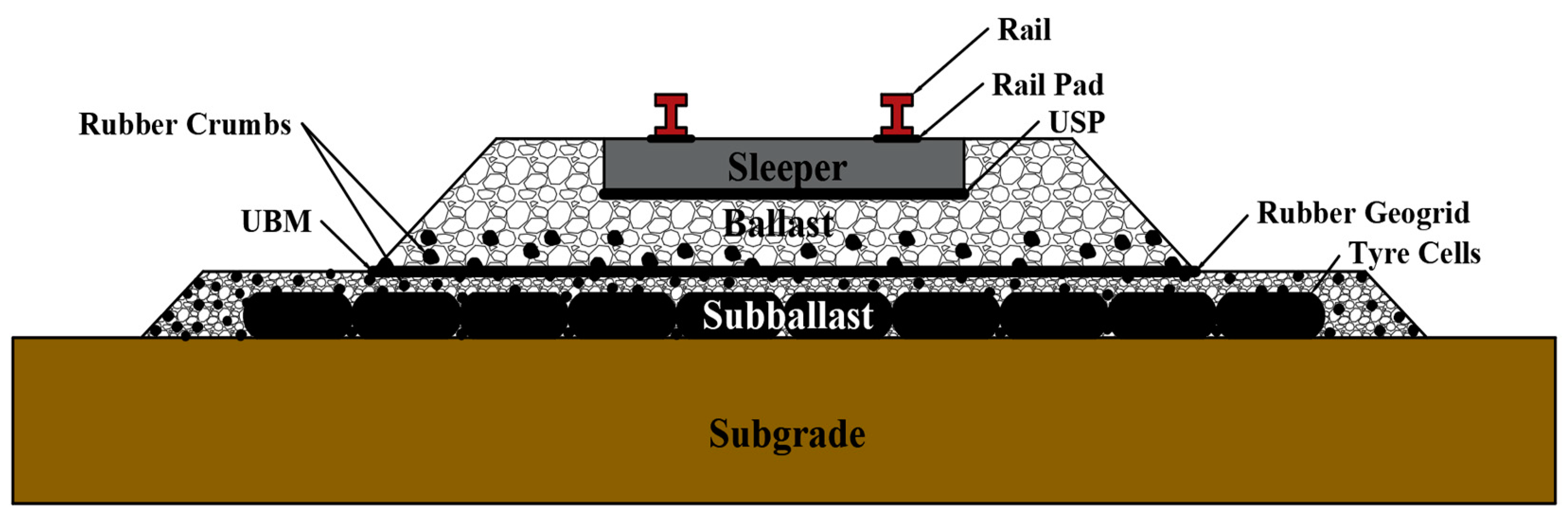
1. Introduction
2. Stress–Strain Characteristics of Rubber-Mixed Materials
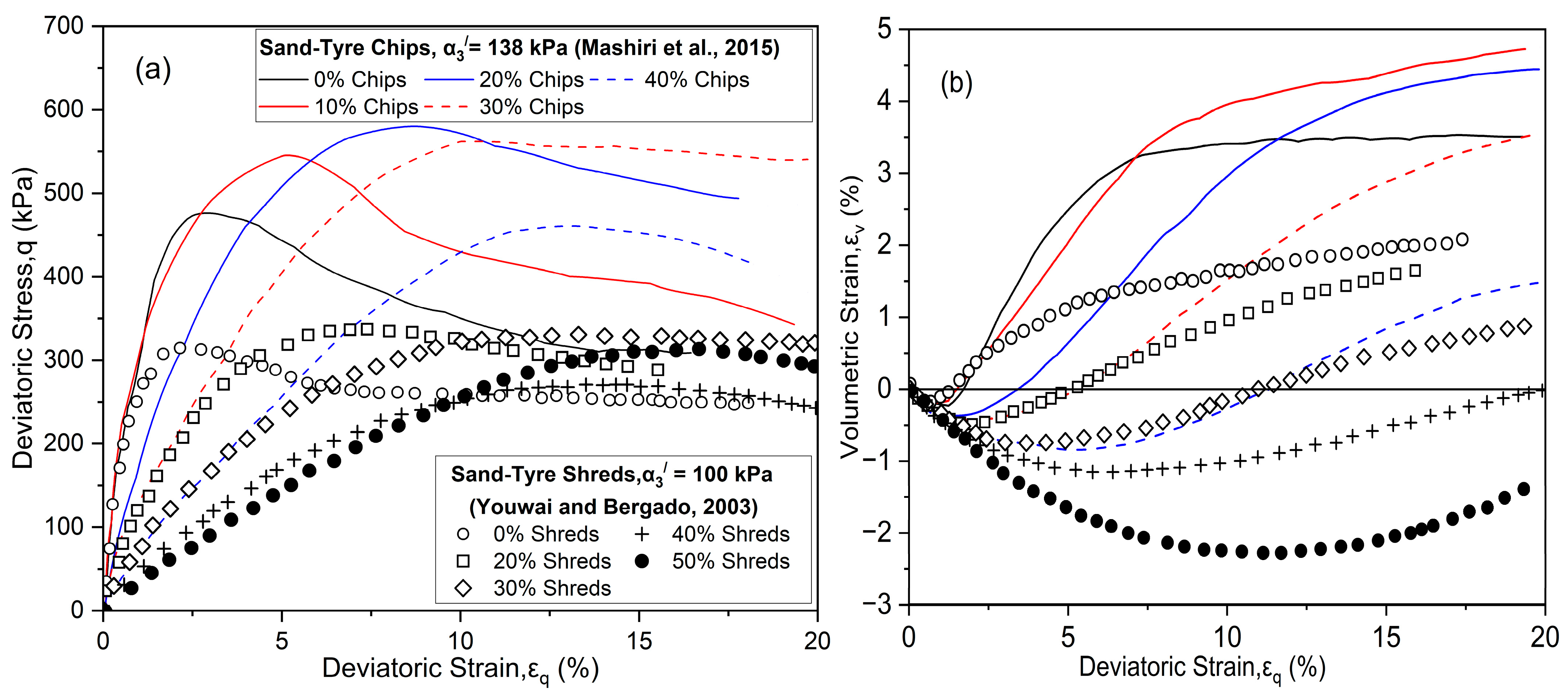
2.1. Stress–Strain Behaviour
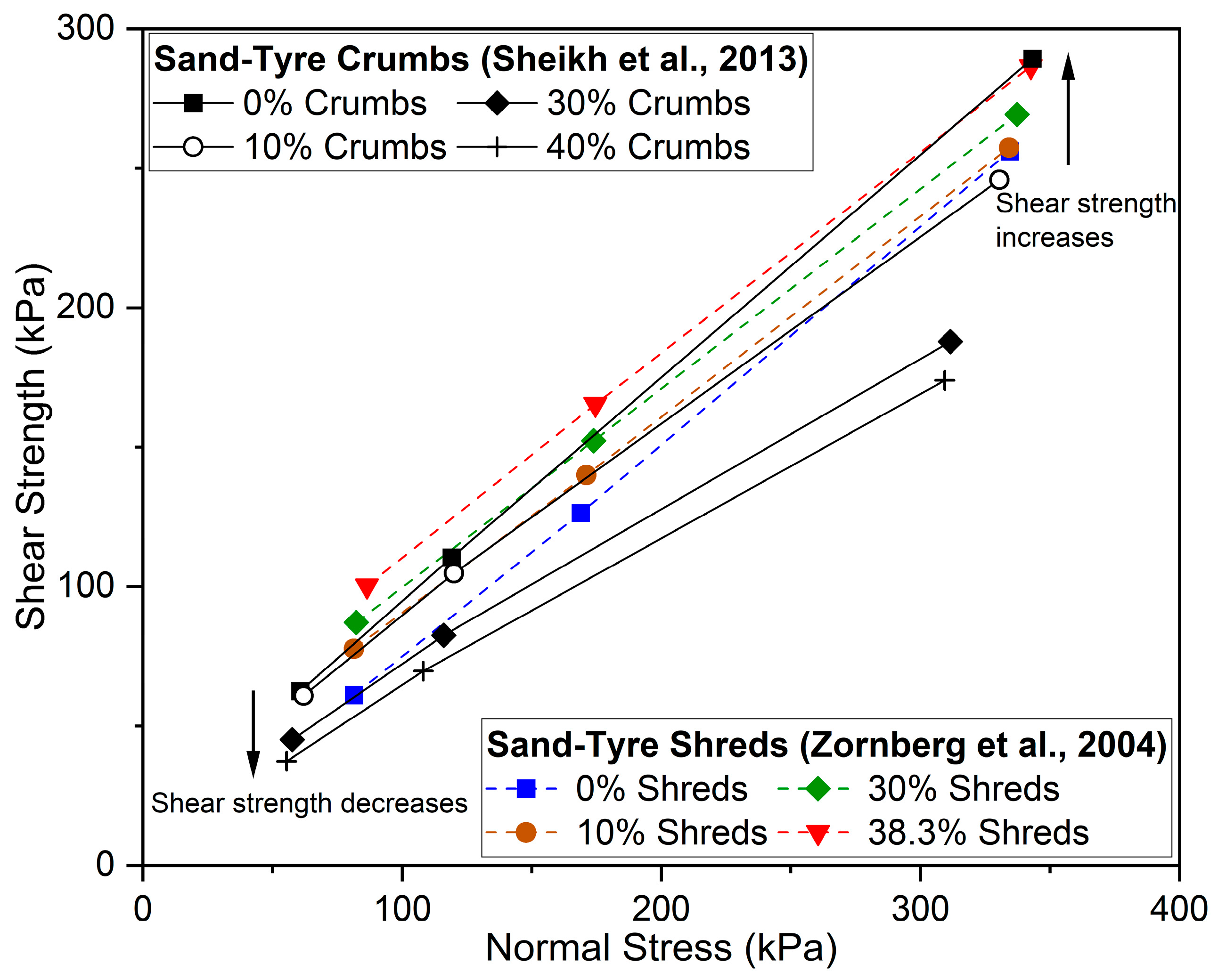
2.2. Shear Strength

| Effect Type | Reference | Mixtures | Rubber Content (%) | Test/Apparatus | Optimal Rubber Content Considering Shear Strength |
|---|---|---|---|---|---|
| Positive effect | Ahmed [93] | Sand–tyre rubber | 0–100 | Static and dynamic triaxial test | 39% by mass |
| Edil and Bosscher [80] | Sand–scrap tyre | 5, 10, 25 | Large-scale direct shear test | 10% by volume (5% by mass) | |
| Tatlisoz et al. [81] | Silty sand–rubber chips/shreds | 10, 20, 30 | Large-scale direct shear test | At least 30% of rubber chip content | |
| Foose et al. [79] | Sand–tyre shreds | 0, 10, 20, 30 | Direct shear test | 30% rubber content maximized shear strength | |
| Zornberg et al. [84] | Sand–tyre shreds | 0, 5, 10, 15, 30, 38, 60, 100 | Large-scale triaxial test | 35% of tyre shreds by mass | |
| Ghazavi and Sakhi [82] | Sand–rubber shreds | 15, 30, 50 | Large-scale direct shear test | Friction angle peaks at 50% rubber shreds | |
| Rao and Dutta [98] | Sand–tyre chips | 0, 5, 10, 15, 20, 30, 40, 60, 80, 100 | Drained triaxial test; repetitive load test | 20% by mass | |
| Mashiri et al. [85] | Sand–tyre chips | 0, 10, 20, 30, 35, 40 | Consolidated drained monotonic triaxial | 35% by mass | |
| Anbazhagan et al. [95] | Sand–tyre chips | 10, 15, 20, 25, 30, 35 | Large-scale direct shear test | 30% by volume | |
| Ahmed et al. [87] | Sand–tyre chips | 0, 10, 20, 30, 40 | Constant shear-drained stress path | 20% by mass | |
| Negative effect | Lee et al. [83] | Sand–tyre chips | 40 | Consolidated drained triaxial test | Shear strength falls between sand and pure tyre chips |
| Youwai and Bergado [94] | Sand–tyre rubber shreds | 0, 20, 30, 40, 50, 100% | Isotropic consolidated drained triaxial test | Shear strength decreases as tyre content increases | |
| Sheikh et al. [86] | Sand–tyre crumbs | 0, 10, 20, 30, 40 | Static triaxial test | Shear strength decreases as tyre content increases | |
| Indraratna et al. [42] | CW + SFS + rubber crumbs | 0, 10, 20, 30, 40 | Monotonic triaxial; drained cyclic triaxial | Shear strength decreases as crumb content increases | |
| Tawk and Indraratna [58] | CW + rubber crumbs | 0, 5, 10, 15 | Drained static triaxial | Shear strength decreases as crumb content increases |
3. Constitutive Models for Materials Mixed with Rubber
3.1. Constitutive Models for Sand–Rubber Mixtures
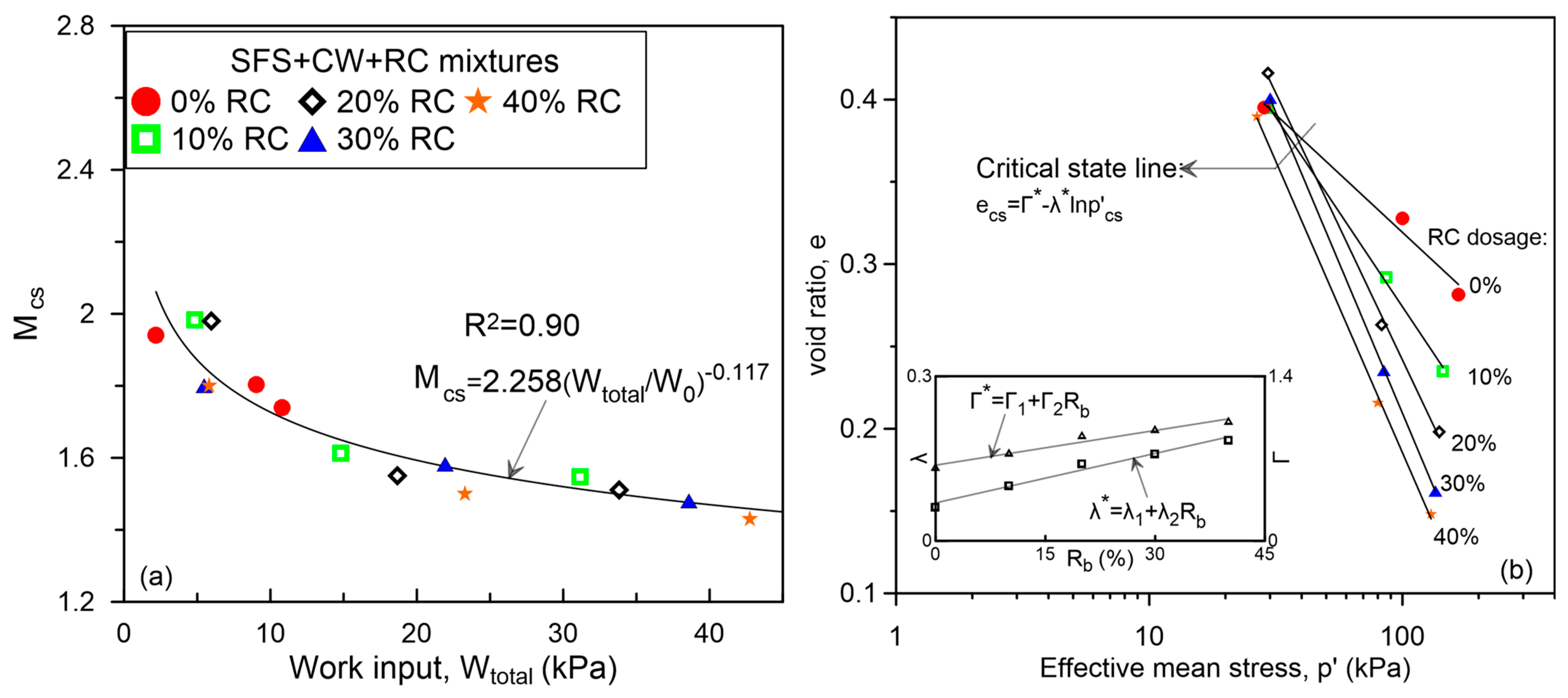
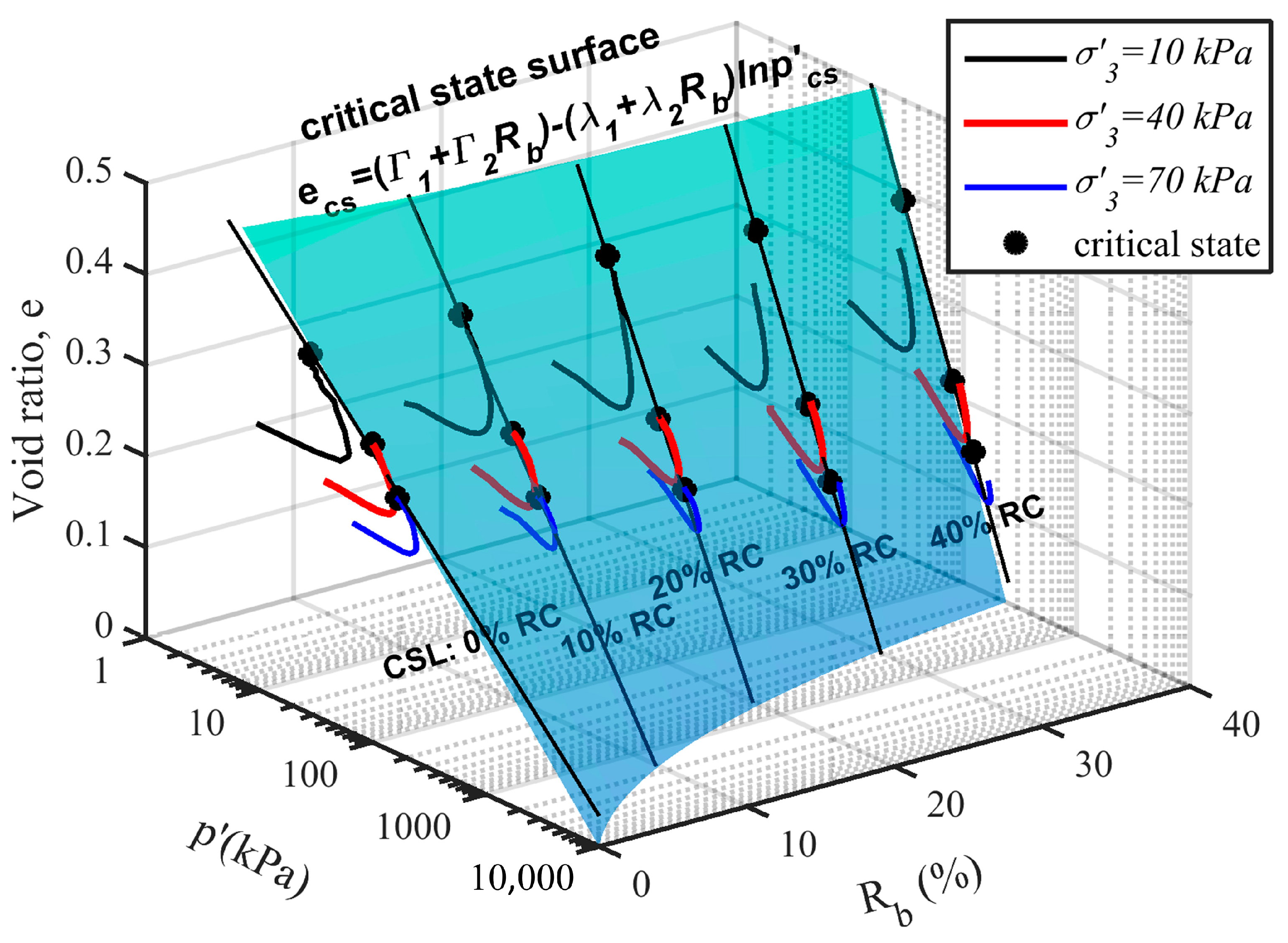
3.2. Dilatancy Model for SFS + CW + RC Mixtures
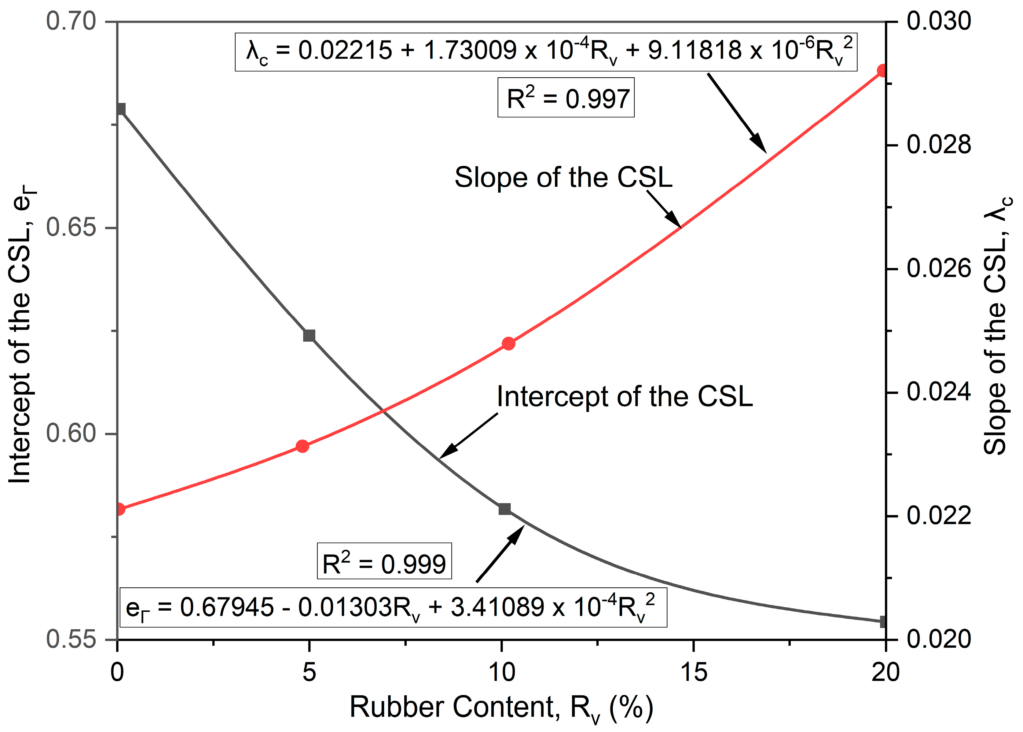
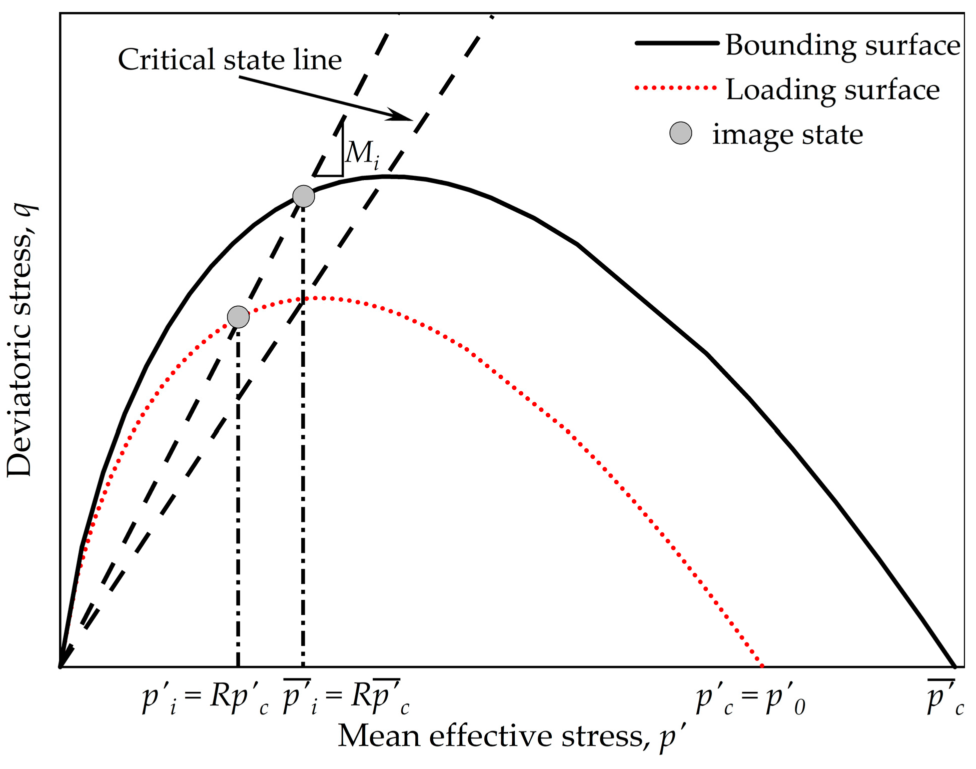
3.3. Constitutive Model for CW + RC Mixtures
4. Model Limitations and Applications
5. Conclusions and Recommendations
- The shear behaviour of rubber and granular mixtures is primarily governed by the confining pressure and the amount of (shredded) rubber tyres. The inclusion of rubber in granular soil mixtures significantly influences the stress–strain response, improves its energy absorption ability, increases its ductility, and reduces its dilative behaviour. Moreover, the shear strength of materials mixed with rubber depends on the type and amount of rubber and the confining pressure. While including rubber shreds and chips in the mixtures enhances the shear strength through particle interlocking, the addition of rubber crumbs tends to reduce the shear strength due to its lack of structural reinforcement;
- The constitutive models developed for mixtures of sand and rubber lightweight backfill material highlight the significant advancements in predicting stress–strain behaviour. The early hyperbolic model struggled with post-peak softening and dilatancy. To overcome these limitations, the hypoplastic model was developed by incorporating state-dependent behaviour to enable the prediction of dilative and compressive behaviour. Critical state and bounding surface plasticity models further refined these predictions by accounting for variations in the amount of rubber and capturing the hardening and softening in mixtures of sand and rubber. An empirical model was also developed to estimate the dynamic shear modulus;
- The dilatancy model developed for mixtures of SFS + CW + RC to be used as a railway capping layer within the critical-state framework also captured the energy absorbing properties of the mixture due to inclusion of rubber and its influence on dilatancy behaviour. Unlike conventional granular materials the critical-state parameters varied with the amount of rubber due to changes in its energy absorption capacity. The predicted stress–strain behaviour of the mixture aligned well with the laboratory observations;
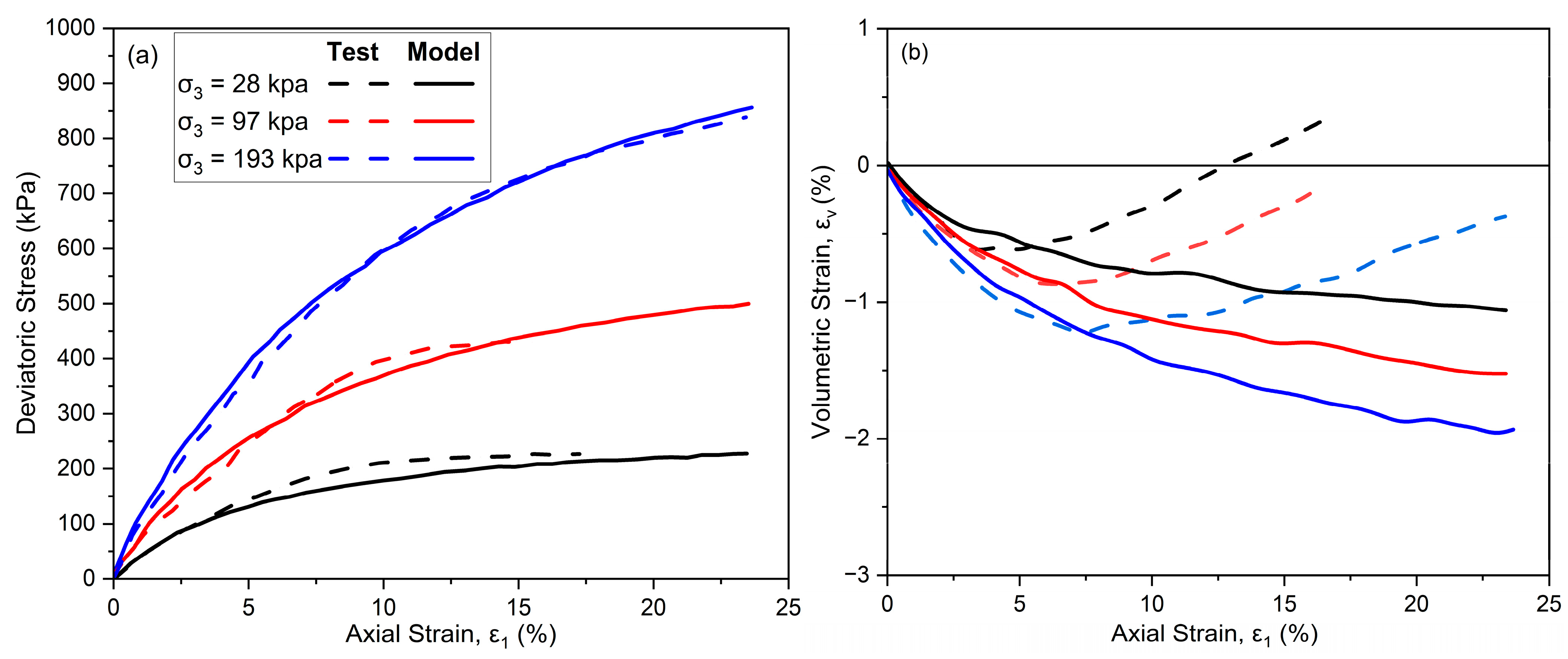
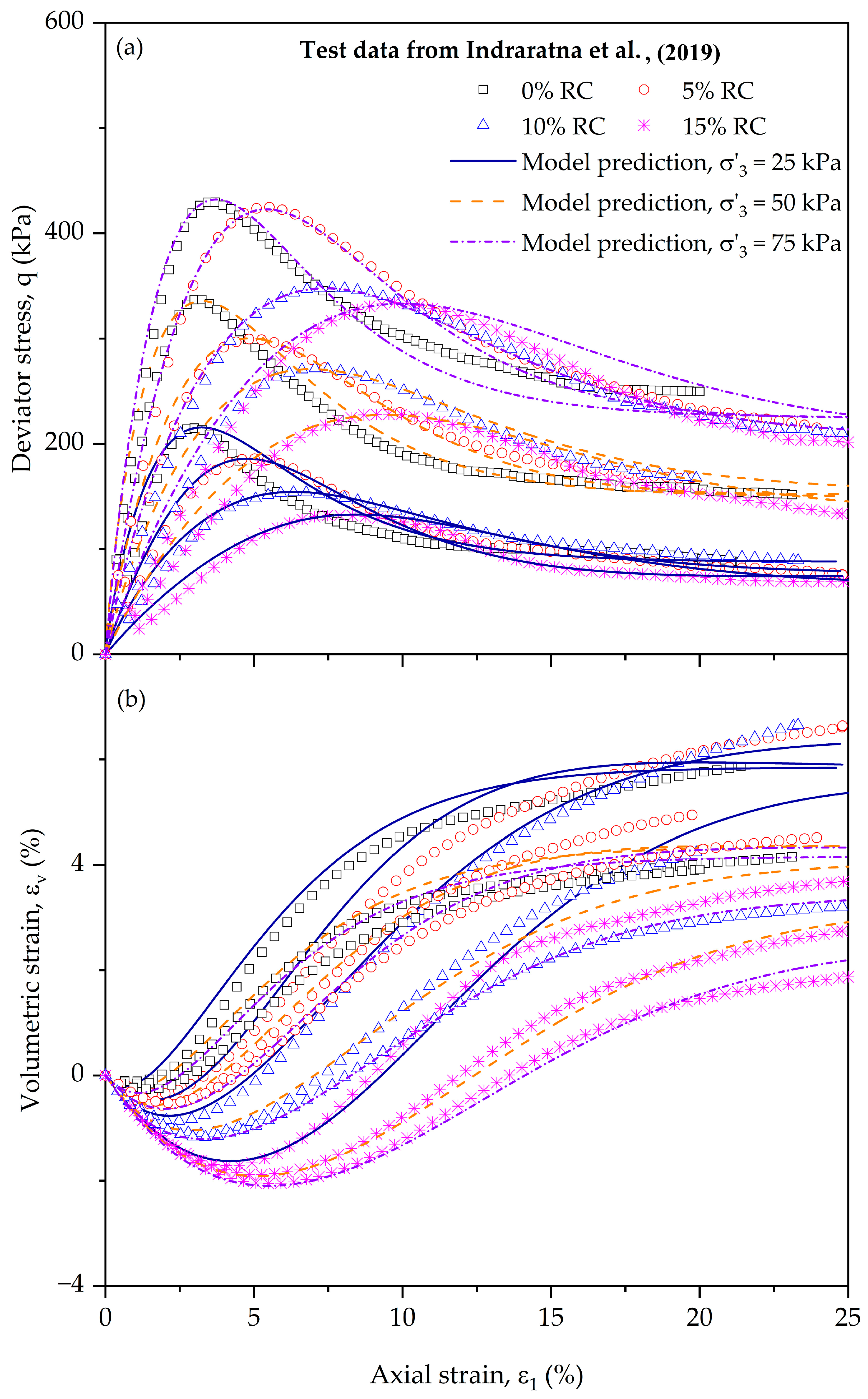
- The constitutive model for mixtures of CW + RC predicted the stress–strain behaviour of mining waste and rubber crumbs using a bounding surface plasticity approach with a compressibility-dependent void ratio to consider the effect of rubber inclusion on the volumetric deformation of the mixture and an image of the critical state. An image-state ratio-based plastic flow rule and a hardening modulus that depends on the amount of rubber and the confining pressure were used to model the stress–strain behaviour. The model remains suitable for capping layers involved with rubber particles, though further refinements are needed to better account for the internal deformation of rubber within the granular matrix.
Author Contributions
Funding
Data Availability Statement
Acknowledgments
Conflicts of Interest
Abbreviations
| CSL | Critical-state line |
| CSR | Constant stress ratio |
| CW | Coal wash |
| RC | Rubber crumbs |
| SFS | Steel furnace slags |
| UBM | Under-ballast mats |
| USP | Under-sleeper pads |
| a, b, c | Curve-fitting parameters |
| d | Dilatancy |
| d0, kd, m | Dilatancy parameters |
| Dp | Plastic dilatancy |
| Plastic dilatancy at the peak deviator stress | |
| e, e* | Void ratio, modified void ratio |
| eCS | Void ratio at the critical state |
| Intercept of the CSL | |
| Ei | Initial tangent of Young’s modulus |
| G | Elastic shear modulus |
| G0 | Elastic model parameter |
| Gdmax | Maximum shear modulus |
| GS,CW, GS,RC | Specific gravities of CW and RC |
| Hmin | Minimum hardening modulus at |
| H* | Hardening modulus parameter |
| K | Elastic bulk modulus |
| KP | Plastic modulus |
| Hardening modulus | |
| Critical-state stress ratio, modified critical-state stress ratio | |
| Equivalent stress ratio at the constant stress state | |
| M0 | Critical-state ratio when total work input is equal to 1 kPa |
| N | Volumetric coupling parameter |
| p, p′ | Mean stress, effective mean stress |
| pa | Atmospheric pressure |
| pr | Reference stress (=1 kPa) |
| p′CS | Effective mean stress at the critical state |
| Intercept between the loading surface and bounding surface with the q = 0 axis | |
| q, qult | Deviatoric stress, ultimate deviatoric stress |
| R | Material constant |
| Rb, RV | Rubber content by mass and rubber content by volume |
| Wtotal | Total work input |
| W0 | Unit work input |
| α | Material constants |
| Curve-fitting parameters | |
| Diminution of H with the amount of rubber | |
| , , | Axial strain, deviatoric strain, volumetric strain |
| Increments of deviator, volumetric strain | |
| Increments of total deviatoric, total volumetric strain | |
| Increments in plastic deviatoric, plastic volumetric strain | |
| Void volumetric strain | |
| Γ | Void ratio at pr |
| Γ* | Modified void ratio at p′CS = 1 kPa |
| Γ1, Γ2 | Calibration parameters for |
| Stress ratio, yield stress ratio | |
| Gradient of the swelling line | |
| Gradient of the critical-state void ratio line | |
| Slope of the critical-state line | |
| Gradient of the modified critical-state line | |
| Calibration parameters for | |
| State parameter, modified state parameter, state parameter at the image state | |
| Dilatancy constant at the image state condition | |
| Effective confining pressure | |
| ∂q | Increment of deviatoric stress |
| ∂p′ | Increment of mean effective stress |
References
- Gharehbaghi, K.; McManus, K.; Robson, K.; Paterno, D.; Myers, M. High-speed rail transportation: Key factors for the Australian eastern states. World Rev. Intermodal Transp. Res. 2020, 9, 174–197. [Google Scholar] [CrossRef]
- Zhai, W.; Wei, K.; Song, X.; Shao, M. Experimental investigation into ground vibrations induced by very high-speed trains on a non-ballasted track. Soil Dyn. Earthq. Eng. 2015, 72, 24–36. [Google Scholar] [CrossRef]
- Qi, Y.; Indraratna, B.; Ngo, T.; Arachchige, C.M.K.; Hettiyahandi, S. Sustainable solutions for railway using recycled rubber. Transp. Geotech. 2024, 46, 101256. [Google Scholar] [CrossRef]
- Kim, M.; Tutumluer, E.; Kwon, J. Nonlinear Pavement Foundation Modeling for Three-Dimensional Finite-Element Analysis of Flexible Pavements. Int. J. Geomech. 2009, 9, 195–208. [Google Scholar] [CrossRef]
- Kodikara, J.; Islam, T.; Sounthararajah, A. Review of soil compaction: History and recent developments. Transp. Geotech. 2018, 17, 24–34. [Google Scholar] [CrossRef]
- Liu, L.; Li, Z.; Cai, G.; Geng, X.; Dai, B. Performance and prediction of long-term settlement in road embankments constructed with recycled construction and demolition waste. Acta Geotech. 2022, 17, 4069–4093. [Google Scholar] [CrossRef]
- Indraratna, B.; Salim, W. Deformation and Degradation Mechanics of Recycled Ballast Stabilised with Geosynthetics. Soils Found. 2003, 43, 35–46. [Google Scholar] [CrossRef]
- Zhao, C.; Xie, Z.; Yu, F.; Zhu, C.; Bian, X.; Chen, Y. Breakage characteristics of ballast particle in uniaxial compression tests incorporating shape and size effects. Constr. Build. Mater. 2024, 447, 138155. [Google Scholar] [CrossRef]
- Indraratna, B.; Lackenby, J.; Christie, D. Effect of confining pressure on the degradation of ballast under cyclic loading. Géotechnique 2005, 55, 325–328. [Google Scholar] [CrossRef]
- Arachchige, C.M.K.; Indraratna, B.; Qi, Y.; Vinod, J.S.; Rujikiatkamjorn, C. Deformation and degradation behaviour of Rubber Intermixed Ballast System under cyclic loading. Eng. Geol. 2022, 307, 106786. [Google Scholar] [CrossRef]
- Wong, C.P.Y.; Coop, M.R. The contact mechanics of a UK railway ballast. Géotechnique 2023, 74, 1700–1712. [Google Scholar] [CrossRef]
- Zhai, W.M.; Wang, K.Y.; Lin, J.H. Modelling and experiment of railway ballast vibrations. J. Sound Vib. 2004, 270, 673–683. [Google Scholar] [CrossRef]
- Qi, Y.; Indraratna, B. Influence of Rubber Inclusion on the Dynamic Response of Rail Track. J. Mater. Civ. Eng. 2022, 34, 04021432. [Google Scholar] [CrossRef]
- Milne, D.R.M.; Le Pen, L.M.; Thompson, D.J.; Powrie, W. Properties of train load frequencies and their applications. J. Sound Vib. 2017, 397, 123–140. [Google Scholar] [CrossRef]
- Nguyen, T.; Indraratna, B.; Kelly, R.; Phan, N.M.; Haryono, F. Mud pumping under rail tracks: Mechanisms, Assessments, and solutions. Aust. Geomech. J. 2019, 54, 59–80. [Google Scholar]
- Bian, X.; Wan, Z.; Zhao, C.; Cui, Y.; Chen, Y. Mud pumping in the roadbed of ballastless high-speed railway. Géotechnique 2023, 73, 614–628. [Google Scholar] [CrossRef]
- Indraratna, B.; Singh, M.; Nguyen, T. The mechanism and effects of subgrade fluidisation under ballasted railway tracks. Railw. Eng. Sci. 2020, 28, 113–128. [Google Scholar] [CrossRef]
- Tennakoon, N.; Indraratna, B.; Rujikiatkamjorn, C.; Nimbalkar, S.; Neville, T. The Role of Ballast Fouling Characteristics on the Drainage Capacity of Rail Substructure. Geotech. Test. J. 2012, 35, 629–640. [Google Scholar] [CrossRef]
- Nimbalkar, S.S.; Tennakoon, N.; Indraratna, B. Effects of Fouling and Degradation on Geotechnical Behaviour of Railway Ballast. In Proceedings of the Indian Geotechnical Conference (IGC 2015): Geotechnics for Infrastructure and Foundation Techniques (GIFT), Pune, India, 17–19 December 2015. [Google Scholar]
- Le Pen, L.M.; Powrie, W. Contribution of Base, Crib, and Shoulder Ballast to the Lateral Sliding Resistance of Railway Track: A Geotechnical Perspective. Proc. Inst. Mech. Engineers. Part F J. Rail Rapid Transit 2011, 225, 113–128. [Google Scholar] [CrossRef]
- Vale, C. Wheel Flats in the Dynamic Behavior of Ballasted and Slab Railway Tracks. Appl. Sci. 2021, 11, 7127. [Google Scholar] [CrossRef]
- Sattari, S.; Saadat, M.; Mirtalaie, S.H.; Salehi, M.; Soleimani, A. Effects of train speed, track irregularities, and wheel flat on wheel-rail dynamic forces. Int. J. Heavy Veh. Syst. 2023, 30, 734–751. [Google Scholar] [CrossRef]
- Indraratna, B.; Qi, Y.; Ngo, T.N.; Rujikiatkamjorn, C.; Neville, T.; Ferreira, F.B.; Shahkolahi, A. Use of Geogrids and Recycled Rubber in Railroad Infrastructure for Enhanced Performance. Geosciences 2019, 9, 30. [Google Scholar] [CrossRef]
- Afrin, H.; Huda, N.; Abbasi, R. Study on End-of-Life Tires (ELTs) Recycling Strategy and Applications. IOP Conf. Ser. Mater. Sci. Eng. 2021, 1200, 12009. [Google Scholar] [CrossRef]
- Tyre Stewardship Australia. Australian Tyre Consumption and Recovery 2023–2024. Australian Government Accredited Product Stewardship Scheme. 2025. Available online: https://www.tyrestewardship.org.au/wp-content/uploads/2025/01/Australian-Tyre-Consumption-and-Recovery-2023-24.pdf (accessed on 11 March 2025).
- Indraratna, B.; Qi, Y.; Ngo, T.; Malisetty, R.; Arachchige, C.K. Innovative and cost-effective rail track construction using recycled rubber. Railw. Eng. Sci. 2024. [Google Scholar] [CrossRef]
- Indraratna, B.; Qi, Y.; Rujikiatkamjorn, C. Waste Materials Utilisation for Transport Infrastructure, 1st ed.; Taylor & Francis Group: Milton, ON, Canada, 2025. [Google Scholar]
- Naeini, M.; Mohammadinia, A.; Arulrajah, A.; Horpibulsuk, S. Recycled Glass Blends with Recycled Concrete Aggregates in Sustainable Railway Geotechnics. Sustainability 2021, 13, 2463. [Google Scholar] [CrossRef]
- Mohajerani, A.; Vajna, J.; Cheung, T.H.H.; Kurmus, H.; Arulrajah, A.; Horpibulsuk, S. Practical recycling applications of crushed waste glass in construction materials: A review. Constr. Build. Mater. 2017, 156, 443–467. [Google Scholar] [CrossRef]
- Arulrajah, A.; Ali, M.; Disfani, M. Recycled-Glass Blends in Pavement Base/Subbase Applications: Laboratory and Field Evaluation. J. Mater. Civ. Eng. 2013, 26, 04014025. [Google Scholar] [CrossRef]
- Perera, S.T.A.; Saberian, M.; Zhu, J.; Roychand, R.; Li, J. Effect of crushed glass on the mechanical and microstructural behavior of highly expansive clay subgrade. Case Stud. Constr. Mater. 2022, 17, e01244. [Google Scholar] [CrossRef]
- Disfani, M.M.; Arulrajah, A.; Bo, M.W.; Hankour, R. Recycled crushed glass in road work applications. Waste Manag. (Elmsford) 2011, 31, 2341–2351. [Google Scholar] [CrossRef]
- Arulrajah, A.; Ali, M.M.Y.; Disfani, M.M.; Piratheepan, J. Suitability of Using Recycled Glass-Crushed Rock Blends for Pavement Subbase Applications; ASCE: Reston, VA, USA, 2011; pp. 1325–1334. [Google Scholar]
- Arulrajah, A.; Yaghoubi, E.; Wong, Y.C.; Horpibulsuk, S. Recycled plastic granules and demolition wastes as construction materials: Resilient moduli and strength characteristics. Constr. Build. Mater. 2017, 147, 639–647. [Google Scholar] [CrossRef]
- Hasheminezhad, A.; Farina, A.; Yang, B.; Ceylan, H.; Kim, S.; Tutumluer, E.; Cetin, B. The utilization of recycled plastics in the transportation infrastructure systems: A comprehensive review. Constr. Build. Mater. 2024, 411, 134448. [Google Scholar] [CrossRef]
- Peddaiah, S.; Burman, A.; Sreedeep, S. Experimental Study on Effect of Waste Plastic Bottle Strips in Soil Improvement. Geotech. Geol. Eng. 2018, 36, 2907–2920. [Google Scholar] [CrossRef]
- Kaliboullah, C.I.; Indraratna, B.; Heitor, A.; Rujikiatkamjorn, C. Evaluation of Coalwash as a Potential Structural Fill Material for Port Reclamation. In Proceedings of the 12th Australia—New Zealand Conference on Geomechanics, Wellington, New Zealand, 22–25 February 2015. [Google Scholar]
- Chiaro, G.; Indraratna, B.; Tasalloti, S.M.A. Predicting the behaviour of coal wash and steel slag mixtures under triaxial conditions. Can. Geotech. J. 2015, 52, 367–373. [Google Scholar] [CrossRef]
- Rujikiatkamjorn, C.; Indraratna, B.; Chiaro, G. Compaction of coal wash to optimise its utilisation as water-front reclamation fill. Geomech. Geoengin. Int. J. 2013, 8, 36–45. [Google Scholar] [CrossRef]
- Heitor, A.; Indraratna, B.; Kaliboullah, C.I.; Rujikiatkamjorn, C.; McIntosh, G.W. Drained and Undrained Shear Behavior of Compacted Coal Wash. J. Geotech. Geoenviron. Eng. 2016, 142, 04016006. [Google Scholar] [CrossRef]
- Qi, Y.; Indraratna, B.; Vinod, J.S. Behavior of Steel Furnace Slag, Coal Wash, and Rubber Crumb Mixtures with Special Relevance to Stress–Dilatancy Relation. J. Mater. Civ. Eng. 2018, 30, 04018276. [Google Scholar] [CrossRef]
- Indraratna, B.; Qi, Y.; Heitor, A. Evaluating the Properties of Mixtures of Steel Furnace Slag, Coal Wash, and Rubber Crumbs Used as Subballast. J. Mater. Civ. Eng. 2018, 30, 04017251. [Google Scholar] [CrossRef]
- Tawk, M.; Qi, Y.; Indraratna, B.; Rujikiatkamjorn, C.; Heitor, A. Behavior of a Mixture of Coal Wash and Rubber Crumbs under Cyclic Loading. J. Mater. Civ. Eng. 2021, 33, 04021054. [Google Scholar] [CrossRef]
- Tasalloti, S.M.A.; Indraratna, B.; Rujikiatkamjorn, C.; Heitor, A.; Chiaro, G. A Laboratory Study on the Shear Behavior of Mixtures of Coal Wash and Steel Furnace Slag as Potential Structural Fill. Geotech. Test. J. 2015, 38, 361–372. [Google Scholar] [CrossRef]
- Chiaro, G.; Indraratna, B.; Tasalloti, S.M.A.; Rujikiatkamjorn, C. Optimisation of coal wash–slag blend as a structural fill. Proc. Inst. Civ. Engineers. Ground Improv. 2015, 168, 33–44. [Google Scholar] [CrossRef]
- Xue, Y.; Wu, S.; Hou, H.; Zha, J. Experimental investigation of basic oxygen furnace slag used as aggregate in asphalt mixture. J. Hazard. Mater. 2006, 138, 261–268. [Google Scholar] [CrossRef]
- Chien, H.-T.; Chang, J.-R.; Hsu, H.-M. Determining the content of steel furnace slag in asphalt concrete. Case Stud. Constr. Mater. 2023, 19, e02399. [Google Scholar] [CrossRef]
- Pasetto, M.; Baliello, A.; Giacomello, G.; Pasquini, E. The Use of Steel Slags in Asphalt Pavements: A State-of-the-Art Review. Sustainability 2023, 15, 8817. [Google Scholar] [CrossRef]
- Wang, D.; Tawk, M.; Indraratna, B.; Heitor, A.; Rujikiatkamjorn, C. A mixture of coal wash and fly ash as a pavement substructure material. Transp. Geotech. 2019, 21, 100265. [Google Scholar] [CrossRef]
- Kim, B.; Prezzi, M.; Salgado, R. Geotechnical Properties of Fly and Bottom Ash Mixtures for Use in Highway Embankments. J. Geotech. Geoenviron. Eng. 2005, 131, 914–924. [Google Scholar] [CrossRef]
- Baykal, G.; Edinçliler, A.; Saygılı, A. Highway embankment construction using fly ash in cold regions. Resour. Conserv. Recycl. 2004, 42, 209–222. [Google Scholar] [CrossRef]
- Arulrajah, A.; Disfani, M.M.; Horpibulsuk, S.; Suksiripattanapong, C.; Prongmanee, N. Physical properties and shear strength responses of recycled construction and demolition materials in unbound pavement base/subbase applications. Constr. Build. Mater. 2014, 58, 245–257. [Google Scholar] [CrossRef]
- Arulrajah, A.; Piratheepan, J.; Aatheesan, T.; Bo, M.W. Geotechnical Properties of Recycled Crushed Brick in Pavement Applications. J. Mater. Civ. Eng. 2011, 23, 1444–1452. [Google Scholar] [CrossRef]
- Ahmad, F.; Mujah, D.; Hazarika, H.; Safari, A. Assessing the potential reuse of recycled glass fibre in problematic soil applications. J. Clean. Prod. 2012, 35, 102–107. [Google Scholar] [CrossRef]
- Alfayez, S.A.; Suleiman, A.R.; Nehdi, M.L. Recycling Tire Rubber in Asphalt Pavements: State of the Art. Sustainability 2020, 12, 9076. [Google Scholar] [CrossRef]
- Shu, X.; Huang, B. Recycling of waste tire rubber in asphalt and portland cement concrete: An overview. Constr. Build. Mater. 2014, 67, 217–224. [Google Scholar] [CrossRef]
- Qi, Y.; Indraratna, B. Energy-Based Approach to Assess the Performance of a Granular Matrix Consisting of Recycled Rubber, Steel-Furnace Slag, and Coal Wash. J. Mater. Civ. Eng. 2020, 32, 04020169. [Google Scholar] [CrossRef]
- Tawk, M.; Indraratna, B. Role of Rubber Crumbs on the Stress-Strain Response of a Coal Wash Matrix. J. Mater. Civ. Eng. 2021, 33, 04020480. [Google Scholar] [CrossRef]
- Indraratna, B.; Qi, Y.; Tawk, M.; Heitor, A.; Rujikiatkamjorn, C.; Navaratnarajah, S.K. Advances in ground improvement using waste materials for transportation infrastructure. Proc. Inst. Civ. Eng. Ground Improv. 2022, 175, 3–22. [Google Scholar] [CrossRef]
- Sol-Sánchez, M.; Thom, N.H.; Moreno-Navarro, F.; Rubio-Gámez, M.C.; Airey, G.D. A study into the use of crumb rubber in railway ballast. Constr. Build. Mater. 2015, 75, 19–24. [Google Scholar] [CrossRef]
- Qiang, W.; Jing, G.; Connolly, D.P.; Aela, P. The use of recycled rubber in ballasted railway tracks: A review. J. Clean. Prod. 2023, 420, 138339. [Google Scholar] [CrossRef]
- Qi, Y.; Indraratna, B. The effect of adding rubber crumbs on the cyclic permanent deformation of waste mixtures containing coal wash and steel furnace slag. Géotech. 2022, 73, 951–960. [Google Scholar] [CrossRef]
- Indraratna, B.; Sun, Q.; Grant, J. Behaviour of subballast reinforced with used tyre and potential application in rail tracks. Transp. Geotech. 2017, 12, 26–36. [Google Scholar] [CrossRef]
- Indraratna, B.; Sun, Q.; Heitor, A.; Grant, J. Performance of Rubber Tire-Confined Capping Layer under Cyclic Loading for Railroad Conditions. J. Mater. Civ. Eng. 2018, 30, 06017021. [Google Scholar] [CrossRef]
- Indraratna, B.; Mehmood, F.; Ngo, T.; Rujikiatkamjorn, C.; Grant, J. Performance of Tire Cell Foundation as a Subballast Capping Layer under Cyclic Train Loading. J. Geotech. Geoenviron. Eng. 2025, 151, 04024134. [Google Scholar] [CrossRef]
- Indraratna, B.; Ngo, T.; Bessa Ferreira, F.; Rujikiatkamjorn, C.; Shahkolahi, A. Laboratory examination of ballast deformation and degradation under impact loads with synthetic inclusions. Transp. Geotech. 2020, 25, 100406. [Google Scholar] [CrossRef]
- Siddiqui, A.R.; Indraratna, B.; Ngo, T.; Rujikiatkamjorn, C. Laboratory assessment of rubber grid-reinforced ballast under impact testing. Géotech. Lett. 2023, 13, 118–128. [Google Scholar] [CrossRef]
- Ngo, T.; Indraratna, B. Use of Geogrid for Improved Performance of Ballasted Tracks: Experimental and DEM Approaches. Int. J. Geosynth. Ground Eng. 2024, 10, 33. [Google Scholar] [CrossRef]
- Mayuranga, H.G.S.; Navaratnarajah, S.K.; Bandara, C.S.; Jayasinghe, J.A.S.C. Elastic inclusions in ballasted tracks—A review and recommendations. Int. J. Rail Transp. (Online) 2024, 12, 253–280. [Google Scholar] [CrossRef]
- Sol-Sánchez, M.; Moreno-Navarro, F.; Gámez, M. The use of deconstructed tire rail pads in railroad tracks: Impact of pad thickness. Mater. Des. 2014, 58, 198–203. [Google Scholar] [CrossRef]
- Navaratnarajah, S.K.; Indraratna, B.; Ngo, N.T. Influence of Under Sleeper Pads on Ballast Behavior Under Cyclic Loading: Experimental and Numerical Studies. J. Geotech. Geoenviron. Eng. 2018, 144, 45–72. [Google Scholar] [CrossRef]
- Navaratnarajah, S.K.; Indraratna, B. Use of Rubber Mats to Improve the Deformation and Degradation Behavior of Rail Ballast under Cyclic Loading. J. Geotech. Geoenviron. Eng. 2017, 143, 04017015. [Google Scholar] [CrossRef]
- Alves Costa, P.; Calçada, R.; Silva Cardoso, A. Ballast mats for the reduction of railway traffic vibrations. Numerical study. Soil Dyn. Earthq. Eng. 2012, 42, 137–150. [Google Scholar] [CrossRef]
- Jayasuriya, C.; Indraratna, B.; Ngoc Ngo, T. Experimental study to examine the role of under sleeper pads for improved performance of ballast under cyclic loading. Transp. Geotech. 2019, 19, 61–73. [Google Scholar] [CrossRef]
- Indraratna, B.; Qi, Y.; Jayasuriya, C.; Rujikiatkamjorn, C.; Arachchige, C.M.K. Use of recycled rubber inclusions with granular waste for enhanced track performance. Transp. Eng. 2021, 6, 100093. [Google Scholar] [CrossRef]
- Esmaeili, M.; Farsi, S.; Shamohammadi, A. Effect of rock strength on the degradation of ballast equipped with under sleeper pad. Constr. Build. Mater. 2022, 321, 126413. [Google Scholar] [CrossRef]
- Riyad, A.S.M.; Indraratna, B.; Qi, Y.; Tawk, M. Constitutive behaviour of a granular matrix containing coal mine waste intermixed with rubber crumbs. Acta Geotech. 2024, 20, 185–196. [Google Scholar] [CrossRef]
- Ahmed, I.; Lovell, C.W. Rubber Soils as Lightweight Geomaterials; Transportation Research Record No. 1422; Transportation Research Board: Washington, DC, USA, 1993; pp. 61–70. [Google Scholar]
- Foose, G.J.; Benson, C.H.; Bosscher, P.J. Sand Reinforced with Shredded Waste Tires. J. Geotech. Eng. 1996, 122, 760–767. [Google Scholar] [CrossRef]
- Edil, T.B.; Bosscher, P.J. Engineering Properties of Tire Chips and Soil Mixtures. Geotech. Test. J. 1994, 17, 453–464. [Google Scholar] [CrossRef]
- Tatlisoz, N.; Edil, T.B.; Benson, C.H. Interaction between Reinforcing Geosynthetics and Soil-Tire Chip Mixtures. J. Geotech. Geoenviron. Eng. 1998, 124, 1109–1119. [Google Scholar] [CrossRef]
- Ghazavi, M.; Sakhi, M.A. Influence of Optimized Tire Shreds on Shear Strength Parameters of Sand. Int. J. Geomech. 2005, 5, 58–65. [Google Scholar] [CrossRef]
- Lee, J.; Salgado, R.; Bernal, A.; Lovell, C.W. Shredded Tires and Rubber-Sand as Lightweight Backfill. J. Geotech. Geoenviron. Eng. 1999, 125, 132–141. [Google Scholar] [CrossRef]
- Zornberg, J.G.; Cabral, A.R.; Viratjandr, C. Behaviour of shred-sand mixtures. Can. Geotech. J. 2004, 41, 227–241. [Google Scholar] [CrossRef]
- Mashiri, M.; Vinod, J.; Sheikh, M.N.; Tsang, H. Shear strength and dilatancy behaviour of sand–tyre chip mixtures. Soils Found. 2015, 55, 517–528. [Google Scholar] [CrossRef]
- Sheikh, M.N.; Mashiri, M.S.; Vinod, J.S.; Tsang, H. Shear and Compressibility Behavior of Sand–Tire Crumb Mixtures. J. Mater. Civ. Eng. 2013, 25, 1366–1374. [Google Scholar] [CrossRef]
- Ahmed, S.; Vinod, J.S.; Sheikh, M.N. Behavior of Sand–Tire Chip Mixtures in Constant Shear Drained Stress Path. J. Mater. Civ. Eng. 2022, 34, 04022294. [Google Scholar] [CrossRef]
- Qi, Y.; Indraratna, B.; Heitor, A.; Vinod, J.S. Effect of Rubber Crumbs on the Cyclic Behavior of Steel Furnace Slag and Coal Wash Mixtures. J. Geotech. Geoenviron. Eng. 2018, 144, 04017107. [Google Scholar] [CrossRef]
- Qi, Y.; Indraratna, B.; Vinod, J.S. Dynamic Properties of Mixtures of Waste Materials. In Proceedings of the GeoShanghai 2018 International Conference: Advances in Soil Dynamics and Foundation Engineering, Singapore, 27–30 May 2018; pp. 308–317. [Google Scholar]
- Agustian, Y.; Goto, S. Strength and Deformation Characteristics of Scoria in Triaxial Compression at Low Confining Stress. Soils Found. 2008, 48, 27–39. [Google Scholar] [CrossRef]
- Arachchige, C.M.K.; Indraratna, B.; Qi, Y.; Vinod, J.S.; Rujikiatkamjorn, C. Geotechnical characteristics of a Rubber Intermixed Ballast System. Acta Geotech. 2022, 17, 1847–1858. [Google Scholar] [CrossRef]
- Qi, Y.; Indraratna, B.; Tawk, M. Use of Recycled Rubber Elements in Track Stabilisation. In Proceedings of the Geo Congress, Reston, VA, USA, 25–28 February 2020; pp. 49–59. [Google Scholar] [CrossRef]
- Ahmed, I. Laboratory Study on Properties of Rubber-Soils; Indiana Department of Transportation, Purdue University: West lafayette, Indiana, 1993. [Google Scholar]
- Youwai, S.; Bergado, D.T. Strength and deformation characteristics of shredded rubber tire. Can. Geotech. J. 2003, 40, 254–264. [Google Scholar] [CrossRef]
- Anbazhagan, P.; Manohar, D.R.; Rohit, D. Influence of size of granulated rubber and tyre chips on the shear strength characteristics of sand-rubber mix. Geomech. Geoengin. Int. J. 2017, 12, 266–278. [Google Scholar] [CrossRef]
- Masad, E.; Taha, R.; Ho, C.; Papagiannakis, T. Engineering Properties of Tire/Soil Mixtures as a Lightweight Fill Material. Geotech. Test. J. 1996, 19, 297–304. [Google Scholar] [CrossRef]
- Lee, C.; Truong, Q.; Lee, W.; Lee, J. Characteristics of Rubber-Sand Particle Mixtures according to Size Ratio. J. Mater. Civ. Eng. 2010, 22, 323–331. [Google Scholar] [CrossRef]
- Rao, G.V.; Dutta, R.K. Compressibility and Strength Behaviour of Sand–tyre Chip Mixtures. Geotech. Geol. Eng. 2006, 24, 711–724. [Google Scholar] [CrossRef]
- Mashiri, M.; Vinod, J.; Sheikh, M.N. Constitutive Model for Sand–Tire Chip Mixture. Int. J. Geomech. 2016, 16, 04015022. [Google Scholar] [CrossRef]
- Foriero, A.; Ghafari, N. Critical State Model of Sand-Tire Derived Aggregate Mixtures Based on Triaxial Tests. Transp. Res. Rec. 2021, 2675, 208–221. [Google Scholar] [CrossRef]
- Cui, Z.-D.; Xu, M.-Z.; Wang, X.-D. Investigation of elastoplastic constitutive model of rubber-sand mixture. Comput. Geotech. 2025, 177, 106904. [Google Scholar] [CrossRef]
- Qi, Y.; Indraratna, B.; Coop, M.R. Predicted Behavior of Saturated Granular Waste Blended with Rubber Crumbs. Int. J. Geomech. 2019, 19, 04019079. [Google Scholar] [CrossRef]
- Duncan, J.; Byrne, P.; Wong, K.; Mabry, P. Strength, Stress-Strain and Bulk Modulus Parameters for Finite Element Analyses of Stresses and Movements in Soil Masses; College of Engineering, Office of Research Services, University of California: Berkeley, CA, USA, 1980. [Google Scholar]
- El Naggar, H.; Ashari, M.; Mahgoub, A. Development of an empirical hyperbolic material model for TDA utilizing large-scale triaxial testing. Int. J. Geotech. Eng. 2022, 16, 133–142. [Google Scholar] [CrossRef]
- Li, X.S.; Dafalias, Y.F. Dilatancy for cohesionless soils. Géotechnique 2000, 50, 449–460. [Google Scholar] [CrossRef]
- Dafalias, Y.F. Bounding Surface Plasticity. I: Mathematical Foundation and Hypoplasticity. J. Eng. Mech. 1986, 112, 966–987. [Google Scholar] [CrossRef]
- Been, K.; Jefferies, M.G. A state parameter for sands. Géotechnique 1985, 35, 99–112. [Google Scholar] [CrossRef]
- Budhu, M. Soil Mechanics and Foundations, 3rd ed.; John Wiley & Sons: Chichester, UK, 2011. [Google Scholar]
- Fu, R.; Coop, M.R.; Li, X.Q. The mechanics of a compressive sand mixed with tyre rubber. Géotech. Lett. 2014, 4, 238–243. [Google Scholar] [CrossRef]
- Disfani, M.M.; Tsang, H.-H.; Arulrajah, A.; Yaghoubi, E. Shear and Compression Characteristics of Recycled Glass-Tire Mixtures. J. Mater. Civ. Eng. 2017, 29, 06017003. [Google Scholar] [CrossRef]
- Li, J.; Cui, J.; Shan, Y.; Li, Y.; Ju, B. Dynamic Shear Modulus and Damping Ratio of Sand–Rubber Mixtures under Large Strain Range. Materials 2020, 13, 4017. [Google Scholar] [CrossRef] [PubMed]
- Qi, Y.; Indraratna, B.; Heitor, A.; Vinod, J.S. Closure to “Effect of Rubber Crumbs on the Cyclic Behavior of Steel Furnace Slag and Coal Wash Mixtures” by Yujie Qi, Buddhima Indraratna, Ana Heitor, and Jayan S. Vinod. J. Geotech. Geoenviron. Eng. 2019, 145, 07018035. [Google Scholar] [CrossRef]
- Qi, Y.; Indraratna, B.; Ngo, T.; Ferreira, F.B. Advancements in Geo-Inclusions for Ballasted Track: Constitutive Modelling and Numerical Analysis. Sustainability 2021, 13, 9048. [Google Scholar] [CrossRef]
- Indraratna, B.; Rujikiatkamjorn, C.; Tawk, M.; Heitor, A. Compaction, degradation and deformation characteristics of an energy absorbing matrix. Transp. Geotech. 2019, 19, 74–83. [Google Scholar] [CrossRef]
- Jefferies, M.; Been, K. Soil Liquefaction: A Critical State Approach, 2nd ed.; CRC Press: Milton, FL, USA, 2016. [Google Scholar]
- Nova, R.; Wood, D. A constitutive model for soil under monotonic and cyclic loading. Soil Mech. Transient Cycl. Load. 1982, 28, 343–373. [Google Scholar]


| References | Mixtures | Model Concepts | Highlights | Limitations |
|---|---|---|---|---|
| Lee et al. [83] | Sand–rubber crumbs | Hyperbolic model | A simple model to capture the strain hardening response of sand–rubber mixtures | Cannot capture the strain-softening response and the dilative behaviour |
| Youwai and Bergado [94] | Sand–rubber shreds | Hypoplastic model; critical-state framework | Assumed that the condition at the end of the test was taken as the critical state | Could not determine the accurate critical-state parameters |
| Mashiri et al. [99] | Sand–rubber chips | Hypoplastic model; critical-state framework | Developed the constant stress ratio to replace the critical state ratio | The constant stress ratio cannot exactly represent the critical-state ratio; hence, it still induces the divergence between the model prediction and test results |
| Cui et al. [101] | Sand–rubber crumbs | Elastoplastic constitutive model; critical-state framework | Established polynomial functions to incorporate the influence of rubber on the elastic, critical state, and dilatancy parameters | A lot of curve-fitting relationships may not be suitable for other rubber-mixed materials |
| Li et al. [111] | Sand-rubber crumbs | Empirical model | Developed an exponential relationship between the maximum shear modulus and the rubber content by volume and confining pressures | Concerning only the maximum shear modulus rather than the stress–strain relationship |
| Qi et al. [102] | Steel furnace slag–coal wash–rubber crumbs | Bounding surface model; critical-state framework | Extrapolation methods were used to determine the critical state; developed a relationship of energy with the critical-state ratio; modified critical-state and dilatancy parameters with the confining pressures and rubber contents | The influence of particle breakage of coal wash and the deformation of rubber particles was not considered |
| Riyad et al. [77] | Coal wash–rubber crumbs | Bounding surface model; critical-state framework | Used the revised void ratio to incorporate the deformation of rubber particles | The energy absorbing property of rubber and the breakage of coal wash were not considered |
Disclaimer/Publisher’s Note: The statements, opinions and data contained in all publications are solely those of the individual author(s) and contributor(s) and not of MDPI and/or the editor(s). MDPI and/or the editor(s) disclaim responsibility for any injury to people or property resulting from any ideas, methods, instructions or products referred to in the content. |
© 2025 by the authors. Licensee MDPI, Basel, Switzerland. This article is an open access article distributed under the terms and conditions of the Creative Commons Attribution (CC BY) license (https://creativecommons.org/licenses/by/4.0/).
Share and Cite
Qi, Y.; Wijesooriya, K.; Indraratna, B.; Riyad, A.S.M. Constitutive Behaviour of Recycled Rubber-Involved Mixtures for Transportation Infrastructure. Sustainability 2025, 17, 3956. https://doi.org/10.3390/su17093956
Qi Y, Wijesooriya K, Indraratna B, Riyad ASM. Constitutive Behaviour of Recycled Rubber-Involved Mixtures for Transportation Infrastructure. Sustainability. 2025; 17(9):3956. https://doi.org/10.3390/su17093956
Chicago/Turabian StyleQi, Yujie, Kavishka Wijesooriya, Buddhima Indraratna, and A. S. M. Riyad. 2025. "Constitutive Behaviour of Recycled Rubber-Involved Mixtures for Transportation Infrastructure" Sustainability 17, no. 9: 3956. https://doi.org/10.3390/su17093956
APA StyleQi, Y., Wijesooriya, K., Indraratna, B., & Riyad, A. S. M. (2025). Constitutive Behaviour of Recycled Rubber-Involved Mixtures for Transportation Infrastructure. Sustainability, 17(9), 3956. https://doi.org/10.3390/su17093956