Article

Power Feasible Region Modeling and Voltage Support Control for V2G Charging Station Under Grid Fault Conditions

by
Jinxin Ouyang
1,*,
Ang Li
1,
Yanbo Diao
2 and
Fei Huang
1
1
The State Key Laboratory of Power Transmission Equipment Technology, Chongqing University, Chongqing 400044, China
2
Modern Property Management Department, Chongqing City Management College, Chongqing 401331, China
*
Author to whom correspondence should be addressed.
Sustainability 2025, 17(8), 3713; https://doi.org/10.3390/su17083713
Submission received: 9 March 2025 / Revised: 11 April 2025 / Accepted: 17 April 2025 / Published: 19 April 2025
(This article belongs to the Topic Advanced Electric Vehicle Technology, 2nd Volume)

Abstract

:
The charging station (CS) is generally directly off-grid under a grid fault, which has become a key technical bottleneck that restricts the sustainable development of new energy transportation systems. During a grid fault, the CS under the vehicle-to-grid (V2G) mode experiences a reduction in active power due to the current limitation of the voltage source converter (VSC), which may cause the DC voltage to exceed its limitations under unbalanced power. The effect of the active and reactive power of CS in low- and medium-voltage distribution networks on supporting the PCC voltage under the limitation of DC voltage and VSC current has not been analyzed, and a control method for PCC voltage support for CS has not been established. Therefore, a power boundary that avoids the DC overvoltage and AC overcurrent of the CS is defined. A power feasible region for the CS considering fault duration is established. The characteristic that the power feasible region shrinks with the increase in duration is found, and a calculation method for the critical clearing time of a fault to avoid DC overvoltage is proposed. The relationship between PCC voltage and power injected by the CS is analyzed. The property that the control point of maximum voltage support lies at the boundary of the power feasible region is revealed. A control method of PCC voltage support that considers the limitation of DC voltage and VSC current for the CS is proposed. Simulation verification shows that the support capability of CS for PCC voltage during a fault is significantly enhanced by the proposed method while securing the DC voltage.

1. Introduction

In recent years, with the rise of electric vehicles (EVs), charging stations (CSs) have been built on a large scale. However, a charging station (CS) under the vehicle-to-grid (V2G) mode is generally directly off-grid under a grid fault, which has become a key technical bottleneck restricting the sustainable development of new energy transportation systems [1,2]. A CS under the V2G mode typically delivers active power to the grid through the voltage source converter (VSC) and the dual active bridge (DAB) converter [3]. A CS can output reactive power to support grid voltage through the flexible control of VSC under a grid fault. However, a drop in the point of common coupling (PCC) voltage after the grid fault may reduce the active power of the CS due to the current limitation of the VSC, causing the DC voltage to rise. The DC overvoltage may lead to safety issues such as the explosion of the DC bus capacitor [4].
The CS is usually removed from the grid by low-voltage protection under a grid fault [5]. DC overvoltage is avoided, but the CS cannot provide support to the grid for the duration of the grid fault. Due to the short duration of the grid fault, the starting and stopping of the CS within a short period can damage the power electronics, and the costs of operation and maintenance for the CS can increase. The charging circuit of the CS is similar to the inverter-interfaced renewable generator. The DC overvoltage suppression method of the renewable generator has been studied extensively. Existing research utilizes additional energy storage devices [6], supercapacitors [7], unloading [8], and power control of converters [9,10] to suppress DC overvoltage. However, the cost of the additional energy storage and the supercapacitor is high, which is not suitable for large-scale application in CSs. Unloading generates a large amount of heat under high-power discharge scenarios, which can lead to fire or other potential safety hazards. Moreover, the switching process of unloading causes a transient current inrush, which affects the power electronics. Some researchers adjust the reference value of the AC–DC converter to restrain the DC voltage, but the effect is not ideal due to the limitation of the AC–DC converter’s capacity. Other researchers suppress the DC overvoltage by controlling the power of the DC–DC converter to follow the reference value of the AC–DC converter. However, an unnecessary change in discharge power is caused when the fault duration is short or the fault is not serious, because the control is determined according to the power vacancy. The change in the discharge of power increases the damage risk to power electronics and affects the safe operation of the grid.
The CS under the V2G mode realizes real-time support for the grid voltage by dynamically adjusting the reactive power. To avoid the CS going off-grid and to improve the fault characteristics under a grid fault, the CS should continuously generate reactive power to support the PCC voltage. However, system impedance is characterized by resistance and inductance in low- and medium-voltage distributions [11], and the PCC voltage cannot be supported by reactive power alone. Reference [12] allocates active/reactive currents based on impedance ratios, causing a risk of overvoltage during a prolonged fault. Simulations in [12] show PCC voltage support improvement, but the DC voltage exceeds the limitation during the fault. References [13,14] employ Lagrange multipliers to calibrate current references, achieving PCC voltage recovery under a grid fault. However, these methods assume a constant DC voltage, leading to an unsafe operating region. Reference [15] demonstrates that constraining each component of the current by an impedance ratio can maximize the support of the PCC voltage. However, existing voltage support strategies under the low-voltage and medium-voltage distribution mainly distribute the current components based on the impedance ratio and ignore the relationship between DC voltage and active power. Excessively low active power may lead to a DC overvoltage of the CS before fault clearance. Without explicitly modeling the DC voltage constraints, existing strategies may drive the CS into the unsafe operating region during a grid fault, causing disconnection of the CS.
The DC voltage of a CS is determined by the transmission power of the DAB and the active power of the VSC. Due to the limitation of VSC current, the active and reactive powers of VSC are constrained to each other. The reactive power supplied by the CS is related to the fault severity under the condition of avoiding DC overvoltage. In addition, both the change in DC voltage and the fault duration are on the same time scale [16]. The safety of the DC voltage correlates with the fault duration. A prolonged fault duration will cause DC overvoltage. Due to the three-phase short circuit fault being the most serious fault in power systems, the support method of CS PCC voltage under the three-phase short circuit fault is studied in this paper. The main innovations are obtained as follows. The transient process of DC voltage under the control of the two-level converter is analyzed; the power feasible region is established under the limitation of VSC current and DC voltage; the concept and calculation method of the critical clearing time to avoid DC overvoltage is proposed; according to the equation of PCC voltage concerning the active power and reactive power of CS, the maximum voltage support point to avoid DC overvoltage is resolved. By comparing the critical clearing time to the operation time of main protection, the voltage support method considering the DC overvoltage and AC overcurrent for CS is proposed. The ability of CS to support the PCC voltage is maximized under grid faults. The innovations of this paper are as follows:
(1)
A power feasible region model considering VSC current limitation, DC voltage limitation, and fault severity is developed.
(2)
The critical clearing time to quantify the DC voltage safety margin is proposed.
(3)
A PCC voltage support method based on a power feasible region is proposed.

2. Modeling the Power Feasible Region of Charging Station Under V2G Mode

The CS usually centralizes the rectification function in a VSC. Each electric vehicle (EV) is connected to the same DC capacitor through a DAB, as shown in Figure 1. The active power of VSC follows the discharging power of the DC side in real time through DC voltage control. The reactive power of VSC is determined by the reactive power control. The vector-oriented control is used for VSC, and the PCC voltage is oriented to the d-axis. The active and reactive power for VSC under fault can be written as [17]
P g , f = U f I d Q g , f = U f I q
where U f is the PCC voltage under fault; I d and I q are the d-axis and q-axis component of the VSC current; P g , f is the active power of VSC under grid fault; Q g , f is the reactive power of VSC under grid fault.
The VSC current of VSC cannot exceed the maximum allowable value. According to the theory of instantaneous power, the active and reactive power of VSC should satisfy:
P g , f 2 + Q g , f 2 U f 0 K I I N 2
where K I is the coefficient of the maximum allowable VSC current; I N is the rated of VSC current; U f 0 is the amplitude of the PCC voltage at the instant of fault.
The dispatch center sends the command value of discharge power to the CS [18]. The power distribution controller of the CS combines the state of charge (SOC) of each EV, the willingness of users, and the command value of discharge power to allocate the reference value of discharge power to each DAB, as shown in Figure 1. The reference value of discharge power to each DAB can be expressed as [19]:
P ba i * = U ba i Q i S O C i S O C min i i = 1 N U ba i Q i S O C i S O C min i P cs
where U ba i is the battery terminal voltage of the i-th EV; Q i is the battery capacity of the i-th EV; S O C i is SOC of the i-th EV; S O C min i is the lowest SOC of the i-th EV, which is determined by the user; N is the number of EVs in the CS; P cs is the command value of discharge power.
The reference value of the i-th DAB is compared with the real-time discharge power of the battery to output phase shift ratio by the PI link, and a single phase shift control is used so that the DAB controls the battery to emit the reference value, as shown in Figure 2.
The active power of VSC cannot be restored to the pre-fault level when the fault is severe due to the current limitation of VSC, causing DC voltage to increase. The DC overvoltage of CS should be avoided under the grid fault. According to the capacitor energy equation, the active power of VSC to avoid DC overvoltage during the grid fault can be satisfied:
t 0 t 0 + T P s , f P g , f d t 1 2 C U dc , lim 2 U dc * 2
where t 0 is the moment of fault occurrence; T is the fault duration; U dc * is the reference value of DC voltage; C is the capacitance; U dc , lim is the upper limitation of DC voltage; P s , f is the discharging power of CS.
The response time of VSC’s voltage control is much smaller than the fault duration; the active power of VSC can be considered as the reference value in real time. The response time of the constant power control of the DAB is much smaller than the time scale of the DC voltage change, and the DAB features wide voltage operation, so that DAB can maintain constant power discharging during the change of the DC voltage. The fault duration is negligibly short compared to both the EV discharge cycle and the control command intervals of the dispatch center, and the SOC of EVs and the command value from the dispatch center can be considered unchanged during the grid fault. Therefore, (3) can be considered as an invariant during the grid fault, i.e., P s , f can be considered as an invariant. Solving (4) yields:
P g , f P f 0 C U dc , lim 2 U dc * 2 2 T
where P f 0 is the discharging power of CS before the fault moment.
Equations (2) and (5) portray the ranges of active and reactive power of VSC under the limitation of AC current and DC voltage. When (2) is taken to be equal, the active and reactive power of VSC just meet the maximum limitation of VSC current, and if the active power or reactive power of VSC increases further, the VSC current exceeds the maximum limitation. Therefore, the combination of active and reactive power of VSC that just meets the maximum VSC current constitutes the upper boundary of the power feasible region for the CS. When (5) is taken to be equal, the active power of VSC just meets the upper limitation of DC voltage, and if the active power of VSC is further reduced, the DC voltage will be higher than the limitation. The intersection of (2) and (5) is the active and reactive power range that avoids the DC overvoltage and AC overcurrent in the CS under grid fault. Therefore, the intersection of (2) and (5) is defined as the power feasible region of the CS under V2G mode during the grid fault.
The power feasible region for the CS is shown in Figure 3. The red solid circle is the upper boundary of the power feasible region, and the blue solid line is the lower boundary of the power feasible region. The lower boundary is related to the fault duration. The upper boundary has no connection with fault duration but is related to the PCC voltage. The smaller the PCC voltage, the smaller the area decided by the upper boundary. The blue line in Figure 3 moves to the right when the fault duration increases, causing the power feasible region to shrink. As shown in Figure 3, the blue solid and dashed lines are the lower boundary at the fault duration of T1 and T2, respectively, and the power feasible region is reduced from region abc to region a1b1c. If the fault duration continues to increase, the lower boundary is just tangent to the upper boundary, and the power feasible region of the CS has only a tangent point. As shown in Figure 3, when the fault duration is Tmax, the lower boundary moves to the tangent of point c, and the power feasible region degenerates to the tangent of point c. The power feasible region has only the unique operation point c. If the fault duration is greater than Tmax, just regulating the active and reactive power of the CS, the AC overcurrent and DC overvoltage cannot be avoided at the same time. Therefore, Tmax is defined as the critical clearing time to avoid DC overvoltage. Associating (4) and (5), the critical clearing time can be obtained by:
T max = C U dc , lim 2 U dc * 2 2 P f 0 2 U f 0 K I I N
When the fault duration is less than the critical clearing time, the DC overvoltage is avoided by increasing the active power of the CS. When the fault duration is equal to the critical clearing time, the maximum active power of the CS under the current limitation of VSC is equal to the minimum active power of the CS under avoiding DC overvoltage, and the DC voltage reaches the maximum allowable value at the moment of fault removal. When the fault duration is greater than the critical clearing time, the active power of the CS is required to ensure the safety of the DC voltage, causing the VSC current to exceed the limitation. Since the CS can at most provide the maximum active power to avoid VSC current crossing the limit, the DC voltage will cross the limit at the critical clearing time. Therefore, the critical clearing time characterizes the safety margin of the DC voltage for the CS under the fault. Due to the influence of control delays, measurement errors and other factors, the critical clearing time should be increased by a certain margin for practical applications.

3. Voltage Support Method Based on Power Feasible Region

As shown in Figure 4, the voltage between the PCC of CS and the grid equivalent voltage can be expressed by the active and reactive power of the CS as follows:
Δ U f = P g , f R f + Q g , f X f U f δ U f = P g , f X f Q g , f R f U f
where Δ U f is the horizontal component of voltage drop; δ U f is the vertical component of voltage drop. U f is the real-time PCC voltage.
The impedance ratio Rf/Xf is large in the low- and medium-voltage distribution networks, and the effect of Rf and Pg,f on PCC voltage cannot be neglected. From (7), the PCC voltage can be transformed as:
U f = U g 2 δ U f 2 + Δ U f
where U g is the grid equivalent voltage.
Associating (7) with (8) yields a one-dimensional quadratic equation for the PCC voltage concerning the active power and reactive power of CS:
U f 4 2 P g , f R f + Q g , f X f + U g 2 U f 2 + P g , f 2 + Q g , f 2 R f 2 + X f 2 = 0
Solving (9) yields the relationship between the PCC voltage and the power injected by CS as:
U f 2 = P g , f R f + Q g , f X f + 1 2 U g 2 + P g , f R f + Q g , f X f + 1 2 U g 2 2 P g , f 2 + Q g , f 2 R f 2 + X f 2
Equation (10) is the binary continuous function of the PCC voltage under grid faults concerning the active and reactive power of CS. The maximum value of the binary continuous function in the region of definition must be obtained by an extreme point in the region or a point on the boundary of the region [20].
The partial derivatives of U f 2 for Pg,f and Qg,f are given by (11) and (12), respectively. The extreme point is the combination of active and reactive power that makes both (11) and (12) equal to 0.
U f 2 P g , f = R f + R f U g 2 + 2 R f Q g , f X f 2 P g , f X f 2 2 P g , f R f + Q g , f X f + U g 2 2 4 P g , f 2 + Q g , f 2 R f 2 + X f 2
U f 2 Q g , f = X f + X f U g 2 + 2 X f P g , f R f 2 Q g , f R f 2 2 P g , f R f + Q g , f X f + U g 2 2 4 P g , f 2 + Q g , f 2 R f 2 + X f 2
If there exists a combination of active and reactive power that makes both (11) and (12) equal to 0, then the combination must make (11) equal to (12), which can be obtained:
Q g , f X f = P g , f R f
Equations (14) and (15) can be obtained by substituting (13) into (11) and (12), respectively:
U f 2 P g , f = R f + R f U g 2 4 P g , f R f U g 2 + 4 Q g , f X f U g 2 + U g 4
U f 2 Q g , f = X f + X f U g 2 4 P g , f R f U g 2 + 4 Q g , f X f U g 2 + U g 4
Obviously, (14) and (15) are constantly greater than 0, which contradicts the fact that (11) and (12) are equal to 0 at the same time. Then, no solution P g , f , Q g , f exists such that (11) and (12) are simultaneously equal to 0. Therefore, there is no extreme point in (10). Then, the combination of active and reactive power in (10) that maximizes the PCC voltage must be on the boundary of the region of definition. To avoid the DC overvoltage and VSC overcurrent, the active and reactive power values from the CS during the fault need to be within the power feasible region. Therefore, the active power and reactive power of (10) are defined in the power feasible region. To maximally support the PCC voltage, the active power and reactive power of CS can only be on the power feasible region boundary.
Voltage dips in the distribution network under fault and lack of dynamic voltage support. To support the voltage and improve fault characteristics, the CS is needed to provide power to the grid while avoiding the DC overvoltage under the grid fault. VSC should be prioritized over DAB in the regulation strategy to reduce the control complexity. After grid faults, the critical clearing time is compared with the operation time of the main protection, and if the critical clearing time is greater than the operation time of the main protection, the power feasible region exists. The active and reactive power combination that maximizes the PCC voltage under fault lies on the boundary of the power feasible region. As shown in Figure 5, the feasible power region boundaries are the straight line ab, the straight line bc, and the curve ac, respectively. For the straight line ab, the active and reactive power of VSC on the straight line ab that maximizes the PCC voltage can be obtained by associating (5) and (10) as:
P ref 1 = P s , f C U dc , th 2 U dc * 2 2 t 1 Q ref 1 = X f 2 R f P ref 1 + U g 2 2 X f R f P ref 1 + U g 2 X f 2 4 R f 2 X f 2 P ref 1 2 2 R f 2
For the straight line bc, let the reactive power in (10) be 0. The active and reactive power of VSC on the straight line bc that maximizes the PCC voltage can be obtained as:
P ref 2 = U g 2 R f X f 2 Q ref 2 = 0
For curve ac, the combination of active and reactive power of VSC that maximizes the PCC voltage on curve ac can be obtained by using the Lagrange multiplier method in the joint (2) and (10) as:
P ref 3 = U f 0 K I I N R f R f 2 + X f 2 Q ref 3 = U f 0 K I I N X f R f 2 + X f 2
The active power and reactive power combinations of (16), (17), and (18) are substituted into (10), respectively, and the one combination P max 1 , Q max 1 that maximizes the PCC voltage can be selected. The maximum voltage support point P max 1 , Q max 1 that avoids the DC overvoltage and the AC overcurrent of the charging station is obtained. Pref3/Qref3 is equal to Rf/Xf from (18), which represents that the impedance ratio-based method is a special case of the proposed method. If the maximum voltage support point is located on line ab and line bc, the impedance ratio-based method cannot maximize the PCC voltage support.
The main protection may refuse to operate due to factors such as sensitivity and reliability, and the fault is removed by the backup protection [21]. If the main protection refuses to operate, the DC voltage is already at risk of exceeding the limitation at the moment of the main protection refusal, the command value of the dispatch center is adjusted to the reference value of active power of VSC to balance the power of the DC side, realizing the maximum support for PCC voltage under avoiding the DC overvoltage.
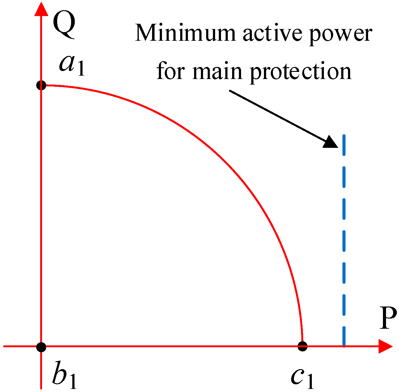
If the critical clearing time is less than the operation time of main protection, the power feasible region does not exist. Adjusting only the active and reactive power of VSC also cannot avoid DC overvoltage. Therefore, the command value of the dispatch center should be adjusted to the reference value of the active power of VSC to avoid DC overvoltage at the moment of fault. Since the DC voltage does not exceed the limit, the power feasible region only needs to satisfy the upper boundary of the VSC. As shown in Figure 6, the line a1b1, the line b1c1, and the curve a1c1 are the boundary of the power feasible region, adjusting the active and reactive power of VSC on the boundary of the power feasible region, and changing the command value of the dispatch center to the active power of VSC. For the straight line a1b1, let the active power in (10) be 0. The combination of active and reactive power of VSC on the straight line a1b1 that maximizes the PCC voltage is obtained as:
P ref 4 = 0 Q ref 4 = U g 2 X f R f 2
For the straight line b1c1, let the reactive power in (10) be 0; the combination of active and reactive power of VSC that maximizes the PCC voltage on the straight line b1c1 can be obtained with the same expression as (17). For curve a1c1, the combination of active and reactive power of VSC that maximizes the PCC voltage on curve a1c1 can be obtained by using the Lagrange multiplier method by associating (2) and (10), and the expression is the same as (18). Different boundaries have different effects on the maximum support of PCC voltage. Substituting the active and reactive power combinations of (17), (18), and (19) into (10), respectively, the one combination P max 2 , Q max 2 that maximizes the PCC can be selected. The maximum voltage support point P max 2 , Q max 2 that avoids the DC overvoltage and the AC overcurrent of the charging station is obtained. In addition, the fault duration of the distribution network is in the hundreds of milliseconds, which is short compared to the topology change and load fluctuations. Therefore, the changes in load and topology are usually ignored in the fault ride-through control of the CS.

4. Control Programs

The control method of voltage support for the CS considering the limitation of DC voltage is shown in Figure 7. The calculation link of the reference value of active power and reactive power for VSC is added, and the switching link of the reference value in the power distribution controller is added. After the grid fault, the PCC voltage amplitude of the CS is collected, and the critical clearing time and the operation time of the main protection are compared according to (6). When the critical clearing time is greater than the operation time of main protection, the outer control of VSC is transformed into active power control and reactive power control, and the reference value is determined by P max 1 , Q max 1 . When the amplitude of PCC voltage does not return to normal at the moment that main protection should operate, the command value of the dispatch center is changed P max 1 , and the active power control is switched back to the voltage control for VSC. When the critical clearing time is less than the operation time of the main protection, the voltage control of VSC is maintained. The reference value of reactive power is determined by Q max 2 , and the command value of the dispatch center is changed to P max 2 . Since the discharge power of the battery is adjusted at the beginning of the grid fault, the power is balanced on both sides of the DC capacitor in the CS. Even if the main protection refuses to operate, the DC voltage cannot exceed the limitation. In addition, only the control reference value is changed in the proposed method. The double closed-loop control is maintained in VSC, and the constant power control is maintained in DAB. The stability of the controller is maintained.
The maximum support of the PCC voltage is realized while avoiding the DC overvoltage based on the relationship between the critical clearing time and the operation time of the main protection. When the critical clearing time is greater than the operation time of the main protection, the proposed voltage support control method can reliably avoid DC overvoltage before the operation time of the main protection and at the same time maximize the support of the PCC voltage. If the CS maintains the normal operation control during the fault, although the DC overvoltage is avoided, the PCC voltage support is limited due to the none of reactive power being emitted by the CS. If the CS follows the fault ride-through method of new energy, the reactive current is output according to the PCC voltage and the active current is limited, which may lead the DC voltage to exceed the limitation before the main protection operates, and the PCC voltage support is poor. When the main protection refuses to operate, if the CS maintains the normal operation control or the fault ride-through control of the new energy, the CS still faces the risk of DC overvoltage; the voltage support control method proposed in this paper can ensure the safety of the DC voltage of the CS and maximize the PCC voltage support due to the elimination of the unbalanced power during the main protection refusal. When the critical clearing time is less than the operation time of main protection, the voltage support control method can reliably avoid DC overvoltage due to the elimination of unbalanced power at the moment of fault; if the CS maintains the normal operation control or the fault ride-through control of the new energy, the CS cannot avoid DC overvoltage and the PCC voltage is poorly supported. In this case, since the unbalanced power has been eliminated at the moment of the fault, even if the main protection refuses to operate, the DC overvoltage can always be avoided.

5. Case Studies

The simulation model shown in Figure 1 is built in 2020b MATLAB/Simulink to verify the effectiveness of the control method of voltage support for the CS. A total of four EVs are in the CS. The CS is connected to the grid through a 0.380/10 kV transformer, and the grid line resistance and inductance converted to the low-voltage side is 0.25 + j0.49 Ω. The reference of DC voltage is 800 V. The voltage control parameters of VSC are k p = 2, k i = 50. The DAB parameters are k vp = 0.0005, k vi = 20, L r = 20 × 10−6  H , f s = 10,000 Hz, n = 800/420. The maximum allowable VSC current is 1.2 p.u and the limitation of DC voltage is 1.2 p.u. The main protection is set to operate 0.1 s after the grid fault, and the backup protection is set to operate 0.6 s after the main protection refuses to operate. Before grid fault, the active power of the CS is set to 1 p.u and the reactive power is set to 0. To verify the insecurity of normal operation control of CS under the fault, the inapplicability of new energy fault ride-through control methods for CS, and the effectiveness of the proposed method, three comparison groups are set up. Method 1 is the control method to maintain the voltage control for the CS, and the reference value of reactive power is set to 0; Method 2 refers to the new energy fault ride-through requirements [22], where voltage control is maintained and the reference of q-axis current is given by I q * = 2 0.9 U f U N I N ; Method 3 is the method of this paper. The simulation model and parameters are based on real-world configurations provided by the State Grid Chongqing Electric Power Company, as part of the collaborative research project funding this work. All parameters are validated against practical charging station operations to ensure realism.

5.1. Case 1: When Critical Clearing Time Is Greater than the Operation Time of Main Protection and the Main Protection Operates

The PCC voltage drops to 0.65 p.u under the grid fault, as shown in Figure 8a. According to (6), the critical clearing time is 112 ms, which exceeds the operating time of the main protection. Voltage control is switched to active power control for VSC under Method 3; the reference values of active and reactive power are 0.75 p.u and 0.21 p.u, respectively. The PCC voltage, DC voltage, active power of VSC, reactive power of VSC, and transmission power of DAB under three methods are obtained by simulations, as shown in Figure 8.
As shown in Figure 8b, the DC voltage under Method 1 and Method 3 does not exceed 1.2 p.u during the fault, while the DC voltage under Method 2 exceeds 1.2 p.u about 50 ms after the fault occurs. As shown in Figure 8c,d, the active and reactive power values under Method 1 are 0.78 p.u and 0 during the fault, respectively. Reactive power control of VSC is prioritized under Method 2; 0.33 p.u reactive power and 0.71 p.u active power are output according to the degree of PCC voltage drop. An active power of 0.75 p.u and a reactive power of 0.21 p.u are output under Method 3. As shown in Figure 8, the support effect of PCC voltage is limited during the fault period because the CS only outputs active power under Method 1, and the PCC voltage is raised to 0.67 p.u. Under method 2, the PCC voltage is raised to 0.71 p.u due to the priority of reactive power control at the CS. The CS follows the maximum voltage control method under Method 3, and the PCC voltage is raised to 0.75 p.u, which is a significant improvement over the voltage support effect under Method 1 and Method 2. Improvements to the VSC control under Method 3 do not affect the discharge of EVs in the CS during the fault. The method proposed in this paper can better support the PCC voltage while avoiding DC overvoltage.

5.2. Case 2: Critical Clearing Time Is Greater than the Operation Time of the Main Protection and the Main Protection Refuses to Operate

The fault conditions are the same as Case 1, but the main protection refuses to operate at 0.4 s and the fault is removed by the backup protection at 1 s. The control reference values for Method 2 and Method 3 are the same as Case 1. The voltage control of VSC is resumed when the fault is detected as not being removed at 0.4 s under Method 3; the command value of the dispatch center is adjusted to 0.75 p.u at the same time. The PCC voltage, DC voltage, active power of VSC, reactive power of VSC, and transmission power of DAB under three methods are obtained by simulations, as shown in Figure 9.
As shown in Figure 9b, the DC voltage under Method 1 exceeds 1.2 p.u 30 ms after the main protection refuses to operate. The DC voltage under Method 2 exceeds 1.2 p.u before the main protection refuses to operate. The command value of the dispatch center is adjusted at 0.4 s under Method 3, so that the active power of VSC is balanced with the transmission power of DAB again, and the DC voltage is gradually restored to the reference value after 0.4 s; the DC overvoltage is avoided. As shown in Figure 9c,d, the active and reactive power values of VSC are 0.78 p.u and 0 under Method 1, respectively. The active and reactive power values of VSC under Method 2 are 0.71 p.u and 0.33 p.u, respectively. The active and reactive power values of VSC under Method 3 are 0.75 p.u and 0.21 p.u, respectively. As shown in Figure 9a, the support effect of PCC voltage is limited during the fault under Method 1 because the CS only outputs active power, and the PCC voltage is raised to 0.68 p.u. The PCC voltage support is not effective under Method 2, because the VSC does not follow the control point of maximum voltage, and the PCC voltage is raised to 0.71 p.u. The CS under Method 3 follows the control point of maximum voltage, and the PCC voltage is raised to 0.75 p.u, which is a significant improvement over Method 1 and Method 2 voltage support effect. As shown in Figure 9e, the entire fault process in Method 1 and Method 2 does not regulate the transmission power of DAB, and the DC voltage in Figure 9b exceeds 1.2 p.u. The transmission power of DAB follows the command value of the dispatch center being adjusted to 0.75 p.u under Method 3 when the main protection refuses to operate; DC overvoltage is avoided in Figure 9b. The VSC is not operated at the support point of maximum voltage and DC overvoltage is not avoided under Method 1 and Method 2. Even in the case that the main protection refuses to operate, the DC overvoltage is avoided and PCC voltage is better supported under Method 3.

5.3. Case 3: The Critical Clearing Time Is Less than the Operation Time of the Main Protection

The PCC voltage drops to 0.5 p.u after the grid fault. From (6), the critical clearing time is 61 ms less than the operation time of the main protection. The voltage control and reactive power control of VSC are maintained under Method 3. The reference value of reactive power is 0.53 p.u and the command value of the dispatch center is 0.27 p.u. The PCC voltage, DC voltage, active power of VSC, reactive power of VSC, and transmission power of DAB under three methods are obtained by simulations, as shown in Figure 10.
As shown in Figure 10b, the DC voltage under Method 1 exceeds 1.2 p.u 80 ms after grid fault. The DC voltage under Method 2 exceeds 1.2 p.u 20 ms after the grid fault; at the moment of fault removal, the DC voltage has reached nearly 1.3 p.u, and the safety of the CS is seriously threatened. The DC voltage under Method 3 is essentially maintained at 1.0 p.u after the fault, DC overvoltage is avoided. As shown in Figure 10c,d, the active and reactive power values of the VSC under Method 1 are 0.6 p.u and 0, respectively. The active and reactive power values of VSC under Method 2 are 0.45 p.u and 0.4 p.u, respectively. The active and reactive power values of VSC under Method 3 are 0.27 p.u and 0.53 p.u, respectively. As shown in Figure 10a, the support effect of PCC voltage is limited during the fault under Method 1 because the CS only outputs active power, and the PCC voltage is raised to 0.53 p.u. The PCC voltage support is not effective under Method 2 because the VSC does not follow the control point of maximum voltage, and the PCC voltage is raised to 0.58 p.u. The CS under Method 3 follows the control point of maximum voltage, and the PCC voltage is raised to 0.63 p.u, which is a significant improvement over the voltage support effect of Method 1 and Method 2. As shown in Figure 10e, the entire fault process under Method 1 and Method 2 does not regulate the transmission power of DAB. The command value of the dispatch center under Method 3 is changed at the moment of the grid fault, unbalanced power is eliminated, and DC overvoltage is avoided. The improvement of VSC and DAB control by Method 3 does not affect the EV discharge during the fault. Therefore, the proposed method avoids DC overvoltage while enhancing PCC voltage support.

5.4. Case 4: Critical Clearing Time Is Less than the Operation Time of the Main Protection and the Main Protection Refuses to Operate

The fault conditions are the same as Case 3, but the main protection refuses to operate at 0.4 s and the fault is removed by the backup protection at 1 s. The control reference values for Method 2 and Method 3 are the same as Case 3. The voltage control and reactive power control of VSC are maintained under Method 3. The reference value of reactive power is 0.53 p.u and the command value of the dispatch center is 0.27 p.u. The PCC voltage, DC voltage, active power of VSC, reactive power of VSC, and transmission power of DAB under three methods are obtained by simulations, as shown in Figure 11.
As shown in Figure 11b, the DC voltage under Method 1 exceeds 1.2 p.u 80 ms after grid fault. The DC voltage under Method 2 exceeds 1.2 p.u 20 ms after the grid fault; at the moment of fault removal, the DC voltage has reached nearly 1.4 p.u, and the safety of the CS is seriously threatened. The DC voltage under Method 3 is essentially maintained at 1.0 p.u after the fault, and DC overvoltage is avoided. As shown in Figure 11c,d, the active and reactive power values of the VSC under Method 1 are 0.6 p.u and 0, respectively. The active and reactive power values of VSC under Method 2 are 0.45 p.u and 0.4 p.u, respectively. The active and reactive power values of VSC under Method 3 are 0.27 p.u and 0.53 p.u, respectively. As shown in Figure 11a, the support effect of PCC voltage is limited during the fault under Method 1 because the CS only outputs active power, and the PCC voltage is raised to 0.53 p.u. The PCC voltage support is not effective under Method 2 because the VSC does not follow the control point of maximum voltage, and the PCC voltage is raised to 0.58 p.u. The CS under Method 3 follows the control point of maximum voltage, and the PCC voltage is raised to 0.63 p.u, which is a significant improvement over the voltage support effect of Method 1 and Method 2. As shown in Figure 11e, the entire fault process under Method 1 and Method 2 does not regulate the transmission power of DAB. The command value of the dispatch center under Method 3 is changed at the moment of the grid fault, unbalanced power is eliminated, and DC overvoltage is avoided. Under Method 1 and Method 2, the CS is not operated at the support point of maximum voltage and DC overvoltage is not avoided. Under Method 3, even in the case that the main protection refuses to operate, the DC overvoltage is avoided and PCC voltage is better supported.

6. Conclusions

Due to the lack of a control method of PCC voltage support for CS under V2G mode, a power feasible region of CS that ensures the safety of the DC voltage and the VSC current is established. A calculation method of the critical clearing time of fault to avoid DC overvoltage is proposed. The characteristic that the control point of maximum voltage support lies at the boundary of the power feasible region is revealed, the critical clearing time of fault and the operation time of main protection are compared, and a control method of PCC voltage support for CS considering the limitation of the DC voltage and VSC current is proposed. Theoretical analysis and simulation show that when the critical clearing time is greater than the operation time of main protection, the proposed method can avoid DC overvoltage and maximize the support effect of PCC voltage while controlling only the VSC. When the critical clearing time is less than the operation time of main protection or when the main protection refuses to operate, the DC overvoltage is avoided and the PCC voltage is supported to the max through the coordinated control of both VSC and DAB in the proposed method. The proposed method enables maximum voltage support for the CS during the fault without additional energy storage devices and avoids the impact of unloading. The control method of voltage support for CS can be applied to an individual EV and can also be considered as a reference for vehicle–grid interaction of CS under grid fault.
Additionally, double-frequency active power causes a fluctuation rise in DC voltage under asymmetrical fault, which makes the proposed method inapplicable. The power feasible region, the critical clearing time, and the control reference values need to be further investigated.

Author Contributions

Methodology, J.O.; Software, A.L.; Formal analysis, A.L.; Writing—original draft, J.O., A.L. and Y.D.; Writing—review and editing, F.H.; Supervision, F.H.; Project administration, J.O.; Funding acquisition, J.O. All authors have read and agreed to the published version of the manuscript.

Funding

This research was funded by [State Grid Chongqing Electric Power Company Key Science and Technology Project Funding] under grant [52202322001M].

Institutional Review Board Statement

Not applicable.

Informed Consent Statement

Not applicable.

Data Availability Statement

The original contributions presented in the study are included in the article; further inquiries can be directed to the corresponding author.

Conflicts of Interest

The authors declare no conflicts of interest.

Abbreviations

The following abbreviations are used in this manuscript:
CScharging station
V2Gvehicle-to-grid
PCCpoint of common coupling
EVelectric vehicle
SOCstate of charge

References

  1. Yao, L.; Li, Q.; Yang, J.; Zhang, Y. Comprehensive Reactive Power Optimization of Power Distribution and Consumption System with Support of Electric Vehicle Charging and Discharging. Autom. Electr. Power Syst. 2022, 46, 39–47. [Google Scholar]
  2. Zhu, L.; Huang, H.; Gao, S.; He, Y.; Bian, Y. Research on Optimal Load Allocation of Electric Vehicle Considering Wind Power Consumption. Proc. CSEE 2021, 41, 194–203. [Google Scholar]
  3. Mahfouz, M.; Iravani, M.R.M. Grid-Integration of Battery-Enabled DC Fast Charging Station for Electric Vehicles. IEEE Trans. Energy Convers. 2020, 35, 375–385. [Google Scholar] [CrossRef]
  4. Liu, L.; Lin, G.; Jiao, S.; An, B.; Li, Y.; Wang, Z.; Wang, S. Virtual DC Generator Control Strategy and its Dynamic Analysis of DC Charging Station Microgrid. Power Syst. Prot. Control 2020, 48, 28–35. [Google Scholar]
  5. Franzese, P.; Patel, D.D.; Mohamed, A.A.S.; Iannuzzi, D.; Fahimi, B.; Risso, M. Fast DC Charging Infrastructures for Electric Vehicles: Overview of Technologies, Standards, and Challenges. IEEE Trans. Transp. Electrif. 2023, 9, 3780–3800. [Google Scholar] [CrossRef]
  6. Deng, J.; Cui, H.; Chao, P.; Xia, N.; Li, M.; Li, W. Efficient Parallel Identification Method of DFIG Controller Parameters Based On Dominant Response Characteristic Analysis. Electr. Power Autom. Equip. 2025, 4, 43–50. [Google Scholar]
  7. Guan, L.; Yao, J. Dynamic Coupling and Cooperative Control for Multi-Paralleled Doubly Fed Induction Generator Wind Farms During Symmetrical Low Voltage Ride-Through in a Weak Grid. Prot. Control Mod. Power Syst. 2024, 9, 112–125. [Google Scholar] [CrossRef]
  8. Naderi, S.B.; Negnevitsky, M.; Muttaqi, K.M. A Modified DC Chopper for Limiting the Fault Current and Controlling the DC-Link Voltage to Enhance Fault Ride-Through Capability of Doubly-Fed Induction-Generator-Based Wind Turbine. IEEE Trans. Ind. Appl. 2019, 55, 2021–2032. [Google Scholar] [CrossRef]
  9. Li, B.; Zheng, D.; Li, B.; Jiao, X.; Hong, Q.; Ji, L. Analysis of Low Voltage Ride-Through Capability and Optimal Control Strategy of Doubly-Fed Wind Farms Under Symmetrical Fault. Prot. Control Mod. Power Syst. 2023, 8, 36. [Google Scholar] [CrossRef]
  10. Qin, Y.; Wang, H.; Deng, Z.; Zhang, J.; Yang, R.; Cai, X. Control of Inertia-Synchronization Controlled Wind Turbine Generators Under Symmetrical Grid Faults. IEEE Trans. Energy Convers. 2023, 38, 1085–1096. [Google Scholar] [CrossRef]
  11. Shabestary, M.M.; Mohamed, Y.A.I. Advanced Voltage Support and Active Power Flow Control In Grid-Connected Converters under Unbalanced Conditions. IEEE Trans. Power Electron. 2018, 33, 1855–1864. [Google Scholar] [CrossRef]
  12. Camacho, A.; Castilla, M.; Miret, J.; de Vicuña, L.G.; Miguel Andrés, G.L. Control Strategy for Distribution Generation Inverters to Maximize the Voltage Support in the Lowest Phase During Voltage Sags. IEEE Trans. Ind. Electron. 2018, 65, 2346–2355. [Google Scholar] [CrossRef]
  13. Gui, Y.; Nainar, K.; Bendtsen, J.D.; Diewald, N.; Iov, F.; Yang, Y. Voltage Support With PV Inverters in Low-Voltage Distribution Networks: An Overview. IEEE J. Emerg. Sel. Top. Power Electron. 2024, 12, 1503–1522. [Google Scholar] [CrossRef]
  14. Ghahderijani, M.M.; Camacho, A.; Moreira, C.; Castilla, M.; Vicuña, L.G. Imbalance-Voltage Mitigation in An Inverter-Based Distributed Generation System Using A Minimum Current-Based Control Strategy. IEEE Trans. Power Deliv. 2020, 35, 1399–1409. [Google Scholar] [CrossRef]
  15. Camacho, A.; Castilla, M.; Miret, J.; Vicuña, L.G.; Guzman, R. Positive and Negative Sequence Control Strategies to Maximize the Voltage Support in Resistive-Inductive Grids during Grid Faults. IEEE Trans. Power Electron. 2018, 33, 5362–5373. [Google Scholar] [CrossRef]
  16. Chen, J.; Ouyang, J.; Yu, J.; Chen, Y.; Li, A. DC Voltage Cooperative Control Method for VSC-HVDC Under Receiving-End Grid Fault. IEEE Trans. Power Deliv. 2024, 39, 1659–1673. [Google Scholar] [CrossRef]
  17. Yang, R.; Zhang, C.; Cai, X.; Shi, G.; Li, J.; Miao, Y.; Cao, L. Voltage Source Control and Fault Ride-through of VSC-HVDC Systems With Offshore Wind Farm Integration. Proc. CSEE 2022, 42, 4823–4835. [Google Scholar]
  18. Pei, Z.; Wang, X.; Kang, L. Review on Control Strategies for Electric Vehicles Participating in Ancillary Services of Power Grid. Autom. Electr. Power Syst. 2023, 47, 17–32. [Google Scholar]
  19. Sun, F.; Diao, R.; Zhou, B.; Lan, T.; Mao, T.; Su, S. Prediction-Based EV-PV Coordination Strategy for Charging Stations Using Reinforcement Learning. IEEE Trans. Ind. Appl. 2024, 60, 910–919. [Google Scholar]
  20. Department of Mathematics, Tongji University. Higher Mathematics; Higher Education Press: Beijing, China, 2014. [Google Scholar]
  21. Sahoo, B.; Samantaray, S.R.; Bhalja, B.R. An Effective Zone-3 Supervision of Distance Relay for Enhancing Wide Area Back-Up Protection of Transmission System. IEEE Trans. Power Deliv. 2021, 36, 3204–3213. [Google Scholar] [CrossRef]
  22. GB/T 37408-2019; Technical Requirements for Grid-Connected Inverters for Photovoltaic Power Generation. State Administration for Market Regulation, and China National Standardization Administration: Beijing, China, 2019.
Figure 1. Topology of CS.
Sustainability 17 03713 g001
Figure 2. Constant power control of DAB.
Sustainability 17 03713 g002
Figure 3. Power feasible region for the CS.
Sustainability 17 03713 g003
Figure 4. Equivalent access circuit diagram of CS under a grid fault. Red arrow represents the grid fault.
Sustainability 17 03713 g004
Figure 5. When the critical clearing time is greater than the operation time of the main protection.
Sustainability 17 03713 g005
Figure 6. When the critical clearing time is less than the operation time of the main protection.
Sustainability 17 03713 g006
Figure 7. Block diagram of voltage support control.
Sustainability 17 03713 g007
Figure 8. Simulation results for Case 1. (a) PCC voltage; (b) DC voltage; (c) active power of VSC; (d) reactive power of VSC; (e) transmission power of DAB.
Sustainability 17 03713 g008
Figure 9. Simulation results for Case 2. (a) PCC voltage; (b) DC voltage; (c) active power of VSC; (d) reactive power of VSC; (e) transmission power of DAB.
Sustainability 17 03713 g009
Figure 10. Simulation results for Case 3. (a) PCC voltage; (b) DC voltage; (c) active power of VSC; (d) reactive power of VSC; (e) transmission power of DAB.
Sustainability 17 03713 g010
Figure 11. Simulation results for Case 4. (a) PCC voltage; (b) DC voltage; (c) active power of VSC; (d) reactive power of VSC; (e) transmission power of DAB.
Sustainability 17 03713 g011
Disclaimer/Publisher’s Note: The statements, opinions and data contained in all publications are solely those of the individual author(s) and contributor(s) and not of MDPI and/or the editor(s). MDPI and/or the editor(s) disclaim responsibility for any injury to people or property resulting from any ideas, methods, instructions or products referred to in the content.

