
The Strength, Permeability, and Microstructure of Cement–Bentonite Cut-Off Walls Enhanced by Polypropylene Fiber

Abstract
1. Introduction
2. Materials and Methods
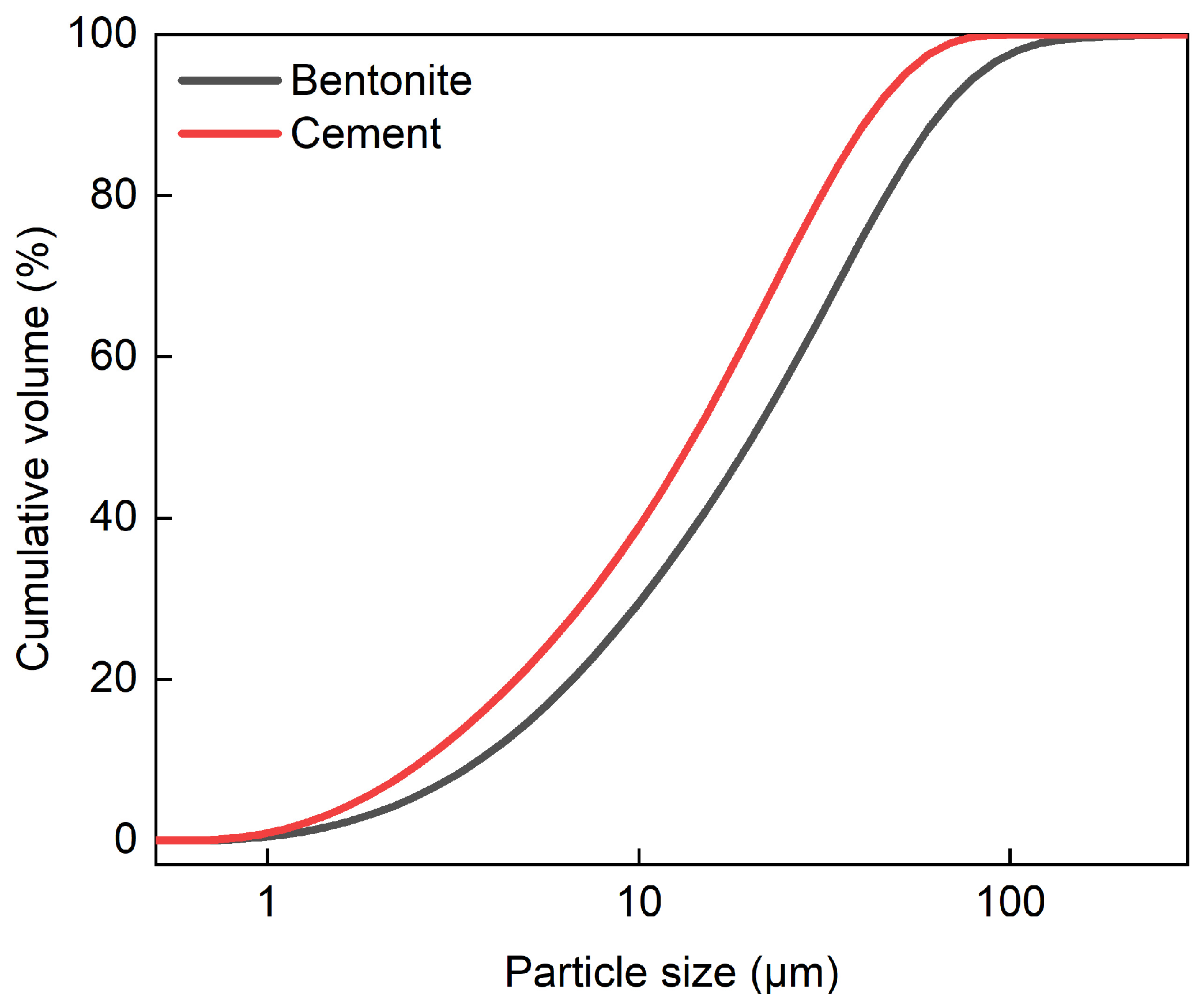
2.1. Materials
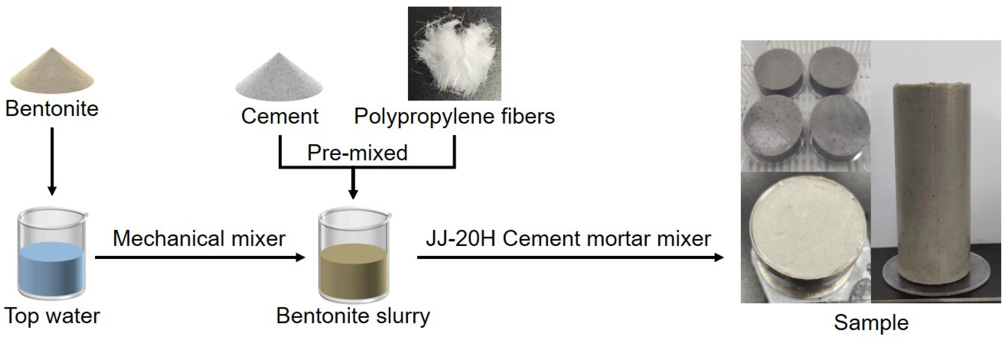
2.2. Sample Mixing Proportion Design and Preparation
2.3. Methods
2.3.1. Unconfined Compressive Strength Test
2.3.2. Direct Shear Test
2.3.3. Falling Head Permeability Test
2.3.4. Microstructural Analysis
3. Results and Discussion
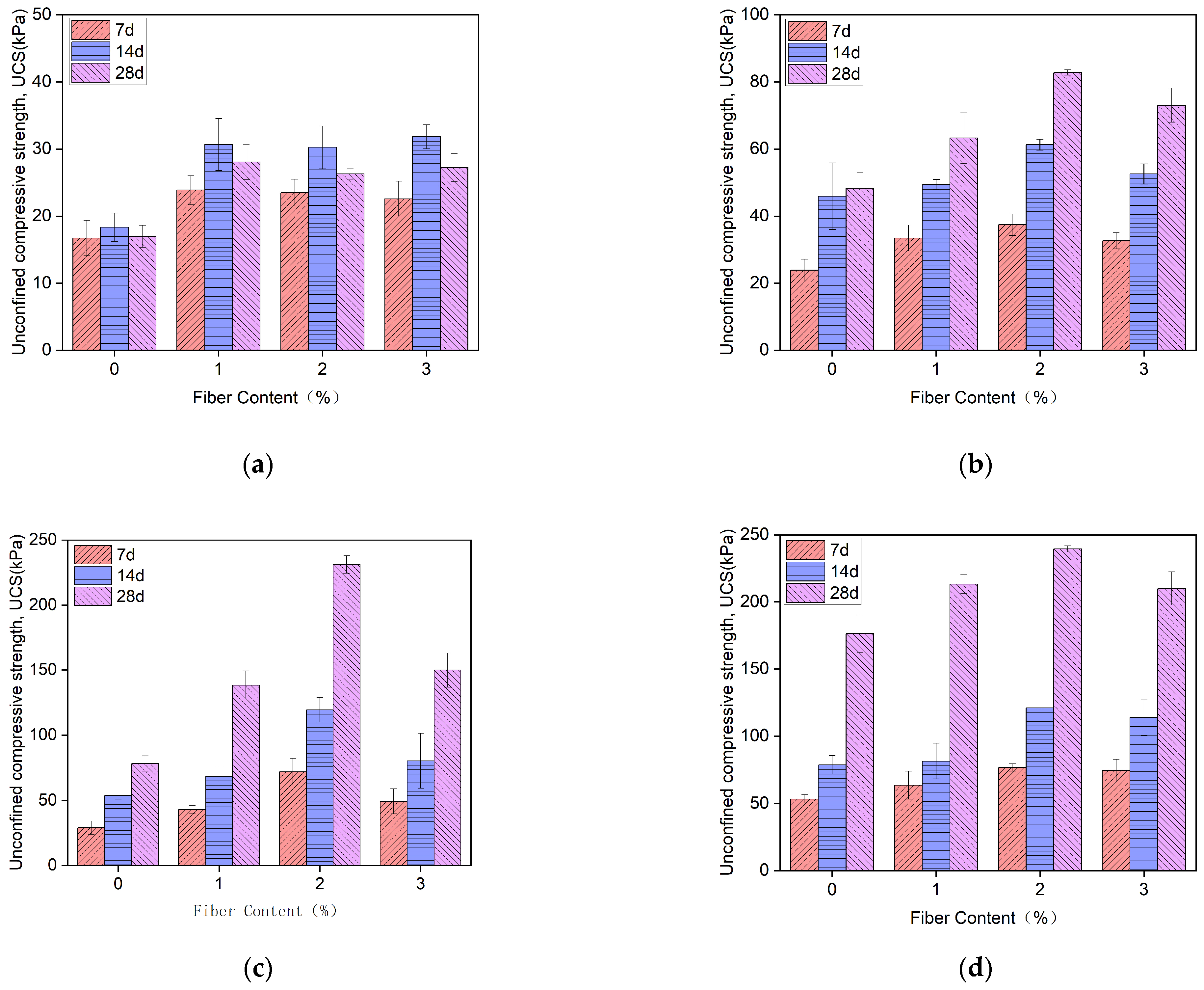
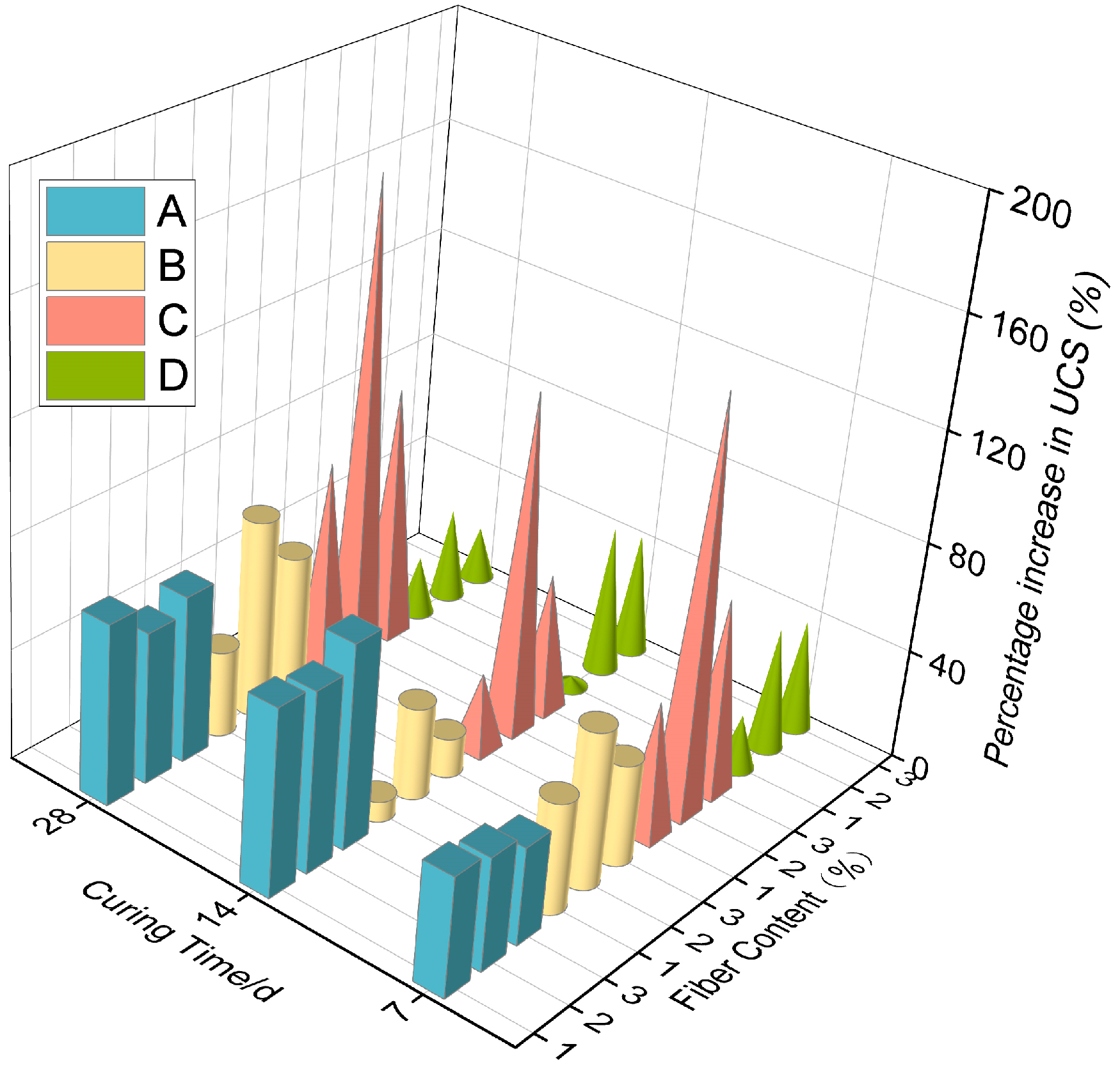
3.1. Unconfined Compressive Strength (UCS)
3.2. Shear Strength
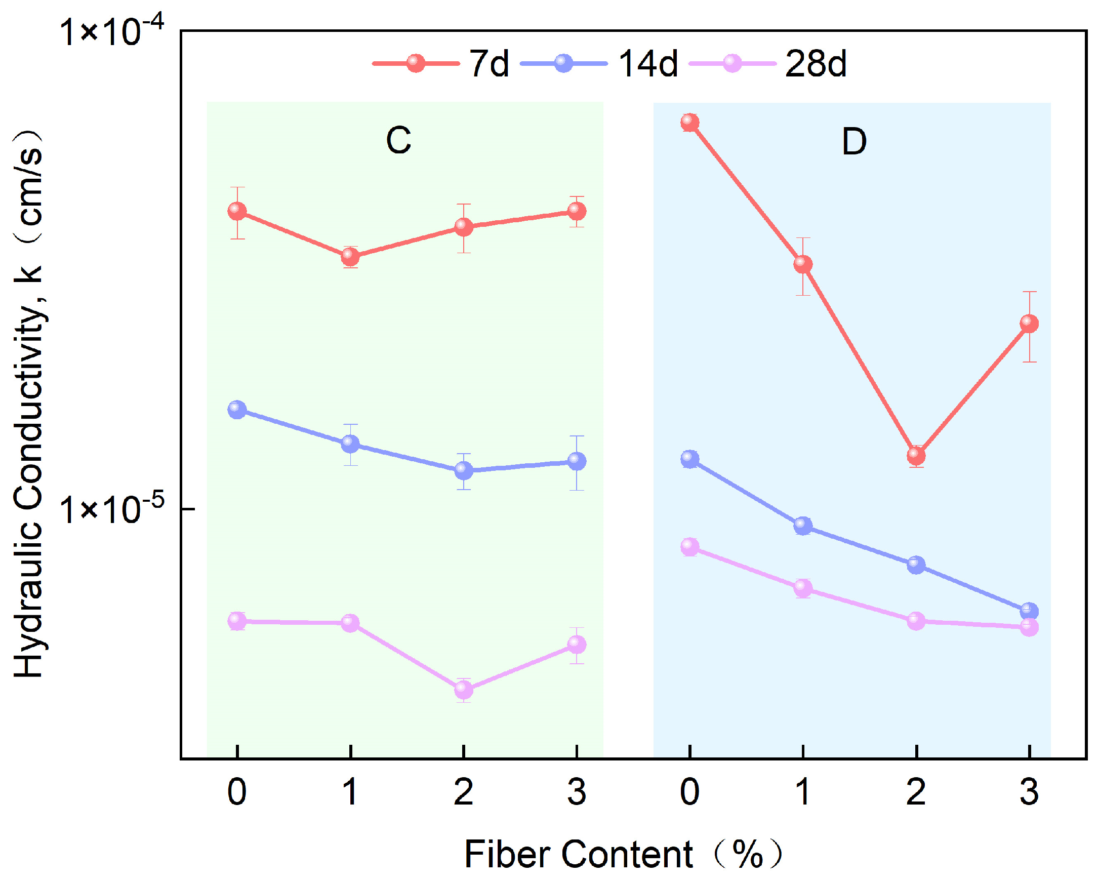
3.3. Hydraulic Conductivity (k)
3.4. Microstructural
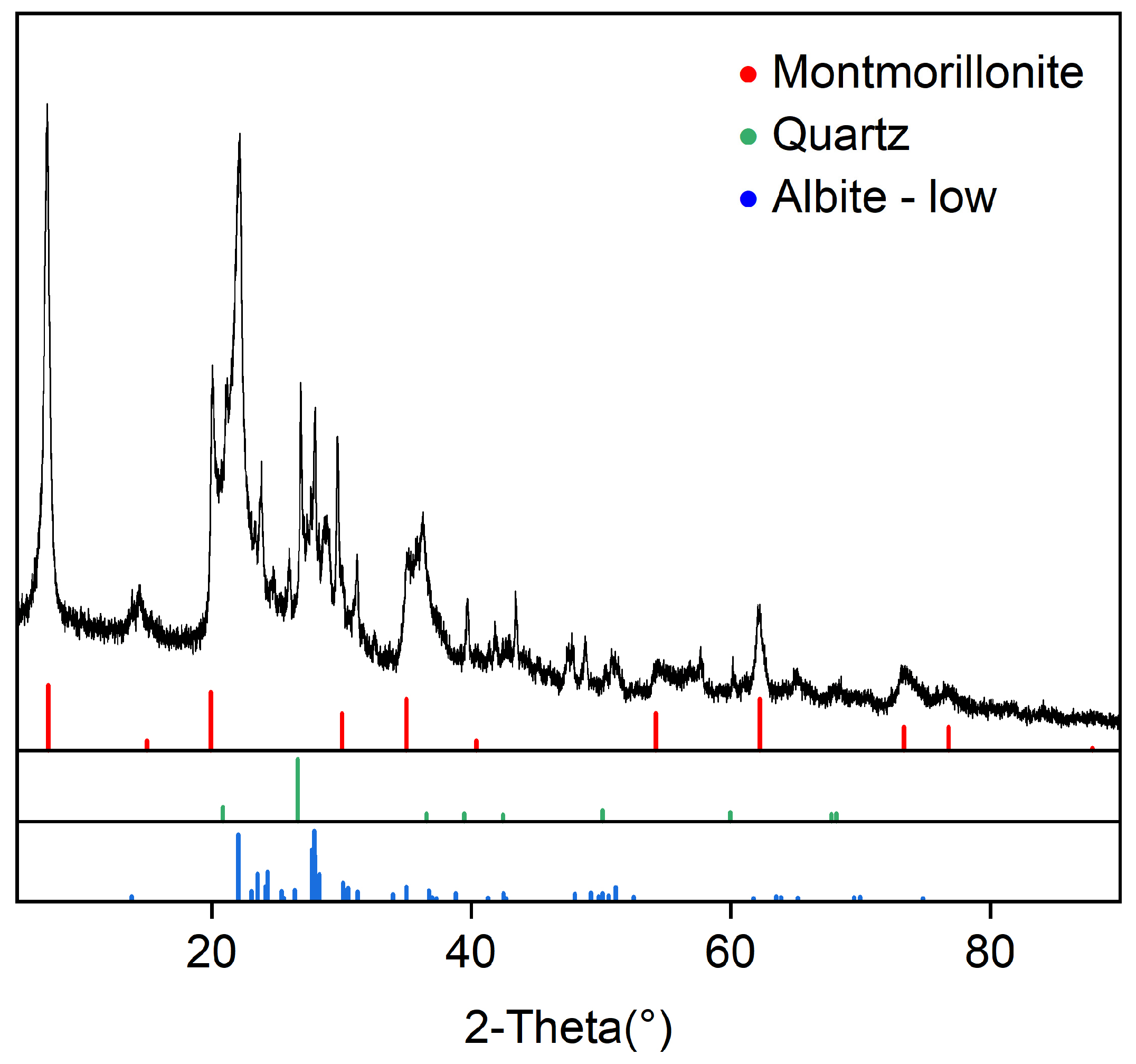
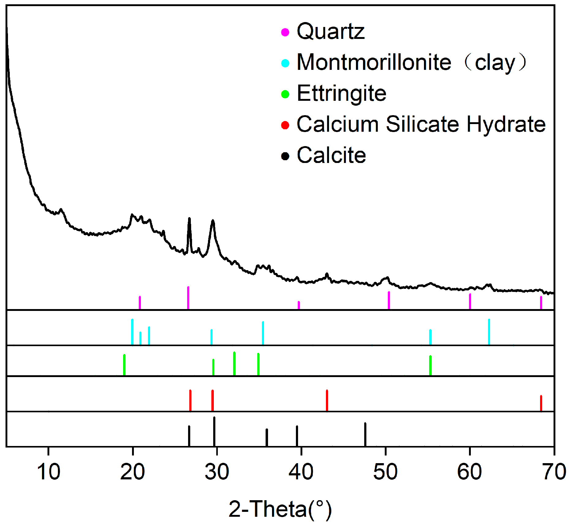
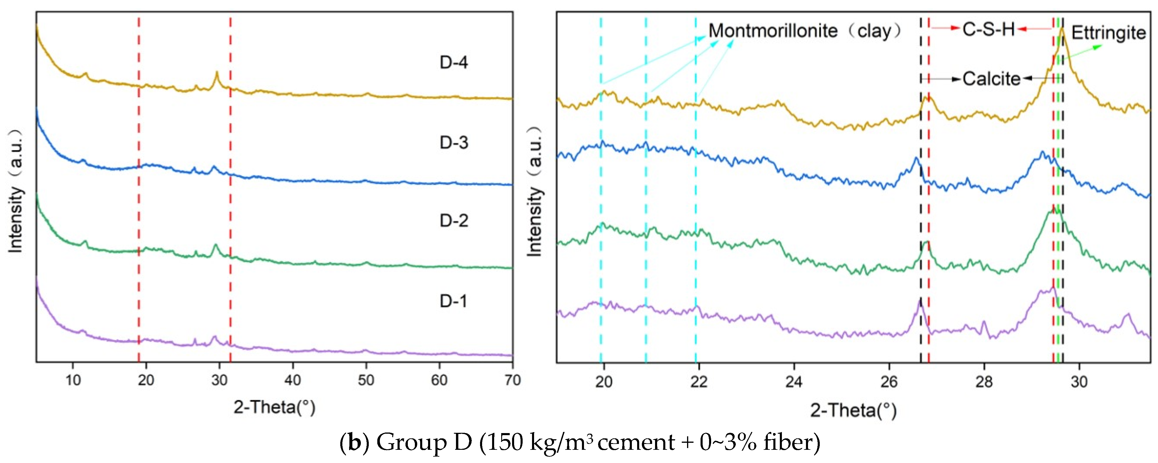
3.4.1. XRD Analysis
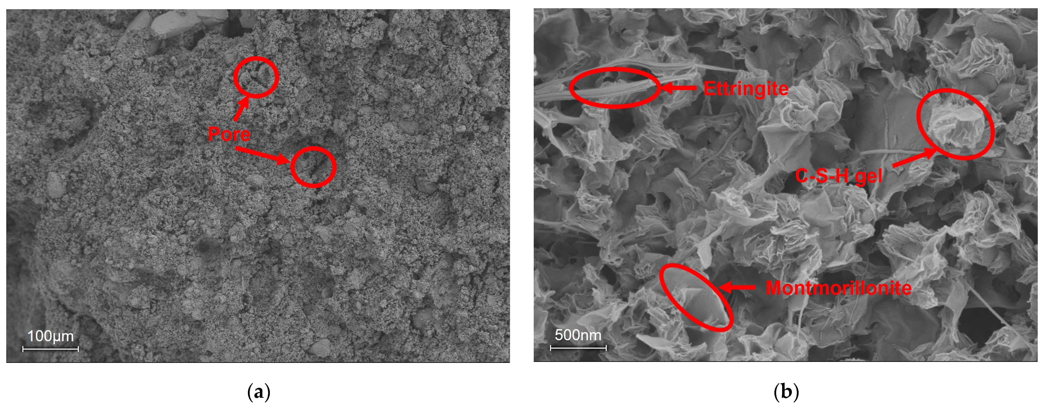
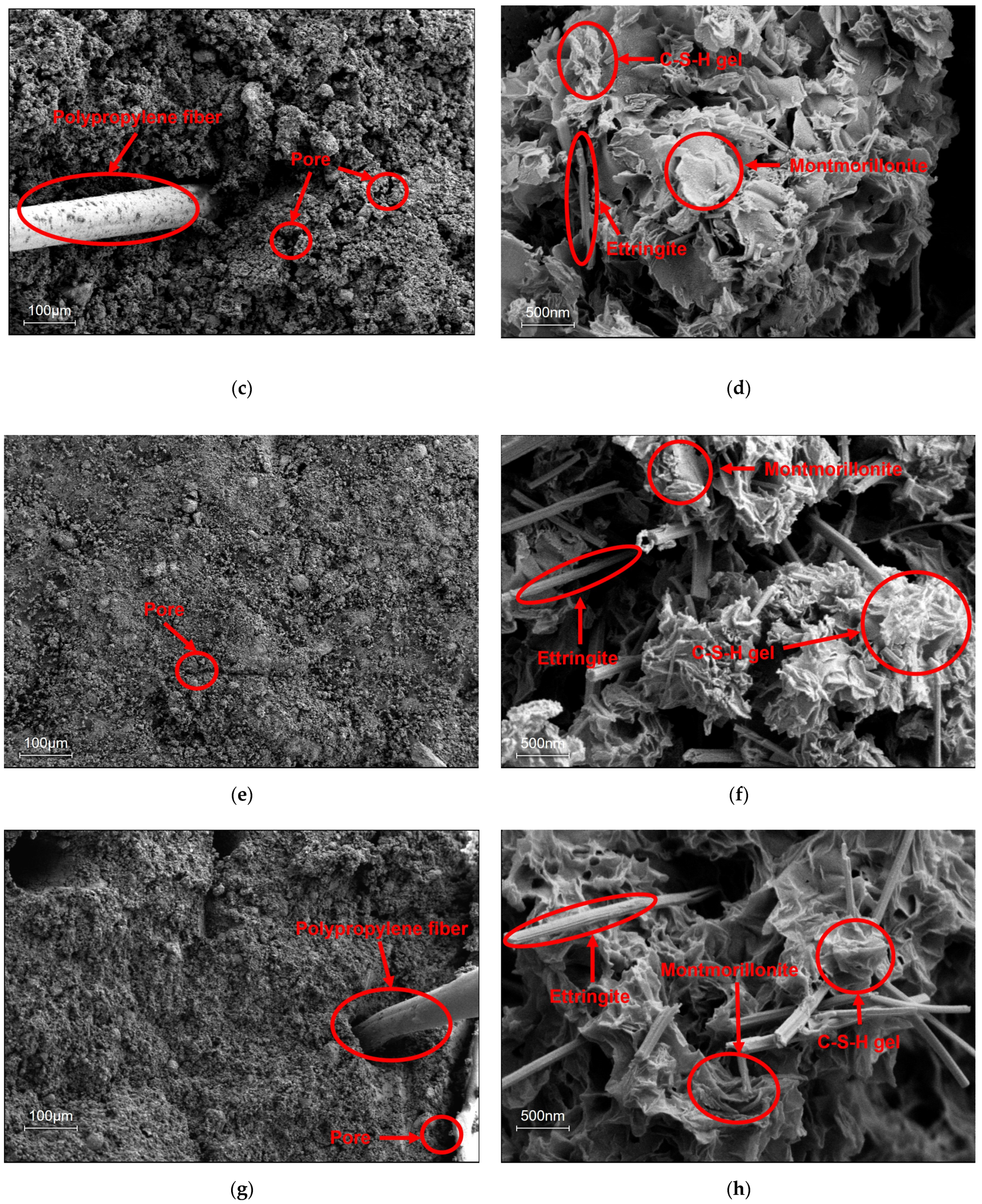
3.4.2. Scanning Electron Microscopy (SEM)
3.5. Economic and Environmental Evaluation
4. Conclusions
Author Contributions
Funding
Institutional Review Board Statement
Informed Consent Statement
Data Availability Statement
Conflicts of Interest
References
- He, K.; Deng, Y.; Cao, Z.; Zhang, X. Engineering Performance and Microscale Structure of Activated High Titanium Slag-Soil-Cement-Bentonite (HTS-SCB) Slurry Backfill. Constr. Build. Mater. 2023, 373, 130776. [Google Scholar] [CrossRef]
- Ting, M.Z.Y.; Yi, Y. Influence of Short-Term Binder-Bentonite Interactions on Workability of Sand-Bentonite-Binder Mixture for Seepage Cut-off Wall. Constr. Build. Mater. 2023, 383, 131260. [Google Scholar] [CrossRef]
- Huang, X.; Li, J.S.; Xue, Q.; Chen, Z.; Du, Y.J.; Wan, Y.; Liu, L.; Poon, C.S. Use of Self-Hardening Slurry for Trench Cutoff Wall: A Review. Constr. Build. Mater. 2021, 286, 122959. [Google Scholar] [CrossRef]
- Ryan, C.; Ruffing, D.; Evans, J.C. Soil Bentonite Slurry Trench Cutoff Walls: History, Design, and Construction Practices. In Proceedings of the Geo-Congress, Charlotte, NC, USA, 20–23 March 2022; Volume 2022, pp. 89–99. [Google Scholar] [CrossRef]
- Joshi, K.; Kechavarzi, C.; Sutherland, K.; Ng, M.Y.A.; Soga, K.; Tedd, P. Laboratory and In Situ Tests for Long-Term Hydraulic Conductivity of a Cement-Bentonite Cutoff Wall. J. Geotech. Geoenviron. Eng. 2010, 136, 562–572. [Google Scholar] [CrossRef]
- He, Y.; Li, S.; Zhang, Z.; Zhu, K.; Wei, H. Journal of Rock Mechanics and Geotechnical Engineering Hydro-Microstructural Behaviors of Zeolite / Active Carbon Amended. J. Rock Mech. Geotech. Eng. 2025, 17, 2590–2602. [Google Scholar] [CrossRef]
- Shu, S.; Lü, Y.; Wu, X.; Liu, H. Ecotoxicology and Environmental Safety Pollution Characteristics and Vertical Cutoff Wall Optimization at an Industrial Contaminated Site in China. Ecotoxicol. Environ. Saf. 2022, 235, 113435. [Google Scholar] [CrossRef]
- Opdyke, S.M.; Evans, J.C. Slag-Cement-Bentonite Slurry Walls. J. Geotech. Geoenviron. Eng. 2005, 131, 673–681. [Google Scholar] [CrossRef]
- Balmer, S.; Kaufhold, S.; Dohrmann, R. Cement-Bentonite-Iron Interactions on Small Scale Tests for Testing Performance of Bentonites as a Barrier in High-Level Radioactive Waste Repository Concepts. Appl. Clay Sci. 2017, 135, 427–436. [Google Scholar] [CrossRef]
- Cundy, A.B.; Bardos, R.P.; Church, A.; Puschenreiter, M.; Friesl-hanl, W.; Müller, I. Developing Principles of Sustainability and Stakeholder Engagement for “ Gentle ” Remediation Approaches: The European Context. J. Environ. Manag. 2013, 129, 283–291. [Google Scholar] [CrossRef]
- Fang, Y.; Ding, N.; Li, X.; Wang, S.; Jiao, W. The Influence of the Public’s Prior Knowledge on Their Acceptance of Risk Control Method for Contaminated Sites: A Case Study in China. Alex. Eng. J. 2022, 61, 2787–2797. [Google Scholar] [CrossRef]
- Kuppusamy, S.; Venkateswarlu, K.; Megharaj, M. Chemosphere Risk-Based Remediation of Polluted Sites: A Critical Perspective. Chemosphere 2017, 186, 607–615. [Google Scholar] [CrossRef] [PubMed]
- Garvin, S.L.; Hayles, C.S. Chemical Compatibility of Cement-Bentonite Cut-off Wall Material. Constr. Build. Mater. 1999, 13, 329–341. [Google Scholar] [CrossRef]
- Royal, A.C.D.; Opukumo, A.W.; Qadr, C.S.; Perkins, L.M.; Walenna, M.A. Deformation and Compression Behaviour of a Cement–Bentonite Slurry for Groundwater Control Applications. Geotech. Geol. Eng. 2018, 36, 835–853. [Google Scholar] [CrossRef]
- Flessati, L.; Della Vecchia, G.; Musso, G. Effects of Curing on the Hydro-Mechanical Behaviour of Cement-Bentonite Mixtures for Cut-off Walls. Constr. Build. Mater. 2023, 383, 131392. [Google Scholar] [CrossRef]
- Jefferis, S. Cement-Bentonite Slurry Systems. In Proceedings of the Grouting and Deep Mixing 2012, New Orleans, Louisiana, 15–18 February 2012; pp. 1–24. [Google Scholar] [CrossRef]
- Cao, B.; Xu, J.; Wang, F.; Zhang, Y.; O’connor, D. Vertical Barriers for Land Contamination Containment: A Review. Int. J. Environ. Res. Public Health 2021, 18, 12643. [Google Scholar] [CrossRef]
- Evans, J.C.; Larrahondo, J.M.; Yeboah, N.N.N. Fate of Bentonite in Slag-Cement-Bentonite Slurry Trench Cut-off Walls for Polluted Sites. Environ. Geotech. 2021, 10, 319–331. [Google Scholar] [CrossRef]
- Yamaguchi, T.; Sawaguchi, T.; Tsukada, M.; Hoshino, S.; Tanaka, T. Mineralogical Changes and Associated Decrease in Tritiated Water Diffusivity after Alteration of Cement–Bentonite Interfaces. Clay Miner. 2016, 51, 279–287. [Google Scholar] [CrossRef]
- Carreto, J.M.R.; Caldeira, L.M.M.S.; Neves, E.J.L.M. das Hydromechanical Characterization of Cement-Bentonite Slurries in the Context of Cutoff Wall Applications. J. Mater. Civ. Eng. 2016, 28, 04015093. [Google Scholar] [CrossRef]
- Andrew, R.M. Global CO2 Emissions from Cement Production. Earth Syst. Sci. Data 2018, 10, 195–217. [Google Scholar] [CrossRef]
- Amran, M.; Makul, N.; Fediuk, R.; Lee, Y.H.; Vatin, N.I.; Lee, Y.Y.; Mohammed, K. Global Carbon Recoverability Experiences from the Cement Industry. Case Stud. Constr. Mater. 2022, 17, e01439. [Google Scholar] [CrossRef]
- Zhang, C.Y.; Han, R.; Yu, B.; Wei, Y.M. Accounting Process-Related CO2 Emissions from Global Cement Production under Shared Socioeconomic Pathways. J. Clean. Prod. 2018, 184, 451–465. [Google Scholar] [CrossRef]
- Gao, P.; Zha, W.; Chu, Y.; Yu, Y.; Zhan, B.; Yu, Q.; Xie, F.; Lu, H. Calculation Model for CO2 Emissions of Blended Cement Production. J. Clean. Prod. 2025, 489, 144646. [Google Scholar] [CrossRef]
- Zhou, Y.; Wang, G.H.; Yuan, Y.F. Basic Properties and Engineering Application of Bentonite-Cement-Water Glass Grouting. KSCE J. Civ. Eng. 2020, 24, 2742–2750. [Google Scholar] [CrossRef]
- Wei, Z.; Cui, W.; Miao, R. cheng Experimental Study on Influence of Na-Bentonite on Viscosity of Cement-Bentonite Slurry. Case Stud. Constr. Mater. 2025, 22, e04306. [Google Scholar] [CrossRef]
- Cao, B.; Souza, L.; Wang, F.; Xu, J.; Litina, C.; Al-Tabbaa, A. The First Microcapsule-Based Self-Healing Cement–Bentonite Cut-off Wall Materials. Geotechnique 2023, 73, 105–114. [Google Scholar] [CrossRef]
- Cao, B.; Zhang, Y.; Al-Tabbaa, A. SEBS-Polymer-Modified Slag–Cement–Bentonite for Resilient Slurry Walls. Sustainability 2022, 14, 2093. [Google Scholar] [CrossRef]
- Niu, M.; Li, G.; Wang, Y.; Cao, L.; Han, L.; Li, Q.; Song, Z. Immobilization of Pb2+ and Cr3+ Using Bentonite-Sulfoaluminate Cement Composites. Constr. Build. Mater. 2019, 225, 868–878. [Google Scholar] [CrossRef]
- Cui, Q.; Maierdan, Y.; Chen, B.; Ge, J.; Liu, N. Comparative Research on the Application of Slag as an Alternative to Cement in Binder-Bentonite Cutoff Wall Backfills. Constr. Build. Mater. 2022, 325, 126817. [Google Scholar] [CrossRef]
- Wu, H.L.; Jin, F.; Zhou, A.N.; Du, Y.J. The Engineering Properties and Reaction Mechanism of MgO-Activated Slag Cement-Clayey Sand-Bentonite (MSB) Cutoff Wall Backfills. Constr. Build. Mater. 2021, 271, 121890. [Google Scholar] [CrossRef]
- Jefferis, S.; Jefferis, S.A. Bentonite-Cement Slurries for Hydraulic Cut-Offs. In Proceedings of the International Conference Soil Mechanics and Foundation, Stockholm, Sweden, 15–19 June 1981; Volume 1, pp. 435–440. [Google Scholar]
- Liu, G.; Wu, L.; Ye, C.; Liu, Y.; Huang, Q.; Wen, M.; Liao, B.; Lu, T.; He, T. Study on Controlling of Cadmium Pollution with Fly Ash-Bentonite Blocking Wall. Chemosphere 2019, 228, 656–667. [Google Scholar] [CrossRef]
- Ji, X.; Ye, C.; Zhou, J.; He, K.; Zhu, R.; Xiang, H.; Liu, J.; Xie, Z.; Liao, B. Study on the Microscale Structure and Barrier Mechanism of Magnesium Phosphate Cement Modified with Fly Ash Cutoff Walls for Lead Pollution in Groundwater. Constr. Build. Mater. 2021, 308, 124994. [Google Scholar] [CrossRef]
- Sun, P.; Wei, B.; Habiyakare, E.; Bin, B.; Wang, L.; Peng, C.; Ji, W.; Cao, H.; Yang, H. Rheological and Mechanical Properties of Bentonite–Cement Paste Reinforced with Basalt Fibers. Materials 2023, 16, 3226. [Google Scholar] [CrossRef] [PubMed]
- de Carvalho, A.A.; Leite, K.d.S.; de Matos, J.M.E. Passive of CRFS Technology in Soil-Cement Application. Sustainability 2023, 15, 5562. [Google Scholar] [CrossRef]
- Bekhiti, M.; Trouzine, H.; Rabehi, M. Influence of Waste Tire Rubber Fibers on Swelling Behavior, Unconfined Compressive Strength and Ductility of Cement Stabilized Bentonite Clay Soil. Constr. Build. Mater. 2019, 208, 304–313. [Google Scholar] [CrossRef]
- Zhang, L.V.; Suleiman, A.R.; Nehdi, M.L. Self-Healing in Fiber-Reinforced Alkali-Activated Slag Composites Incorporating Different Additives. Constr. Build. Mater. 2020, 262, 120059. [Google Scholar] [CrossRef]
- Zhang, M.; Zhao, N.; Wang, S.; Quan, X.; Liu, K.; Xu, J.; Wang, Z.; Ying, H.; Liu, B. Mechanical and Durability Performance of Polyvinyl Alcohol Fiber Hybrid Geopolymer-Portland Cement Concrete under Freeze–Thaw Cycles. Bol. Esp. Ceram. Vidr. 2024, 63, 222–235. [Google Scholar] [CrossRef]
- Zhao, N.; Wang, S.; Quan, X.; Liu, K.; Xu, J.; Xu, F. Behavior of Fiber Reinforced Cementitious Composites under the Coupled Attack of Sulfate and Dry/Wet in a Tidal Environment. Constr. Build. Mater. 2022, 314, 125673. [Google Scholar] [CrossRef]
- Zhao, N.; Wang, S.; Quan, X.; Xu, F.; Liu, K.; Liu, Y. Behavior of Polyvinyl Alcohol Fiber Reinforced Geopolymer Composites under the Coupled Attack of Sulfate and Freeze-Thaw in a Marine Environment. Ocean Eng. 2021, 238, 109734. [Google Scholar] [CrossRef]
- Maganty, S.T.; Subramaniam, K.V.L. Efficiency of Steel Fibers in Geopolymer and Portland Cement Concrete: Comparative Evaluation of Fiber Bonding and Crack Bridging Stress. Cem. Concr. Compos. 2025, 159, 105988. [Google Scholar] [CrossRef]
- Dong, L.; Wang, X. Study on Mechanical Properties of E-Glass Fiber Mat Reinforced Magnesium Phosphate Cement Thin-Slab. Structures 2025, 73, 108365. [Google Scholar] [CrossRef]
- Shi, H.; Lei, T.; Chen, T. Experimental and Finite Element Analysis on Pullout Behavior of Steel Fibers Embedded in Cement Grouting Material. J. Build. Eng. 2024, 98, 111115. [Google Scholar] [CrossRef]
- Widiarto, M. Serat Sabut Kelapa Sebagai Bahan Tambah Beton Untuk Perkeras Jalan Pedesaan. Polym. Rev. 2023, 15, 1–15. [Google Scholar]
- Bian, P.; Yu, Q.; Zhan, B.; Gao, P.; Guo, B.; Hong, L.; Yang, Y.; Han, A. Enhancing Electromagnetic Wave Absorption and Flexural Properties in Carbon Fiber-Reinforced Foamed Cement-Based Composites. Constr. Build. Mater. 2024, 415, 134989. [Google Scholar] [CrossRef]
- Ou, X.; Ye, G.; Jiang, J.; Gong, J.; He, Z. Improving Electrical and Mechanical Properties of Cement Composites by Combined Addition of Carbon Black and Carbon Nanotubes and Steel Fibers. Constr. Build. Mater. 2024, 438, 136931. [Google Scholar] [CrossRef]
- Shen, D.; Liu, C.; Luo, Y.; Shao, H.; Zhou, X.; Bai, S. Early-Age Autogenous Shrinkage, Tensile Creep, and Restrained Cracking Behavior of Ultra-High-Performance Concrete Incorporating Polypropylene Fibers. Cem. Concr. Compos. 2023, 138, 104948. [Google Scholar] [CrossRef]
- Waqas, R.M.; Zaman, S.; Alkharisi, M.K.; Butt, F.; Alsuhaibani, E. Influence of Bentonite and Polypropylene Fibers on Geopolymer Concrete. Sustainability 2024, 16, 789. [Google Scholar] [CrossRef]
- Ul Haq, I.; Elahi, A.; Nawaz, A.; Aamir Qadeer Shah, S.; Ali, K. Mechanical and Durability Performance of Concrete Mixtures Incorporating Bentonite, Silica Fume, and Polypropylene Fibers. Constr. Build. Mater. 2022, 345, 128223. [Google Scholar] [CrossRef]
- Win, T.T.; Prasittisopin, L.; Jongvivatsakul, P.; Likitlersuang, S. Investigating the Role of Steel and Polypropylene Fibers for Enhancing Mechanical Properties and Microstructural Performance in Mitigating Conversion Effects in Calcium Aluminate Cement. Constr. Build. Mater. 2024, 430, 136515. [Google Scholar] [CrossRef]
- Nuaklong, P.; Hamcumpai, K.; Keawsawasvong, S.; Pethrung, S.; Jongvivatsakul, P.; Tangaramvong, S.; Pothisiri, T.; Likitlersuang, S. Strength and Post-Fire Performance of Fiber-Reinforced Alkali-Activated Fly Ash Concrete Containing Granite Industry Waste. Constr. Build. Mater. 2023, 392, 131984. [Google Scholar] [CrossRef]
- Liu, J.; Guo, L.; Xi, Y.; Cheng, L.; Chen, D. Study on the Rheology, Mechanical Properties and Microstructure of Polypropylene Fibers in Different Binder Systems. J. Build. Eng. 2024, 90, 109491. [Google Scholar] [CrossRef]
- GB/T 20973-2020; Bentonite. Standardization Administration of China: Beijing, China, 2020. (In Chinese)
- Báder, L.; Szilágyi, J. Strength Improvement Using Polypropylene Fiber as Reinforcement in Natural Pozzolana-Lime-Stabilized Expansive Clayey Soil Artificially Contaminated by Sulfates. Period. Polytech. Civ. Eng. 2023, 67, 1152–1175. [Google Scholar] [CrossRef]
- GB/T 50123-2019; National Standard for Geotechnical Testing Method. Ministry of Housing and Urban-Rural Development of the People’s Republic of China (MOHURD), State Administration for Market Regulation: Beijing, China, 2019. (In Chinese)
- IPCC. 2019 Refinement to the 2006 IPCC Guidelines for National Greenhouse Gas Inventories; Volume 3: Industrial Processes and Product Use; Intergovernmental Panel on Climate Change: Geneva, Switzerland, 2019; Available online: https://www.ipcc-nggip.iges.or.jp/public/2019rf/index.html (accessed on 26 March 2025).
- PlasticsEurope. Eco-Profiles for Determining Environmental Impacts of Plastics: Polypropylene (PP); Association of Plastics Manufacturers in Europe: Brussels, Belgium, 2019; Available online: https://plasticseurope.org/sustainability/circularity/life-cycle-thinking/eco-profiles-set/ (accessed on 26 March 2025).
- Wernet, G.; Bauer, C.; Steubing, B.; Reinhard, J.; Moreno-Ruiz, E.; Weidema, B. The Ecoinvent database version 3 (part I): Overview and methodology. Int. J. Life Cycle Assess. 2016, 21, 1218–1230. [Google Scholar] [CrossRef]


| Chemical Components | Cement | Bentonite |
|---|---|---|
| % | % | |
| Na2O | 0.53 | 3.424 |
| MgO | 4.84 | 3.174 |
| Al2O3 | 10.04 | 15.203 |
| SiO2 | 23.955 | 65.746 |
| P2O5 | 0.102 | — |
| SO3 | 5.508 | — |
| Cl | 0.187 | 0.091 |
| K2O | 1.111 | 2.973 |
| CaO | 46.322 | 6.778 |
| TiO2 | 0.806 | 0.202 |
| MnO | 0.344 | 0.097 |
| Fe2O3 | 5.997 | 2.023 |
| ZnO | 0.041 | 0.045 |
| SrO | 0.217 | 0.125 |
| BaO | — | 0.117 |
| Length | Relative Density | Tensile Strength | Elastic Modulus | Diameter | Tensile Limit |
|---|---|---|---|---|---|
| 6 mm | 0.91 | >486 Mpa | >4.8 GPa | 18–48 μm | >15% |
| Specimen ID | Raw Materials (kg/m3) 1 | Mix Proportion 2 | ||
|---|---|---|---|---|
| Cement | Bentonite | Water | PPF | |
| A-1 | 50 | 100 | 1000 | 0% |
| A-2 | 50 | 100 | 1000 | 1% |
| A-3 | 50 | 100 | 1000 | 2% |
| A-4 | 50 | 100 | 1000 | 3% |
| B-1 | 100 | 100 | 1000 | 0% |
| B-2 | 100 | 100 | 1000 | 1% |
| B-3 | 100 | 100 | 1000 | 2% |
| B-4 | 100 | 100 | 1000 | 3% |
| C-1 | 150 | 100 | 1000 | 0% |
| C-2 | 150 | 100 | 1000 | 1% |
| C-3 | 150 | 100 | 1000 | 2% |
| C-4 | 150 | 100 | 1000 | 3% |
| D-1 | 200 | 100 | 1000 | 0% |
| D-2 | 200 | 100 | 1000 | 1% |
| D-3 | 200 | 100 | 1000 | 2% |
| D-4 | 200 | 100 | 1000 | 3% |
Disclaimer/Publisher’s Note: The statements, opinions and data contained in all publications are solely those of the individual author(s) and contributor(s) and not of MDPI and/or the editor(s). MDPI and/or the editor(s) disclaim responsibility for any injury to people or property resulting from any ideas, methods, instructions or products referred to in the content. |
© 2025 by the authors. Licensee MDPI, Basel, Switzerland. This article is an open access article distributed under the terms and conditions of the Creative Commons Attribution (CC BY) license (https://creativecommons.org/licenses/by/4.0/).
Share and Cite
Yang, Z.; Zhang, Y.; Zhu, Y.; Li, Y.; Fu, R. The Strength, Permeability, and Microstructure of Cement–Bentonite Cut-Off Walls Enhanced by Polypropylene Fiber. Sustainability 2025, 17, 3656. https://doi.org/10.3390/su17083656
Yang Z, Zhang Y, Zhu Y, Li Y, Fu R. The Strength, Permeability, and Microstructure of Cement–Bentonite Cut-Off Walls Enhanced by Polypropylene Fiber. Sustainability. 2025; 17(8):3656. https://doi.org/10.3390/su17083656
Chicago/Turabian StyleYang, Zonghan, Yajun Zhang, Yuhuan Zhu, Yuxin Li, and Rongbing Fu. 2025. "The Strength, Permeability, and Microstructure of Cement–Bentonite Cut-Off Walls Enhanced by Polypropylene Fiber" Sustainability 17, no. 8: 3656. https://doi.org/10.3390/su17083656
APA StyleYang, Z., Zhang, Y., Zhu, Y., Li, Y., & Fu, R. (2025). The Strength, Permeability, and Microstructure of Cement–Bentonite Cut-Off Walls Enhanced by Polypropylene Fiber. Sustainability, 17(8), 3656. https://doi.org/10.3390/su17083656