Article

Artificial Neural Network-Based Feedforward-Feedback Control for Parabolic Trough Concentrated Solar Field

1
School of Mechanics and Safety Engineering, Zhengzhou University, Zhengzhou 450002, China
2
Key Laboratory of Process Heat Transfer and Energy Saving of Henan Province, Zhengzhou 450002, China
3
School of Mechanical and Power Engineering, Zhengzhou University, Zhengzhou 450002, China
*
Author to whom correspondence should be addressed.
Sustainability 2025, 17(8), 3334; https://doi.org/10.3390/su17083334
Submission received: 22 February 2025 / Revised: 28 March 2025 / Accepted: 1 April 2025 / Published: 9 April 2025

Abstract

:
The intermittency and fluctuation of solar irradiation pose challenges to the stable control of PTC collector loops. Therefore, this study proposes an Artificial Neural Network-based Feedforward-Feedback (ANN-FF-FB) model, which integrates irradiation prediction, feedforward, and feedback regulation to form a composite control strategy for the solar collecting system. During step changes in solar irradiation intensity, this model can quickly and stably adjust the outlet temperature, with a response time one-quarter that of a conventional PID model, a maximum overshoot of only 0.5 °C, a steady-state error of 0.02 °C, and it effectively reduces the entropy production in the transient process, improving the thermodynamic performance. Additionally, the ANN-FF-FB model’s response time during setpoint temperature adjustment is one-third that of the PID model, with a steady-state error of 0.03 °C. Ultimately, the system temperature stabilizes at 393 °C, with efficiency increasing to 0.212, and the overshoot being less than 1 °C.

1. Introduction

With the intensification of global climate change and environmental issues, solar energy, as an inexhaustible clean and renewable energy, has been extensively studied [1,2,3], and its effective utilization is of great significance for achieving “carbon neutrality” and “peak carbon emissions” [4]. Concentrated solar power (CSP) technology uses solar concentrating devices to focus sunlight onto a working fluid, converting it into thermal energy to drive turbines for electricity generation. It is one of the most promising large-scale solar power generation technologies, with four main types in application: parabolic trough, tower, linear Fresnel, and dish systems [5]. Parabolic trough concentrating solar power technology (PTC) is currently the most commercially mature CSP technology and holds the largest market share [6]. PTC technology generates almost no environmental pollution during operation [7], but it faces challenges in operational stability and dynamic controllability [8]. Uncontrollable transient weather changes often lead to complex transient issues during the operation of PTC technology. The outlet temperature of the PTC collector loop is often difficult to stabilize during actual operation. Changes in temperature and thermal stress may cause deformation or bending of the collector tubes and defocusing of the collectors; the heat transfer oil in the collector tubes may decompose at high temperatures, increasing heat loss and reducing the lifespan of the collector. Variations in the outlet temperature of the PTC loop can also adversely affect the stability of power output from the generation module. These potential issues are detrimental to the stability and safety of PTC operation, necessitating suitable control strategies to mitigate weather disturbances and maintain a stable outlet temperature. In addition, to achieve flexible adjustment of power output from the generation module, the control strategy also needs to flexibly control the mirror field outlet temperature. We can address these issues by optimizing sun-tracking technology or altering operational modes. However, for existing PTC power plants, directly adjusting the thermohydraulic parameters (such as flow rate) to achieve the desired output is the simplest and most effective control method.
There are many control techniques applicable to concentrating solar power technologies, including basic Proportional-integral-derivative (PID) control algorithms and feedforward control techniques [9], as well as advanced control techniques such as model predictive control, fuzzy control, robust control, and neural control [10]. PID control technology is one of the most classic and effective control techniques, widely used for its precision, simplicity, and low cost. However, PID controllers are linear controllers that adjust control variables based on feedback errors, making them less effective when dealing with nonlinear or time-varying uncertainties. Additionally, PID controllers are highly dependent on parameter tuning, and in practice, they often suffer from poor parameter tuning and low adaptability to varying operating conditions. To overcome the shortcomings of PID control, it is often combined with other control techniques in applications. Behera et al. [11] proposed a fuzzy logic PID controller for concentrated solar power technology and tested its robustness. Li et al. [12] proposed a feedforward-PID hybrid control strategy for concentrated solar power technology, and the results showed that the hybrid control strategy outperforms single control modes in terms of improving responsiveness and reducing steady-state temperature differences. Mokhtar et al. [13] proposed a solar DSG control strategy based on PID and feedforward control, demonstrating good control performance in stability and setpoint tracking. Feedforward control (FF) is widely used in industry to eliminate or correct the effects of measurable external disturbances and can be applied to concentrated solar power technologies that are highly affected by external disturbances. Li et al. [14] proposed a feedforward control scheme that flexibly and quickly adjusts the outlet temperature of the PTC collector loop, optimizing its control performance. However, feedforward control has poor robustness, and large errors in feedforward information can severely impact control performance. Additionally, establishing a feedforward mathematical model is challenging. In recent years, with the advancement of computing power, neural network control based on artificial neural networks has developed [15]. Neural network control can effectively handle nonlinear control problems using neural networks, naturally dealing with multiple variables and exhibiting good adaptability and learning capabilities. It shows great potential in addressing the dynamic stability and controllability challenges (multivariable, nonlinear problems) in PTC technology. Moukhtar et al. [16] proposed an artificial neural network-based control strategy for the temperature control of receivers in tower-type concentrated solar power technology, which can maintain the receiver temperature output at the desired value throughout the year. Research by Kalogirou et al. [17] showed that artificial neural networks can be used to predict performance at various stages of concentrated solar power technology. Vaferi et al. [18] proposed an artificial neural network model for estimating the convective heat transfer coefficient between nanofluids and circular tube walls under different flow conditions, showing good performance with a mean squared error of only 1.7 × 10⁻⁵. Ebrahimi-Moghadam et al. [19] showed that artificial neural networks can be used to predict the optimal volume fraction of nanofluids in parabolic trough collector absorber tubes at minimum entropy generation. May et al. [18,20] used an artificial neural network model to predict and optimize the thermal performance of parabolic trough collectors, demonstrating good performance. Ajbar et al. [21] established a predictive model for the thermal efficiency of parabolic trough collectors using artificial neural networks and optimized their thermal performance using genetic algorithms and particle swarm optimization. Cervantes-Bobadilla et al. [22] developed a feedforward controller based on artificial neural networks and particle swarm optimization for controlling the outlet temperature of parabolic trough collectors, showing good control performance.
From the above analysis, it can be concluded that the rapid response of the control model reduces thermal stress fluctuations in the system lowers the risk of fatigue damage to the heat-absorbing tube material, and thus significantly extends the system’s lifespan. A low overshoot effectively prevents the risk of overheating decomposition of the heat transfer oil, thereby reducing maintenance costs and safety risks.
However, feedforward control responds quickly but has poor robustness, and establishing a mathematical model is challenging. PID control is relatively precise, but it has high latency and is difficult to tune. Artificial neural network control has demonstrated good performance in predicting the performance of concentrating solar power technology and has the potential to address PTC technology control issues, but further research is needed to handle complex transient weather variations. Additionally, there is still a lack of accurate transient numerical models, which are a prerequisite for studying its control.
To address the dynamic stability and controllability challenges faced by PTC technology during operation and improve its control performance, this study established a transient thermohydraulic model of a parabolic trough collector based on the finite volume method. Additionally, a feedforward-feedback hybrid neural network control model based on artificial neural networks was developed, integrating regional irradiation data prediction, feedforward regulation, and real-time feedback adjustment into a composite control approach. The study evaluated the control performance of this model in responding to weather variations and adjusting the outlet temperature setpoint and compares it with the traditional PID control model. This study is of significant importance for enhancing the stability and dynamic controllability of PTC technology operation.

2. Computational Methods

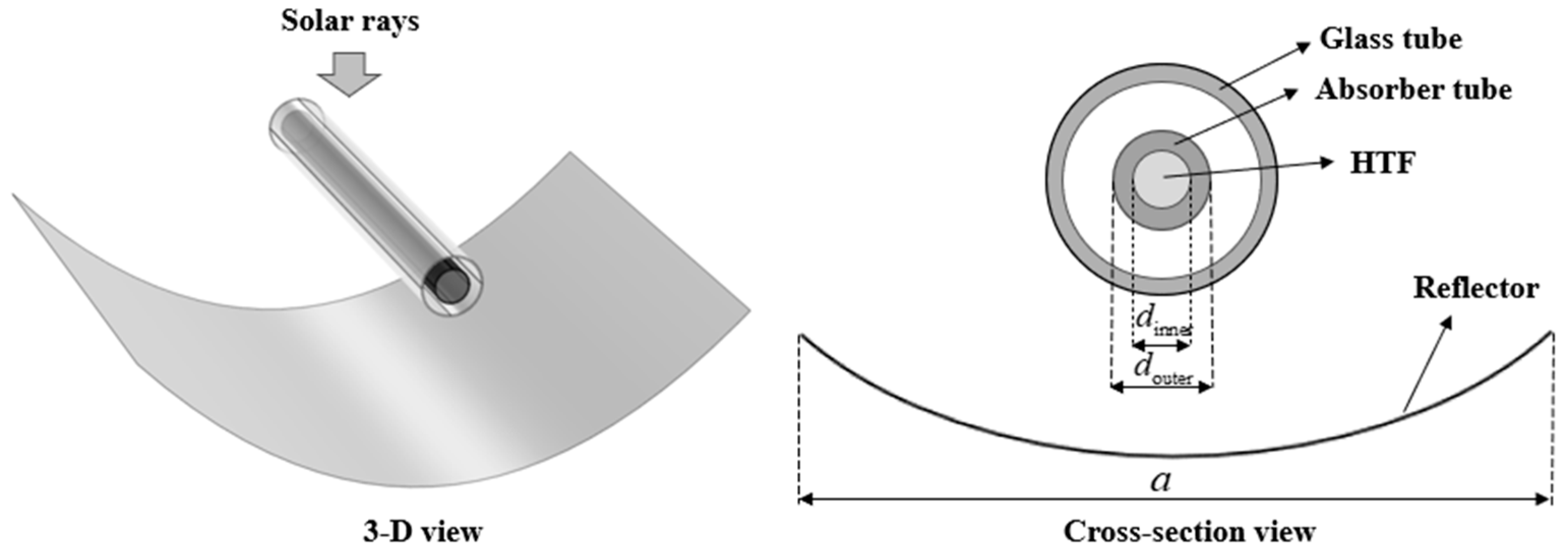
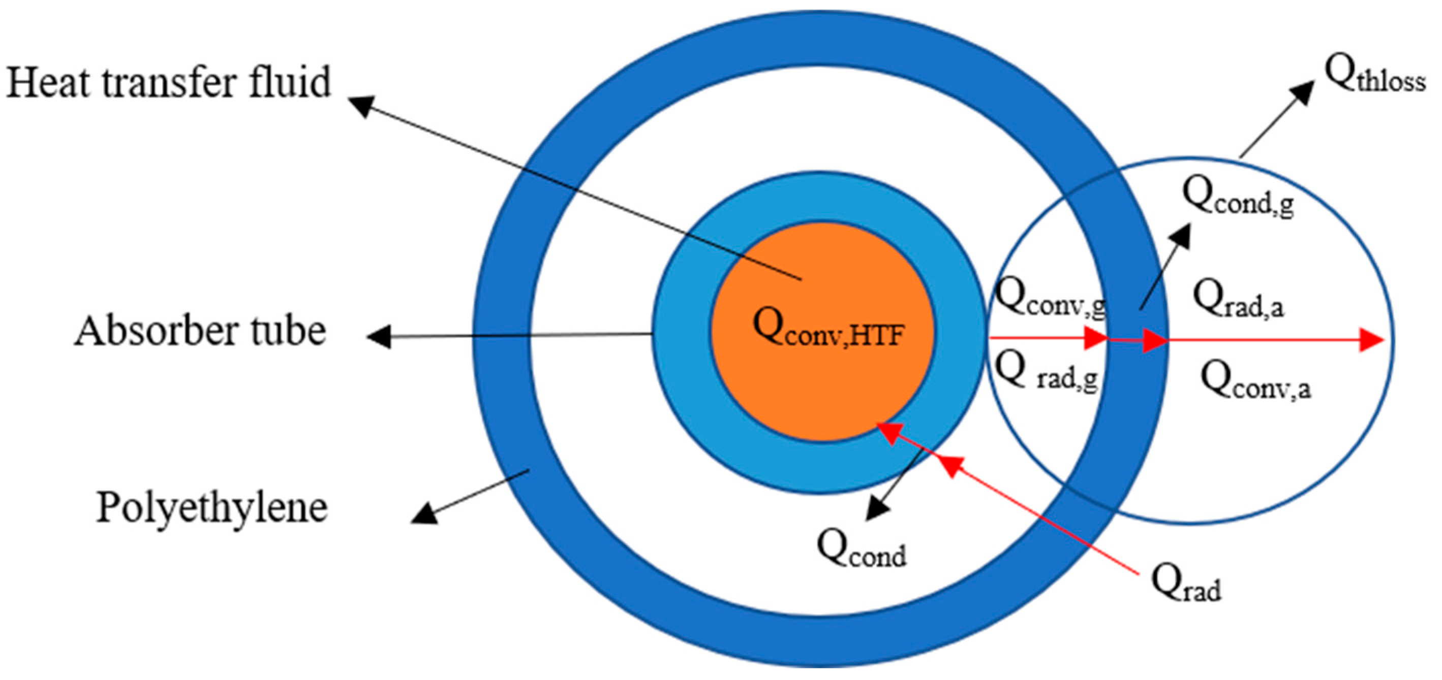
2.1. Concentrated Heat Collection Model

The PTC collector loop mainly consists of an absorber tube, a glass tube, a parabolic trough reflector, and some connecting supports (see Figure 1), with a vacuum between the glass tube and the absorber tube. During the heat collection process, the parabolic trough reflector concentrates the solar radiation energy into the heat transfer fluid inside the absorber tube. The collector parameters [23] and heat transfer fluid parameters [24] used in the numerical model of this paper are shown in Table 1 and Table 2.
The heat flux of solar radiation collected in the absorber tube can be expressed as [25]:
Q rad = D N I A reflector η opt cos θ IAM
In the formula, DNI is the direct normal irradiance of solar radiation; A reflector is the aperture area of the parabolic trough reflector. η opt is the optical efficiency of the collector (a portion of solar energy is lost during reflection, transmission, and absorption processes). θ is the angle of incidence of sunlight, and IAM is the incidence angle modifier. When 0 ° θ < 8 0 ° , the IAM of the LS-3 concentrator can be expressed as [25]:
IAM = 1 2.23073 e 4 θ 1.1 e 4 θ 2 + 3.18596 e 4 θ 3 4.88509 e 8 θ 4
The energy transfer relationship of the absorber tube [26] is shown in Figure 2. After the energy from solar radiation is concentrated in the collector tube, it is transferred to the Heat Transfer Fluid (HTF) through conduction between the inner and outer walls of the absorber tube (Qcond) and convective heat transfer between the HTF and the inner wall of the absorber tube (Qconv,HTF). A portion of the energy is also lost to the environment through convective and radiative heat transfer (Qthloss). Based on the above energy transfer relationship, the heat transfer model of the collector tube in the transient process can be expressed as [25,27]:
ρ ab c ab A ab t w 2 τ l = Q rad Q thloss Q cond
ρ ab c ab A ab t w 1 τ l = Q cond Q conv , HTF
Among them [26]:
Q cond = 2 π k ab l ( t w 2 t w 1 ) In ( d outer / d inner )
Q conv , HTF = h conv , HTF π d inner l ( t w 1 t HTF )
In the equation, kab represents the thermal conductivity of the absorber tube; hconv,HTF presents the convective heat transfer coefficient between the HTF and the inner wall of the absorber tube (the HTF flow in this paper is single-phase flow; for single-phase models, h conv , HTF = N u k ab / d inner , when the flow is laminar, N u = 4.36 , when the flow is turbulent, it is calculated using the Gnielinski equation N u [28]); d inner , d outer and l represent the inner and outer diameters of the absorber tube and the discrete unit length of the circuit, respectively; t w 1 , t w 2 and t HTF represent the temperatures of the inner and outer walls of the absorber tube and the average temperature of the HTF, respectively.
The temperature of the outer wall of the absorber tube (HTF) is closely related and can be simplified as [25,27]:
Q thloss = ( 0.16155 t w 2 + 6.4407 e 9 t w 2 4 ) π d outer l

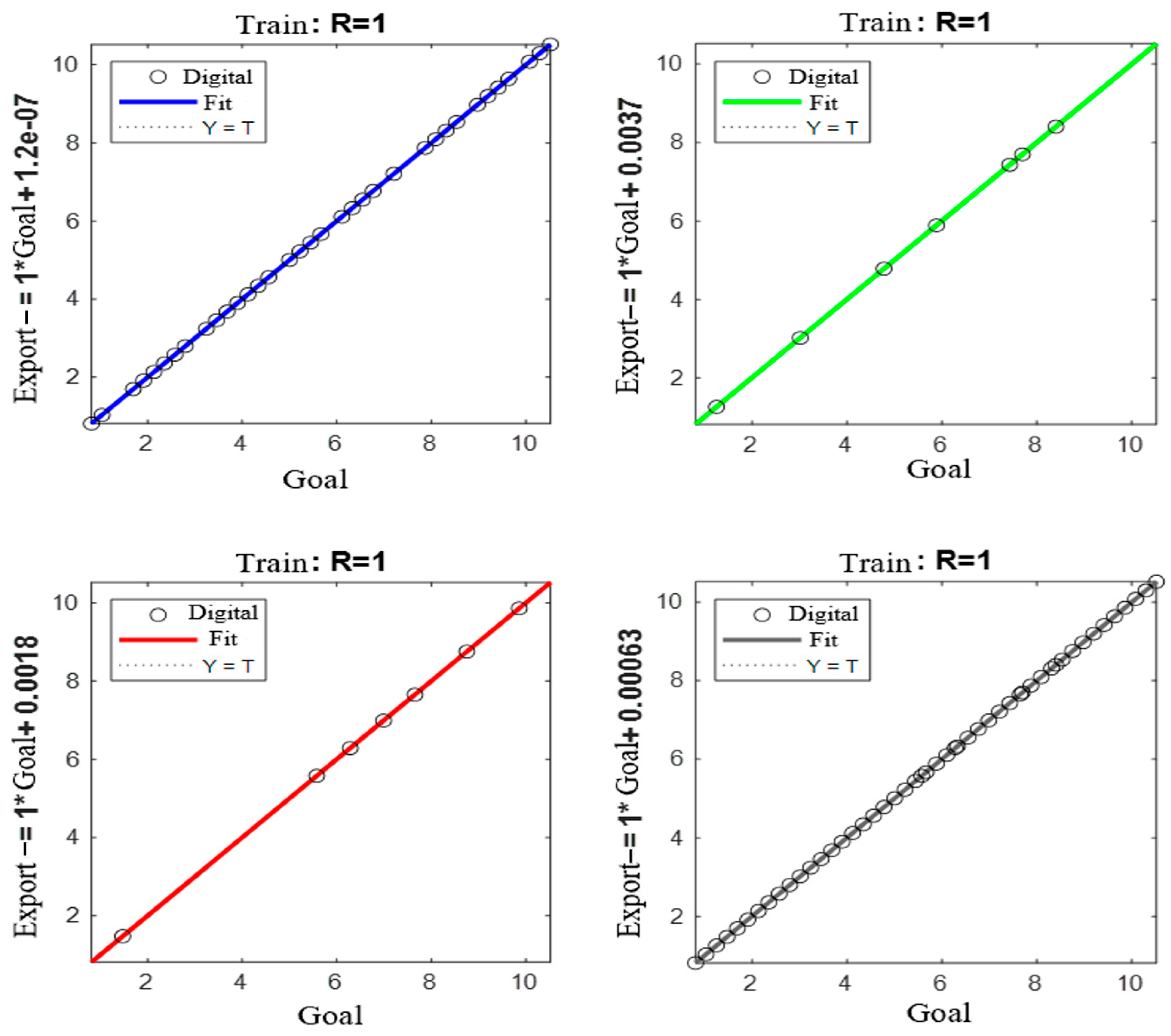
2.2. Artificial Neural Network Feedforward-Feedback Control Model for PTC Collector Circuit

The artificial neural network is a computational model designed to simulate the neural networks of the human brain, structurally and functionally mimicking them, capable of modeling and predicting relationships between data [29], and has the potential to address challenges in establishing mathematical models for feedforward control in PTC collector circuits. Feedforward control reacts quickly, but its robustness is relatively poor; if the feedforward information is inaccurate, the precision and stability of the control cannot be guaranteed. Feedback control ensures stability and precision but has higher delays and difficulties in controlling overshoot. This study combines the advantages of artificial neural networks, feedforward control, and feedback control to propose an Artificial Neural Network Feedforward-Feedback (ANN-FF-FB) control model, regulating the outlet temperature of the PTC collector circuit by adjusting the mass flow rate. Figure 3 shows the schematic of the ANN-FF-FB control model, which primarily consists of the feedforward control component of the artificial neural network and the feedback control component. The feedforward control section of the artificial neural network consists mainly of the irradiance prediction neural network and the feedforward control neural network. The role of the irradiance prediction neural network is to forecast solar irradiance intensity (DNI) at different times, providing the feedforward control neural network with certain feedforward information before meteorological disturbances occur, which can be continuously corrected based on actual DNI data during operation, ultimately eliminating the need for a meteorological data collection system. The feedforward control neural network’s role is to derive the feedforward adjustment signal for mass flow rate in response to changes in solar irradiance intensity. The control process is as follows:
When meteorological disturbances occur, the feedforward control neural network calculates the feedforward adjustment signal for mass flow rate based on the actual solar irradiance intensity, controlling the outlet temperature of the circuit through feedforward control. Simultaneously during the feedforward control phase, the temperature sensor at the circuit outlet transmits the measured temperature signal to the feedback controller, resulting in the feedback adjustment quantity for mass flow rate, which corrects the outlet temperature of the circuit. The ANN-FF-FB control model combines the speed of feedforward control, the stability and precision of feedback control, and the learning and data processing capabilities of artificial neural networks, enabling a composite control that integrates regional irradiance data prediction, feedforward adjustment, and real-time feedback adjustment for the PTC collector circuit, ensuring stable operation of the circuit.
The ANN-FF-FB control model consists of two main parts: the feedforward control section and the feedback control section. The feedforward control section requires training of the irradiation prediction neural network and the feedforward control neural network. MATLAB2019 neural network toolbox is used to train the irradiation prediction and feedforward control neural networks, and the coefficient of determination R is used to evaluate the trained network. The closer R is to 1, the better the neural network’s performance [21]. The expression for R is as follows:
R = 1 i = 1 n ( x ( i ) x n n ( i ) ) 2 i = 1 n ( x ( i ) x ¯ n n ) 2
In the formula, x(i) represents the actual value of the data, xnn(i) represents the neural network’s computed value, and x ¯ represents the mean of x(i).
The first step is to train the irradiation prediction neural network. The input to the network is time (month, date, and time), and the output is DNI. The training data consist of the DNI variation data for different times of each day in Zhengzhou, excluding typical days of the four seasons. These data are sourced from EnergyPlus [30]. These data are imported into the MATLAB neural network training toolbox, with 70% used for training, 15% for validation, and 15% for testing. The neural network used for training is a three-layer feedforward neural network with two hidden layers and one output layer. Each hidden layer contains 50 neurons, with the activation function being the sigmoid function. The output layer contains one neuron with a linear activation function. The training algorithm is the Levenberg–Marquardt backpropagation algorithm. The training results of the neural network are shown in Figure 4. It can be observed that the R value for the training set is close to 1, and the R values for the validation and test sets are close to 0.9, indicating good performance of the neural network, which essentially meets the requirements for weather prediction.
Then, the training of the feedforward control neural network was conducted. This neural network serves to determine the feedforward regulation signal of mass flow rate when solar irradiance varies, thereby implementing feedforward control on the outlet temperature of the parabolic trough collector (PTC) solar loop. The input parameter of this neural network is the Direct Normal Irradiance (DNI), while the output corresponds to the heat transfer fluid mass flow rate. The training data were derived from computational results of the numerical model. As illustrated in Figure 5, which demonstrates the correlation between solar irradiance and mass flow rate under different target outlet temperatures of the PTC solar loop, these data enable the determination of required mass flow rates to maintain specified outlet temperatures during DNI fluctuations. These datasets were imported into MATLAB Neural Network Toolbox for training, with data partitioned as 70% for training, 15% for validation, and 15% for testing.
The implemented neural network architecture consists of a two-layer feedforward structure comprising one hidden layer and one output layer. The hidden layer contains 10 neurons with sigmoid activation functions, while the output layer employs a single neuron with linear activation. The Levenberg-Marquardt backpropagation algorithm was adopted as the training algorithm. The training outcomes presented in Figure 6 demonstrate that the R-values for training, validation, and testing datasets all approximate 1, indicating excellent network performance. By inputting real-time DNI data into the trained neural network, the corresponding feedforward mass flow control signal can be obtained. This control signal can be mathematically expressed as:
Δ m HTF , FF ( τ ) = K NN D N I ( τ )
In the formula, Knn represents the feedforward control neural network.
The trained neural network is mainly used for the feedforward control part of the ANN-FF-FB control model. When the DNI changes, the feedforward control part immediately calculates the feedforward adjustment of the mass flow through the neural network to control the outlet temperature of the PTC heat collection loop. Feedforward control responds quickly, but its robustness is poor. If both the measured and predicted DNI values are inaccurate, the feedforward control part cannot ensure the stability of the loop outlet temperature. At this time, the feedback control part is needed to correct the outlet temperature to ensure control effectiveness.

2.3. PID Control Model

The principle of PID control is to use the deviation between the actual value and the set value of the collector mirror field’s outlet temperature to form a control signal through proportional, integral, and derivative components, which controls the flow of the heat transfer fluid to maintain the stability of the outlet temperature. The flow control signal in PID control can be expressed as [14]:
Δ m HTF ( τ ) = K P e ( τ ) + K I 0 τ e ( τ ) d τ + K D d e ( τ ) d τ
where e ( τ ) is the deviation between the actual and set values of the loop outlet temperature; K P , K I , and K D are the proportional, integral, and derivative coefficients, respectively. The PID control coefficients in this paper are referenced from the parameters in literature [14] ( K P = 1, K I = 0.05–0.09).

2.4. Numerical Algorithm

This paper uses the SIMPLE algorithm [6] to solve the transient flow and heat transfer coupling model of the PTC loop. The finite volume method (FVM) under a staggered grid is used to discretize the mass, momentum, and energy equations of the HTF. The mass and energy equations are integrated within the main control volume, while the momentum equation is integrated within adjacent control volumes. The independent variables selected for calculation are the specific enthalpy, pressure, density, velocity, and temperature of the HTF. The transient terms in the equations are discretized using the backward Euler method (implicit), the other terms using a semi-implicit scheme, and the convection terms using the QUICK scheme.

3. Results and Discussion

Based on the previously proposed neural network control model, this section first analyzes the control performance of the neural network control model in maintaining the stability of the collector loop outlet temperature in response to weather disturbances and compares it with the classical PID control model. It then analyzes and compares the control performance of the neural network control model and the PID control model when changing the collector loop outlet temperature to the set point t out . Finally, it analyzes the performance and advantages of the neural network control model under actual weather conditions. A representative operational scenario of a parabolic trough collector (PTC) system was selected, with initial operating parameters configured as follows [6,12]: solar irradiance DNI = 850 W/m2, collector loop inlet temperature t in = 293 °C, collector loop outlet temperature t out = 393 °C, and the main control variable, heat transfer fluid mass flow rate m HTF = 7.35 kg/s.

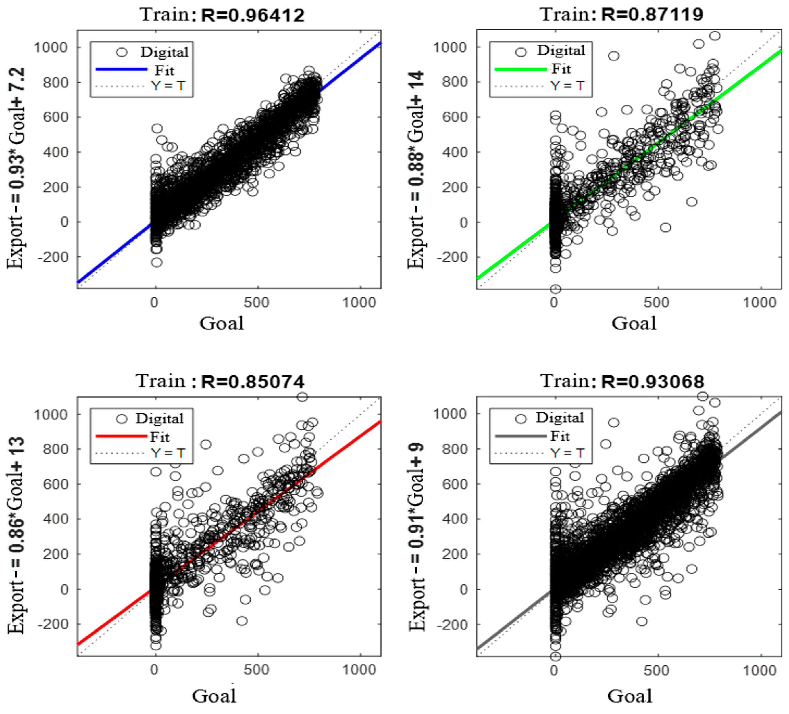
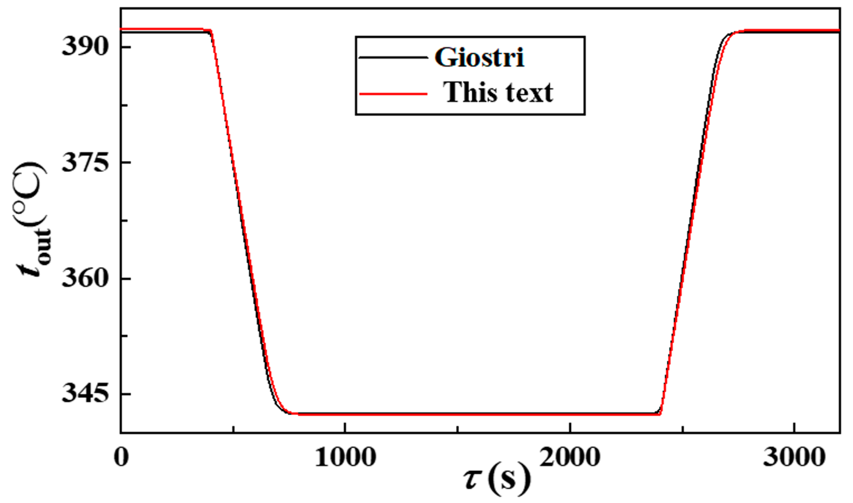
3.1. Model Validation

The validation of the model in this paper was compared with the calculation results of Giostri [31]. He analyzed the impact of step changes in DNI (τ = 0 s, DNI = 800 W·m−2; τ = 400 s, DNI = 400 W·m−2; τ = 800 s, DNI = 800 W·m−2) on the transient outlet temperature of HTF. The HTF used was Therminol VP-1, with a mass flow rate of 7.7 kg·s−1 and an inlet temperature of 293 °C. The transient variation of HTF outlet temperature is shown in Figure 7. Under the same conditions, the maximum relative deviation between the calculation results of the model in this paper and the literature results is 1.2%, verifying the reliability and accuracy of the model.

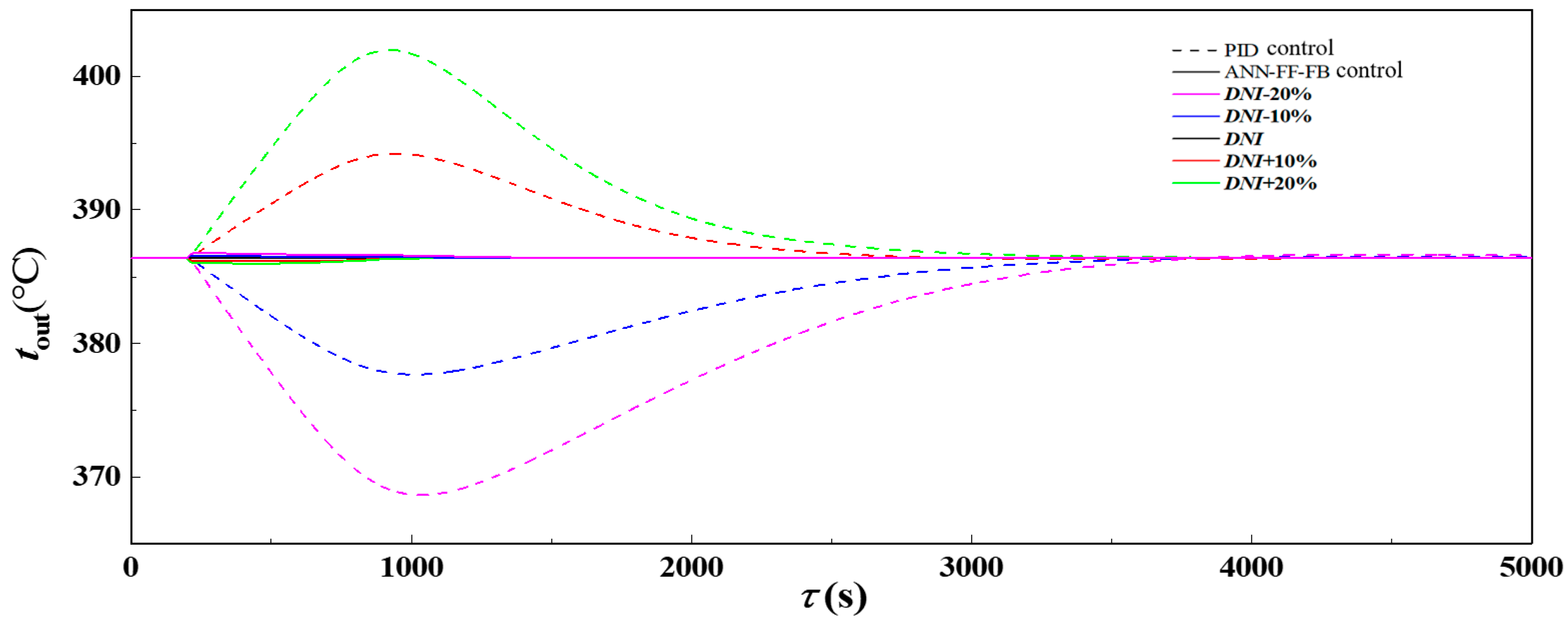
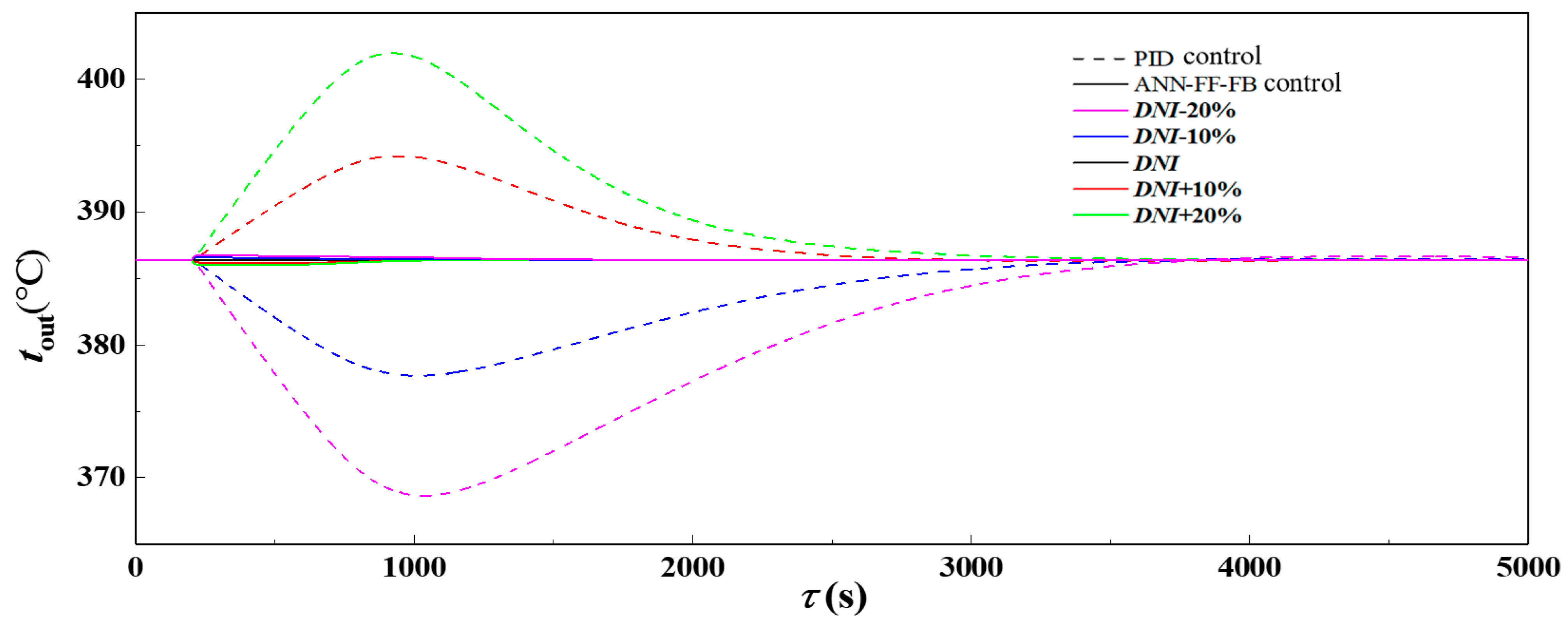
3.2. Control Performance Analysis Under Step Changes in Solar Irradiance

The solar irradiance (DNI) is the most significant uncontrollable meteorological factor affecting the operation of the PTC collector loop. To evaluate the control performance of the ANN-FF-FB control model, this section analyzes its performance under step changes in solar irradiance.
Assuming the system operates steadily under initial conditions (DNI = 800 W/m2, tin = 280 °C, mHTF = 7 kg/s, tout = 386.4 °C), a step change in solar irradiance occurs at 200 s, and both the ANN-FF-FB control model and PID control model are used to adjust the mass flow rate to stabilize the outlet temperature of the PTC collector loop. Figure 8 shows the transient response curves of the outlet temperature of the PTC collector loop under different control models during step changes in solar irradiance. From the figure, it can be seen that both control models can maintain the outlet temperature at the initial value for a period of time, with both having small steady-state errors, ensuring accurate control. The steady-state error range of the ANN-FF-FB control model is 0.02–0.06 °C, while that of the PID controller is 0.02–0.15 °C, indicating that the former has greater advantages in thermal regulation accuracy and operational stability.
As shown in Figure 8, when the solar irradiance undergoes a step decrease of 20%, the maximum regulation time for the PID control model is 3596 s, whereas the ANN-FF-FB model requires only 812 s, approximately one-quarter of the PID model’s time. Additionally, the ANN-FF-FB model exhibits an extremely low overshoot (a maximum of only 0.5 °C), ensuring control stability. In contrast, the PID model experiences an overshoot of 15.58 °C when the solar irradiance steps up by 20%, causing the outlet temperature to exceed the thermal stability threshold of the heat transfer oil (400 °C), which may lead to coking failure in the PTC heat-absorbing tube circuit. This clearly demonstrates the significant advantages of the ANN-FF-FB model in terms of response speed and control accuracy.
Figure 9 shows the transient response curves of mass flow rate under different control models during step changes in solar irradiance. From the figure, it can be seen that the standalone PID control requires a longer time to adjust the mass flow rate to the desired value. This is because the PID control algorithm must calculate the adjustment amount based on the deviation between the actual and set outlet temperatures, and the transient changes in outlet temperature require a certain amount of time, resulting in a longer adjustment time. In contrast, the ANN-FF-FB control model can directly compute the required mass flow rate adjustment using the feedforward control neural network when changes in solar irradiance occur, which is then corrected by the PID control. At this time, the mass flow rate that needs adjustment is already quite small, resulting in a faster adjustment time. Figure 10 shows the variation of the accumulated entropy production of the absorber tube during the transient process under different control models with step changes in solar irradiance. It can be observed that the accumulated entropy production of the absorber tube significantly decreases when controlled by the ANN-FF-FB control model. When the solar irradiance increases by 20%, the accumulated entropy production during the transient process is reduced by up to 89.41% compared to when there is no control, due to the significant reduction in the adjustment time of the system by the ANN-FF-FB control model. Conversely, the standalone PID control model tends to increase the accumulated entropy production of the absorber tube during the transient process, which is attributed to the longer adjustment time of PID control, resulting in an extended transient process.
From the above analysis, it can be concluded that during step changes in solar irradiance, the ANN-FF-FB control model can control the outlet temperature of the PTC collector loop quickly, accurately, and stably. The adjustment time of the ANN-FF-FB control model is only one-quarter of that of the PID control model under the same conditions, with a maximum overshoot of only 0.5 °C and a steady-state error of only 0.02 °C, keeping the outlet temperature within a stable range and ensuring the stable operation of the PTC collector loop. Furthermore, the ANN-FF-FB control model can also reduce the accumulated entropy production of the absorber tube during the transient process, enhancing the thermodynamic performance of the PTC collector loop.

3.3. Analysis of Control Performance When Adjusting the Set Point of Outlet Temperature

During actual operation, the PTC collector loop sometimes needs to adjust the outlet temperature set point based on different power loads, which is critical for the energy dispatch and operational flexibility of the PTC power plant. Therefore, the ability to quickly and accurately adjust the outlet temperature set point is an important criterion for evaluating a PTC collector loop control model. To further assess the performance of the ANN-FF-FB control model, this section analyzes the model’s performance when adjusting the set point of the outlet temperature. Assuming the system operates steadily under initial conditions, the ANN-FF-FB control model and the PID control model are used to adjust the outlet temperature set point simultaneously at 200 s. Figure 11 shows the transient response curves of outlet temperature when adjusting the set point under different control models. As seen from the figure, both the ANN-FF-FB control model and the PID control model can adjust the outlet temperature set point to the desired value after a period of time, ensuring control accuracy. The steady-state error of the ANN-FF-FB control model is only 0.03 °C at most, while the PID control model’s maximum steady-state error is 0.05 °C. However, the adjustment time of the ANN-FF-FB control model is significantly shorter compared to the PID control model, demonstrating better responsiveness. When lowering the outlet temperature set point by 15 °C, the PID control model’s maximum adjustment time is 3518 s, whereas the ANN-FF-FB control model takes only 1019 s, less than one-third of the PID control model’s time.
Figure 12 shows the transient response curve of mass flow rate when adjusting the set point of outlet temperature under different control models. As seen in the figure, when adjusting the set point, the standalone PID control takes a long time to adjust the mass flow rate to the desired value, as the PID control model calculates the adjustment amount based on the deviation between the actual and set values of the outlet temperature, which takes time to respond. In contrast, the ANN-FF-FB control model quickly calculates the required mass flow rate adjustment through a feedforward neural network, resulting in faster adjustment times.
From the above analysis, both the ANN-FF-FB control model and the PID control model can adjust the PTC collector loop outlet temperature to the desired set point within a period of time, ensuring control accuracy. However, the adjustment time of the ANN-FF-FB control model is significantly shorter compared to the PID control model, demonstrating superior responsiveness.

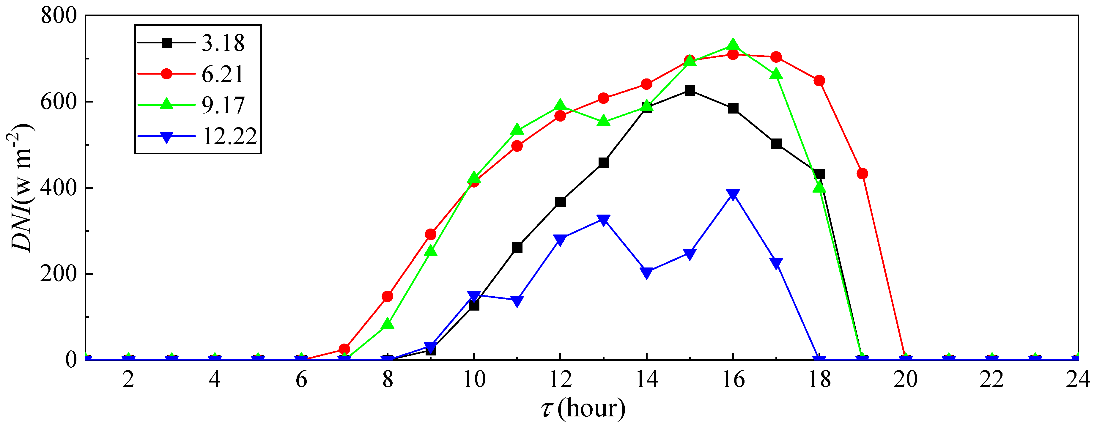
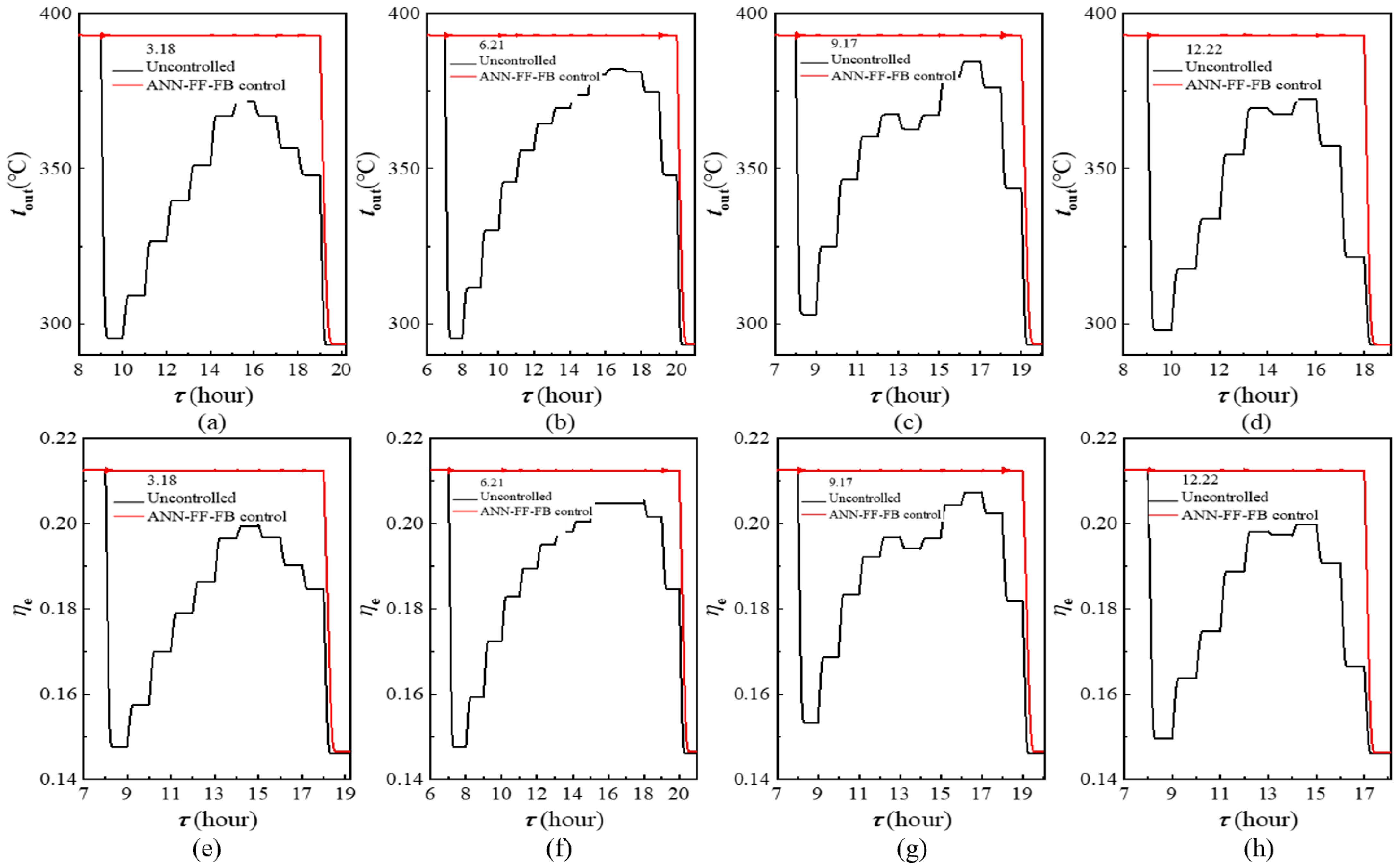
3.4. Control Performance Analysis Under Actual Meteorological Conditions

Actual weather conditions exhibit greater complexity, where solar irradiance rarely follows simple stepwise variations, posing new challenges for parabolic trough collector (PTC) control. To further evaluate the neural control model proposed in this study, we se-lected Zhengzhou, a city in central China, as the application scenario for PTC technology. The neural network control model was employed to regulate the outlet temperature tout Figure 13 presents solar irradiance data for four seasonally representative days in Zhengzhou. As shown, the irradiance intensity and duration on June 21 and September 17 significantly exceed those on March 18 and December 22. Initial conditions assume tout reaches 393 °C prior to sunrise through auxiliary startup measures, with subsequent me-teorological variations governed by Zhengzhou’s weather data. The neural network con-trol model was activated from sunrise to sunset to stabilize tout Figure 14a–d illustrate the control performance of the neural network model on tout under actual weather conditions across the four typical days. Without control, tout exhibits pronounced fluctuations: a sharp decline occurs at sunrise due to insufficient ir-radiance, followed by gradual increases as irradiance strengthens. Peak values (371.83 °C, 382.03 °C, 384.59 °C, and 372.47 °C for March 18, June 21, September 17, and December 21, respectively) emerge between 14:00 and 16:00 before declining with diminishing irradi-ance. All uncontrolled maxima remain below 393 °C. In contrast, the neural network con-trol stabilizes tout near 393 °C throughout daylight hours, with maximum overshoots below 1 °C, demon-strating robust annual performance.
Figure 14e–f depict corresponding variations in thermal efficiency ηe during tout regulation. Uncontrolled ηe fluctuates synchronously with irradiance, gradually adjusting to new steady states during irradiance transitions, with peak values of 0.197, 0.205, 0.207, and 0.199 on the respective dates. Under neural network control, ηe stabilizes near 0.212 throughout daylight hours, consistently outperforming uncontrolled conditions.
From the above analysis, it is evident that the ANN-FF-FB control model proposed in this paper can effectively control the system under actual weather condition changes, keeping the temperature stable near the set value. Compared to the rugged fluctuations without control, the stability significantly improves after adjustment by the ANN-FF-FB control model, and the energy utilization efficiency is also higher than when uncontrolled. The ANN-FF-FB control model proposed in this paper demonstrates good control effectiveness in response to actual weather condition changes, which is of great significance for the stable and efficient operation of PTC power plants.

4. Conclusions

The intermittency and fluctuation of solar irradiation bring significant challenges to the control of PTC heat collection loops. The control of PTC heat collection loops is crucial for improving their stability and dynamic controllability, but further research on control methods is still needed. In response to the above issues, the main work and conclusions of this chapter are as follows:
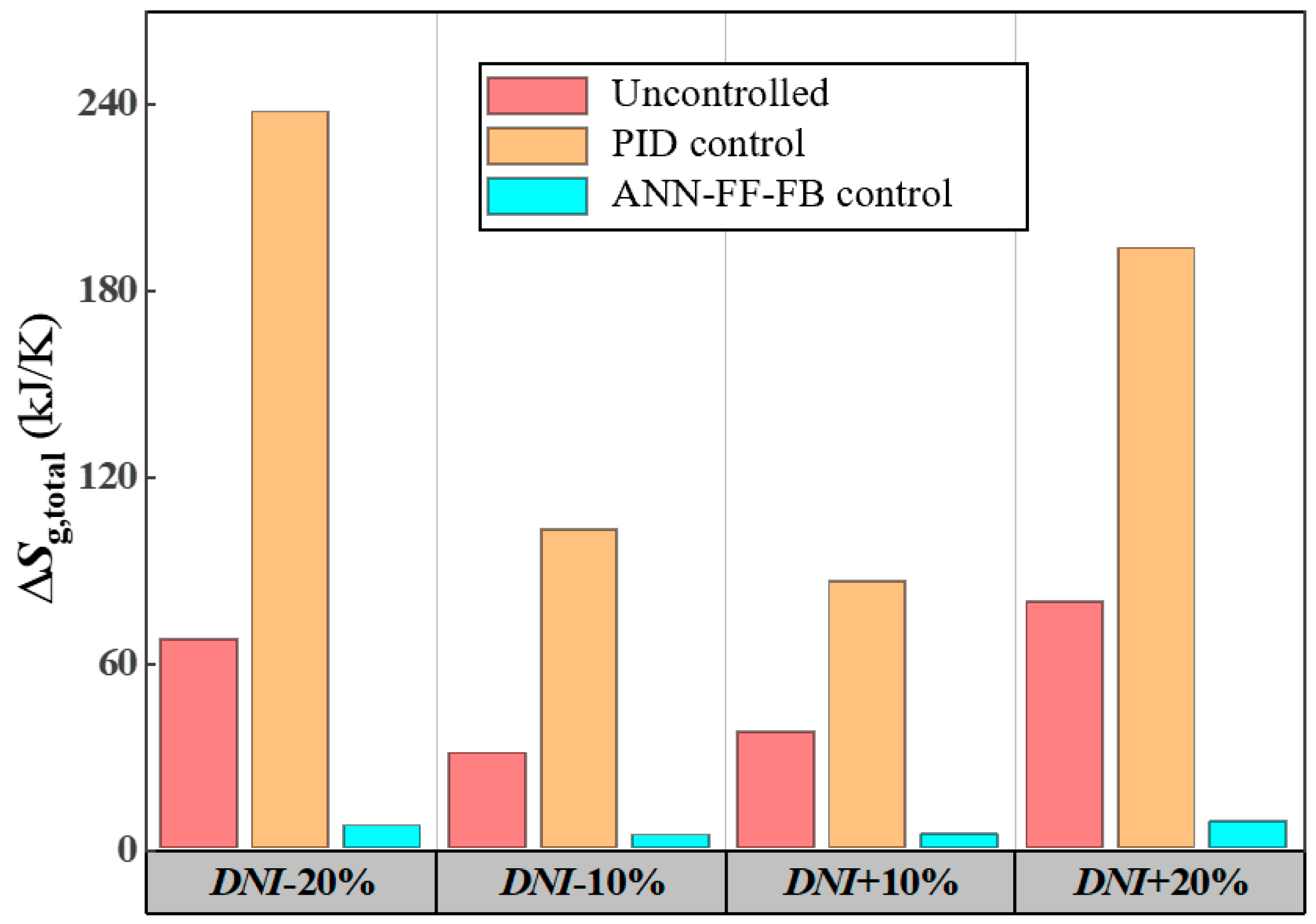
  • The ANN-FF-FB control model demonstrates superior response speed, accuracy, and stability during step changes in solar irradiance. Its adjustment time is only one-quarter of that of the PID control model, with a maximum overshoot of only 0.5 °C and a steady-state error of just 0.02 °C, effectively maintaining the stable operation of the PTC collector loop outlet temperature. Furthermore, this model significantly reduces the accumulated entropy production in the absorber tube during transient processes, improving the thermodynamic performance of the PTC collector loop and ensuring its stable operation.
  • When adjusting the setpoint, the ANN-FF-FB control model shows superior response speed and control accuracy in adjusting the outlet temperature setpoint of the PTC collector loop. Its adjustment time is less than one-third of the PID control model’s time, with a maximum steady-state error of only 0.03 °C. In contrast, the PID control model takes longer to adjust, while the ANN-FF-FB control model quickly calculates the required mass flow rate adjustment using a feedforward neural network, significantly improving the responsiveness of the control system.
  • The ANN-FF-FB control model effectively stabilizes the outlet temperature of the PTC collector loop under actual weather condition changes, maintaining it close to the setpoint from sunrise to sunset with a maximum overshoot of less than 1 °C, while also improving energy utilization efficiency. Compared to the significant fluctuations without control, this model greatly enhances the system’s stability, which is of great significance for the stable and efficient operation of PTC power plants.

Author Contributions

Conceptualization, B.A., L.L. and F.G.; Methodology, B.A., Q.Z., L.L. and K.W.; Software, B.A.; Validation, K.W.; Investigation, Q.Z.; Resources, F.G. and J.Y.; Writing—original draft, B.A. and F.G.; Writing—review & editing, L.L.; Project administration, J.Y.; Funding acquisition, K.W. All authors have read and agreed to the published version of the manuscript.

Funding

This work was supported by the Science and Technology Project of Henan Province (222102320020).

Institutional Review Board Statement

Not applicable.

Informed Consent Statement

Not applicable.

Data Availability Statement

The original contributions presented in this study are included in the article. Further inquiries can be directed to the corresponding author.

Conflicts of Interest

The authors declare no conflict of interest.

References

  1. Weinstein, L.A.; Loomis, J.; Bhatia, B.; Bierman, D.M.; Wang, E.N.; Chen, G. Concentrating Solar Power. Chem. Rev. 2015, 115, 12797–12838. [Google Scholar] [CrossRef]
  2. Liu, X.; Zhang, Y.; Fu, S.; Wan, L.; Wang, H.; Zhang, Y.; Liu, Z.; Peng, J.; Li, J.; Song, C. In-Depth Investigation of Morphology Evolution in Highly Efficient Pseudo-Planar Heterojunction All-polymer Organic Photovoltaics. Adv. Funct. Mater. 2025, 2500975. [Google Scholar] [CrossRef]
  3. Zhang, Y.; Zhang, Y.; Liu, X.; Geng, Z.; Wang, H.; Xu, Z.; Miao, Z.; Liang, Q.; Liu, J. Controlling the Third Component Distribution Toward High-Efficient Ternary Organic Solar Cells. Adv. Energy Mater. 2025, 2406136. [Google Scholar] [CrossRef]
  4. Wang, G.; Chao, Y.C.; Jiang, T.L.; Chen, Z.S. Facilitating developments of solar thermal power and nuclear power generations for carbon neutral: A study based on evolutionary game theoretic method. Sci. Total Environ. 2022, 814, 151927. [Google Scholar] [CrossRef]
  5. He, Y.-L.; Qiu, Y.; Wang, K.; Yuan, F.; Wang, W.-Q.; Li, M.-J.; Guo, J.-Q. Perspective of concentrating solar power. Energy 2020, 198, 117373. [Google Scholar] [CrossRef]
  6. Li, L.; Sun, J.; Li, Y.; He, Y.-L.; Xu, H. Transient characteristics of a parabolic trough direct-steam-generation process. Renew. Energy 2019, 135, 800–810. [Google Scholar] [CrossRef]
  7. Qiu, Y.; Xu, Y.; Li, Q.; Wang, J.; Wang, Q.; Liu, B. Efficiency enhancement of a solar trough collector by combining solar and hot mirrors. Appl. Energy 2021, 299, 117290. [Google Scholar] [CrossRef]
  8. Zhang, S.; Liu, M.; Zhao, Y.; Liu, J.; Yan, J. Dynamic simulation and performance analysis of a parabolic trough concentrated solar power plant using molten salt during the start-up process. Renew. Energy 2021, 179, 1458–1471. [Google Scholar] [CrossRef]
  9. Camacho, E.F.; Rubio, F.R.; Berenguel, M.; Valenzuela, L. A survey on control schemes for distributed solar collector fields. Part I: Modeling and basic control approaches. Sol. Energy 2007, 81, 1240–1251. [Google Scholar] [CrossRef]
  10. Camacho, E.F.; Rubio, F.R.; Berenguel, M.; Valenzuela, L. A survey on control schemes for distributed solar collector fields. Part II: Advanced control approaches. Sol. Energy 2007, 81, 1252–1272. [Google Scholar] [CrossRef]
  11. Behera, A.R.; Mallick, R.K.; Agrawal, R.; Nayak, P.; Sinha, S. Performance Analysis of Fuzzy-PID Controller in Nuclear, dish-Stirling Solar Thermal and Reheat Thermal Energy Integrated Deregulated Power System. In Proceedings of the 2022 International Conference on Intelligent Controller and Computing for Smart Power (ICICCSP), Hyderabad, India, 21–23 July 2022; p. 6. [Google Scholar] [CrossRef]
  12. Li, L.; Li, Y.; Yu, H.; He, Y.-L. A feedforward-feedback hybrid control strategy towards ordered utilization of concentrating solar energy. Renew. Energy 2020, 154, 305–315. [Google Scholar] [CrossRef]
  13. Mokhtar, M.; Zahler, C.; Stieglitz, R. Control of Concentrated Solar Direct Steam Generation Collectors for Process Heat Applications. J. Sol. Energy Eng. 2022, 144, 011005. [Google Scholar] [CrossRef]
  14. Li, L.; Li, Y.; He, Y.-L. Flexible and efficient feedforward control of concentrating solar collectors. Appl. Therm. Eng. 2020, 171, 115053. [Google Scholar] [CrossRef]
  15. Zayed, M.E.; Zhao, J.; Li, W.; Sadek, S.; Elsheikh, A.H. Chapter three—Applications of artificial neural networks in concentrating solar power systems. In Artificial Neural Networks for Renewable Energy Systems and Real-World Applications; Elsheikh, A.H., Abd Elaziz, M.E., Eds.; Academic Press: Cambridge, MA, USA, 2022; pp. 45–67. [Google Scholar]
  16. Moukhtar, I.; Elbaset, A.A.; El Dein, A.Z.; Qudaih, Y.; Blagin, E.; Uglanov, D.; Mitani, Y. A Developed Concentrated Solar Power Model Using Artificial Neural Network Technique. In Proceedings of the 9th International Middle East Power Systems Conference (MEPCON), Nasr City, Egypt, 19–21 December 2017; pp. 1346–1351. [Google Scholar]
  17. Kalogirou, S.A. Artificial neural networks in renewable energy systems applications: A review. Renew. Sustain. Energy Rev. 2001, 5, 373–401. [Google Scholar] [CrossRef]
  18. Vaferi, B.; Samimi, F.; Pakgohar, E.; Mowla, D. Artificial neural network approach for prediction of thermal behavior of nanofluids flowing through circular tubes. Powder Technol. 2014, 267, 1–10. [Google Scholar] [CrossRef]
  19. Ebrahimi-Moghadam, A.; Mohseni-Gharyehsafa, B.; Farzaneh-Gord, M. Using artificial neural network and quadratic algorithm for minimizing entropy generation of Al2O3-EG/W nanofluid flow inside parabolic trough solar collector. Renew. Energy 2018, 129, 473–485. [Google Scholar] [CrossRef]
  20. May Tzuc, O.; Bassam, A.; Escalante Soberanis, M.; Venegas-Reyes, E.; Jaramillo, O.; Ricalde, L.J.; Ordoñez, E.E.; El Hamzaoui, Y. Modeling and optimization of a solar parabolic trough concentrator system using inverse artificial neural network. J. Renew. Sustain. Energy 2017, 9, 013701. [Google Scholar]
  21. Ajbar, W.; Parrales, A.; Cruz-Jacobo, U.; Conde-Gutiérrez, R.A.; Bassam, A.; Jaramillo, O.A.; Hernández, J.A. The multivariable inverse artificial neural network combined with GA and PSO to improve the performance of solar parabolic trough collector. Appl. Therm. Eng. 2021, 189, 116651. [Google Scholar] [CrossRef]
  22. Cervantes-Bobadilla, M.; Hernández-Pérez, J.; Juárez-Romero, D.; Bassam, A.; García-Morales, J.; Huicochea, A.; Jaramillo, O. Control scheme formulation for a parabolic trough collector using inverse artificial neural networks and particle swarm optimization. J. Braz. Soc. Mech. Sci. Eng. 2021, 43, 176. [Google Scholar] [CrossRef]
  23. Qiu, Y.; Li, M.-J.; He, Y.-L.; Tao, W.-Q. Thermal performance analysis of a parabolic trough solar collector using supercritical CO2 as heat transfer fluid under non-uniform solar flux. Appl. Therm. Eng. 2017, 115, 1255–1265. [Google Scholar] [CrossRef]
  24. Serrano-Lopez, R.; Fradera, J.; Cuesta-Lopez, S. Molten salts database for energy applications. Chem. Eng. Process. 2013, 73, 87–102. [Google Scholar] [CrossRef]
  25. Cruz, J.B.; Muñoz, L.J.Y.; Bencomo, S.D.; Moya, E.Z. Modeling and Simulation of Two-Phase Flow Evaporators for Parabolic-Trough Solar Thermal Power Plants. 2013. Available online: http://documenta.ciemat.es/handle/123456789/195 (accessed on 8 March 2025).
  26. Kalogirou, S.A. A detailed thermal model of a parabolic trough collector receiver. Energy 2012, 48, 298–306. [Google Scholar]
  27. Feldhoff, J.F. Analysis of Once-Through Boiler Concepts in Parabolic Troughs. RWTH Aachen 2015. Available online: http://documenta.ciemat.es/handle/123456789/195 (accessed on 8 March 2025).
  28. Li, L.; Sun, J.; Li, Y. Prospective fully-coupled multi-level analytical methodology for concentrated solar power plants: General modelling. Appl. Therm. Eng. 2017, 118, 171–187. [Google Scholar] [CrossRef]
  29. Theodoridis, S. Neural Networks and Deep Learning. 2016. [Google Scholar]
  30. Available online: https://energyplus.net/weather (accessed on 1 December 2022).
  31. Giostri, A. Transient effects in linear concentrating solar thermal power plant. Bibl. E Arch. 2014. Available online: https://hdl.handle.net/10589/89590 (accessed on 8 March 2025).
Figure 1. Geometric model of the PTC collector.
Sustainability 17 03334 g001
Figure 2. Energy transfer relationship diagram of the absorber tube.
Sustainability 17 03334 g002
Figure 3. Schematic of the neural network feedforward-feedback control model.
Sustainability 17 03334 g003
Figure 4. Training results of the irradiance prediction neural network.
Sustainability 17 03334 g004
Figure 5. Neural network training data graph.
Sustainability 17 03334 g005
Figure 6. Neural network training results graph.
Sustainability 17 03334 g006
Figure 7. Comparison of the model in this paper with literature data [31].
Sustainability 17 03334 g007
Figure 8. Transient response curves of t out with step changes in DNI under different control models.
Sustainability 17 03334 g008
Figure 9. Transient response curves of mHTF with step changes in DNI under the same control model.
Sustainability 17 03334 g009
Figure 10. Cumulative entropy generation in the absorber tube during the transient process under different control models.
Sustainability 17 03334 g010
Figure 11. Transient response curve of t out when adjusting the set point t out under different control models.
Sustainability 17 03334 g011
Figure 12. Transient response curves of m HTF when adjusting the set point of t out under different control models.
Sustainability 17 03334 g012
Figure 13. Meteorological data of typical days in Zhengzhou for each season.
Sustainability 17 03334 g013
Figure 14. (ad) demonstrate the control performance of the ANN-FF-FB control model on tout for each typical day, while (eh) display the corresponding variations in ηe during tout regulation by the ANN-FF-FB control model under respective typical conditions.
Sustainability 17 03334 g014
Table 1. Parameters of the LS-3 concentrator [23].
ParameterValueParameterValue
Collector mirror width5.76 mGlass tube emissivity0.86
Focal length1.71 mAbsorber tube thermal conductivity38 W m−1 K−1
Absorber tube inner diameter0.050 mGlass tube thermal conductivity1.2 W m−1 K−1
Absorber tube outer diameter0.070 mGlass tube density2230 kg m−3
Glass tube inner diameter0.108 mAbsorber tube relative roughness2.73 × 10−4
Glass tube outer diameter0.115 mAbsorber tube density7763 kg m−3
Table 2. Therminol VP-1 heat transfer oil parameters varying with temperature (°C) [24].
ParameterUnitValue
Densitykg m−3 0.90797 t + 7.8116 × 10 4 t 2 2.367 × 10 6 t 3 + 1083.25
Specific heat capacitykJ kg−1 K−1 3.368 × 10 3 t 3.8661 × 10 6 t 2 + 6.55 × 10 9 t 3 + 1.475
Thermal conductivityW m−1 K−1 8.19477 × 10 5 t 1.92257 × 10 7 t 2 + 0.137743
Dynamic viscosityPa·s e 544.149 t + 114.43 2.59578
Disclaimer/Publisher’s Note: The statements, opinions and data contained in all publications are solely those of the individual author(s) and contributor(s) and not of MDPI and/or the editor(s). MDPI and/or the editor(s) disclaim responsibility for any injury to people or property resulting from any ideas, methods, instructions or products referred to in the content.

