Article

Systematic Digital Twin-Based Development Approach for Holistic Sustainable Electric Traction Motors

Institute of Production Science, Faculty of Mechanical Engineering, Karlsruhe Institute of Technology (KIT), Kaiserstrasse 12, 76131 Karlsruhe, Germany
*
Author to whom correspondence should be addressed.
Sustainability 2025, 17(6), 2518; https://doi.org/10.3390/su17062518
Submission received: 31 January 2025 / Revised: 6 March 2025 / Accepted: 11 March 2025 / Published: 13 March 2025

Abstract

:
Sustainability is a key challenge today. The high emission impact of the mobility sector requires a shift from internal combustion engines to electric traction motors. In order to improve sustainability holistically, the entire lifecycle from raw materials, manufacturing, use and end-of-life must be considered during development. Although a lot can be carried out to influence sustainability during the development phase, knowledge about the product is still very limited. Considering the main lifecycle stages already during the development phase requires a systematic development approach. Furthermore, integrating data from previous product generations is required. Generating a digital twin which collects data over the lifecycle is a useful tool which enables the prediction of evaluation criteria for the lifecycle stages. However, when using the digital twin, a suitable description model needs to be generated. A cross-lifecycle evaluation model based on Life Cycle Costing (LCC) and Life Cycle Assessment (LCA) was used to evaluate sustainability throughout the whole lifecycle. Information for evaluation was generated using a cross-lifecycle modeling approach, which enabled the combination of different lifecycle perspectives during development. To show the potential of evaluating different solutions from different perspectives, the methodology was demonstrated with a lightweight rotor of an electric traction motor. The great potential of the process model is shown.

1. Introduction

Sustainability is one of the major challenges today. Establishing sustainable production is a key part of United Nations’ Sustainable Development Goals [1]. To achieve a more sustainable world, legal regulations, such as the Corporate Sustainability Reporting Directive (CSRD) and the European Green Deal have been introduced by the European Union, aim to reduce greenhouse gas emissions by at least 55% by 2030 [2,3]. This increases pressure on the manufacturing industry across the entire supply chain. OEMs, suppliers and machine builders must enhance the sustainability of their companies. However, at the same time, they face significant cost pressure to remain economically competitive. This tension aligns with the triple-bottom-line approach to sustainability, which defines sustainability through three pillars: economic, ecological and social sustainability [4]. The mobility sector is currently responsible for almost one-fifth of CO2 emissions in the EU [5]. To reach the goals of the European Green Deal, the transition from internal combustion engines to electrified drive systems in the mobility sector is crucial. This leads to an increased demand of sustainably produced electric traction motors. However, comparative Life Cycle Assessments (LCAs) of different drivetrain solutions show battery electric vehicles (BEVs) entering the use phase with higher emission numbers compared to internal combustion engine vehicles (ICEVs) [6].
Without a doubt, batteries significantly contribute to the lifecycle emissions of BEVs, accounting for 40–60% [7]. However, this study focuses on the economic and ecological sustainability of electric traction motors, which are essential for every electric drivetrain concept and can be optimized for specific applications [8,9].
When developing an electric traction motor, it can be broken down into three overarching subsystems. These subsystems are the stator, the rotor and the housing, which fulfill various functions of an electric traction motor. The stator converts electric energy in a rotating magnetic field. The rotor rotates in the magnetic field of the stator, and transmits the rotational movement to the gearbox. The housing of the motor protects the functional elements of the motor from the environment [10,11].
In addition to the challenge of designing the subsystems to optimally fulfill the functions and requirements of an engine, the entire lifecycle, including the lifecycle phases of raw material extraction, production, use and End-of-Use must be considered during the design.
From a circularity point of view the End-of-Use has a special role in the lifecycle, which indicates it is necessary to also plan strategies for a second or third life of the motor. Since electric traction motors contain valuable materials, such as permanent magnets or copper, the planning of a suitable strategy at the end of the lifecycle is of great importance. Therefore, to implement a circular economy, it is essential to determine which value retention strategy is suitable for each product. According to the ISO standards, there are nine distinct R-strategies, each relevant to different phases of a product’s lifecycle. In Figure 1, the R-strategies are assigned to the main lifecycle phases.
While “Refuse”, “Rethink” and “Reduce” (by design) focus on reducing resource consumption, particularly of primary raw materials, the other six value retention strategies come into play after the initial phase of product use. Lightweight design is one approach to implement these R-strategies. The potential to improve economic and ecological sustainability were demonstrated by the application of LCA to lightweight design electric motors [14].
The R-framework classifies the strategies “Reuse”, “Repair”, “Refurbish” and “Remanufacture” as methods for extending product use and thus preserving value. The End-of-Use phase is marked by either “Recycling” or “Repurposing” [12,13,15].
Remanufacturing is defined in the literature as a standardized industrial process in which used products (known as “cores”) are restored to a like-new or even better condition than an equivalent new product [16,17].
All the mentioned strategies should already be considered at the outset of the product development phase. The greatest impact on economic and ecological criteria occurs during the early stages of product design. As in every technical product, over 80% of ecological impact and costs along the lifecycle of an electric traction motor are defined during the early product design [18]. However, the lowest costs and emissions arise at this phase. Due to the low change costs, modifications to the design can be implemented easily at this design stage [19].
To avoid the over-compensation of improvements in a single lifecycle phase through other lifecycle phases, a cross-lifecycle development approach is required. The required approach should be able to find the use case specific cross-lifecycle trade-off between economic and ecological criteria. From an ecological perspective, the LCA is a well-known methodology, as outlined by standards such as DIN EN ISO 14040 and DIN EN ISO 14044 [20,21]. However, it is often applied after the development phase to show the potential of new solutions or quantify the impact of the applied methods [22,23]. Although a solid database is available at this time for conducting an LCA, changes to the design are either very expensive or can only be implemented in the next product generation.
From cost perspective, the Life Cycle Costing (LCC) exists as a similar approach, accounting for the costs over the whole product lifecycle. It is used to solve the trade-off between the lifecycle phases, especially for decision making [24]. Besides the production costs, the maintenance and energy costs during usage are an important topic for electric traction motors [25]. Also, for production equipment with high equipment cost, LCC is a common methodology which has been further developed for specific use cases [26,27]. A product with optimized costs over the whole lifecycle ensures the competitiveness of the companies. Due to the different perspectives of LCA and LCC on the product, a methodology is required to find the trade-off between ecological and economic viewpoints [28].
To realize more ecological electric traction motors, the raw materials, production and end-of-life BEVs must already be considered when designing and optimizing them, in addition to the usage phase. The expansion of the scope of consideration leads to a conflict of objectives between the lifecycle phases. Furthermore, resolving this objective conflict requires a significant amount of information during the development phase.
Solving this issue, it is very helpful that products are never developed completely new but always starting based on previous product generations [29]. This knowledge from previous development projects needs to be stored and provided along the whole development process [30]. Integrating the interdependencies between subsystems and components, as well as the interdependencies between the lifecycle phases, Model-Based Systems Engineering (MBSE) shows great potential. It enables the cross-component and cross-lifecycle optimization of products [31,32]. Furthermore, the systematic description of MBSE supports the development of digital twins. The integration of digital twins in the development of products shows great potential as well [33].
To solve the target conflict between economic and ecological sustainability during the development of electric traction motors, this study presents an approach integrating the information of all lifecycle phases in the product development by using a combination of MBSE and digital twins. Furthermore, a cross-lifecycle evaluation model is integrated in the approach. For this purpose, Section 2.1 presents the methodological basics of LCC and LCA. Additionally, a description of the electric traction motor lifecycle is given. This will be the base for the evaluation and the requirements regarding the development approach and the digital twin during development. In Section 2.2, existing development approaches are presented and analyzed. This is followed by an analysis of existing digital twin applications in development, and a definition of the digital twin for the paper in Section 2.3. In Section 3, the methodology requirements for describing the electric traction motor, as well as its cross-lifecycle development approach is presented. The application of the methodology to a use case is presented in Section 4. In the case study, different measures are applied to the electric traction motor to improve the economic and ecological sustainability, and will be analyzed regarding their impact on other lifecycle phases. Influences can be analyzed through the interconnection of the lifecycle phases and the components in relation to each other. In Section 5, the results are discussed and a conclusion is given in Section 6.

2. Materials and Methods (State of the Art)

This section outlines the lifecycle of an electric traction motor, and explores existing methodologies for systematic cross-lifecycle optimization. Additionally, it defines the concept of a digital twin within the context of this study and details its integration into the development process.

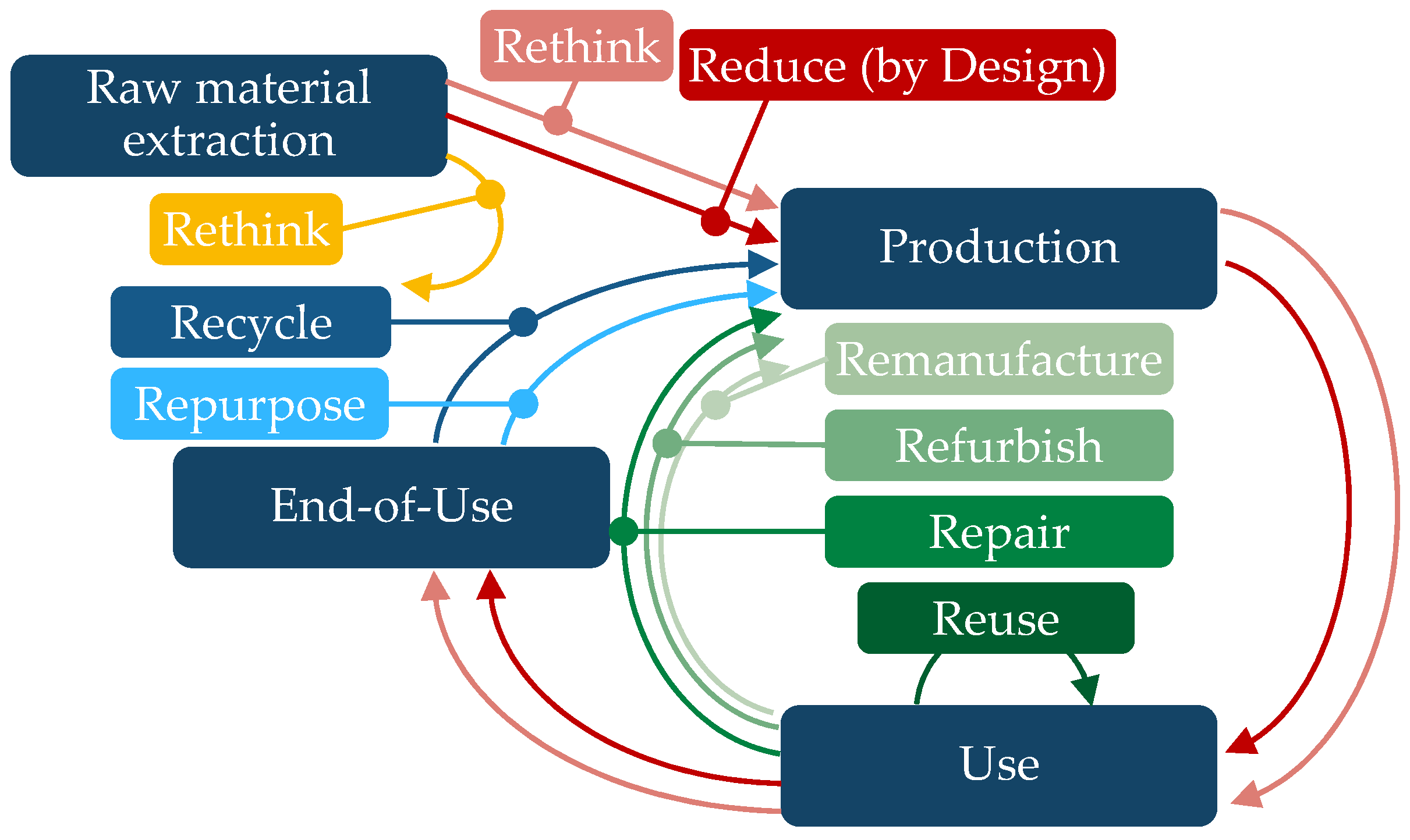
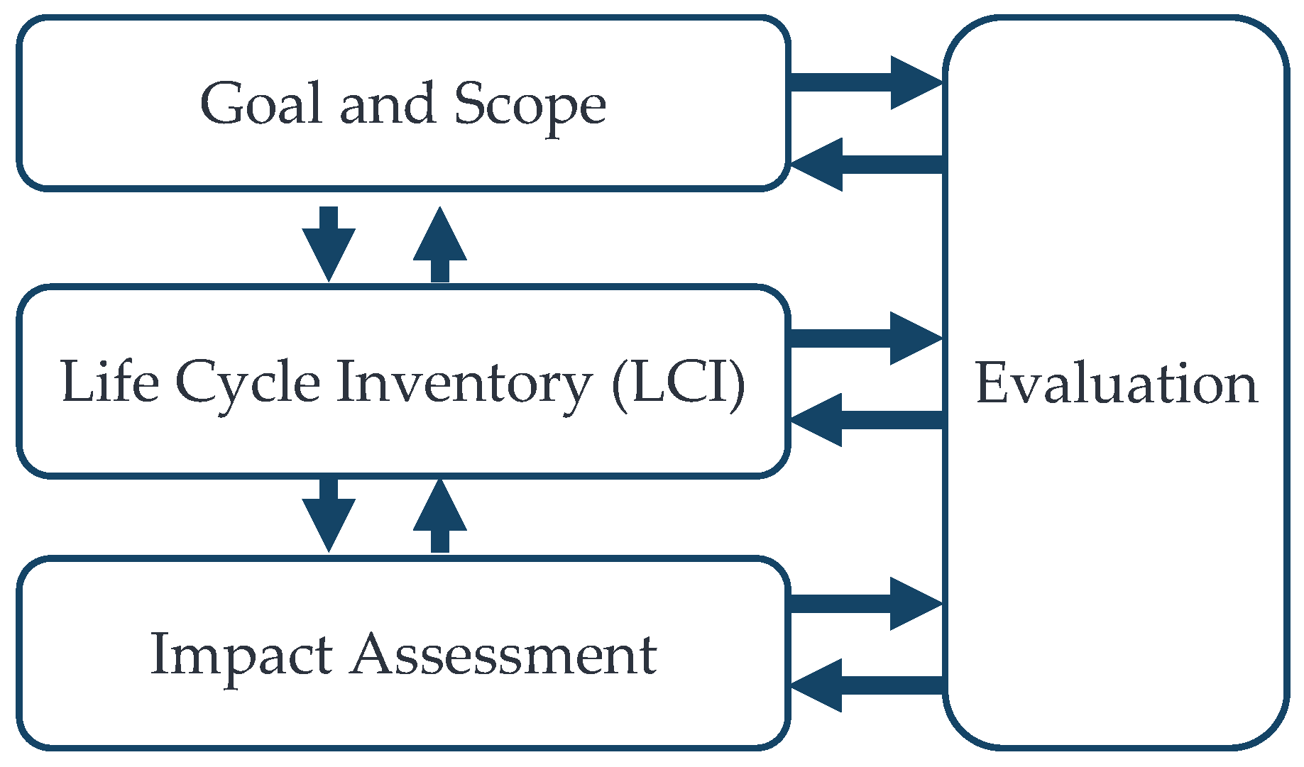
2.1. Lifecycle of a Product and Analyzing Methods

The lifecycle of a product can be described from various perspectives. This paper focuses on the ecological lifecycle, detailing its environmental impact throughout different phases. From an ecological point of view, the product lifecycle is divided into the phases of raw material extraction, production, assembly, packaging and distribution, use and End-of-Use [34]. The main steps, i.e., raw material, production, usage and End-of-Use are visualized in Figure 2.
Each phase has its own ecological impact. At the End-of-Use phase, various strategies can be employed to reintegrate components into the lifecycle of the next generation. But also, this lifecycle phase has its impact and is influenced by the design of the electric traction motor as well as the used equipment for the processes at the End-of-Use. It is similar to the emissions during the production phase, where the energy consumption and the needed material are defined by the component design and the selected manufacturing process, as well as through the used production equipment. This interdependencies between the product and the production equipment are described by the cross model of the product and production lifecycle [35].
An additional challenge during the product development is the interaction of different component manufacturer which need to be capable of sharing information regarding sustainability. To account for the ecological impact of the lifecycle phases, the LCA, which is separated into four phases, can be used. The phases of an LCA are shown in Figure 3.
First, the goal and scope of the study are defined. This includes the definition of the product system and the functional unit for the LCA. The product system is the summary of process modules, elementary flows and product flows along the lifecycle of a product to fulfill a determined function. The definition of the functional unit of the product system is also important. For a reliable comparison of two product systems, it is crucial that they fulfill the same functions. In the context of an electric traction motor this could be the supply of a specific power. The definition of the goal of the study defines the required level of detail. With the scope of the LCA it is defined which lifecycle phases are considered in the assessment [20].
This phase is followed by the Life Cycle Inventory (LCI). During this phase, all in- and output flows of the process modules in the product system are determined. The modeled flows depend on the type of process module. The process module can be a manufacturing process or a usage process, for example. The size of the input and output flows depends on the design decisions made and the machines used. For modeling these flows, different approaches can be used like system simulation approaches for energy consumption or the use of commercial databases like ecoinvent, which includes the elementary flows of different processes and materials. The results from the inventory analysis are the input for the impact assessment phase. The results from the LCI are assigned to the selected impact assessment categories, and the impact assessment indicators are calculated. Due to the different units of the indicators, it is necessary to normalize them for comparison. The last step of an LCA is the evaluation of the results [20].
To analyze costs over the lifecycle, the LCC is a common approach. In [24], the methodology for LCC is described. The guideline describes the lifecycle costs from a user perspective. The costs are separated into investment cost, usage cost and disposal cost. From the perspective of a manufacturing company of electric traction motors, the costs can be categorized into development costs, manufacturing costs, usage costs and disposal costs. Although the manufacturing company does not incur the costs of use specifically, it is the company’s goal to manufacture a product that is as cost-effective as possible during usage. For this purpose, it is required to integrate these costs in the evaluation of solutions. The investment costs for the customer are directly affected by the development and manufacturing costs of the manufacturer. Therefore, it is the goal of the manufacturer to reduce the development and manufacturing cost, and integrate this in the LCC from the manufacturer’s perspective. For calculating the manufacturing cost in the LCC model, the material flow cost accounting can be used. It separates the manufacturing costs in production costs and material costs. The production cost is further separated into indirect cost, like machine cost and labor cost, and direct cost, like energy cost [36]. To determine the production costs based on product information, several approaches are presented in the literature [37].
To compare different solutions, an overall sustainability index is required. The index is calculated with the results from LCA and LCC. The analyzed product is separated in its subsystems and components similar to the hierarchical functional structure of a product. This allows for calculating the index for specific subsystems or the whole system [38]. The index itself is structured with the Analytical Hierarchy Process (AHP), which allows a user specific weighting of the indicators [39]. To find the best trade-off between the evaluation criteria, different multi-criteria decision-making methods can be applied.
To sum up, the lifecycle of an electric traction motor includes several stakeholders and the emerging cost, and environmental impact is defined during product design. For this purpose, the integration of an evaluation model in the development phase is required which is based on LCA and LCC. The main challenge to overcome is the lack of information about the product itself and the behavior in the lifecycle phases during development. To overcome this challenge a systematic development approach in combination with suitable models and databases is needed.

2.2. Development Approaches

Traditional development approaches include VDI 2221 [40] and VDI 2206 [41]. The focus of VDI 2221 is a structured process for problem solving which divides development starting from the requirements and functions into individual modules. The defined modules are then further detailed. The process lacks guidance for a systematic cross-lifecycle and cross-module evaluation from an economic and ecological perspective. Overcoming the missing systematic evaluation of ecological impact, Kupfer et al. extended the process with an ecological perspective [42]. For each development step, specific process steps for implementing an LCA along the process were added. However, the process has no guideline to generate the models and interconnections between the modules to enable optimization of the lifecycle phases and module borders.
VDI 2206 addresses the interconnection between systems, subsystems and components of a product. The process is modeled as “V”. On the left side, the system is decomposed to subsystems and components which are developed with an increased level of detail. On the right side of “V”, the components and subsystems are integrated again. It recommends an iterative process with several runs through “V”. Furthermore, the production system should be developed in a parallel “V” [41]. Although the guideline provides for the early integration of production into product development and recommends the integration of MBSE, a structured description of the product and a link between the models are missing. In addition, a higher-level evaluation model is missing. Scholz et al. presented an adaption of the V-model with the goal to increase the usage of lightweight potentials [43]. The model has three parallel lines of development. These are the product, the production and the material. Decisions during the development are continuously made in the target conflict of these three domains. The backbone of the model is the MBSE approach, which interconnects the different domains of the model.
The product is structured with the RFLP approach. The approach describes the product on four levels: requirements (R), functional (F), logical (L) and physical (P). With “R” and “F”, the needs of the product are described. In “L”, solution principles are selected which are detailed in “P”. This approach is expanded by a technical description (T) to reduce the gap between logical and physical description with describing the components first with rough installation space and geometry parameters before starting with the final itemization in “P”.
Parallel to the development, simulation models and optimization strategies are developed. As a very important aspect, the integration of data from previous projects for evaluations was identified. The structured development process results in a systematic product description from the system perspective, over the subsystem perspective up to the component perspective [43].
As a software tool to model a product based on the expanded approach, Capella V6.0.0 was used in a case study [44]. Capella is an MBSE tool for designing system architectures. The methodology of the system is based on the ARCADIA method. The ARCADIA method defines two major areas of activity requirements analysis: requirement modeling and architecture design. This enables the handling of complex systems and through the usage of different viewpoints, the whole lifecycle can be modeled [45].
To enable the continuous evaluation during the development process, the production as well as the material needs to be detailed in parallel to the product development. Sinnwell and Krenkel et al. identified the need for a common modeling language for product and production development [46]. The authors provide a systematic development approach for product and production system development, with a detailed methodology for conceptual manufacturing systems design in the early development phase. For this purpose, the manufacturing system is described in the requirement level, the technique and material flow level, the dimensioning and structure level, and the technical solution level. In each level of detail, the manufacturing system is described in these four levels in dependence to the product development. For the common description language, a UML-based modeling approach is used. The approach supports engineers in communication in the early phase of product development. However, the approach lacks interconnection models to evaluate solutions to find the best overall solution from an economic and ecological perspective over the whole lifecycle. Nevertheless, the approach shows create opportunities in extending the description to the manufacturing processes regarding End-of-Use processes in a circular economy and the connection with an overall evaluation model.
To sum up, using a systematic development approach presented in [43] supports in separating the system in subsystems and components, but results in a standardized description which helps to evaluate solutions and assign data from previous developments. Furthermore, describing the development of the production system as well as the planning of End-of-Use show great potential for developing a cross-component and cross-lifecycle phase economic and ecological optimized electric traction motor. To enable the evaluation, the necessary simulation models as well as the connection to information from previous development phases need to be further detailed.

2.3. Digital Twin in Manufacturing and Product Development

The term ‘digital twin’ is used in many contexts. Furthermore, in the literature are many definitions of digital twins. The definition in this paper is oriented on the definition by Stark et al. [47]. They distinguish between the digital master and the digital shadow, which, together, make up a digital twin. The digital master is the resulting digital prototype of the product or production system through the product or production system development. During the production, usage and End-of-Use of a product or production system, a lot of data are generated which are described as the digital shadow. They represent the product in the real world. Linking the digital master and the digital shadow through algorithms or simulation models results in a digital twin [47].
This clearly shows the importance of systematic model-based product development in order to have a digital twin for later generations of development. The digital master created during product development must match the digital shadow created in later lifecycle phases.
To optimize products, digital twins can be used for different purposes. Through coupling a digital twin with the ERP and MES, decisions in manufacturing planning can be made faster and with better information. In the product design, information from earlier product generations can be used to identify the customer requirements and validate the product with situations from reality [33].
Tao et al. present a framework for the digital twin-driven development [48]. The framework proposes five steps of development in accordance with Pahl et al. [49]. The main steps are planning and task clarification, conceptual design, embodiment design, detail design and virtual verification [49]. Two V-models are run through the development steps. The main development “V” is accompanied in parallel by the “V” of the digital twin [48]. However, the framework assumes that a digital twin already exists and does not address the design of product development in such a way that models can continue to be used. Furthermore, information regarding materials and manufacturing is integrated late in the development.
Lo and Chen et al. describe the increasing advantage of digital twins with an increasing amount of product generations [50]. Through connecting the information of similar products, the database for the digital twin increases and better information can be provided for product development.
For generating a digital twin, the data source needs to be developed. This can involve integrating specific sensors to generate data for a process step. The generated data need to be transferred into a storage system which is able to manage the data. These data should be processed through big data technology to reduce the amount of data. Afterward, the results are visualized through charts and graphs [51]. The steps enable the monitoring of the product during the lifecycle phase measurement. However, it does not provide a concept integrating the data in previous lifecycle stages like development.
Arnemann and Winter et al. developed an information model to integrate data in earlier lifecycle phases [52]. Based on service cases, which are concrete use cases of data in product design, the data generated during the lifecycle of previous product generations are structured for the product designer. In the case of applying an LCA and LCC, the information model would provide the relevant data for the calculation. But an implementation of this case is not provided yet. Furthermore, integration in a systematic development process which provides a proper description of the product to identify similar products in data storage is not provided.
In summary, the digital twin shows great potential during the product design. There are already existing approaches to integrate the digital twin in product development but with a focus on the usage phase. The application of the digital twin regarding manufacturing focuses on predictive maintenance and production planning. However, for an integrated evaluation during product development from an economic, ecological and functional perspective, a digital twin that is available over the whole product lifecycle is necessary. Bringing the information in earlier lifecycle phases than they are generated is a key factor here. Furthermore, a standardized and systematic description of the product over the whole lifecycle is required. Additionally, a common description from the different perspectives of raw material extraction, manufacturing, usage, and End-of-Use is required during product development.

3. Methodology

This section describes the requirements of a cross-lifecycle development approach and presents the derived methodology. Afterward, application in an example of an electric traction motor is presented.

3.1. Methodology Requirements

Based on the literature of the previous section, the requirements of a cross-lifecycle development approach can be determined. The main goal of each development process should be to fulfill the external requirements. These are customer requirements, political requirements or even company-specific requirements like the usage of existing machines or suppliers. In addition to the hard requirements that must be met, there are also soft requirements that must be optimized in the target-size conflict. The economic and ecological sustainability is part of these requirements. Therefore, it is necessary to consider the whole lifecycle during development to overcome local optima which do not lead to a global optimum. This requires the evaluation of solutions using an evaluation model that considers the entire product lifecycle. To carry out an evaluation from the perspective of the individual phases of the product lifecycle, suitable models and information are required. Due to the lack of knowledge regarding the developed product, data from previous product generations are required to create a digital twin. In accordance with the presented understanding of a digital twin in this paper, a uniform description of the product is required to build up the digital twin. Furthermore, the uniform description format in combination with defined interfaces between development stages and perspectives of the lifecycle is crucial for the cross-lifecycle evaluation of the product during development. In addition, concurrent engineering and fast decision-making need to be supported to decrease the time to the start of production and the time to market.

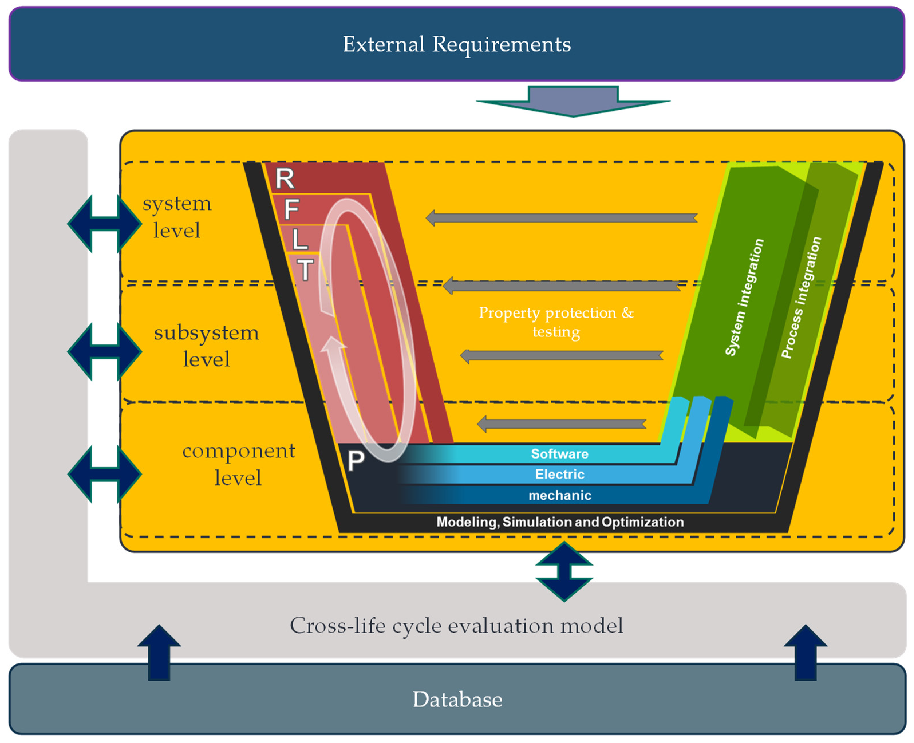
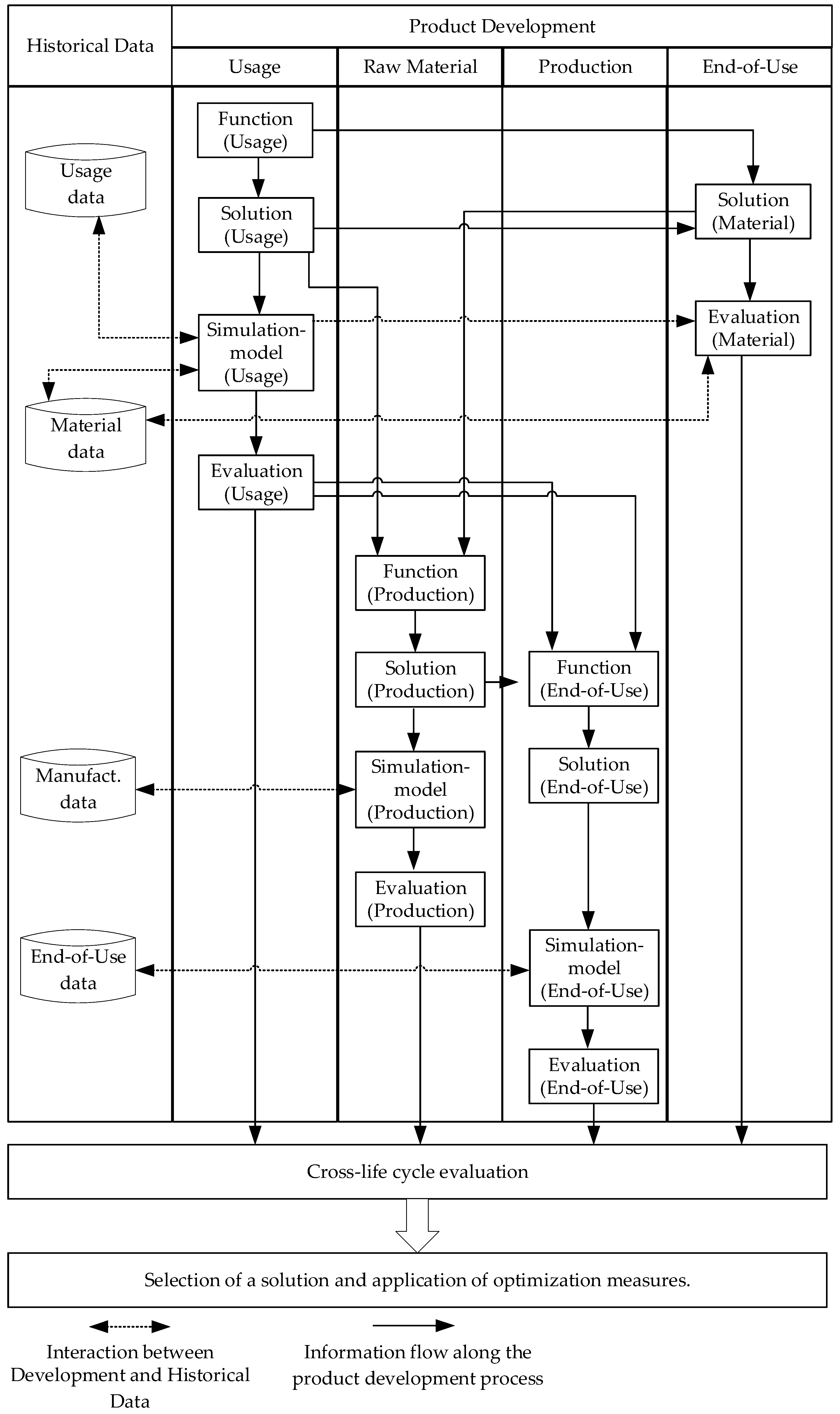
3.2. Cross-Lifecycle Development Approach

Based on the summarized requirements above, a cross-lifecycle development approach was derived. In accordance with the presented information, product lifecycle after the product development the lifecycle phases can be modeled in a ring as perspectives on the product. The ring is enclosed by a cross-lifecycle evaluation model. A database including data from previous product generations, as well as material data and manufacturing data is the base of the development model. The whole model is presented in Figure 4.
Each lifecycle perspective is affected by external requirements, for example, legal regulations regarding raw material extraction or possible manufacturing technologies from the manufacturing perspective. For the development process, it is necessary to translate the external requirements into boundary conditions. This needs to be carried out by each perspective. The perspective-specific boundary conditions will lead during the development to further boundaries in other perspectives. For example, if a specific manufacturing process is required through external requirements which cannot process a specific material, the material is not usable in this case.
To evaluate the design from different perspectives, solutions for the lifecycle phases on different detail levels need to be generated. In the development model, the usage perspective is equal to the conventional development approach to fulfill the requirements during usage. The level of detail in the manufacturing perspective is dependent on the included information from the usage perspective.
To enable the communication between the perspectives, a common modeling approach is required. The lifecycle is modeled as a closed loop to visualize the common description model over the whole product engineering process. According to the R, F, L, T, P approach in the adjusted V-model, each of the perspectives is described in this structure. Based on the generated information, the evaluation model is filled with information from of the perspective to get a cross-lifecycle evaluation. In Figure 5, the model is sliced in the manufacturing perspective. It describes the development process from the manufacturing perspective, including the interaction with the evaluation model and the database on different levels of detail.
The different levels along the V-model describe the level of detail. From a manufacturing perspective, the system is divided from the overall manufacturing concept on the system level to several manufacturing cells on the subsystem level and the machines and tools on the component level. With the increasing level of detail, the uncertainty in the evaluation model is reduced. The interaction of the perspectives is possible in both ways. The manufacturing perspective can provide requirements for the usage perspective regarding the limitations of manufacturing processes. In the other direction, the usage perspective provides requirements regarding manufacturing to the manufacturing perspective, and proper processes and machines need to be selected, evaluated and integrated in the evaluation model. Through the connection of all lifecycle phases over one description model interdependencies can be identified easily. To evaluate the impact of the End-of-Use, the development in this perspective needs to be carried out similarly to the manufacturing perspective. Solutions for the End-of-Use strategy need to be developed and described in models for interaction with the evaluation model and the analysis of the impact on other lifecycle phases.
Figure 6 shows the structure of the cross-lifecycle evaluation model for a sustainable electric traction motor.
Based on the AHP, the evaluation model can be structured in three main indicators. These are the economic indicator, the ecological indicator and the technical indicator. These main indicators are further detailed in more specific indicators. The structure of the economic indicator is based on the LCC. It can be further separated in the costs per life-cycle phase, which need to be determined with phase-specific models.
The ecological indicator is defined in accordance with the LCA. It is described by the relevant impact categories. The examples in Figure 6 are midpoint-impact categories which describe the potential impact on the environment; these can be calculated with less assumptions than the endpoint-impact categories. Endpoint-impact categories describe the real impact on the environment.
The third indicator, the technical indicator, is described by functional indicators which are not directly included in the other two indicators. The units of the sub-indicators are all different. Through this, the indicators cannot be compared directly with one number. It is necessary to apply multi-criteria decision-making methods for decision making based on the evaluation model which is able to handle different units of the evaluation criteria. Nevertheless, generating the information to calculate the sub-indicators is a huge challenge considering the missing information during product development.
Based on the previously described methodology, a more detailed view of the whole approach is presented in Figure 7.
Starting with the usage perspective of an electric traction motor, the motor is described with the required functions. With this, the required behavior of the motor during usage is defined. Based on this description of the motor, a solution on a logical level which describes the solution principles of the motor is generated. In the following technical level, the solution principles are described by geometrical parameters like part volume, material and geometry. Furthermore, the electrical parameters are defined. This can be performed in several iterations. The solutions for the system, subsystem and components of the developed electric traction motor are detailed enough to determine the required functions from a raw material and production perspective. Similar to the usage perspective, the solutions for these perspectives are developed. Using the same structure and a similar description model which is based on a functional description in the beginning supports the interconnection between the perspectives. Due to this fact, the End-of-Use strategies are affected by the solution from the usage perspective, as well as the raw material and production solution; the functions from these perspectives are determined after the raw material and production perspective.
The linking of perspectives by means of the functional description makes it possible to identify changes along the product development process across perspectives. Furthermore, the longer the development time, the more the model of the product grows.
Based on the generated solutions in the different perspectives, simulation models need to be created to evaluate the respective phase of the lifecycle. For the usage perspective, energy consumption and maintenance are important for the economic and ecological evaluation of the electric traction motor. Based on the functions and data from previous generations, scenarios for the usage need to be defined to simulate the motor in combination with the battery and the car. This allows for evaluating the impact of lightweight design on energy consumption and maintenance from an economic and ecological perspective. To calculate the economic and ecological sub-indicators, the simulation needs to be connected with database, including costs and environmental impact of energy usage. Furthermore, thermal effects and forces need to be analyzed, making sure the motor fulfills the requirements. The results of the simulation are affected by the used materials. To evaluate the impact of the materials which are selected in combination with the defined requirements and functions from the usage phase, the economic and ecological perspective of the materials is based on the required amount of the material which is dependent on the used manufacturing process and a material database, including the elementary flows for the LCI and impact assessment from an ecological point of view, as well as the costs per amount from an economic point of view.
In the production phase, two aspects need to be considered. The first one deals with the processes and the other one considers the resources. Depending on the required detail of the evaluation, the two aspects can be modeled with different levels of detail. If just a first rough evaluation is required, the required processes can be selected based on the functions as the solution and the sub-indicators can be calculated based on historical data. For a more detailed evaluation, resources like machines and tools need to be selected or designed to combine the process model with the research model and get a detailed evaluation of the manufacturing process. For evaluating the energy consumption of a machine, the physic-based simulation shows great potential in the literature. The processes can be modeled by Finite Element Analysis. The database needs to include historical process parameters, machines and tools to enable a fast evaluation. Furthermore, the environmental impact of energy consumption and used additional materials, as well as the cost impact need to be included.
Beside the evaluation of the developed product design, the simulation models of the process, machine and tool can be used to enable a fast ramp-up of the product and decrease the time from development to the start of production.
The modeling of the End-of-Use of the motor is very similar to the production. Depending on the chosen R-strategy at the End-of-Use stage, historical data for recycling can be used or the processes and resources can be modeled similar to the production phase. The disassembly processes can be described by specific process parameters like in production. To realize the processes, machines and tools are required which can be modeled with physic-based simulation to analyze the energy consumption.
When evaluating production and End-of-Use, it is important to consider not only the costs and environmental impacts that arise during this phase, but also to include the necessary investment costs for new tools and machines in the analysis.
The evaluation from the different perspectives is integrated into the cross-lifecycle evaluation model. If different variants are generated, the best possible system solution consisting of usage, material, production and End-of-Life can be selected by the application of a multi-criteria decision-making method like Technique for Order Preference by Similarity to Ideal Solution (TOPSIS).
If one solution is selected which needs to be further detailed or just one solution was generated, optimization measures from the different perspectives can be identified with the evaluation model as well.

4. Results

This section presents the application of the methodology on the example of the development of an electric traction motor. The electric traction motor functions by converting electrical energy from an energy storage system into kinetic energy, enabling motion. This energy conversion is achieved through the generation of rotational movement, driven by interactions such as the attraction between magnetic poles of opposite polarity, electrostatic forces, or piezoelectric effects. Structurally, an electric traction motor is composed of four key components: stator, rotor, housing, and the transmission system [10,53].
In automotive applications, interior permanent magnet (IPM) motors are widely adopted due to their superior performance at high rotational speeds, often exceeding 15,000 rpm. The rotor in an IPM motor typically consists of 3–8 lamination stacks, housing numerous magnets arranged in specific patterns. The stator winding is mostly made of rectangular copper wire that are bent to so-called hairpins. IPMs are renowned for their high-reluctance torque, excellent efficiency, superior power factor, minimal heat generation, compact size, and low noise levels. These characteristics make them particularly well-suited for demanding applications. The advancement and affordability of modern power electronics have further solidified IPMs as the leading choice in electric traction motor applications [54].
Furthermore, the study underlines the central role of the End-of-Use phase in shaping the overall techno-economic and environmental sustainability. In the following section, the methodology introduced in Section 3 is applied to the context of the electric traction motor to further explore these findings. The methodology presented above is now implemented in the software Capella.
First, the external requirements were analyzed for this purpose. In the requirements engineering the external requirements were translated to the requirements of the product from the different perspectives. Table 1 shows the relevant requirements for the electric traction motor from the usage perspective.
The presented parameters are all necessary for describing the electric traction motor and can be understood as a minimal list of requirements. Initially, the parameters were categorized according to hierarchy levels. The parameters in the first column all refer to the system level and thus the electric motor as a whole system. Based on the system level, the requirements of the subsystems are determined. These requirements are documented in the third column and are assigned to the subsystems “rotor” and “stator”.
The subsystems are created based on the functional description of electric traction motor, which is visualized in Figure 8.
The product structure, including the system, subsystem and components, is shown in blue. For example, the subsystem rotor consists of the components “magnet”, “magnet fixation”, “rotor lamination stack”, “rotor shaft” and “balancing equipment”. The physical interrelationship between the individual components is represented by the connecting lines. Furthermore, the interaction with other subsystems of the whole system car is visualized. This provides the framework for modeling the use phase. Additionally, the figure highlights the functions of the individual components in green. For instance, the function of the magnet is to provide a magnetic field, while the function of the magnet fixation is to secure the magnet.
Subsequently, the components of the rotor are described at a technical level by geometrical and physical parameters. Table 2 shows the parameters that describe the rotor.
In addition to the product description, a description of the phases in the product lifecycle, as outlined in Figure 8, is also required. For demonstration purposes, the End-of-Use state is examined in greater detail here. All other descriptions must also be implemented in this manner to ensure a complete depiction. The necessary disassembly processes are illustrated in Figure 9.
For the disassembly process, it must first be analyzed up to which hierarchy level a potential disassembly is possible and meaningful. Previous studies indicate that, due to the high material value, the recovery of magnets is particularly effective for electric traction motors. Therefore, the rotor must be disassembled to the point where the individual magnets are exposed and can be pressed out [55]. Heim et al. developed an automated disassembly station that enables the removal of magnets from the lamination stack. First, the rotor is demagnetized, followed by the removal of the bearings. Subsequently, the lamination stack is pressed out, and the axial fixation is removed. If the rotor consists of separate lamination stacks, they are divided into individual stacks, exposing the magnets. Finally, the magnets can be removed using a stamping tool in the magnet disassembly station [55].
Based on a similar description of the production phase, the necessary processes can be determined based on the functions. Figure 10 shows the required processes for the subsystem rotor and stator which are assembled into the system electric traction motor at the end of the production.
At the initial stage of production, both stator and rotor manufacturing necessitate a lamination stack, typically fabricated from electrical steel via a mother–child punching process, followed by a precise stacking operation. During stator fabrication, the slots of the stator lamination stack are first lined with a paper-based insulation material. Subsequently, hairpins are inserted into these insulated slots. This involves shaping rectangular copper wires into the required hairpin geometry through a specialized hairpin-forming process. The installed hairpins feature a bent configuration on the upper side, while the lower ends must be spread and twisted through a dedicated twisting process. This twisting is crucial for enabling the electrical connection of hairpins belonging to the same three-phase winding in subsequent operations. These windings are completed using a laser welding process, where the three distinct phases of the three-phase motor are established. The process proceeds with the installation of the connection assembly, followed by an impregnation and insulation treatment. To ensure quality and functionality, the stator undergoes rigorous end-of-line testing [54,56].
The rotor manufacturing process for IPMs begins with the assembly of the magnets. Here, magnets are precisely positioned within the rotor lamination stack and subsequently secured. Depending on the specific production methodology, this securing process can involve transfer molding, adhesive bonding, or mechanical crimping. The individual stacks are then aligned and assembled onto the rotor shaft. A balancing process follows, wherein any residual imbalances are minimized to achieve the required balance quality. Peripheral components such as speed sensors and bearings are also integrated at this stage, and the rotor undergoes a magnetization procedure. Similar to the stator, the rotor production concludes with a comprehensive end-of-line evaluation to validate its performance and adherence to specifications.
The final assembly involves integrating the two active components—the stator and rotor—into a unified motor system. The rotor is inserted into the stator, the stator is press-fitted into the motor housing, and the rotor is precisely mounted within the housing. Additional components, including the gearbox, differential and power electronics, are then affixed. The manufacturing process culminates in a final end-of-line test, where the complete motor assembly is evaluated under operational conditions for the first time and approved for deployment [8].
The described production processes are affected by lots of parameters which are defined during product development or process design. It becomes evident that numerous manufacturing steps have a significant impact on the quality of the electric traction motor. Additionally, the execution of these processes critically influences the techno-economic and environmental sustainability of the system. For this purpose, it is crucial to record the parameters and store them in an information model. Furthermore, there are complex processes like the hairpin coil bending, which requires lots of effort to define the correct process parameters [56,57].
In particular, the design determined during the early stages exhibits a substantial variability in sustainability outcomes. Klein et al. demonstrated this effect by comparing a standard rotor, commonly used in vehicles, with a lightweight rotor design [58]. As an example, the assembly process of the magnets to the rotor was used. The resulting functional description is visualized in Figure 11.
On the right side, the lamination stack is designed with spring noses, which press the magnets against the lamination stack. For this reason, the magnets just need to be assembled to the lamination stack with no thermal processes. On the left side, the lamination stack does not have this spring noses. Therefore, a chemical process is needed to fix the magnets in place and close the gap between the magnet and the lamination stack. The functional diagram shows that heat is required during assembly, indicating high energy consumption. For a first rough comparison, it is possible to use historical data for the transfer molding process, which can be easily identified through the systematic description. For the assembly with spring nose, all the unnecessary functions can be ignored for the evaluation. From the previous functional description, the following analysis framework in Figure 12 can be determined.
Based on this framework, the design decision can be made based on the ecological criteria in Table 3.
For the evaluation, measured data and ecoinvent 3.9.1 data were combined. The impacts were calculated with the CML v4.8 2016 assessment method.
Through the different units, the criteria need to be normalized and weighted for decision making. All of the criteria have the goal to be minimized. In the Table 3, it is clear that the lightweight rotor is the better solution in all criteria. Hence, the result of the multi-criteria evaluation model will be the selection of the lightweight rotor.

5. Discussion

To overcome the challenges of sustainability during the development of electric traction motors, this paper presents a systematic approach which enables the consideration of the whole lifecycle during the product development. The integration of a digital twin in the development process was identified as a key factor in the development process. For this purpose, a systematic development model considering the perspectives of the four main lifecycle phases was presented. All of the perspectives are using a similar structure and description of the solutions, which facilitates the cross-linking of the different perspectives during product development. Through this, it is possible to generate perspective-specific solutions for a specific product design, and integrate this into the evaluation model. Considering economic, ecological and technical parameters in the evaluation model avoids the generation of local optimums regarding sustainability. Furthermore, through the cross-linking of every lifecycle phase in the evaluation model, no local optimums over the lifecycle are generated. The information regarding the evaluation criteria can be generated by a combination of digital twin and external databases. The benefit of using the digital twin lies in better and more realistic data quality compared to external databases. These are very helpful for adding information like the carbon footprint of energy consumption. Beside the evaluation of solutions and the simplification of the communication between the lifecycle phases during product design, the approach also provides a better understanding regarding interdependencies between subsystems and components, as well as between the lifecycle phases.
The analysis of the lifecycle of an electric traction motor identified a large number of measurable parameters. Starting with an electric traction motor, the modeling was implemented using Capella. Using the example of the rotor, a possible solution for the End-of-Use of the magnets was modeled in the logical design. Through the description of the End-of-Use process based on functions and logical elements the expert for this lifecycle phase can provide fast and easy to understand information regarding required efforts for the End-of-Use in case of a design decision. Through a connection with historical data of digital twin, a first rough evaluation can be made with this information. If it is further detailed, the data quality of the design increases and the quality of the evaluation improves.
Based on technical parameter of the rotor from the usage perspective two cases for the production phase were modelled in the logical view. It shows the impact of the product design to the manufacturing processes as well as the importance of the systematic modeling. Even with the rough description in the logical level, it can be figured out which components of the processes need to be considered and which can be ignored. Furthermore, a first analysis regarding the economic, ecological and technical evaluation can be made through the descriptions. This avoids the need to work out several solutions in detail or to run several revision loops later on. In traditional development processes, revision loops often result from the fact that insufficient information is available in the early stages and therefore a development path is initially taken on the basis of inadequate data. Additionally, through the standardized description, information from previous generations can be categorized to the correct functions. The comparison of the two variants clearly shows the potential of the methodology through efficient quantitative evaluations from different perspectives ad with different criteria.
Although the methodology offers long-term advantages in terms of decision-making and shorter development times, it initially requires a great deal of effort to implement the procedure within an organization. Furthermore, the existing manufacturing equipment needs to be equipped with sensors and tools to be able to provide the relevant data and it is required to have already electric traction motors in use which are developed with the similar procedure and provide the correct data. To handle all the data, a suitable data handling structure is required. The potential of the approach is clearly shown but for the implementation a consistent application with the suitable infrastructure is required to show its full potential.
In this paper, the focus is on electric traction motors because of their relevance for the electric mobility and the high quantities in production. This leads to a higher importance of production development. But the approach can be applied to other industries like electric generator manufacturing as well. However, the integration of the production and End-of-Use will be different. Due to lower quantities, existing manufacturing equipment is used instead of doing a detailed line planning for a new electric traction motor.

6. Conclusions

This paper presents a methodology to consider the whole lifecycle of an electric traction motor during product development. To enable a quantitative evaluation based on the presented cross-lifecycle evaluation model, the digital twin in several lifecycle phases is integrated in the development process to predict the behavior and the economic and ecological impact. Using a similar and standardized description for all the perspectives of lifecycle phases in the development process supports the interoperability between the perspectives and the alignment of data from previous product generations.
Nevertheless, based on this approach, further research needs to be carried out, building a holistic and interconnected tool chain to develop electric traction motors. In the presented approach, the description of the solutions needs to be carried out by expert knowledge. The goal should be to generate the solutions in the lifecycle phases based on the description for the usage phase. Therefore, an important aspect will be the integration of automated process planning tools which are able to generate the functional structure of production and End-of-Use based on the information of the product. Furthermore, the next step is to describe the interdependencies not just in one direction, but as an integrated parametrized optimization model which is able to find the overall best solution in a predefined solutions space.

Author Contributions

Conceptualization, J.S. and N.K.; methodology, J.S. and N.K.; validation, J.S. and N.K.; writing—original draft preparation, J.S. and N.K.; writing—review and editing, F.K. and J.F.; visualization, J.S. and N.K.; supervision, F.K. and J.F. All authors have read and agreed to the published version of the manuscript.

Funding

This research received no external funding.

Institutional Review Board Statement

Not applicable.

Informed Consent Statement

Not applicable.

Data Availability Statement

The original contributions presented in this study are included in the article. Further inquiries can be directed to the corresponding author.

Conflicts of Interest

The authors declare no conflicts of interest.

References

  1. United Nations. Sustainable Development Goals. Available online: https://sdgs.un.org/ (accessed on 10 May 2024).
  2. Europäische Komission. Der Europäische Grüne Deal. Available online: https://eur-lex.europa.eu/resource.html?uri=cellar:b828d165-1c22-11ea-8c1f-01aa75ed71a1.0021.02/DOC_2&format=PDF (accessed on 31 October 2024).
  3. European Commission. ‘Fit for 55’: Delivering the EU’s 2030 Climate Target on the Way to Climate Neutrality. Available online: https://eur-lex.europa.eu/legal-content/EN/TXT/PDF/?uri=CELEX:52021DC0550&from=DE (accessed on 31 July 2021).
  4. Elkington, J. The triple bottom line. Environ. Manag. Read. Cases 1997, 2, 49–66. [Google Scholar]
  5. DeStatis—Statistisches Bundesamt. Europäischer Green Deal: Klimaneutralität bis 2050. Available online: https://www.destatis.de/Europa/DE/Thema/GreenDeal/GreenDeal.html#798700 (accessed on 31 October 2024).
  6. Zhang, X.; Xu, Z.; Gerada, C.; Gerada, D. Carbon Emission Analysis of Electrical Machines. In Proceedings of the 2021 24th International Conference on Electrical Machines and Systems (ICEMS), Gyeongju, Republic of Korea, 31 October–3 November 2021; IEEE: Piscataway, NJ, USA, 2021; pp. 1678–1683, ISBN 978-8-9865-1021-8. [Google Scholar]
  7. Linder, M.; Nauclér, T.; Nekovar, S.; Pfeiffer, A.; Vekic, N. The Race to Decarbonize Electric-Vehicle Batteries. Available online: https://www.mckinsey.com/~/media/mckinsey/industries/automotive%20and%20assembly/our%20insights/the%20race%20to%20decarbonize%20electric%20vehicle%20batteries/the-race-to-decarbonize-electric-vehicle-batteries-vf.pdf?shouldIndex=false (accessed on 4 November 2023).
  8. Stanek, R.; Kirchen, J.; Klein, A.; Rupp, M.; Flemming, J.; Steiner, L.; Knecht, T. Wertschöpfungspotenziale von E-Motoren für den Automobilbereich in Baden-Württemberg: Themenpapier Cluster Elektromobilität Süd-West; e-mobil BW GmbH-Landesagentur für neue Mobilitätslösungen und Automotive: Stuttgart, Germany, 2021. [Google Scholar]
  9. Qiao, Q.; Zhao, F.; Liu, Z.; Jiang, S.; Hao, H. Cradle-to-gate greenhouse gas emissions of battery electric and internal combustion engine vehicles in China. Appl. Energy 2017, 204, 1399–1411. [Google Scholar] [CrossRef]
  10. Tong, W. Mechanical Design and Manufacturing of Electric Motors, 2nd ed.; CRC Press Taylor & Francis Group: Boca Raton, FL, USA; London, UK; New York, NY, USA, 2022; ISBN 9781003097716. [Google Scholar]
  11. Doppelbauer, M. Introduction to Electromobility; Springer Fachmedien Wiesbaden: Wiesbaden, Germany, 2024; ISBN 978-3-658-45481-4. [Google Scholar]
  12. ISO 59004:2024-05; Circular Economy—Vocabulary, Principles and Guidance for Implementation. ISO: Geneva, Switzerland, 2024. Available online: https://www.dinmedia.de/de/norm/iso-59004/380983795 (accessed on 17 December 2024).
  13. Kirchherr, J.; Reike, D.; Hekkert, M. Conceptualizing the Circular Economy: An Analysis of 114 Definitions. Resour. Conserv. Recycl. 2017, 127, 221–232. [Google Scholar] [CrossRef]
  14. Wößner, W.; Gürbüz, H.; Heim, M.; Klein, N.; Schulz, J.; Fleischer, J. Federnde Rotorkomponenten für elektrische Antriebe. Z. Wirtsch. Fabr. 2022, 117, 667–672. [Google Scholar] [CrossRef]
  15. Potting, J.; Hekkert, M.; Worell, E.; Hanemaaijer, A. Circular Economy: Measuring Innovation in the Product Chain: Policy Report; PBL Netherlands Assessment Agency: The Hague, The Netherlands, 2017. [Google Scholar]
  16. Lanza, G.; Klenk, F.; Martin, M.; Brützel, O.; Hörsting, R. Sonderforschungsbereich 1574: Kreislauffabrik für das ewige innovative Produkt. Z. Wirtsch. Fabr. 2023, 118, 820–825. [Google Scholar] [CrossRef]
  17. Haynsworth, H.C.; Lyons, T. Remanufacturing by design, the missing link, 28th ed. Prod. Inventory Manag. 1987, 28, 24–29. [Google Scholar]
  18. Ehrlenspiel, K.; Kiewert, A.; Lindemann, U.; Mörtl, M. Kostengünstig Entwickeln und Konstruieren; Springer: Berlin/Heidelberg, Germany, 2014; ISBN 978-3-642-41958-4. [Google Scholar]
  19. Scholz, U.; Pastoors, S.; Becker, J.H.; Hofmann, D.; van Dun, R. (Eds.) Praxishandbuch Nachhaltige Produktentwicklung; Springer: Berlin/Heidelberg, Germany, 2018; ISBN 978-3-662-57319-8. [Google Scholar]
  20. DIN EN ISO 14040:2021-02; Umweltmanagement_-Ökobilanz_-Grundsätze und Rahmenbedingungen (ISO_14040:2006_+ Amd_1:2020); Deutsche Fassung EN_ISO_14040:2006_+ A1:2020. Beuth Verlag GmbH: Berlin, Germany, 2021.
  21. DIN EN ISO 14044:2021-02; Umweltmanagement_-Ökobilanz_-Anforderungen und Anleitungen (ISO_14044:2006_+ Amd_1:2017_+ Amd_2:2020); Deutsche Fassung EN_ISO_14044:2006_+ A1:2018_+ A2:2020. Beuth Verlag GmbH: Berlin, Germany, 2021.
  22. Auer, J.; Meincke, A. Comparative life cycle assessment of electric motors with different efficiency classes: A deep dive into the trade-offs between the life cycle stages in ecodesign context. Int. J. Life Cycle Assess. 2018, 23, 1590–1608. [Google Scholar] [CrossRef]
  23. Grosse Erdmann, J.; Mahr, A.; Derr, P.; Walczak, P.; Koller, J. Comparative Life Cycle Assessment of Conventionally Manufactured and Additive Remanufactured Electric Bicycle Motors; Publish-Ing: Hannover, Germany, 2023. [Google Scholar]
  24. DIN EN 60300-3-3:2005-03; Zuverlässigkeitsmanagement_-Teil_3-3: Anwendungsleitfaden_-Lebenszykluskosten (IEC_60300-3-3:2004); Deutsche Fassung EN_60300-3-3:2004. DIN Media GmbH: Berlin, Germany, 2005.
  25. Camargos, P.H.; da Costa, G.F.; Caetano, R.E. Determining the life cycle cost and reliability of an induction motor designed for light vehicle applications: A comparative analysis. Electr. Eng. 2022, 104, 2849–2858. [Google Scholar] [CrossRef]
  26. Dietz, T.; Pott, A.; Hägele, M.; Verl, A. A new, uncertainty-aware Cost-model for cost-benefit assessment of robot systems. In Proceedings of the IEEE ISR 2013, Seoul, Republic of Korea, 24–26 October 2013. [Google Scholar]
  27. Landscheidt, S.; Kans, M. Method for Assessing the Total Cost of Ownership of Industrial Robots. Procedia CIRP 2016, 57, 746–751. [Google Scholar] [CrossRef]
  28. Hoogmartens, R.; van Passel, S.; van Acker, K.; Dubois, M. Bridging the gap between LCA, LCC and CBA as sustainability assessment tools. Environ. Impact Assess. Rev. 2014, 48, 27–33. [Google Scholar] [CrossRef]
  29. Albers, A.; Bursac, N.; Wintergerst, E. Product generation development–importance and challenges from a design research perspective. New Dev. Mech. Mech. Eng. 2015, 13, 16–21. [Google Scholar]
  30. Scholz, J.; Zeidler, S.; Koessler, F.; Fleischer, J. Systematic Lightweight Design of Production Equipment with a Digital Toolchain. In Production at the Leading Edge of Technology; Bauernhansl, T., Verl, A., Liewald, M., Möhring, H.-C., Eds.; Springer: Cham, Switzerland, 2024; pp. 24–33. ISBN 978-3-031-47393-7. [Google Scholar]
  31. Kaspar, J.; König, K.; Scholz, J.; Quirin, S.; Kleiner, S.; Fleischer, J.; Herrmann, H.-G.; Vielhaber, M. SyProLei—A systematic product development process to exploit lightweight potentials while considering costs and CO2 emissions. Procedia CIRP 2022, 109, 520–525. [Google Scholar] [CrossRef]
  32. Albers, A.; Lanza, G.; Klippert, M.; Schäfer, L.; Frey, A.; Hellweg, F.; Müller-Welt, P.; Schöck, M.; Krahe, C.; Nowoseltschenko, K.; et al. Product-Production-CoDesign: An Approach on Integrated Product and Production Engineering Across Generations and Life Cycles. Procedia CIRP 2022, 109, 167–172. [Google Scholar] [CrossRef]
  33. Tao, F.; Cheng, J.; Qi, Q.; Zhang, M.; Zhang, H.; Sui, F. Digital twin-driven product design, manufacturing and service with big data. Int. J. Adv. Manuf. Technol. 2018, 94, 3563–3576. [Google Scholar] [CrossRef]
  34. van Doorsselaer, K.; Koopmans, R.J. Ecodesign; Carl Hanser Verlag GmbH & Co. KG: München, Germany, 2020; ISBN 978-1-56990-861-7. [Google Scholar]
  35. Westkämper, E. Zukunftsperspektiven der digitalen Produktion. In Digitale Produktion; Westkämper, E., Spath, D., Constantinescu, C., Lentes, J., Eds.; Springer: Berlin/Heidelberg, Germany, 2013; pp. 309–327. ISBN 978-3-642-20258-2. [Google Scholar]
  36. DIN EN ISO 14051:2011-12; Umweltmanagement—Materialflusskostenrechnung—Allgemeine Rahmenbedingungen (ISO 14051:2011); Deutsche und Englische Fassung EN ISO 14051:2011. Beuth Verlag GmbH: Berlin, Germany, 2011. [CrossRef]
  37. Niazi, A.; Dai, J.S.; Balabani, S.; Seneviratne, L. Product Cost Estimation: Technique Classification and Methodology Review. Int. J. Prod. Res. 2006, 128, 563–575. [Google Scholar] [CrossRef]
  38. Scholz, J.; Dilger, L.J.; Friedmann, M.; Fleischer, J. A Methodology for Sustainability Assessment and Decision Support for Sustainable Handling Systems. Procedia CIRP 2023, 116, 47–52. [Google Scholar] [CrossRef]
  39. Saaty, T.L. Time dependent decision-making; dynamic priorities in the AHP/ANP: Generalizing from points to functions and from real to complex variables. Math. Comput. Model. 2007, 46, 860–891. [Google Scholar] [CrossRef]
  40. Verein Deutscher Ingenieure. VDI-Richtlinie 2221 Blatt 1: Entwicklung Technischer Produkte und Systeme: Modell der Produktentwicklung; Beuth Verlag: Berlin, Germany, 2019; Available online: https://www.vdi.de/richtlinien/details/vdi-2221-blatt-1-entwicklung-technischer-produkte-und-systeme-modell-der-produktentwicklung (accessed on 31 October 2024).
  41. Verein Deutscher Ingenieure. VDI-Guidline 2206: Development of Mechatronic and Cyber-Physical Systems; Beuth Verlag: Berlin, Germany, 2021; Available online: https://www.vdi.de/en/home/vdi-standards/details/vdivde-2206-development-of-mechatronic-and-cyber-physical-systems (accessed on 31 October 2024).
  42. Kupfer, R.; Schilling, L.; Spitzer, S.; Zichner, M.; Gude, M. Neutral lightweight engineering: A holistic approach towards sustainability driven engineering. Discov. Sustain. 2022, 3, 1049. [Google Scholar] [CrossRef]
  43. Scholz, J.; Kaspar, J.; Quirin, S.; Kneidl, B.; Kleiner, S.; Friedmann, M.; Fleischer, J.; Herrmann, H.-G.; Vielhaber, M. Konzept eines systemischen Entwicklungsprozesses zur Hebung von Leichtbaupotenzialen. Z. Wirtsch. Fabr. 2021, 116, 797–800. [Google Scholar] [CrossRef]
  44. Scholz, J.; Kaspar, J.; König, K.; Friedmann, M.; Vielhaber, M.; Fleischer, J. Lightweight design of a gripping system using a holistic systematic development process—A case study. Procedia CIRP 2023, 118, 187–192. [Google Scholar] [CrossRef]
  45. Voirin, J.-L. Model-Based System and Architecture Engineering with the Arcadia Method; ISTE Press: London, UK; Kidlington, UK; Oxford, UK, 2018; ISBN 9780081017944. [Google Scholar]
  46. Sinnwell, C.; Krenkel, N.; Aurich, J.C. Conceptual manufacturing system design based on early product information. CIRP Ann. 2019, 68, 121–124. [Google Scholar] [CrossRef]
  47. Stark, R.; Kind, S.; Neumeyer, S. Innovations in digital modelling for next generation manufacturing system design. CIRP Ann. 2017, 66, 169–172. [Google Scholar] [CrossRef]
  48. Tao, F.; Sui, F.; Liu, A.; Qi, Q.; Zhang, M.; Song, B.; Guo, Z.; Lu, S.C.-Y.; Nee, A.Y.C. Digital twin-driven product design framework. Int. J. Prod. Res. 2019, 57, 3935–3953. [Google Scholar] [CrossRef]
  49. Pahl, G.; Beitz, W.; Feldhusen, J.; Grote, K.-H. Konstruktionslehre: Grundlagen Erfolgreicher Produktentwicklung; Methoden und Anwendung, 7th ed.; Springer: Berlin/Heidelberg, Germany, 2007; ISBN 978-3-540-34060-7. [Google Scholar]
  50. Lo, C.K.; Chen, C.H.; Zhong, R.Y. A review of digital twin in product design and development. Adv. Eng. Inform. 2021, 48, 101297. [Google Scholar] [CrossRef]
  51. Tao, F.; Qi, Q.; Liu, A.; Kusiak, A. Data-driven smart manufacturing. J. Manuf. Syst. 2018, 48, 157–169. [Google Scholar] [CrossRef]
  52. Arnemann, L.; Winter, S.; Quernheim, N.; Grieser, P.; Anderl, R.; Schleich, B. Information Model to Return Data of Digital Twins into Product Design. Procedia CIRP 2023, 116, 173–178. [Google Scholar] [CrossRef]
  53. Doppelbauer, M. Grundlagen der Elektromobilität; Springer Fachmedien Wiesbaden: Wiesbaden, Germany, 2020; ISBN 978-3-658-29729-9. [Google Scholar]
  54. Cai, W.; Wu, X.; Zhou, M.; Liang, Y.; Wang, Y. Review and Development of Electric Motor Systems and Electric Powertrains for New Energy Vehicles. Automot. Innov. 2021, 4, 3–22. [Google Scholar] [CrossRef]
  55. Heim, M.; Wirth, F.; Boschert, L.; Fleischer, J. An Approach for the Disassembly of Permanent Magnet Synchronous Rotors to Recover Rare Earth Materials. Procedia CIRP 2023, 116, 71–76. [Google Scholar] [CrossRef]
  56. Wirth, F.J. Prozessgeregelte Formgebung von Hairpin-Steckspulen für Elektrische Traktionsmotoren, 1st ed.; Shaker: Düren, Germany, 2025; ISBN 978-3-8440-9751-1. [Google Scholar]
  57. Klein, N.; Wirth, F.; Fleischer, J. Methodology for the Implementation of a Consistent Information Model for the Electric Drives Production. In Proceedings of the 2023 13th International Electric Drives Production Conference (EDPC), Regensburg, Germany, 29–30 November 2023; IEEE: Piscataway, NJ, USA, 2023; pp. 1–8, ISBN 979-8-3503-7049-2. [Google Scholar]
  58. Klein, N.; Franken, L.; Heim, M.; Kößler, F.; Dönges, B.; Fleischer, J. Assessment of product carbon footprint reduction potential using lightweight rotor components for electric traction motors. In Proceedings of the Decarbonizing Value Chains Proceedings of the 20th Global Conference on Sustainable Manufacturing (GCSM 2024), Ho Chi Minh City, Vietnam, 9–11 October 2024. [Google Scholar]
Figure 1. R-strategies according to the ISO standards [12,13].
Sustainability 17 02518 g001
Figure 2. Ecological lifecycle of an electric traction motor with different end-of-life strategies.
Sustainability 17 02518 g002
Figure 3. Phases of a Life Cycle Assessment in accordance with DIN EN ISO 14040 [20].
Sustainability 17 02518 g003
Figure 4. Development model for holistic sustainable electric traction motors.
Sustainability 17 02518 g004
Figure 5. Manufacturing perspective in the development lifecycle.
Sustainability 17 02518 g005
Figure 6. Structure of the cross-life-cycle evaluation model with an excerpt of the possible impact categories and technical indicators.
Sustainability 17 02518 g006
Figure 7. Detailed view of the technical development stage with the central data model.
Sustainability 17 02518 g007
Figure 8. Functional and logical level of the electric traction motor modeled in Capella.
Sustainability 17 02518 g008
Figure 9. Functionalities of the End-of-Use motor modeled in Capella.
Sustainability 17 02518 g009
Figure 10. Production processes of permanent magnet-synchronous motors for automotive applications.
Sustainability 17 02518 g010
Figure 11. Comparison of the functional structure of the assembly of the magnets for two different lamination stack designs.
Sustainability 17 02518 g011
Figure 12. Analysis framework including the different production routes for manufacturing a conventional rotor and a lightweight rotor.
Sustainability 17 02518 g012
Table 1. List of requirements of electric traction motors with different levels of detail.
ParameterProduct Hierarchy LevelParameterProduct Hierarchy Level
Installation SpaceSystem LevelNumber of Phases/StrandsStator
TorqueSystem LevelMaximum Outer DiameterStator
SpeedSystem LevelWinding TypeStator
Service LifeSystem LevelWinding SchemeStator
t_max_operationSystem LevelSlot WidthStator
Load RequirementsSystem LevelYoke HeightStator
Motor TypeSystem LevelNumber of Pole PairsStator
Cooling ConceptSystem LevelBalancing QualityRotor
Nominal SpeedSystem LevelPermissible unbalance on bearing side ARotor
Permissible unbalance on bearing side BRotor
Inner Lamination DiameterRotor
Outer Lamination DiameterRotor
Maximum Axial LengthRotor
Magnet GradeRotor
Burst SpeedRotor
OverspeedRotor
Table 2. Technical description of the rotor.
ParameterUnitDatatypeProduct Hierarchy Level
lamination_diameter_innermmFLOATRotor
lamination_diameter_outermmFLOATRotor
tolerances-STRINGRotor
lenght_axialmmFLOATRotor
bearing_type-STRINGRotor
position_bearing_AmmFLOATRotor
position_bearing_BmmFLOATRotor
shaft_material-STRINGRotor
lamination_stack_material-STRINGRotor
magnets_material-STRINGRotor
magnets_number-INTRotor
magnets_sizemm × mmFLOATRotor
magnet_grade-STRINGRotor
balancing_quality-FLOATRotor
unbalance_A_amplitudegmmFLOATRotor
unbalance_A_phasedegFLOATRotor
unbalance_B_amplitudegmmFLOATRotor
unbalance_B_phasedegFLOATRotor
rotor_weightkgFLOATRotor
Table 3. Results of the ecological evaluation of the rotor.
CriteriaUnitLightweight RotorConventional Rotor
acidification—acidification (incl. fate, average Europe total, A&B)kg SO2-Eq1.04151.1012
climate change—global warming potential (GWP100)kg CO2-Eq254.25265.9
ecotoxicity: freshwater—freshwater aquatic ecotoxicity (FAETP inf)kg 1,4-DCB-Eq645.38686.2
ecotoxicity: marine—marine aquatic ecotoxicity (MAETP inf)kg 1,4-DCB-Eq9.1 × 1059.64 × 105
ecotoxicity: terrestrial—terrestrial ecotoxicity (TETP inf)kg 1,4-DCB-Eq1.349511.042
energy resources: non-renewable—abiotic depletion potential (ADP): fossil fuelsMJ2896.23021
eutrophication—eutrophication (fate not incl.)kg PO4-Eq0.49810.5201
human toxicity—human toxicity (HTP inf)kg 1,4-DCB-Eq484.86764.04
material resources: metals/minerals—abiotic depletion potential (ADP): elements (ultimate reserves)kg Sb-Eq0.00120.0016
ozone depletion—ozone layer depletion (ODP steady state)kg CFC-11-Eq1.14 × 10−51.14 × 10⁻⁵
photochemical oxidant formation—photochemical oxidation (high NOx)kg ethylene-Eq0.08470.0868
Disclaimer/Publisher’s Note: The statements, opinions and data contained in all publications are solely those of the individual author(s) and contributor(s) and not of MDPI and/or the editor(s). MDPI and/or the editor(s) disclaim responsibility for any injury to people or property resulting from any ideas, methods, instructions or products referred to in the content.

