Article

Optimization and Performance Comparison of Heat Pump Supplemental Heating Systems in a Heat Supply Station

School of Environmental Science and Engineering, Tianjin University, Tianjin 300350, China
*
Author to whom correspondence should be addressed.
Sustainability 2025, 17(6), 2513; https://doi.org/10.3390/su17062513
Submission received: 10 February 2025 / Revised: 10 March 2025 / Accepted: 11 March 2025 / Published: 13 March 2025
(This article belongs to the Special Issue Renewable Energy Technology and Sustainable Building Research)

Abstract

:
Due to urban expansion and limited heat sources, the heating capacity of heat supply stations is inadequate to meet the growing heat demand. In current heat supply stations, heat from the primary heat network is generally conveyed to the secondary heat network solely via plate heat exchangers, resulting in the return water temperature of the primary heat network being as high as 50 °C, with a substantial amount of recoverable waste heat resources. In this paper, a case study of a heat supply station with insufficient heating capacity in Beijing is conducted to propose supplemental heating systems using vapor-compression heat pumps and absorption heat pumps to further extract waste heat from the primary heat network. Through the TRNSYS platform, simulation models for both systems were developed. Then, based on the bilevel optimization method, the design scheme and operational strategy were co-optimized with the objective of minimizing the lifecycle cost. The performance of the two systems was compared from the perspectives of energy consumption, economy, additional footprint, and regional applicability. The results indicate that the energy consumption of the vapor-compression heat pump supplemental heating system (VCSHS) is 0.85% higher than that of the absorption heat pump supplemental heating system (ASHS), with supplementary heat of 3500 kW. The initial cost of the VCSHS is approximately 1 million CNY lower than that of the ASHS, while the operational costs of both systems are nearly identical, making the VCSHS more cost-effective overall. Additionally, the footprint of new equipment in the VCSHS is nearly 30% smaller than that in the ASHS. Compared with cold regions, it is more economical to adopt ASHSs in severe cold regions due to their lower heat price.

1. Introduction

The energy crisis continues to be a pressing issue in contemporary societies due to the rapid population growth and the substantial surge in energy consumption [1]. Fossil fuels have consistently accounted for more than 80% of global energy use in recent decades [2]. However, the extensive use of fossil fuels is poised to intensify global challenges such as global warming, frequent natural disasters, and atmospheric pollution [3,4]. Consequently, accelerating the transition of the energy structure and improving energy efficiency to diminish dependence on fossil fuels has emerged as a paramount priority for safeguarding energy security [5].
According to recent statistics, the building sector accounts for 36% of the entire world’s energy use, representing the sector with the highest energy needs in the economy, and it is also responsible for generating 37% of CO2 emissions [6,7,8]. Numerous countries have introduced related policies aimed at enhancing energy efficiency and reducing CO2 emissions in buildings [9,10]. The European Union’s “Energy Strategy 2030” states that energy efficiency will be improved by at least 32.5% by 2030 [11]. For most countries, the annual heat demand in buildings is the largest, surpassing both electricity and cooling demands [12]. This underscores the urgent need for energy savings in heating [13]. In Northern China, the promotion of district heating provides a more cost-effective and sustainable solution for energy savings and carbon reduction in the building sector [14]. The concept of district heating has been developed to provide higher energy efficiency and better environmental impacts than decentralized heating by distributing centrally produced heat to final users (typically residential and commercial) on a demand basis through heat networks [15]. District heating systems are commonly integrated with combined heat and power plants, allowing for the recovery of high-temperature hot water or steam from thermal power stations as a heat source for winter heating [16]. However, due to the significant differences in pressure and water quality between the primary heat networks (PHNs) and the secondary heat networks (SHNs), effective heat transfer requires the intervention of heat supply stations [17]. Currently, most heat supply stations rely only on plate heat exchangers to transfer heat from PHNs to SHNs. In this way, the return water temperature from PHNs can reach as high as 50 °C [18], meaning that the return water contains considerable waste heat resources that are not fully utilized [19]. Rational recovery of this waste heat has the potential to improve energy efficiency by 10–50% [20].
On the other hand, our world is experiencing an unprecedented rate of urbanization [21]. The United Nations projects that, by 2050, 68% of the world’s population will reside in urban areas [22]. This demographic shift implies that the service area for district heating will also undergo explosive growth. Consequently, the heating capacity of the existing heat supply stations will become increasingly inadequate to meet the growing heat demand. Thus, the search for a stable and reliable supplementary heat source has become urgent. The waste heat resources in the return water of PHNs may hold the key to addressing this challenge. Heat pumps, as highly efficient devices, can further extract heat from the return water of PHNs [23], thereby alleviating the infrastructure construction challenges posed by the expansion of PHNs. Based on their operational principles, heat pumps can be categorized into vapor-compression heat pumps (VCHPs) and absorption heat pumps (AHPs), and both have their own application scenarios [24]. VCHPs driven by electricity can be combined with thermal storage devices to store low-cost heat for later use when electricity prices are lower [25,26]. But since electricity is considered to be the highest-quality of all energy sources, with a correspondingly larger carbon emission factor than that of fossil fuels, there is a pressing need for a technological transformation towards zero-carbon solutions [27]. Furthermore, the over-reliance on electricity for this type of heat pump can lead to challenges such as high loads on the power grid [28]. Nevertheless, with a high proportion of renewable electricity coming on-stream in the future, VCHPs are expected to play an important role in integrating heat and electricity markets [29]. In contrast, AHPs driven by thermal energy consume almost no electricity, but their complex structure leads to high initial costs and maintenance costs, which limit their popularity to a certain extent [30]. Research on these two types of heat pumps under the waste heat recovery scenario has primarily focused on the development of high-efficiency equipment [31,32,33], the design of multi-energy coupled heating systems [34], and the optimization of heating schemes [35], while there have been fewer comprehensive comparative analyses of the two types combined with actual case studies.
A comprehensive supplemental heating scheme encompasses both the initial system design and subsequent operational management. However, current system optimization studies predominantly focus on a singular aspect, neglecting the interplay between design and operation. Jiang et al. [36] constructed a dynamic model of an integrated energy-based direct district water-heating system with MATLAB/Simulink, and they evaluated the optimal operating strategy by comparing it with an unoptimized control strategy. Buoro et al. [37] delineated the optimal operational strategy for a distributed energy supply system that integrates a combined heat and power plant, a district heating network, a solar thermal plant, and conventional components such as boilers and compression chillers. Allouhi et al. [38] introduced an optimization procedure and simulation method of a centralized solar heating system, and they selected the optimal size of the main design parameters by exploring the dynamic behavior of a solar thermal plant with TRNSYS. Carpaneto et al. [39] developed an optimization procedure with MATLAB to find the dispatching strategy of combined heat and power, boilers, solar collectors, and thermal energy storage. This procedure is applicable at the planning level to find out the ideal capacity proportions of solar and conventional sources, and for delineating the optimal heat storage capacity. Overall, comparative studies between different supplemental heating systems are limited, and few studies integrate both the design optimization and operational optimization of systems.
To address the insufficient heating capacity of heat supply stations caused by urban expansion, as well as the underutilization of abundant waste heat in the return water of the PHN, this study proposes supplemental heating schemes to enhance the heating capacity of heat supply stations by recovering the waste heat with heat pumps, and it evaluates these schemes’ feasibility from multiple perspectives by considering the interplay between system design and operational strategy. Specifically, this paper first focuses on a heat supply station in district heating systems, investigating its characteristics with respect to the heat demand and electric load. Subsequently, combining the resource advantages of the heat supply station, two supplemental heating schemes are proposed: an electric-driven VCSHS, and a hot-water-driven ASHS. Corresponding simulation models are established for both systems using TRNSYS. Based on the bilevel optimization approach, the system design and operational strategy are optimized concurrently, and then the performance of the two supplemental heating schemes is compared in terms of operational energy consumption, economic performance, and the footprint of additional equipment. Additionally, the regional applicability of these schemes across different climate zones is explored. The findings of this study provide replicable insights for retrofit projects of heat supply stations.

2. Case Study

This study is based on a heat supply station in Beijing with a heating area of 86,400 m2, which is planned to be doubled in the future. Due to the limited heating capacity of the original heat supply station, alternative reliable supplemental heating measures are required.

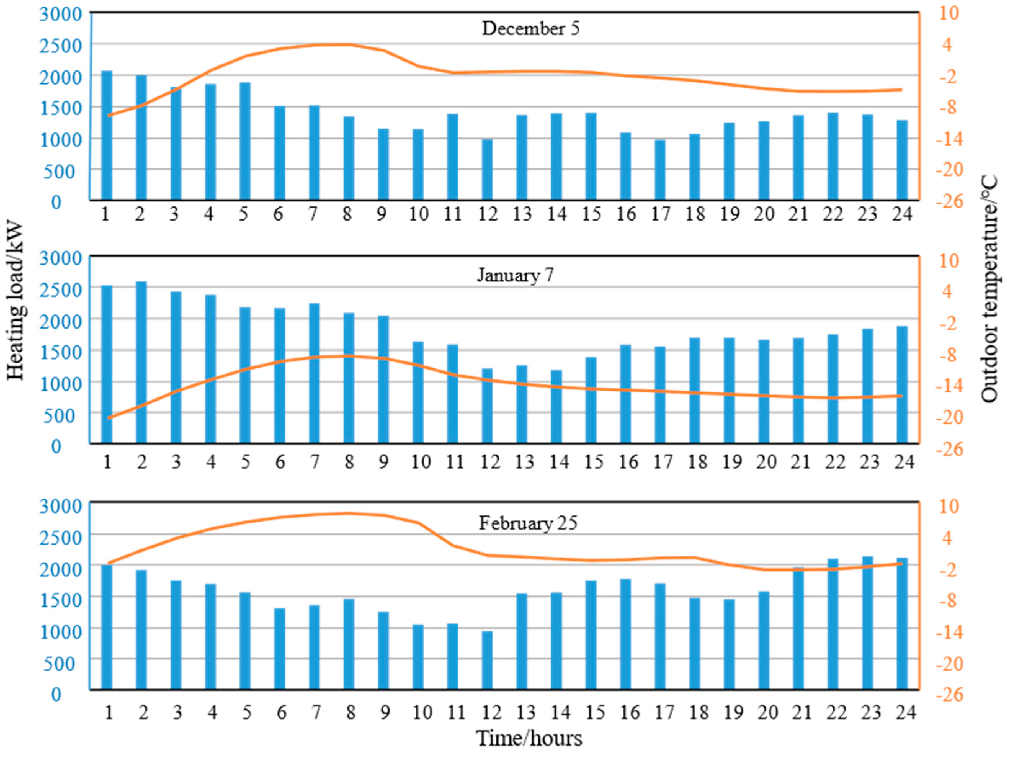
2.1. Additional Heat Demand

The design supply and return water temperatures for the SHN in this heat supply station are 55 °C and 45 °C, respectively, and centralized heating is provided to the residents annually from 15 November to 15 March. To facilitate the subsequent comparative analysis, the heating season was divided into three periods according to the outdoor temperature: the early cold period (from 1 November to 15 December); the mid cold period (from 15 December to 15 February of the following year), which represents the coldest time of the year; and the late cold period (from 15 February to 31 March). The hourly variations in heating loads and outdoor temperatures were collected for three typical days corresponding to the three periods, as shown in Figure 1.
In the figure, it can be noticed that despite being at different periods of the heating season, the changing trends of heating load throughout a day are relatively consistent, with the heating loads reaching their lowest points between 12:00 and 14:00 PM and peaking around 1:00 AM. The differences between the maximum and minimum values account for more than 45% of the maximum heating loads, which is appropriate for shifting peak heating loads with thermal storage devices.
Based on the building information presented in Table A1 of the Appendix A, the eQUEST 3.65 energy simulation software was used to predict the total heating load after the addition of the new buildings, with the results shown in Figure 2.
The results indicate that the daily heating load shows an increase and then a decrease during the heating season, with the maximum value of 6846 kW in mid-January. However, the current heating capacity of plate heat exchangers in the heat supply station is 3352 kW, which is significantly lower than the peak heating load, resulting in a heating shortfall of 3494 kW.

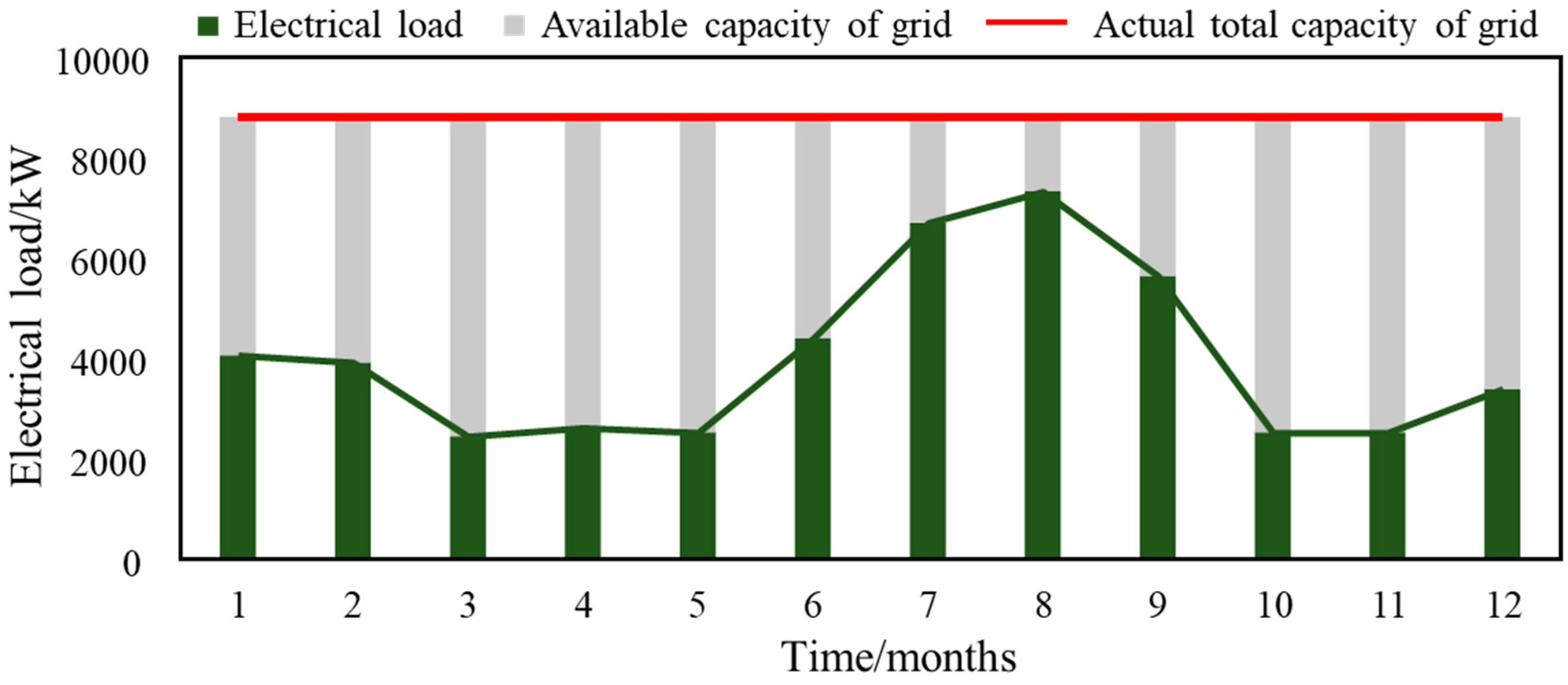
2.2. Available Capacity of the Grid

The monthly electrical loads for the research area from 2019 to 2020 are depicted in Figure 3. The data reveal two distinct peak periods of electricity consumption, occurring during the summer and winter. In summer, residents extensively utilize electric devices such as fans and air conditioners to mitigate the effects of rising outdoor temperatures, leading to a significant surge in electricity consumption. In winter, despite the presence of central heating in the research area, variations in thermal comfort and uneven heating supply prompt some residents to turn on additional electric heating equipment. Overall, the electricity consumption has remained relatively stable in recent years and exhibited a consistent seasonal variation, suggesting that the total electrical load in this area is predictable.
When developing supplemental heating measures for the area, it is crucial to avoid increasing the maximum capacity of the original grid. This means that the electricity consumption of the supplemental heating system must be constrained by the grid’s available capacity, which is defined as the difference between the grid’s actual total capacity and the residents’ electrical load. The actual total capacity of the grid was determined from the field research as 8800 kW. To account for the growth in electricity consumption due to new buildings, the residents’ electrical load was proportionally scaled based on the total building area. After expansion, the electrical load and the available capacity of the grid are illustrated in Figure 4.
It can be observed that, during the heating season, the available capacity of the grid is approximately 4800 kW. Therefore, when retrofitting the heat supply station for supplemental heating, the total electricity consumption of the newly added equipment must not exceed this limit, to ensure the safe operation of the grid.

3. Heat Pump Supplemental Heating Systems

The hot water from the PHN is discharged at 50 °C after passing through plate heat exchangers. By using this water as a low-temperature heat source and directing it into the evaporator of a heat pump, the waste heat can be further extracted and supplemented to the SHN via the condenser of the heat pump. This approach not only enhances the heating capacity of the heat supply station but also increases the temperature difference between the supply and return water in the PHN, thus reducing the water flow rate and the power consumption of water pumps. Considering the abundant waste heat resources of this heat supply station, this study proposes two supplemental heating systems based on different driving sources: an electric-driven VCSHS, and a hot-water-driven ASHS.

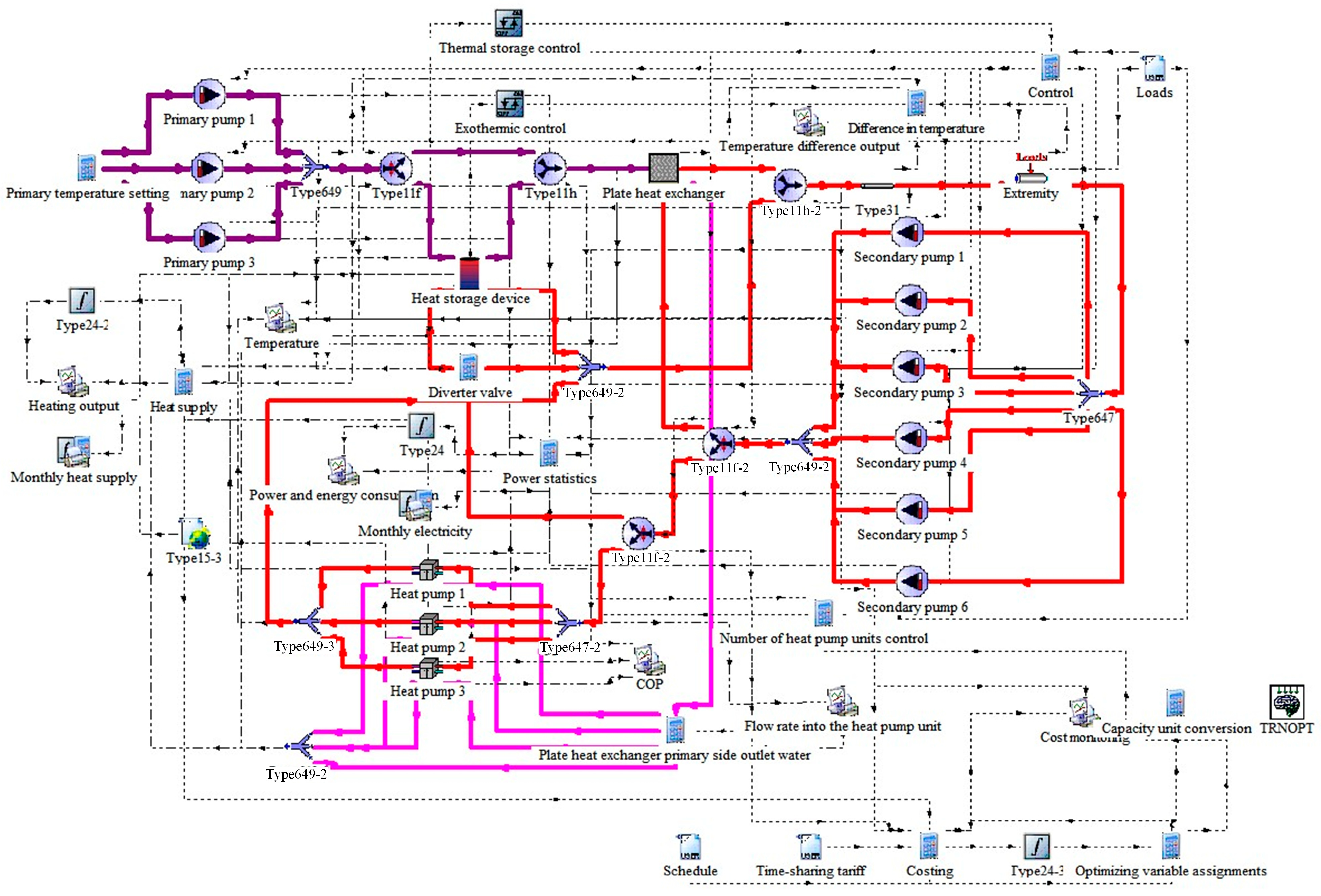
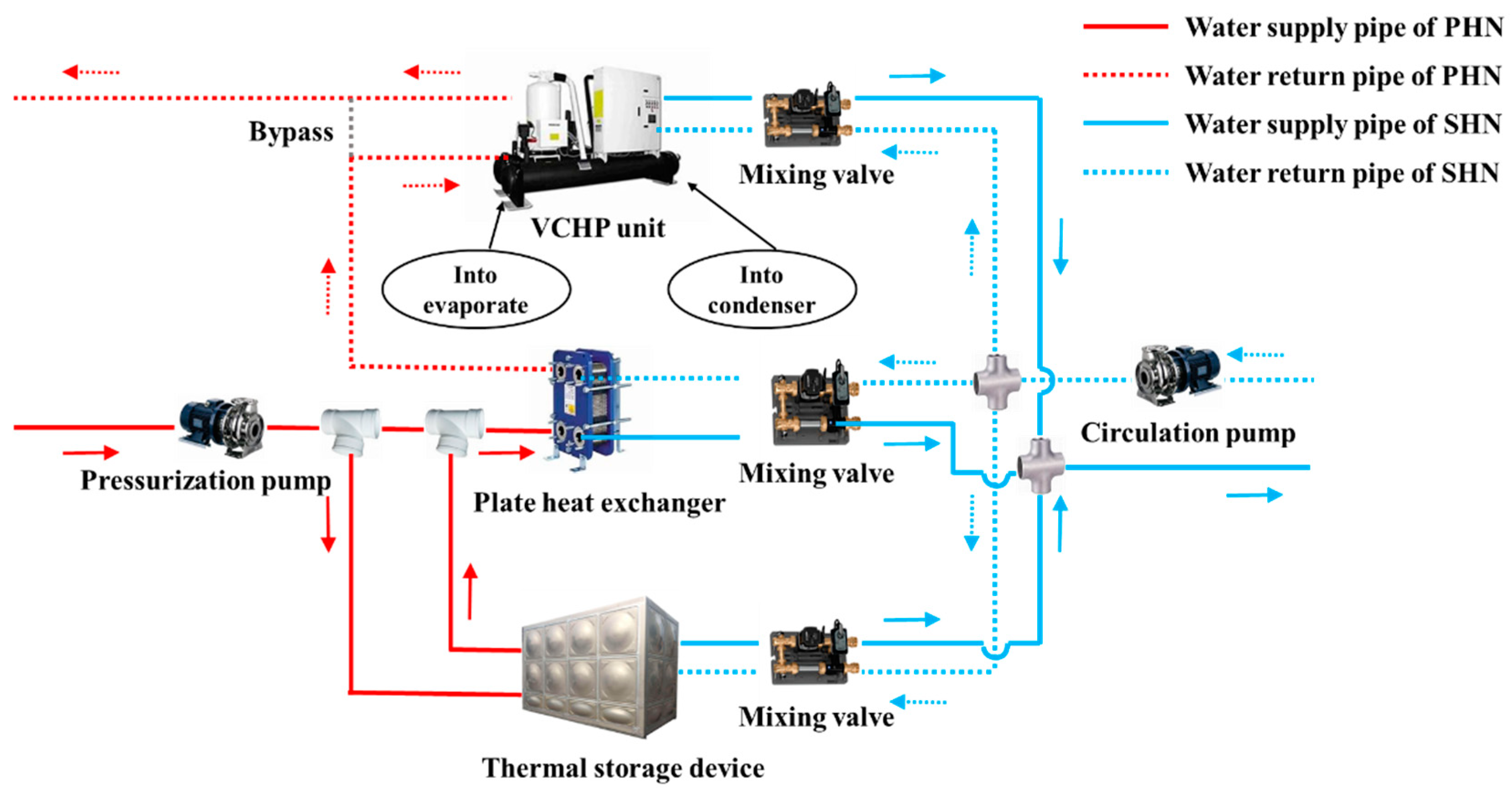
3.1. Electric-Driven VCSHS

Given the significant fluctuations in heating load throughout a day, a thermal storage device is installed in parallel to store excess heat from the PHN and then release the stored heat to the SHN when there is a shortage of heat. This strategy can transfer the peak heating load and allow rapid responses to continuously changing heat demands, thus preventing heat waste caused by untimely heating regulation.
To lower the size and cost of the thermal storage device, pressurization pumps are adopted to send the supply water of the PHN directly into the thermal storage device to increase the temperature difference between heat storage and release. The hot water from the thermal storage device, along with the supply water of the PHN, enters the plate heat exchanger to release heat. The water flow is then split into two branches: one goes to the evaporator of the vapor-compression heat pump for further heat extraction, while the other connects to the return pipe of the PHN. On the other hand, the return water of the SHN is sent by circulation pumps into the thermal storage device, the plate heat exchanger, or the condenser of the VCHP to absorb heat. Mixing valves connected to the supply and return pipes of the SHN are used to ensure a constant supply water temperature. In the heating cycle of the VCHP, heat is transferred from a low-temperature heat source to a high-temperature heat source by an electrically driven compressor. The operational principle of this system is shown in Figure 5.
The heat supplemented to the SHN by the electric-driven VCSHS is derived from two sources: partially from the municipal heat network, and partially converted from electricity. Therefore, it is essential to compare the costs of purchased heat and electricity when developing the operational strategy for this system to determine the optimal start-up sequence of each device.
(1)
When the cost of electric heating exceeds the cost of purchasing heat from the municipal heating network, the heating priorities are, in descending order, the plate heat exchanger, thermal storage device, and VCHP.
(2)
Conversely, when the cost of electric heating is lower than the cost of purchasing heat from the municipal heating network, the heating priorities are, in descending order, the VCHP, thermal storage device, and plate heat exchanger.

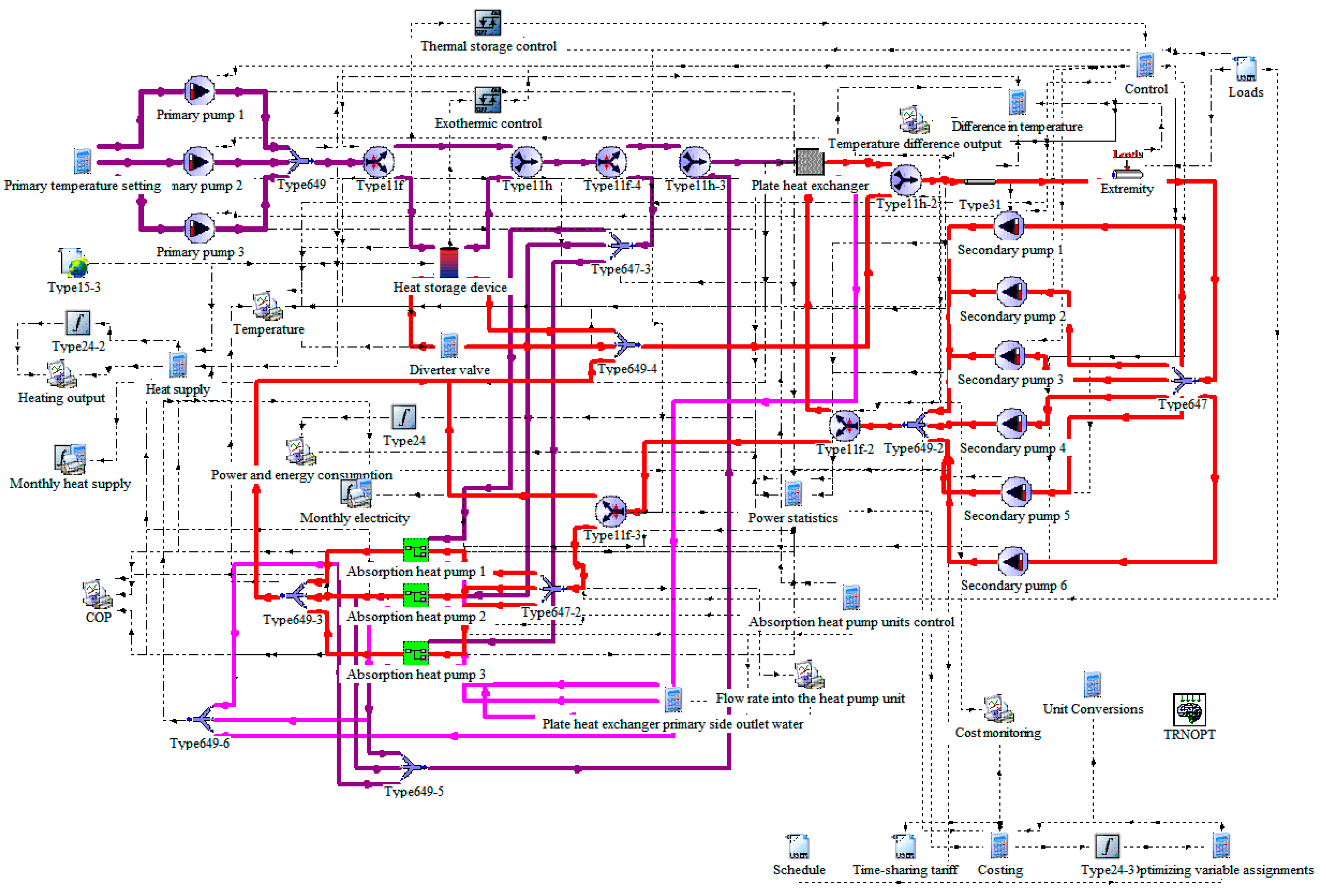
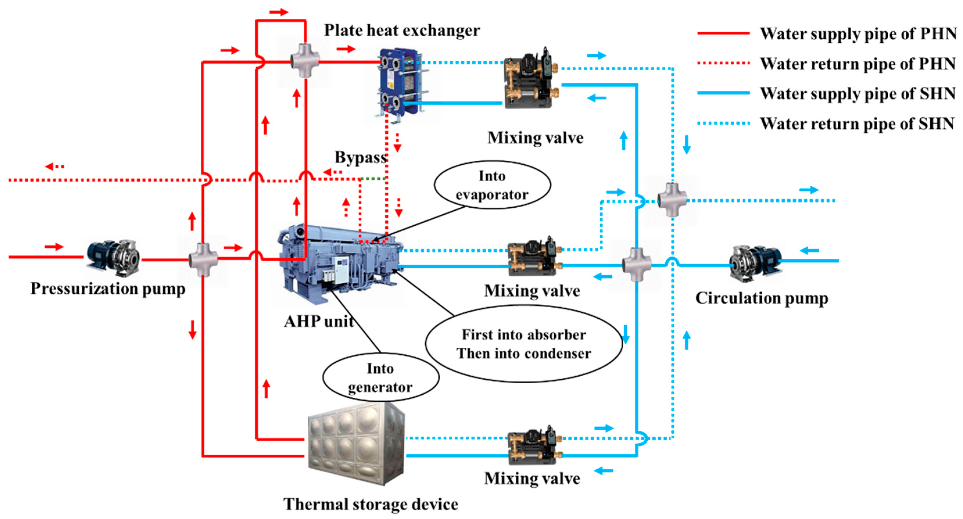
3.2. Hot-Water-Driven ASHS

The fundamental difference between AHPs and VCHPs lies in their driving sources: VCHPs are electrically driven to extract heat from a low-temperature heat source, whereas AHPs are driven by high-temperature heat. In the ASHS, the 110 °C supply water of the PHN is used as the driving source and pumped into the generator of the AHP to release heat. Similarly, the supply water of the PHN in this system is directly connected to the thermal storage device for high-temperature-difference thermal storage. The hot water from the generator and thermal storage device mixes with the supply water of the PHN and flows into the plate heat exchanger before being sent to the evaporator of the AHP for further heat release. The thermal storage device, plate heat exchanger, or AHP heats the return water of the SHN, which sequentially passes through the absorber and condenser as heat is absorbed from the AHP. The operational principle of the system is shown in Figure 6.
Unlike the electric-driven VCSHS, the supplementary heat of the ASHS comes solely from the municipal heating network. Consequently, there is no need to compare the prices of purchased heat and electricity when developing its operational strategy.
(1)
If the heating load does not exceed the heating capacity of the plate heat exchanger, there is no need to activate the heat pump or the thermal storage device for supplemental heating.
(2)
If the heating load exceeds the heating capacity of the plate heat exchanger but the thermal storage device still contains stored heat, priority is given to using it to meet the excess demand.
(3)
Only when the heating load exceeds the heating capacity of the plate heat exchanger, and when all of the stored heat in the thermal storage device has been depleted, will the AHP be activated to provide additional heating.

4. Methods

The mathematical models of integrating VCHPs and AHPs into the centralized heating system were built. Then, a bilevel optimization model focusing on energy savings and economic costs was developed.

4.1. Mathematical Models

According to the two supplemental heating schemes outlined earlier, the TRNSYS 18 platform was employed to construct the simulation models of the VCSHS and ASHS, as shown in Figure A2 and Figure A3 of the Appendix A, respectively. The mathematical models of each component in the two systems were established in accordance with the specific requirements of the corresponding modules in this platform.
(1)
Vapor-compression heat pump unit:
As the coefficient of performance (COP) and heating capacity of the VCHP are related to the inlet temperature of the evaporator, output temperature of the condenser, flow rate, etc., the dynamic performance of the VCHP was analyzed using a COP correction curve, which was provided by the manufacturer of the heat pump unit. The performance of the VCHP can be evaluated by the following equations:
Q VCHP = a 1 + b 1 × T VCHP , c , out + c 1 × T VCHP , c , out 2 + d 1 × G VCHP , c + e 1 × G VCHP , c 2 + f 1 × T VCHP , e , in + g 1 × T VCHP , e , in 2 + h 1 × G VCHP , e + i 1 × G VCHP , e 2 C O P VCHP = a 2 + b 2 × T VCHP , c , out + c 2 × T VCHP , c , out 2 + d 2 × G VCHP , c + e 2 × G VCHP , c 2 + f 2 × T VCHP , e , in + g 2 × T VCHP , e , in 2 + h 2 × G VCHP , e + i 2 × G VCHP , e 2
The power consumption of the VCHP can be calculated as follows:
W VCHP = Q VCHP / C O P VCHP
(2)
Absorption heat pump unit:
Similar to the VCHP model, the AHP model can be expressed as follows:
Q AHP = a 3 + b 3 × T AHP , c , out + c 3 × T AHP , c , out 2 + d 3 × T AHP , e , in + e 3 × T AHP , e , in 2 + f 3 × T AHP , g , in + g 3 × T AHP , g , in 2 C O P AHP = a 4 + b 4 × T AHP , c , out + c 4 × T AHP , c , out 2 + d 4 × T AHP , e , in + e 4 × T AHP , e , in 2 + f 4 × T AHP , g , in + g 4 × T AHP , g , in 2
The outputs of the AHP module can be expressed as follows:
T c , out = T c , in + Q AHP G AHP , c c p , AHP , c T g , out = T g , in Q AHP / C O P AHP G AHP , g c p , AHP , g T e , out = T e , in Q AHP Q AHP / C O P AHP G AHP , g c p , AHP , g
(3)
Plate heat exchanger:
Based on the principle of energy conservation, the steady-state heat transfer model of counterflow plate heat exchanger was established.
1 η p Q hw = Q cw = Q PHE Q hw = c p , hw G hw T hw , s T hw , r Q cw = c p , cw G cw T cw , s T cw , r Q PHE = K F L M T D
(4)
Thermal storage device:
The mathematical model of the thermal storage device was established as follows:
Q TS τ = Q TS τ 1 1 η t + α η hs W hs 1 α W hr η hr Δ τ α = 0 , 1
(5)
Mixing valve:
By regulating the mixing valve, the high-temperature supply water and low-temperature return water are mixed in a certain ratio to maintain the supply water towards residents within a reasonable range.
G z = G s + G m G z T z = G s T s + G m T m

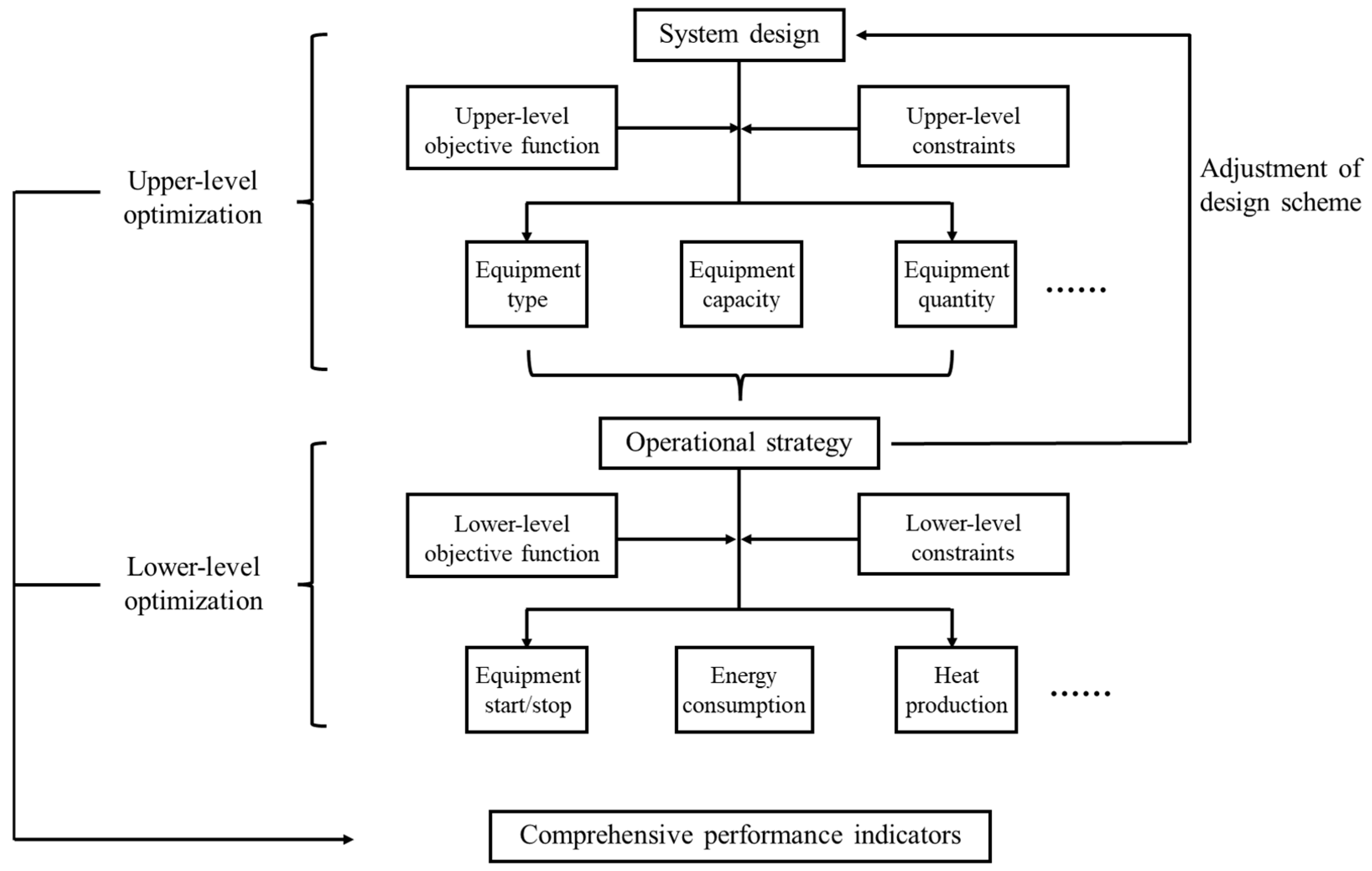
4.2. Bilevel Optimization

Due to the interdependent and mutually constraining nature of design and operation, it is challenging to achieve rational design and efficient operation of a heat pump supplemental heating system by optimizing these two aspects separately. In this study, by adopting the bilevel optimization approach, the optimization model was divided into two sub-optimization models consisting of a design optimization model (upper level) and an operational optimization model (lower level), and the two were optimized simultaneously, as shown in Figure 7.
The optimization process begins with the determination of the system design. Once the system design is established, the operational strategy of each device is adjusted to obtain the optimal objective function of the lower-level model. The results are then fed back to the upper-level model to update the system design. This iterative process continues until the overall result is optimized. The upper-level and lower-level models are interconnected through data transfer, ensuring that the output results of each level can be seamlessly passed to the other level as input conditions. The optimization models for both systems are primarily composed of four key components: the objective function, constraints, input conditions, and output results. The objective function aims to minimize the lifecycle cost of the entire system. The constraints encompass the available capacity of the grid, the balance between heat supply and demand, and the maximum capacity of each device. The input conditions include the residents’ hourly heating load, electricity prices, equipment costs, and basic equipment parameters. The output results provide the system design scheme, the operational strategy for each device, and key performance indicators such as operational cost and power consumption.

4.2.1. Design Optimization

(1)
Objective function:
Due to the outcomes of the upper level model necessitating evaluation in conjunction with the lower level model, the lifecycle cost, reflecting the initial cost and the operational cost of the system, is employed as the objective function for the upper model. The formula is as follows:
C LCC , min = C IC , min + C OC , min
C OC = Q PHN P h + W PG P el
(2)
Constraints:
In the supplemental heating systems, the total energy input should be balanced with the total energy output considering energy losses; thus, the energy balance constraint needs to be satisfied. In addition, for the electric-driven VCSHS, compliance with the “no grid capacity expansion” requirement necessitates incorporating the grid’s available capacity as one of the constraints.
Q dem τ Q sup τ 1 - η sup = Q HP τ + Q PHE τ + Q TS τ 1 - η sup Q sup = Q PHN η PHN + W HP η HP W PG = W ee τ E ac τ

4.2.2. Operational Optimization

(1)
Objective function:
When optimizing the operational strategy, the lower level model aims to minimize the total operational cost during the heating season by comparing the prices of purchased heat and electricity, and then determining the periods for heat supply and heat storage.
(2)
Constraints:
Operational optimization is subject to equipment capacity constraints in addition to the constraints of design optimization.
Q HP Q HP , max G P G P , max Φ TS , min Φ TS , min Φ TS , max

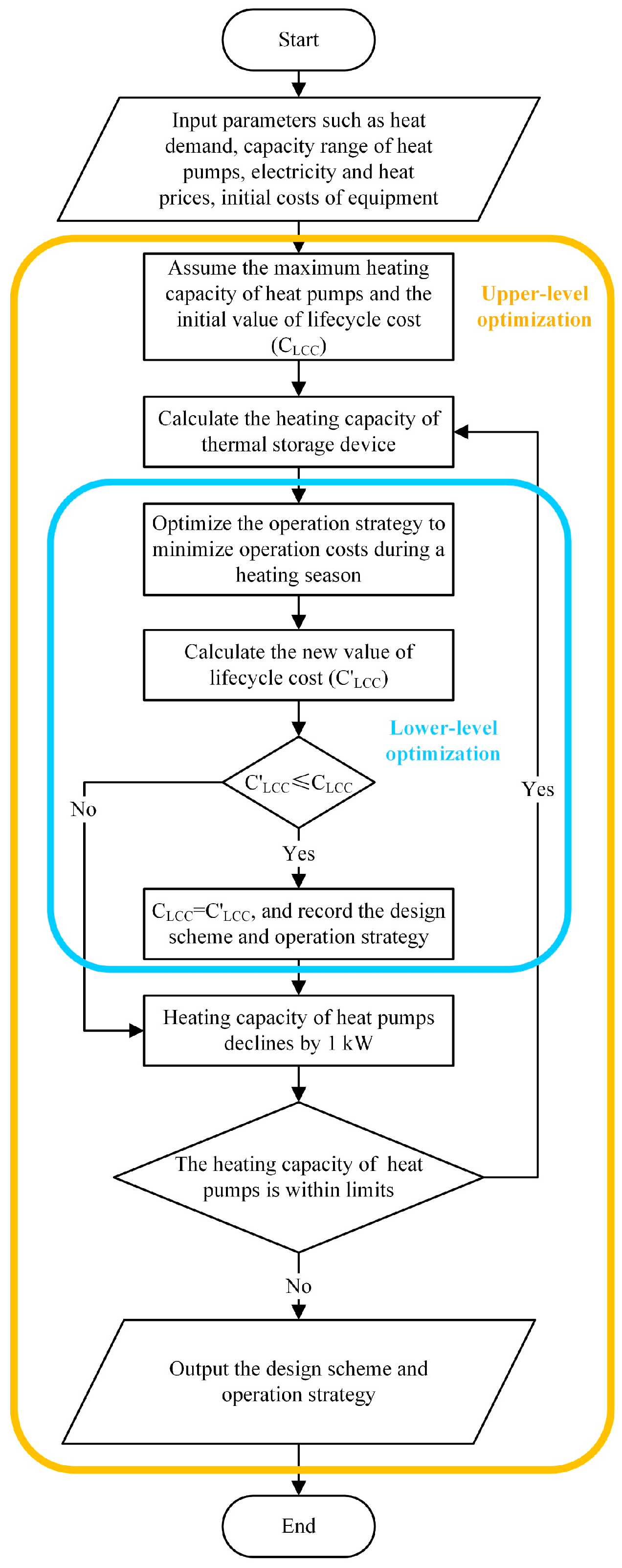
4.2.3. Solving Method

The original heat supply station was equipped with a single plate heat exchanger with a rated heating capacity of 3352 kW, three pressurization pumps with a flow rate of 16 m3/h, and three circulation pumps with a flow rate of 98 m3/h. With the increase in heat demand, the additional heating capacity provided by the ASHS is limited to 1680 kW if reducing the return water temperature of the PHN to 20 °C, which is insufficient to meet the heating shortfall. Consequently, it is necessary to expand the flow rate of the PHN for the ASHS. The system input parameters are shown in Table 1.
Investigating the market sales data and the billing standards released by the Beijing Municipal Development and Reform Commission, the initial cost, electricity price, and heat price involved in the optimization process are listed in Table 2.

4.3. Performance Evaluation Indicators

This study comprehensively evaluates the performance of the two supplemental heating systems from the perspectives of energy consumption, CO2 emissions, economy, and new equipment footprint.
(1)
Economic indicators:
The purchase and installation costs of the newly added equipment, as well as the energy costs for system operation, can be discounted at a certain rate to obtain the net present value (NPV) over the lifecycle. The calculation method is shown in Equation (12):
N P V = I C OC × 1 + r n 1 r 1 + r n C IC
where r is the discount rate, which is set to 5%; and n is the service life of the equipment, which is taken as 20 years.
(2)
Environmental indicators:
The annual CO2 emission of the system is used as the environmental indicator in this study, which can be calculated as follows:
E CO 2 = Q PHN F PHN + W PG F PG
where FPHN is the CO2 emission factor of the PHN, which is set to 284 gCO2/kWh; and FPG is the CO2 emission factor of the power grid, which is taken as 541 gCO2/kWh [40].

5. Results and Discussion

5.1. Results of System Optimization

The design optimization results for both systems are shown in Table 3. The results show that the additional heat pump capacity required to fill the same heating shortfall is 3150 kW for the VCSHS, which is 200 kW larger than that for the ASHS (2950 kW). However, the latter has a larger capacity of the thermal storage device. In addition, the results of the operational optimization of the two systems are shown in Figure 8 and Figure 9.
The statistics of the heat pumps’ cumulative operating hours in Figure 8a and Figure 9a show that the VCHP operates for a total of 381 h, accounting for 13.12% of the heating season, while the AHP operates for 318 h, representing 10.95%. This difference arises because the thermal storage device in the ASHS has a 200 kW higher capacity than that in the VCSHS. Based on the prioritization of each heating device in the ASHS, the heat demand can be satisfied for a longer time by the thermal storage device and the plate heat exchanger. Meanwhile, in Figure 8b and Figure 9b, it can be observed that for the VCSHS, the thermal storage device requires approximately 16 to 30 h to complete a full cycle of heat storage and release actions, lasting from the end of the early cold period (the 792nd hour) to the middle of the late cold period (the 2288th hour). In contrast, the ASHS has a more frequent heat storage and release cycle, with the shortest cycle being only 11 h, and the thermal storage device begins supplying heat as early as the beginning of the early cold period.
Figure 10 and Figure 11 illustrate the scheduling of each heating device on a typical day for both systems. Obviously, the plate heat exchanger, serving as the primary heating device, bears most of the heating load, while the heat pump and thermal storage device play the role of heat supplementation and peak load shifting. The reason for this is that the cost of electric heating during peak hours and plain hours in Beijing is higher than that of purchasing heat from the municipal heat network; therefore, in most cases, the plate heat exchanger is prioritized to be activated for heat supply. For the VCSHS, employing the electric-driven VCHP for heat supplementation during the early morning hours is most cost-effective due to the higher heat demand, coinciding with the lower electricity price. In addition, as the outdoor temperature gradually rises during the day, the building’s heating load decreases, resulting in a surplus of heat in the PHN. Consequently, a portion of the heat is stored in the thermal storage device and then prioritized for heat supplementation once the heating load exceeds the heating capacity of the PHN. The difference with the VCSHS, however, is that in the ASHS the thermal storage device also activates the heat storage during the early morning hours. Since the system extracts heat solely from the municipal heat network, the total heating capacity of the AHP combined with the plate heat exchanger may surpass the current heat demand when turning on the AHP.

5.2. Performance Analysis

To comprehensively evaluate the performance of these two heat pump supplemental heating systems in augmenting the heating capacity of the heat supply station, a comparative analysis was conducted, focusing on their operational energy consumption, economic performance, and the footprint of the additional equipment.

5.2.1. Analysis of Energy Consumption

The annual energy consumption of both systems during the heating season is presented in Table 4. The results show that the heat consumption of the two systems is nearly identical, with the plate heat exchanger accounting for the majority (91.20% for the VCSHS and 91.37% for the ASHS). The electricity consumption of the ASHS is significantly lower than that of the VCSHS because the AHP is driven by heat, and electricity is consumed solely by the water pumps in this system, whereas the heat pump consumes 54.82% of electricity in the VCSHS. Overall, since the annual energy consumption of the VCSHS is 0.85% higher than that of the ASHS, the adoption of the AHP for heat supplementation is slightly more energy-efficient. Moreover, the ASHS has the best CO2 mitigation potential, and it reduces the CO2 emissions by about 2% compared with the VCSHS, which can be attributed to the lower carbon emission factor of fossil fuels compared to that of electricity, along with the higher proportion of heat in its energy consumption.

5.2.2. Economic Analysis

For a supplemental heating system, the higher the NPV, the better the economic performance and the higher the return on investment. The economic indicators of the two systems are summarized in Table 5. To address the same heating shortfall, the initial cost for the ASHS is nearly 1 million CNY more expensive than that for the VCSHS. Despite this significant difference in upfront costs, both systems exhibit comparable annual energy consumption, resulting in nearly equivalent annual operational costs. According to these financial considerations, the VCSHS boasts a higher NPV, thereby signaling superior economic performance.

5.2.3. Analysis of New Equipment Footprint

The available space in the original heat supply station is both fixed and limited. When implementing a heat pump supplemental heating scheme, due to the introduction of multiple new devices, calculating the footprint of the added equipment at the design stage can facilitate a more comprehensive assessment of the practical application of the supplemental heating system. Based on the quantity and capacity of the additional equipment associated with the two supplemental heating systems detailed in Table 3, the area occupied by each device was calculated with reference to the dimensions of mature products available in the market—specifically of heat pump units, water pumps, and thermal storage tanks—and the results are shown in Table 6.
The data reveal that although the VCSHS requires a greater heat pump capacity, its simpler working principle leads to a more compact structure of the heat pump unit. Additionally, the thermal storage capacity in this system is smaller, resulting in a total occupied area of 99.552 m2 for the new equipment, nearly 30% less than that of the ASHS, thus achieving significant space savings.

5.3. Analysis of Regional Applicability

For a given heating area, the climate zone directly influences the building’s heating load, which leads to variations in the heating shortfall of the heat supply station, thereby altering the design capacity of each new device. In addition, differences in energy tariffs across various climate zones also impact the operational strategy of supplemental heating systems. Therefore, to explore the regional applicability of the two supplemental heating systems, Shenyang, a representative city in a severe cold region, was selected for comparative analysis alongside Beijing. Table 7 provides the basic parameters for these two representative cities.
Based on the bilevel optimization method, the system optimization results, energy consumption, and economic indicators for different climate zones were obtained, as shown in Table 8 and Table 9.
The data in Table 8 demonstrate that, for the same heating area, the equipment capacity required for both systems in the severe cold region is greater than that in the cold region. This reason for this is that the lower outdoor temperatures in the severe cold region during winter result in a higher heating demand and a correspondingly larger heating shortfall for the heat supply station. Table 9 highlights that both systems exhibit similar characteristics in terms of operational energy consumption across different climate zones. Specifically, the VCSHS exhibits higher electricity consumption, whereas the ASHS demonstrates greater thermal energy consumption. Overall, the operational energy consumption of the VCSHS marginally surpasses that of the ASHS. On the other hand, despite the VCSHS’s lower initial costs, the heat price subsidy implemented in Shenyang markedly inflates the cost of electric heating, rendering it substantially higher than the cost of purchasing heat. As a result, the annual operational costs of the ASHS are significantly lower than those of the VCSHS, which makes the ASHS more advantageous for widespread adoption in the severe cold region.

6. Conclusions

This study proposes two supplemental heating solutions: a VCSHS and an ASHS. Using the TRNSYS platform, simulation models for both systems were developed to conduct a bilevel optimization of the system design and operational strategy. Finally, a comprehensive comparison of the two supplemental heating solutions was undertaken, focusing on operational energy consumption, economic efficiency, the footprint of new equipment, and regional applicability. The main conclusions are as follows:
(1)
Confronted with the dual challenges of inadequate heating capacity of the heat supply station and elevated return water temperature of the PHN, heat pump technology can be employed to further extract heat from the PHN and transfer it to the SHN.
(2)
The VCSHS exhibits higher electricity consumption, whereas the ASHS demonstrates greater thermal energy consumption. Overall, the operational energy consumption of the VCSHS is 0.85% higher than that of the ASHS, leading to a 2% increase in carbon emissions.
(3)
In the cold region, the NPV of the VCSHS is about 1 million CNY higher than that of the ASHS, resulting in better economics, while in the severe cold region with the lower heat price, the ASHS is more favorable for promotion.
(4)
The footprint required for the new equipment in the VCSHS is 99.552 m2, nearly 30% smaller than that in the ASHS, resulting in significant space savings.
In practical engineering applications, when supplementing an equivalent amount of heat, the VCSHS typically exhibits higher total operational energy consumption and greater CO2 emissions compared to the ASHS. However, its economic benefits are affected by fluctuations in energy costs. In regions with relatively low heat prices, the ASHS tends to hold a distinct advantage. Additionally, when the available space within heat supply stations is limited, the VCSHS, which occupies a smaller footprint, should be prioritized.

Author Contributions

Methodology, H.Z. and W.Z.; Software, Q.W.; Investigation, Y.H. and S.L.; Writing—original draft, Z.W. (Zhihao Wan); Writing—review & editing, Z.W. (Zhaoying Wang) and X.F.; Funding acquisition, W.Z. All authors have read and agreed to the published version of the manuscript.

Funding

This research was funded by the National Natural Science Foundation of China grant number 52478101. And the APC was funded by Zhihao Wan.

Institutional Review Board Statement

Not applicable.

Informed Consent Statement

Not applicable.

Data Availability Statement

Data are contained within the article.

Conflicts of Interest

The authors declare no conflict of interest.

Nomenclature

Abbreviations Subscripts
AHPAbsorption heat pumpacAvailable capacity of grid
ASHSAbsorption heat pump supplemental heating systemcCondenser
CNYChinese YuandemHeat demand
COPCoefficient of performancehHeat
LMTDLogarithmic mean temperature differencehsHeat storage
NPVNet present valuehrHeat release
PHNPrimary heat networkcwCold water
SHNSecondary heat networkeEvaporator
VCHPVapor-compression heat pumpeeElectric equipment
VCSHSVapor-compression heat pump supplemental heating systemelElectricity
Symbols gGenerator
a, b, c, d, e, f, g, h, iCorrection factorsHPHeat pump
CCost, CNYhwHot water
cpSpecific heat capacity, kJ/kg·KICInitial cost
EElectricity consumption, WinInlet
FHeat transfer area, m2LCCLifecycle cost
FPHNCO2 emission factor of the PHN, gCO2/kWhmMixed water
FPGCO2 emission factor of the PG, gCO2/kWhmaxMaximum value
GFlow rate, m3/hminMinimum value
KHeat transfer coefficient, W/m2·KOCOperational cost
nService life of equipment, yearsoutOutlet
PPrice, CNYpHeat loss of plate heat exchanger
QHeat capacity, WPGPower grid
rDiscount rate, %PHEPlate heat exchanger
TTemperature, °CrReturn water
WPower, WsSupply water
αStatus variable, using to illustrate whether the TS is charging or dischargingsupHeat supply
ηEfficiency, %tHeat loss of thermal storage device
τTime, sTSThermal storage device
ΦHeat storage, WzTotal water

Appendix A

In this study, eQUEST software was used to simulate the building’s heat loads. Through field research and testing, the information about building envelopes was obtained, as detailed in Table A1. The overall window-to-wall ratio stands at approximately 0.25, while the building form factor is around 0.22.
Table A1. Parameters of building envelopes.
Envelope TypeMaterialsThickness (mm)Thermal Conductivity (W/m·K)Specific Heat Capacity (kJ/kg·K)
External wallsFireproof heat-retaining board600.0451.22
Cement mortar800.811.05
Reinforced concrete1201.740.92
Cement mortar200.811.05
Cement mortar200.931.05
Concrete of grade C20401.510.92
RoofExtruded polystyrene board1150.031.22
Concrete700.891.05
Reinforced concrete1201.740.92
The solution steps of the bilevel optimization method are illustrated in Figure A1. Firstly, basic information such as heat demand, the heating capacity range of heat pumps, local electricity and heat prices, and the initial costs of each device is input. Subsequently, based on the heat demand, the heating capacity of heat pumps is hypothesized to determine the heating capacity of the thermal storage device, thereby calculating the initial value of the system’s lifecycle cost under the most unfavorable conditions. Aiming to minimize the operational cost during the heating season, an optimal operational strategy for the system is formulated, resulting in a new value for the system’s lifecycle cost. Then, this new value is compared with the initial value; if it exceeds the initial value, the heating capacity of the heat pumps is adjusted, and then the operational strategy is re-optimized until the system’s lifecycle cost is minimized. Finally, the heating capacity of the heat pumps is verified against the constraint conditions; if unsatisfied, the optimal design and operation scheme of the system is output.
Figure A1. Solution steps of the bilevel optimization method.
Sustainability 17 02513 g0a1
Figure A2. TRNSYS model of VCSHS.
Sustainability 17 02513 g0a2
Figure A3. TRNSYS model of ASHS.
Sustainability 17 02513 g0a3

References

  1. Li, Y.; Ding, Z.; Shakerin, M.; Zhang, N. A multi-objective optimal design method for thermal energy storage systems with PCM: A case study for outdoor swimming pool heating application. J. Energy Storage 2020, 29, 101371. [Google Scholar] [CrossRef]
  2. Fletcher, C.; Ripple, W.J.; Newsome, T.; Barnard, P.; Beamer, K.; Behl, A.; Bowen, J.; Cooney, M.; Crist, E.; Field, C.; et al. Earth at risk: An urgent call to end the age of destruction and forge a just and sustainable future. PNAS Nexus 2024, 3, 106. [Google Scholar] [CrossRef]
  3. Du, Y.; Blocken, B.; Pirker, S. A novel approach to simulate pollutant dispersion in the built environment: Transport-based recurrence CFD. Build. Environ. 2020, 170, 106604. [Google Scholar] [CrossRef]
  4. Hua, E.; Engel, B.A.; Guan, J.; Yin, J.; Wu, N.; Han, X.; Sun, S.; He, J.; Wang, Y. Synergy and competition of water in Food-Energy-Water Nexus: Insights for sustainability. Energy Convers. Manag. 2022, 266, 115848. [Google Scholar] [CrossRef]
  5. Toroxel, J.L.; Silva, S.M. A review of passive solar heating and cooling technologies based on bioclimatic and vernacular architecture. Energies 2024, 17, 1006. [Google Scholar] [CrossRef]
  6. Agathokleous, R.; Barone, G.; Buonomano, A.; Forzano, C.; Kalogirou, S.A.; Palombo, A. Building facade integrated solar thermal collectors for air heating: Experimentation, modelling and applications. Appl. Energy 2019, 239, 658–679. [Google Scholar] [CrossRef]
  7. Tumminia, G.; Guarino, F.; Longo, S.; Aloisio, D.; Cellura, S.; Sergi, F.; Brunaccini, G.; Antonucci, V.; Ferraro, M. Grid interaction and environmental impact of a net zero energy building. Energy Convers. Manag. 2020, 203, 112228. [Google Scholar] [CrossRef]
  8. Eslami, S.; Noorollahi, Y.; Marzband, M.; Anvari-Moghaddam, A. District heating planning with focus on solar energy and heat pump using GIS and the supervised learning method: Case study of Gaziantep, Turkey. Energy Convers. Manag. 2022, 269, 116131. [Google Scholar] [CrossRef]
  9. Li, Y.; Nord, N.; Xiao, Q.; Tereshchenko, T. Building heating applications with phase change material: A comprehensive review. J. Energy Storage 2020, 31, 101634. [Google Scholar] [CrossRef]
  10. Zhang, H.; Wang, Y.; Liu, X.; Wan, F.; Zheng, W. Multi-Objective Optimization with Active–Passive Technology Synergy for Rural Residences in Northern China. Energies 2024, 17, 1539. [Google Scholar] [CrossRef]
  11. Elżbieta, K.; Katarzyna, Ł.; Piotr, P. Use of Renewable Energy Sources in the European Union and the Visegrad Group Countries-Results of Cluster Analysis. Energies 2021, 14, 5680. [Google Scholar] [CrossRef]
  12. Connolly, D. Heat roadmap europe: Quantitative comparison between the electricity, heating, and cooling sectors for different European countries. Energy 2017, 139, 580–593. [Google Scholar] [CrossRef]
  13. Hua, P.; Wang, H.; Xie, Z.; Lahdelma, R. District heating load patterns and short-term forecasting for buildings and city level. Energy 2024, 289, 129866. [Google Scholar] [CrossRef]
  14. Yuan, M.; Mathiesen, V.B.; Schneider, N.; Xia, J.; Zheng, W.; Sorknæs, P.; Lund, H.; Zhang, L. Renewable energy and waste heat recovery in district heating systems in China: A systematic review. Energy 2024, 294, 130788. [Google Scholar] [CrossRef]
  15. Pellegrini, M.; Bianchini, A. The innovative concept of cold district heating networks: A literature review. Energies 2018, 11, 236. [Google Scholar] [CrossRef]
  16. Averfalk, H.; Ingvarsson, P.; Persson, U.; Gong, M.; Werner, S. Large heat pumps in Swedish district heating systems. Renew. Sustain. Energy Rev. 2017, 79, 1275–1284. [Google Scholar] [CrossRef]
  17. Ji, Y.; Chen, X.; Yang, X.; Wang, X.; Wang, X.; Xie, J.; Ju, G. Research on the framework and meteorological parameter optimization method of dynamic heating load prediction model for heat-exchange stations. Energy 2024, 309, 133125. [Google Scholar] [CrossRef]
  18. Jobard, X.; Padey, P.; Guillaume, M.; Duret, A.; Pahud, D. Development and testing of novel applications for adsorption heat pumps and chillers. Energies 2020, 13, 615. [Google Scholar] [CrossRef]
  19. Volkova, A.; Krupenski, I.; Ledvanov, A.; Hlebnikov, A.; Lepiksaar, K.; Latõšov, E.; Mašatin, V. Energy cascade connection of a low-temperature district heating network to the return line of a high-temperature district heating network. Energy 2020, 198, 117304. [Google Scholar] [CrossRef]
  20. Sun, F.; Xie, Y.; Svendsen, S.; Fu, L. New low-temperature central heating system integrated with industrial exhausted heat using distributed electric compression heat pumps for higher energy efficiency. Energies 2020, 13, 6582. [Google Scholar] [CrossRef]
  21. Anand, A.; Deb, C. The potential of remote sensing and GIS in urban building energy modelling. Energy Built Environ. 2024, 5, 957–969. [Google Scholar] [CrossRef]
  22. United Nations, Department of Economic and Social Affairs, Population Division. World Urbanization Prospects: The 2018 Revision; United Nations: New York, NY, USA, 2019. [Google Scholar]
  23. Song, Z.; Wang, N.; You, S.; Wang, Y.; Zhang, H.; Wei, S.; Zheng, X.; Guo, J. Integration of geothermal water into secondary network by absorption-heat-pump-assisted district heating substations. Energy Build. 2019, 202, 109403. [Google Scholar] [CrossRef]
  24. Gao, P.; Chang, M.-M.; Zhang, C.-L.; Shao, L.L. System principles and applications of hybrid sorption–compression heat pump—A review. Int. J. Refrig. 2019, 108, 14–25. [Google Scholar] [CrossRef]
  25. Gado, M.G.; Hassan, H. Energy-saving potential of compression heat pump using thermal energy storage of phase change materials for cooling and heating applications. Energy 2023, 263, 126046. [Google Scholar] [CrossRef]
  26. Gadd, H.; Werner, S. Thermal energy storage systems for district heating and cooling. In Advances in Thermal Energy Storage Systems; Woodhead Publishing: Cambridge, UK, 2021; pp. 625–638. [Google Scholar]
  27. Olympios, A.V.; Sapin, P.; Freeman, J.; Olkis, C.; Markides, C.N. Operational optimisation of an air-source heat pump system with thermal energy storage for domestic applications. Energy Convers. Manag. 2022, 273, 116426. [Google Scholar] [CrossRef]
  28. Love, J.; Smith, A.Z.; Watson, S.; Oikonomou, E.; Summerfield, A.; Gleeson, C.; Biddulph, P.; Chiu, L.F.; Wingfield, J.; Martin, C.; et al. The addition of heat pump electricity load profiles to GB electricity demand: Evidence from a heat pump field trial. Appl. Energy 2017, 204, 332–342. [Google Scholar] [CrossRef]
  29. Đuranović, M.; Živić, M.; Stojkov, M.; Lujić, R. Analysis of energy consumption of a thermo-technical system with an absorption heat pump. Teh. Vjesn. 2024, 31, 967–972. [Google Scholar]
  30. Tarique, S.M.; Siddiqui, M.A. Performance and economic study of the combined absorption/compression heat pump. Energy Convers. Manag. 1999, 40, 575–591. [Google Scholar] [CrossRef]
  31. Dzierwa, P.; Peret, P.; Trojan, M.; Kaczmarski, K. Energy and economic analysis of flue gas heat recovery systems improving the energy efficiency of gas cogeneration units. E3S Web Conf. 2024, 551, 01006. [Google Scholar] [CrossRef]
  32. Mirl, N.; Schmid, F.; Bierling, B.; Spindler, K. Design and analysis of an ammonia-water absorption heat pump. Appl. Therm. Eng. 2020, 165, 114531. [Google Scholar] [CrossRef]
  33. Wang, L.; Zhang, S.; Fu, Y.; Liu, M.; Liu, J.; Yan, J. Heat–power decoupling for the CHP unit by utilizing heat storage in the district heating system integrated with heat pumps: Dynamic modeling and performance analysis. Energy 2024, 306, 132485. [Google Scholar] [CrossRef]
  34. Wang, X.; Tian, H.; Yan, F.; Feng, W.; Wang, R.; Pan, J. Optimization of a distributed energy system with multiple waste heat sources and heat storage of different temperatures based on the energy quality. Appl. Therm. Eng. 2020, 181, 115975. [Google Scholar] [CrossRef]
  35. Jouhara, H.; Khordehgah, N.; Almahmoud, S.; Delpech, B.; Chauhan, A.; Tassou, S.A. Waste heat recovery technologies and applications. Therm. Sci. Eng. Prog. 2018, 6, 268–289. [Google Scholar] [CrossRef]
  36. Jiang, X.; Jing, Z.; Li, Y.; Wu, Q.; Tang, W. Modelling and operation optimization of an integrated energy based direct district water-heating system. Energy 2014, 64, 375–388. [Google Scholar] [CrossRef]
  37. Buoro, D.; Pinamonti, P.; Reini, M. Optimization of a distributed cogeneration system with solar district heating. Appl. Energy 2014, 124, 298–308. [Google Scholar] [CrossRef]
  38. Allouhi, A.; Agrouaz, Y.; Amine, M.B.; Rehman, S.; Buker, M.; Kousksou, T.; Jamil, A.; Benbassou, A. Design optimization of a multi-temperature solar thermal heating system for an industrial process. Appl. Energy 2017, 206, 382–392. [Google Scholar] [CrossRef]
  39. Carpaneto, E.; Lazzeroni, P.; Repetto, M. Optimal integration of solar energy in a district heating network. Renew. Energy 2015, 75, 714–721. [Google Scholar] [CrossRef]
  40. Building Energy Efficiency Research Centre of Tsinghua University. China Building Energy Efficiency Annual Development Research Report 2023; China Architecture & Building Press: Beijing, China, 2023. [Google Scholar]
Figure 1. Hourly heating loads and outdoor temperatures.
Sustainability 17 02513 g001
Figure 2. Daily heating load during the heating season.
Sustainability 17 02513 g002
Figure 3. Electrical load curves of the research area in 2019 and 2020.
Sustainability 17 02513 g003
Figure 4. Electrical load and available capacity of the grid after expansion.
Sustainability 17 02513 g004
Figure 5. Schematic diagram of VCSHS.
Sustainability 17 02513 g005
Figure 6. Schematic diagram of ASHS.
Sustainability 17 02513 g006
Figure 7. Structure of the bilevel optimization model.
Sustainability 17 02513 g007
Figure 8. Operational optimization result of VCSHS.
Sustainability 17 02513 g008aSustainability 17 02513 g008b
Figure 9. Operational optimization results of ASHS.
Sustainability 17 02513 g009aSustainability 17 02513 g009b
Figure 10. System scheduling of VCSHS on a typical day.
Sustainability 17 02513 g010
Figure 11. System scheduling of ASHS on a typical day.
Sustainability 17 02513 g011
Table 1. Input parameters of optimization models.
ItemParameterValue
Plate heat exchanger (original)Design heating capacity3352 kW
Rated outlet temperature50 °C
Pressurization pump (original)Number of units3 units
Rated flow rate16 m3/h
Circulation pump (original)Number of units3 units
Rated flow rate98 m3/h
Heat pumpNumber of units3 units
Power range20–100%
Pressurization pump (only for ASHS)Number of units1 unit
Circulation pumpNumber of units3 units
Thermal storage deviceMaximum storage temperature90 °C
Minimum discharge temperature55 °C
PHNSupply water temperature110 °C
SHNPeak heating load6846 kW
Supply water temperature55 °C
Return water temperature45 °C
Table 2. Reference to cost values.
ItemClassificationValue
Initial costVCHP450 CNY/kW
AHP750 CNY/kW
Water pump140 CNY/(m3/h)
Thermal storage device5000 CNY/GJ
Installation cost 2.5% of purchasing cost
Electricity pricePeak hours (10:00–13:00, 17:00–22:00)1.29 CNY/kWh
Plain hours (7:00–10:00, 13:00–17:00, 22:00–23:00)0.77 CNY/kWh
Valley hours (23:00–7:00 the next day)0.29 CNY/kWh
Heat price-86.5 CNY/GJ
Break-even pointBreak-even point is the cost of electric heating that is equal to the heat price0.3114 CNY/kWh
Table 3. Design optimization results of two supplemental heating systems.
ItemVCSHSASHS
Rated capacity of heat pump 11100 kW1050 kW
Rated capacity of heat pump 2850 kW750 kW
Rated capacity of heat pump 31200 kW1150 kW
Rated flow rate of circulation pump 194 m3/h97 m3/h
Rated flow rate of circulation pump 298 m3/h91 m3/h
Rated flow rate of circulation pump 3102 m3/h106 m3/h
Rated flow rate of pressurization pump 1-16 m3/h
Thermal storage device capacity32.52 GJ46.61 GJ
Table 4. Energy consumption of two supplemental heating systems.
CategoryItemVCSHSASHS
Electricity (kWh)Pressurization pump1.16 × 1049.79 × 103
Circulation pump6.51 × 1046.51 × 104
Heat pump9.32 × 104-
Total1.70 × 1057.49 × 104
Heat (kWh)Plate heat exchanger6.84 × 1066.88 × 106
Heat pump3.67 × 1053.32 × 105
Thermal storage device2.85 × 1053.20 × 105
Total7.50 × 1067.53 × 106
CO2 emissions (tons)Total2221.972179.04
Table 5. Economy of two supplemental heating systems.
System TypeInitial Cost (Million CNY)Annual Operational Cost (Million CNY)NPV (Million CNY)
VCSHS1.70872.483019.0305
ASHS2.87492.466218.0744
Table 6. Footprint of new equipment for two supplemental heating systems.
Equipment TypeVCSHSASHS
Heat pump 1Length × width: 3540 × 2100 mm
Occupied area: 7.434 m2
Length × width: 5000 × 2250 mm
Occupied area: 11.25 m2
Heat pump 2Length × width: 3500 × 1800 mm
Occupied area: 6.3 m2
Length × width: 3950 × 2180 mm
Occupied area: 8.611 m2
Heat pump 3Length × width: 3540 × 2100 mm
Occupied area: 7.434 m2
Length × width: 5000 × 2250 mm
Occupied area: 11.25 m2
Circulation pump 1Length × width: 1800 × 860 mm
Occupied area: 1.548 m2
Length × width: 1800 × 860 mm
Occupied area: 1.548 m2
Circulation pump 2Length × width: 1800 × 860 mm
Occupied area: 1.548 m2
Length × width: 1800 × 860 mm
Occupied area: 1.548 m2
Circulation pump 3Length × width: 1800 × 860 mm
Occupied area: 1.548 m2
Length × width: 1800 × 860 mm
Occupied area: 1.548 m2
Pressurization pump 1-Length × width: 1300 × 540 mm
Occupied area: 0.702 m2
Thermal storage deviceHeight: 3000 mm
Occupied area: 73.74 m2
Height: 3000 mm
Occupied area: 105.69 m2
Total99.552 m2142.147 m2
Table 7. Basic parameters for cities represented by different climate zones.
ShenyangBeijing
Climate zoneSevere cold regionCold region
Heating season1 November–31 March15 November–15 March
Peak heating load7470 kW6846 kW
Heating shortfall4118 kW3494 kW
Electricity price0.781 CNY/kWhPeak hours: 1.29 CNY/kWh
Plain hours: 0.77 CNY/kWh
Valley hours: 0.29 CNY/kWh
Heat price44 CNY/GJ86.5 CNY/GJ
Break-even points0.1584 CNY/kWh0.3114 CNY/kWh
Table 8. Optimal equipment capacity for cities represented by different climate zones.
System TypeEquipment TypeShenyangBeijing
VCSHSHeat pump4000 kW3150 kW
Thermal storage device31.08 GJ32.52 GJ
ASHSHeat pump3350 kW2950 kW
Thermal storage device59.44 GJ46.61 GJ
Table 9. Energy consumption and economy for cities represented by different climate zones.
Representative CitySystem TypeElectricity Consumption (kWh)Heat Consumption (kWh)Initial Cost (Million CNY)Annual Operational Cost (Million CNY)NPV (Million CNY)
ShenyangVCSHS1.13 × 1061.56 × 1072.05753.353412.6108
ASHS1.96 × 1051.65 × 1072.93492.766418.5799
BeijingVCSHS1.70 × 1057.50 × 1061.70872.483019.0305
ASHS7.49 × 1047.53 × 1062.87492.466218.0744
Disclaimer/Publisher’s Note: The statements, opinions and data contained in all publications are solely those of the individual author(s) and contributor(s) and not of MDPI and/or the editor(s). MDPI and/or the editor(s) disclaim responsibility for any injury to people or property resulting from any ideas, methods, instructions or products referred to in the content.

