Article

Frequency and Time Domain Simulations of a 15 MW Floating Wind Turbine Integrating with Multiple Flap-Type WECs

1
China Southern Power Grid Technology Co., Ltd., Guangzhou 510080, China
2
School of Naval Architecture, Ocean and Energy Power Engineering, Wuhan University of Technology, Wuhan 430063, China
3
Sanya Science and Education Innovation Park, Wuhan University of Technology, Sanya 572019, China
4
National Institute of Guangdong Advanced Energy Storage Co., Ltd., Guangzhou 510410, China
*
Author to whom correspondence should be addressed.
Sustainability 2025, 17(6), 2448; https://doi.org/10.3390/su17062448
Submission received: 26 December 2024 / Revised: 15 February 2025 / Accepted: 9 March 2025 / Published: 11 March 2025
(This article belongs to the Section Sustainable Engineering and Science)

Abstract

:
This study integrates offshore wind power and wave power generation technologies to build a multi-energy complementary renewable energy system, which provides references for marine clean energy development and is highly consistent with the global sustainable development goals. The platform consists of a UMaine VolturnUS-S semi-submersible platform and a group of flap-type wave energy converters. A 15 MW wind turbine is installed on the platform. The hydrodynamic model is established using AQWA. Combined with the upper wind load, the fully coupled time domain model of the integrated power generation platform is constructed using the open-source software F2A. The main purpose is to optimize the parameters of the flap-type wave energy device through frequency domain hydrodynamic analysis and then explore the influence of the wave energy device on the platform under the combined action of regular waves and turbulent wind through a series of working conditions. The results show that when the PTO stiffness is 8 × 10⁷ N·m/rad, the PTO damping takes the optimal damping and has a higher power generation capacity. Secondly, the coupled wave energy device induces minimal hydrodynamic interference between multiple bodies, resulting in negligible impact on the natural frequency of the wind-wave combined platform motion. Overall, the wave energy device can effectively suppress the freedom of shaking degree of the floating wind-wave combined platform.

1. Introduction

In recent years, to promote the further development of global renewable energy and the requirements for carbon emission restrictions, the development and utilization of offshore wind power is in full swing around the world. The GLOBAL WIND REPORT 2023 [1] released by the Global Wind Energy Council (GWEC) pointed out that since 2001, the annual increase in offshore wind power has been on an upward trend, especially from 2013 to 2023, the new installed capacity of offshore wind turbines has developed rapidly, and offshore wind power has become an important development direction of the wind energy industry. From a global perspective, floating wind turbines show a thriving and burgeoning trend. However, there are still pain points such as high platform, mooring, and installation operation and maintenance costs, as well as poor structural safety and reliability. These factors have slowed down the large-scale commercial development of floating wind power.
Bossler summarized several existing concepts for floating wind turbine foundations [2]. These concepts can be categorized into semi-submersible, spar, tension-leg, and barge types based on the way they achieve static stability in the floating state. Various foundation types are shown in Figure 1.
The semi-submersible floating foundation was originally developed for the offshore oil and gas industry [3], which requires large drilling rigs. It typically consists of multiple vertically oriented columns connected by cross supports or pontoons to increase its waterline area, thereby providing greater restoring torque when tilted, and maintaining good motion performance in both pitch and roll degrees of freedom [4,5,6]. This structure has a small draft, making it suitable for deep and distant waters.
As the technology of offshore wind power generation becomes increasingly mature, Meng et al. [7] proposed an innovative semi-submersible foundation (SHLB) that integrates a specially shaped heave plate and positions the ballast tank at a lower elevation. Psomas et al. [8] proposed a model to optimize preventive maintenance (PM) and corrective maintenance (CM) strategies for intermittent systems. A novel notion called Maintenance Wind Speed Window (MWSW) is introduced to efficiently schedule minor and major maintenance of the rotor blades into different key time windows. Chatterjee and Byun [9] introduced an innovative approach employing Generative Adversarial Networks (GAN) for synthetic fault data generation to generate high-quality synthetic fault data, thereby elevating the efficacy of wind turbine fault classification. Zou et al. [10] investigated the hydrodynamic response of the novel semi-submersible floating wind turbine (FOWT) platform “Three Gorges Leading (TGL)”. The results show that the hydrodynamic response of the platform is significantly influenced by the aerodynamic loads of the blades. Hu et al. [11] proposes a control strategy of power increase and lifespan extension for the yaw system based on power loss of wind turbine. This method can enhance the performance of wind power generation and prolong the service life of the yaw system. But wave energy converters lag far behind. To effectively utilize marine space and energy through shared infrastructure, the wave and tidal energy conversion system has been proposed and studied in recent years [12].
In this context, some scholars have begun to explore the concept of integrated development of offshore wind power and wave energy devices. This renewable energy coupling and complementary development model combines floating wind turbines with wave energy generation devices. It not only enhances energy utilization efficiency but also utilizes wave motion to suppress the motion response of floating foundations, thereby improving structural safety. Chen et al. [13,14] proposed multi-body model for the constrained motion of floating-platform and point-absorber WECs in the frequency domain to compare and optimize the power performance of WECs under different arrangements. And afterwards added a flap-type wave energy converter and a floating offshore wind turbine is solved in the frequency domain to calculate the frequency domain dynamic response of the flap-type WEC. Zhang et al. [15] conducted a semi-submersible floating wind turbine foundation and a point absorber WEC based on the engineering toolset software AQWA (2023 R1) and CFD software STAR CCM+2302 (18.02.008-R8). The results showed that this renewable energy coupling and complementary development model that combines floating wind turbines and wave energy generation devices improves energy utilization efficiency. MARINTEK of Norway has developed an analysis method using SIMO, RIFLEX, and Aerodyn for joint simulation. SIMO is a time-domain hydrodynamic module that calculates hydrodynamic coefficients based on external inputs, RIFLEX [16] is a module that uses nonlinear finite element method to solve structural responses, and aerodynamic loads are calculated by Aerodyn based on the double multi-tube model and blade element theory. This method considers the flexible deformation of blades and towers and successfully establishes an aerodynamic-hydrodynamic-elastic coupling model. Michailides et al. [17,18] used this joint simulation method to establish a coupled time domain model for the proposed SFC wave combined power generation platform. The safety of the SFC platform under extreme sea conditions was verified by combining experiments. Wang et al. [19] proposed a coupling strategy between OPENFAST and WEC-Sim (OWS) to provide a general solution for the design of offshore floating wind turbines (FOWTs). The fully coupled calculation is implemented by transferring the tower-base loads from OPENFAST3.0.0 to WEC-Sim. Wan et al. [20,21] and Luan et al. [22] proposed the STC floating wind-wave combined platform model. They used the same method to establish a frequency domain model of the wind-wave combined power generation platform under regular waves and a time domain coupling model under steady wind conditions. They analyzed and summarized the movement response of the wind-wave combined platform under different sea conditions and proposed three self-survival strategies for extreme sea conditions. Li et al. [23] proposed a simulation method, embedding the lumped mass mooring model, which was validated by comparing the experimental data from OC4 semi-submersible wind turbines to investigate local mooring stress evolution under wave loads. Bachynski [24] proposed a wind-wave combined power generation platform and used the above method to analyze the influencing factors of dynamic response. The results showed that the presence of the wave energy device reduced the movement of the floating wind turbine in the surge and pitch directions. This joint simulation method solves the coupled response problem of aerodynamics, hydrodynamics, and structural dynamics well, but for the wind-wave combined platform that deploys wind turbines and wave energy devices, the interaction problem between the wave energy device and the upper wind turbine module has not been solved.
To solve this problem, Yang et al. [25,26] developed a joint simulation method F2A of OPENFAST and AQWA. It compiled the open-source program OPENFAST, which integrates the aerodynamic-structural-dynamic-servo system, into a dynamic link library. Through the user-force call of AQWA, an aerodynamic-hydrodynamic-servo-elastic coupling analysis model was established. Chen et al. [27,28] designed a novel integrated wind power generation platform consisting of a semi-submersible floating offshore wind turbine unit and a heave-type Point Absorber Wave Energy Converter (PAWEC), as well as a turret-type moored deep-sea aquaculture vessel powered by wind energy. Moreover, he studied the wind-wave coupling dynamic response and feasibility of the combined platform by using the F2A method. Jiang et al. [29] designed a wind-wave integrated platform integrating a 10 MW floating wind turbine generator and a multiple wave energy converter and used the F2A method to study the influence of wind speed on the wind-wave coupling dynamic response and power generation of the combined power generation platform. Tian et al. [30] used the F2A method to optimize the wave energy converter (WEC) power generation by examining the size and configuration of the WEC. Jin et al. [31] and Zhang et al. [32] employed the F2A method to investigate the hydrodynamic responses of a hybrid system composed of a semi-submersible wind turbine and a swinging body wave energy converter, as well as different power output control strategies for the oscillating water column wave energy converter. Cao et al. [33] analyzed the relationship between the microarray of wind turbine blades and the aerodynamic response of wind turbines by using the F2A method. In summary, the joint simulation method based on AQWA and OPENFAST not only solves the coupling response problem of aerodynamic-hydrodynamic-structural-dynamic-servo control well but also can accurately simulate the interaction between the wave power generation converter and the floating wind turbine. However, the above-mentioned studies did not conduct specific research on the optimization of PTO damping parameters for wave energy devices and the influence of array-type wave energy converters on the wind-wave coupling response of semi-submersible wind turbine platform.
This paper addresses the multi-physics field coupling problems of aerodynamics, hydrodynamics, structure, and mooring in the integrated development of offshore wind energy and wave energy. It proposes an innovative research method system. A full-coupled time-domain analysis model based on F2A joint simulation technology is constructed, which realizes the multi-physics field collaborative simulation of aerodynamic loads, hydrodynamic responses, structural elastic deformation, PTO system, and mooring system of wave energy converters. An adaptive optimization strategy based on frequency-domain hinge equations is proposed. Through frequency-domain multi-body hydrodynamic calculations and parameter sensitivity analysis, the draft and PTO damping parameters of wave energy converters are optimized collaboratively. The coupling effect between wave energy converters and the upper turbine structure on the platform motion response is analyzed in detail. The research results provide theoretical support and engineering practice references for the integrated development of offshore renewable energy.

2. Materials and Methods

2.1. Hydrodynamic Load Calculation Theory

2.1.1. Frequency Domain Motion Equation

The articulation between structures refers to constraining two structures together through an articulated joint, allowing them to rotate relative to each other without any relative translational motion. Articulated joints can be categorized into pin joints, cross joints, and spherical joints [34] based on the number of constrained degrees of freedom. For the flap-type wave energy converter discussed in this paper, a pin joint is chosen to connect the wave energy converter’s pendulum plate to the floating platform.
Assume X g j and X g k represent the positions of the centers of gravity of the wave energy converter’s pendulum plate and the floating platform. X p represents the connection point between the pendulum plate of the wave energy converter and the floating platform. The vectors between the hinge point and the centers of gravity of the wave energy converter’s pendulum plate and the floating platform are expressed as:
r j = X p X g j = x j , y j , z j r k = X p X g k = x k , y k , z k
Further, the translational motion and rotational motion between the wave energy converter’s pendulum plate and the floating platform are defined as u j , θ j and u k , θ k . The unit vectors of the hinge coordinate system relative to the global coordinate system are denoted as E = ( e 1 , e 2 , e 3 ) . The constraint matrix of the hinge boundary, for rotation about the x axis, can be expressed as:
E T E T R j 0 G T U j E T E T R k 0 G T U k = 0
In the equation, the constraint sub-matrix G is defined as:
G = 0 e 12 e 13 0 e 22 e 23 0 e 32 e 33
By combining the frequency-domain equations of a freely floating body, the frequency-domain motion equation under articulated constraints can be obtained as:
K j j K j k H j T K k j K k k H k T H j H k 0 U j U k R C = F j F k 0
In the equation, F j and F k represent the wave forces acting on the wave energy flap and the floating platform, respectively; U j and U k denote the frequency-domain Response Amplitude Operators (RAOs) of the wave energy flap and the floating platform under articulated constraints, respectively; R C is the constraint force matrix exerted by the hinge point on the wave energy flap along the hinge axis; K j j and K k k are the stiffness matrices of the wave energy flap and the floating platform, primarily determined by the geometric parameters and mass properties of the floating bodies. Taking the stiffness matrix of the wave energy flap as an example, it can be expressed as:
K j j = ω 2 M + A ω i ω B ω + B P T O + C + K P T O
In the equation, ω represents the frequency of the incident waves; M denotes the mass matrix of the wave energy flap; A ω is the added mass matrix of the wave energy flap; B ω represents the radiation damping matrix of the wave energy flap; C is the hydrostatic stiffness matrix of the wave energy flap; and K P T O and B P T O are the equivalent stiffness and equivalent damping matrices of the PTO system.
The oscillating wave energy converter generates power by overcoming the damping force of the PTO system, which converters the motor rotor to produce electricity. For a linear PTO damping system, the damping torque of the PTO converter is proportional to the rotational speed of the flap. The frequency-domain average power output of the oscillating wave energy converter can be expressed as:
P P T O = 1 T 0 T B P T O θ 2 d t = 1 2 B P T O ω 2 θ 2
The natural period of motion is determined by the parameters of the system itself. When the excitation period is close to the system’s natural period, resonance can occur, which also applies to oscillating wave energy conversion converters. The natural period of the flap’s motion is:
T = 2 π ω = 2 π M + A ( ω ) C + K P T O
There exists an optimal damping B P T O related to the PTO power output, which maximizes the efficiency of wave energy capture. For a device with specific geometric parameters, this optimal damping is a univariate function of the wave period [35]:
B P T O = [ ( C / ω ) ω ( M + A ( ω ) ) ] 2 + B ( ω ) 2

2.1.2. Time Domain Motion Equation

For the floating wind-wave combined platform, based on the multi-body frequency-domain constraint model, The time-domain motion of multiple floating bodies freely floating in waves can be represented by the Cummins equation [36,37]:
M + A ( ) x ¨ + 0 t K ( t τ ) x ˙ ( τ ) d τ + C · x = F e x c ( t )
In this equation, F e x c ( t ) represents the vector of time-domain wave excitation forces; x ¨ , x ˙ , and x denote the acceleration, velocity, and displacement of the floating body, respectively; M and C are the mass matrix and hydrostatic stiffness matrix of the floating body; the convolution term is the radiation memory function of the floating body, reflecting the memory effect of the free surface and is associated with the radiation damping B ω ; and A ( ) represents the added mass of the floating body at infinite frequency. The formulas for calculating K ( t ) and A ( ) are as follows [38]:
K ( t ) = 2 π 0 B ( ω ) c o s ( ω t ) d ω
A = 1 N n = 1 N A ( ω n ) + 1 ω n 0 K ( t ) s i n ω n t d t
Based on the time domain model constructed by Equation (9), the mooring load at the bottom of the platform is further introduced, and the combined effects of the aerodynamic, elastic, and servo loads of the upper wind turbine are considered. The six degrees of freedom fully coupled model of the floating wind-wave combined power-generation platform is as follows [39,40,41]:
M + A X ¨ P ( t ) X ¨ F ( t ) + 0 t [ K t τ + B v ] X ˙ P ( τ ) X ˙ F ( τ ) d τ + C X P ( τ ) X F ( τ ) = F P e x c ( t ) F F e x c ( t ) + F P P T O ( t ) F F P T O ( t ) + F P M ( t ) 0 + F P W 0
where the subscripts F and P represent the oscillating buoy and semi-submersible foundation, respectively. K ( t ) refers to the matrix of the retardation function, B v refers to viscous damping matrix, C represents the hydrostatic stiffness matrix, F E X C t refers to the wave force acting on the floating body matrix, F P T O t refers to the load matrix due to the PTO system. Both forces can be modeled numerically using the Joint module in AQWA; F M t refers to the mooring loads for floating platforms and F W t refers to the aerodynamic load of the upper wind turbine.
To achieve fully coupled analysis of a floating wind-wave hybrid platform, OPENFAST is encapsulated as a dynamic link library and invoked in AQWA through the user force function to apply real-time external loads. This enables fully coupled analysis of the platform, integrating aerodynamic, structural dynamic, hydrodynamic, PTO, and mooring effects [42].

2.2. Time-Domain Coupled Analysis of Flap-Type Wave Energy Converter Combined Platform

To achieve fully coupled analysis of array flap-type wave energy converters combined platform, this section utilizes the time-domain model in AQWA and applies the method proposed by Yang to couple the dynamic response program of a floating wind turbine, OPENFAST, with AQWA via the user force interface. This approach accounts for the aerodynamic loads of the upper structure and the effects of coupled rigid-flexible dynamics. The detailed coupling steps are illustrated in Figure 2. F2A serves as the coupling program between OPENFAST and AQWA, with the tower base as the nodal point. The loads, displacements, velocities, and accelerations of the upper structure, along with the displacements and velocities of the floating platform, are transformed to the tower base node through coordinate transformation for data exchange and transmission.

3. Wind and Wave Combined Power Generation Platform System Model

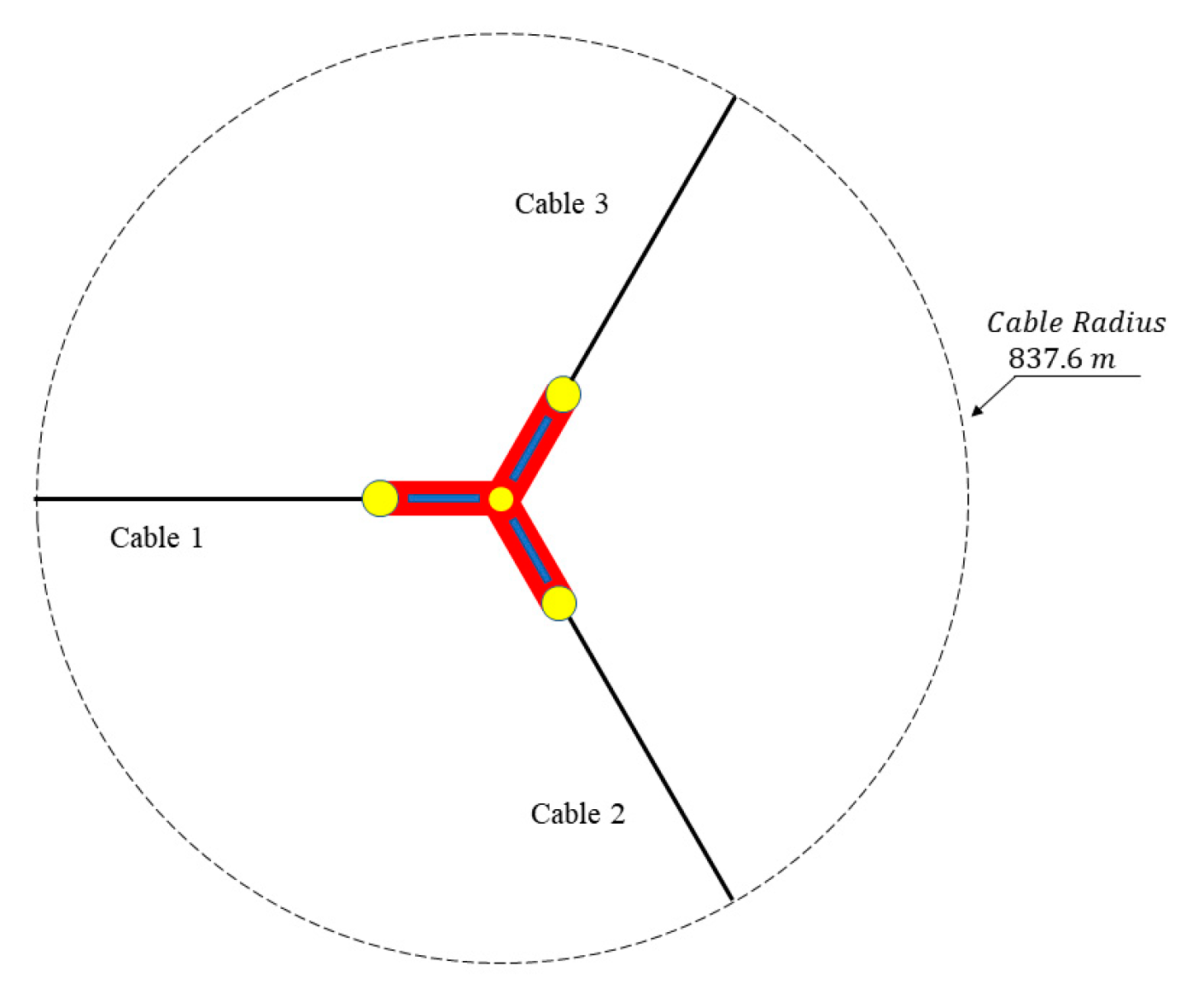
3.1. Semi-Submersible Platform and Mooring Design Parameters

The wind-wave hybrid power generation platform primarily relies on the reciprocating motion of the oscillating flap driven by waves to generate electricity. To study this coupled motion, this paper first conducted geometric modeling of the floating foundation and the oscillating flap-type wave energy converter. The floating foundation is the UMaine VolturnUS-S platform [43], which supports a 15 MW wind turbine. This platform is a classic three-column semi-submersible design, with a central column diameter of 10 m and side column diameters of 12.5 m. Each side column consists of a 7 m-high buoyancy box at the bottom and a 28 m-high buoyant cylinder above. The central column of the platform supports the wind turbine tower. Specific mass and geometric parameters are shown in Table 1 and Figure 3.

3.2. Wind Turbine and Oscillating Flap-Type Design Model

The wind turbine selects 15 MW three-blade horizontal-axis wind turbine. The main design parameters of the wind turbine are shown in Table 2.
The flap-type wave energy converter harnesses the energy of ocean waves by utilizing the reciprocating motion induced by wave fluctuations. Due to the constraint imposed by the pivot axis on the oscillating flap-type wave energy converter, the coupling relationships between its degrees of freedom are altered. Therefore, the model in this study adopts a motion model with hinged constraints. The structure of the oscillating wave energy converter is shown in Figure 4a, where components such as the hydraulic motor, overflow valve, and throttle valve in the power generation system are abstracted as springs with constant stiffness and damping. The modeling diagram in AQWA is illustrated in Figure 4b. By applying the hinge constraint in the ‘Joint’ module, the oscillating plate is fixed at a stationary point, and the damping and stiffness for rotation are defined to simulate the PTO system of the oscillating wave energy converter.
First, a geometric model of flap-type wave energy converter is established, with a width of 30 m, a height of 13 m, and a thickness of 3 m. For specific parameters are shown in Table 3.

3.3. Array Oscillating Wind-Wave Combined Platform Model

The array distribution of oscillating flap-type wave energy converter is determined by the floating wind turbine foundation. The floating wind turbine foundation adopts a semi-submersible foundation, and the paddle is placed between two foundation buoys. Three paddles are arranged symmetrically. The specific layout parameters are shown in Table 4. The paddle is directly connected to the foundation through a connecting rod and the paddle shaft is nested on the buoy between the foundation buoys, as shown in Figure 5.

4. Result

4.1. Parameter Analysis of Flap-Type Wave Energy Converter

4.1.1. Comparative Validation of the Frequency-Domain Analysis Method for a Flap-Type Wave Energy Converter

To accurately calculate the dynamic response of the flap-type wave energy converter under the constraint system of the oscillating axis, this paper constructs a hinge constraint in the frequency domain through a hinge constraint matrix. The boundary condition constraint matrix is derived from the Equation (13):
G = 0 1 0 0 0 0 0 0 1
To validate the analytical method, the system’s PTO stiffness is set to 8.0 × 10⁷ N·m/rad and the PTO damping to 3.1 × 10⁶ N/m/(rad/s). Subsequently, the RAO under the frequency-domain fixed single-pendulum hinge constraint is obtained through Equation (13). This RAO incorporates the combined effects of wave forces from multiple directions while accounting for the reaction force of the oscillating axis on the flap-type wave energy converter, resulting in more precise outcomes. Figure 6 presents a comparison between the frequency-domain motion amplitude response operator under the frequency-domain hinge constraint and the AQWA fixed hinge time-domain results. The accuracy of the hinge frequency-domain calculation method is verified through multiple time-domain conditions. Therefore, the hinge constraint matrix method will be employed in subsequent sections of this paper to optimize the parameters of the flap-type wave energy converter.

4.1.2. Hydrodynamic Analysis of Flap-Type Wave Energy Converter

When the external excitation frequency is the same as or very close to the natural vibration frequency of the system, the response of the system to external excitation is manifested as large-amplitude vibration. This phenomenon is called resonance and the external excitation frequency currently is called resonance frequency.
The average period of the main waves in the South China Sea is mainly distributed between 6 and 10 s [44,45]. By adjusting parameters to make the natural frequency of the system near the wave frequency, the amplitude of the swing plate motion can be significantly increased. Since the paddle needs to be connected to the floating platform and placed in deep water later in this article, the effect of water depth on the natural frequency of the system is not considered. Without changing the geometric characteristics of the wobble plate, the parameters that affect the natural frequency of the PTO system mainly include the stiffness and draft of the PTO system. Therefore, the hydrodynamic coefficients of the swing plate with drafts of 6, 7, 8, 9, 10, 11, and 12 m were first calculated, mainly considering the 0° head-wave condition, and focusing on the surge and heave related to the motion of the swing plate and a pitch of three degrees of freedom, as shown in Figure 7. The hydrodynamic coefficient changes regularly with water depth. As the draft becomes deeper, the peak frequency of the pitching motion of the swing plate increases, from 0.66 rad/s to 0.71 rad/s; while the peak frequency of the pitching motion of the swing plate increases from 0.91 rad/s shrinks to 0.81 rad/s, but both peak values show an increasing trend.

4.1.3. Parameter Optimization of Flap-Type Wave Energy Converter

The natural frequency of the flap-type wave energy converter (FWEC) can be calculated by combining the hydrodynamic coefficients of the 6–12 m flap-type wave energy converter with the system’s PTO stiffness. In this study, the PTO system stiffness was set across 127 conditions, ranging from 0 to 1.25 × 10⁸ N·m (rad/s) with an interval of 1.0 × 10⁶ N·m (rad/s). The natural frequency of the OWEC was computed under these conditions, as shown in Figure 8. The results indicate that as the draft depth increases, the natural frequency decreases, while an increase in PTO system stiffness leads to an increase in natural frequency. Since the wave energy converter in this study is designed to be deployed on a floating wind turbine platform, where wind and waves exhibit coexistent characteristics higher wind speeds are typically accompanied by larger wave heights and longer periods, it is necessary to consider the coexistence of wind and waves. Considering the wind-wave correlation and the wave frequency of the South China Sea, when the draft depth is 8 m and the PTO system stiffness is between 3 × 10⁷ and 1.1 × 10⁸ N·m (rad/s), the system’s natural frequency is approximately 0.51–0.66 rad/s, aligning with the dominant average wave periods in the South China Sea. Consequently, subsequent parameter optimization will focus on PTO stiffness values within the range of 3 × 10⁷ to 1.1 × 10⁸ N·m (rad/s).
By determining the PTO stiffness of the system, the optimal damping for the PTO system can be derived using Equation (13). To verify the accuracy of the optimal damping, the power generation near this damping value was first calculated. For this analysis, an oscillating plate with an 8 m draft depth and PTO stiffness selected 8.0 × 10⁷ N·m/rad, resulting in a natural frequency of 0.61 rad/s. The power generation was computed for PTO damping values ranging from 2.0 × 10⁷–5 × 10⁷ N·m(rad/s) and frequencies from 0.51 to 0.81 rad/s. As shown in Figure 9, the maximum power output occurs around (0.61, 3.5 × 10⁷), where the damping value at the peak power matches the optimal damping derived from the formula, thus validating its accuracy. Consequently, in the subsequent optimization work, with the stiffness and draft depth determined, the optimal damping will be directly applied as the PTO system’s damping.
Based on the verification of the optimal damping, a parameter analysis was conducted for the oscillating wave energy converter under different draft depths and PTO system stiffness values. The PTO stiffness corresponding to natural frequencies within 0.51–0.66 rad/s (ranging from 3 × 10⁷ to 1.1 × 10⁸ N·m/rad) was grouped. For each group, the corresponding natural frequencies and optimal damping values were calculated, as shown in Table 5, which presents the PTO stiffness, natural frequencies, and optimal damping values for different drafts. Specifically, the PTO stiffness values and corresponding optimal damping for a draft of 8 m (ranging from 3 × 10⁷ to 1.1 × 10⁸ N·m (rad/s)) were provided. Power generation parameter analysis was then carried out under these conditions.
Through the exploration of optimal PTO stiffness under the above conditions, power generation and oscillating plate motion amplitude in the frequency domain are shown in Figure 10. At the same draft, the maximum motion amplitude and natural frequency of the oscillating plate decrease as the PTO stiffness increases, while the overall power generation increases with increasing PTO stiffness. When the PTO stiffness is 8 × 10⁷ N·m/rad and the PTO damping is 3.5 × 10⁷ N·m (rad/s), the peak performance primarily aligns with the dominant average wave periods in the South China Sea, ranging from 0.512 to 0.672 rad/s, achieving higher power generation. In summary, for this fixed oscillating wave energy converter, selecting an oscillating plate with an 8 m draft and configuring the system PTO with a stiffness of 8.0 × 10⁷ N·m/rad and damping of 3.5 × 10⁷ N·m (rad/s) can achieve optimal power generation performance.

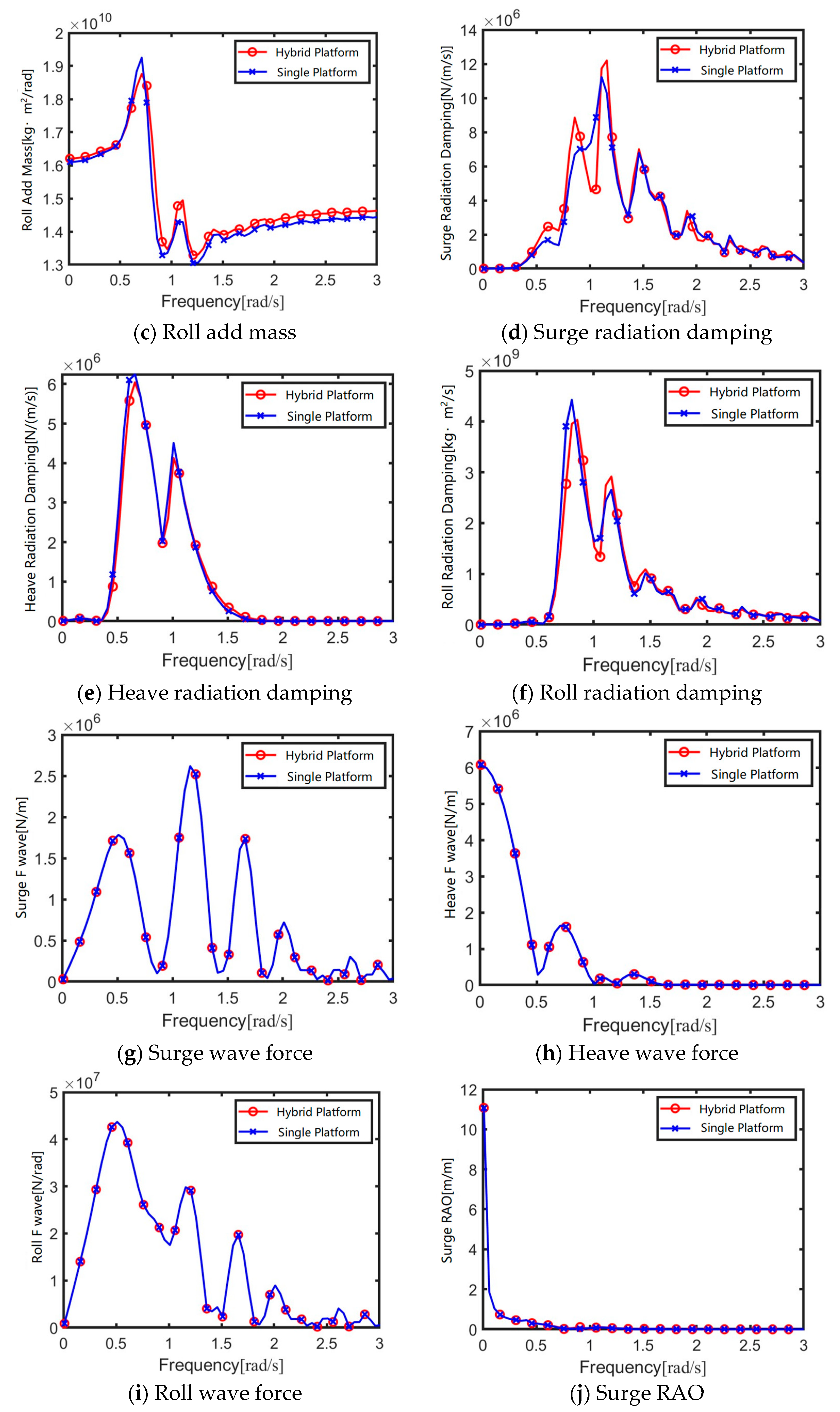
4.2. Hydrodynamic Analysis of Array Flap-Type WEC Combined Platform

In the analysis of multiple floating bodies, the potential flow theory neglects the effects of fluid viscosity and energy dissipation. Consequently, hydrodynamic interference occurs among the multiple floating bodies of a wind-wave coupled platform at certain frequencies, leading to hydrodynamic coefficients that differ from those of a single floating body. By selecting a wave direction of 90°, the focus is placed on the hydrodynamic coefficients in the sway, heave, and roll degrees of freedom.
Figure 11 presents a comparison of the hydrodynamic coefficients between the wind-wave coupled platform and the standalone platform. The overall trends of wave forces and RAOs are generally consistent for both. However, slight differences are observed in the added mass and radiation damping. In the sway direction, the wind-wave coupled platform exhibits distinct peaks in added mass and radiation damping, attributed to the presence of multiple wave energy converters within the platform. These close-proximity multibody hydrodynamic interactions cause variations, although their impact on the platform’s natural frequencies of motion is minimal.

4.3. Time Domain Coupling Analysis of Array Flap-Type WEC Combined Platform

4.3.1. Verification of Time Domain Analysis Method for Array Flap-Type Wave Energy Converter Combined Platform

To build a fully coupled model of the floating wind-wave combined platform, the hydrodynamic model of the floating platform and wave energy is first established in AQWA. The equivalent stiffness and damping in the PTO system are simulated by Joint in the time domain module and the catenary mooring system of AQWA is used. The upper structure load is simulated by calling OPENFAST through the user force of AQWA to realize the simulation of aerodynamic loads and structural dynamics. For the simulation of aerodynamic loads, the required wind speed time history curve is first generated by TURBSIM64, and then the real-time wind speed is imported into Aerodyn15 through the INFLOWWIND module to calculate the real-time load of the blade node; for the simulation of structural dynamics, the dynamic response model of flexible components such as blades and towers is established through the modal superposition method and Kane equation, and the displacement and load of each node of the structure are calculated in the ELASTDYN module of OPENFAST. Finally, the aerodynamic-elastic-hydrodynamic-PTO-mooring fully coupled model of the floating wind-wave combined platform is constructed, as shown in Figure 12.
The rated power condition was selected for comparison and verification. The inflow wind was selected to be a steady wind of 10.59 m/s and waves and currents were not considered. The six degrees of freedom motion response of the floating wind-wave platform in F2A and OPENFAST were calculated and compared and verified.
Figure 13 shows the comparison results of the six degrees of freedom motion response of the fully coupled time-domain model of the floating wind-wave platform calculated in F2A and OPENFAST. The platform sway gradually reaches the equilibrium position after 800 s, and the sway displacement at the equilibrium position is about 20 m; there are certain differences in the platform sway, roll, and bow roll, but the amplitudes of both are very small and have almost no effect; the amplitude of the platform heave calculated by F2A is slightly larger than that of OPENFAST and the equilibrium position is basically the same; the platform pitch also gradually reaches the equilibrium position after 200 s and the average pitch is about 2.1°. Although OPENFAST and F2A are not completely consistent in the prediction of the motion response of the floating wind-wave platform, their equilibrium positions and motion periods are consistent. Therefore, it can be considered that the calculation of the floating wind-wave platform (without wave energy converter) in F2A has a certain accuracy. For floating wind-wave platforms involving multiple bodies, F2A can replace OPENFAST for fully coupled time-domain calculations.

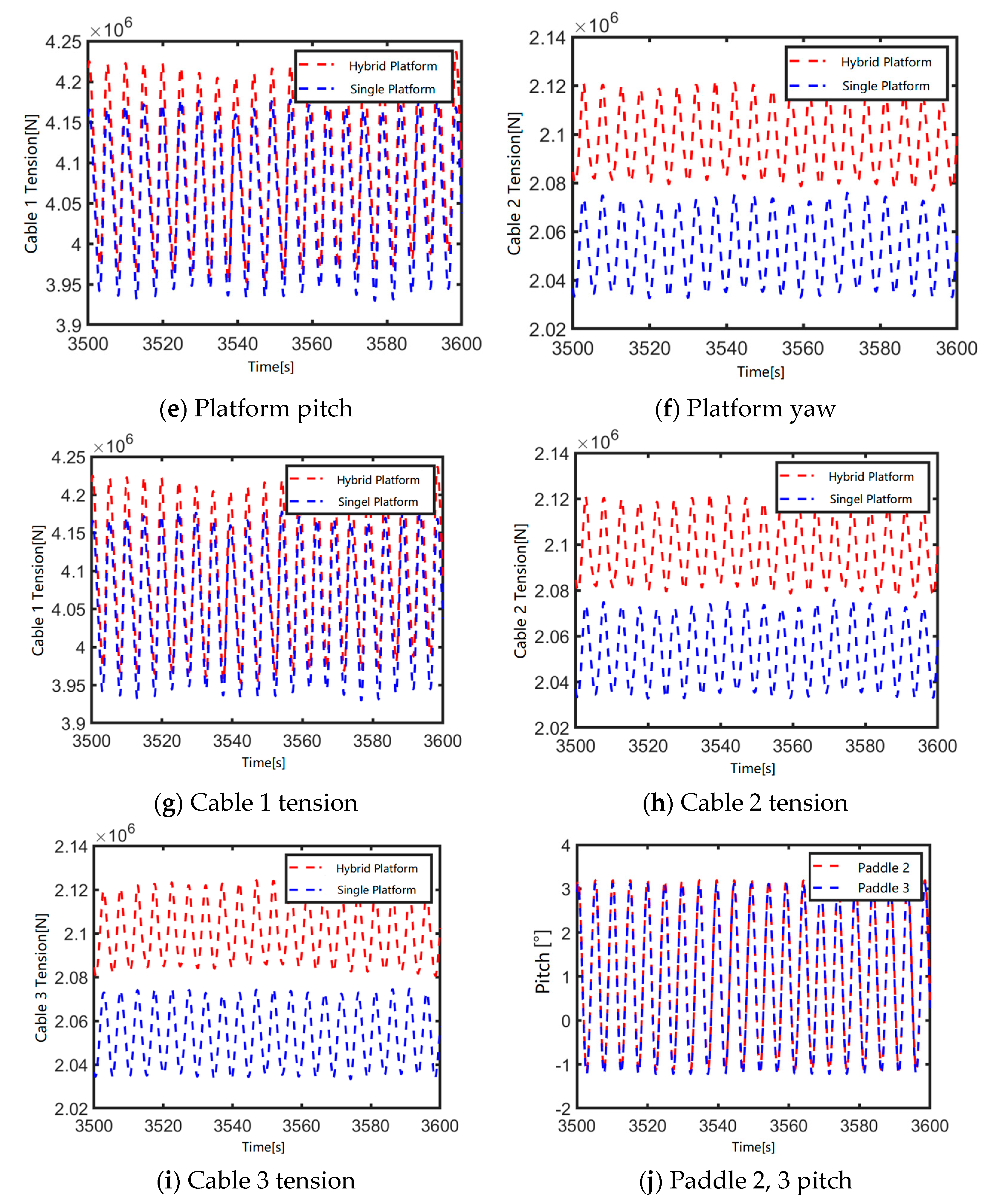
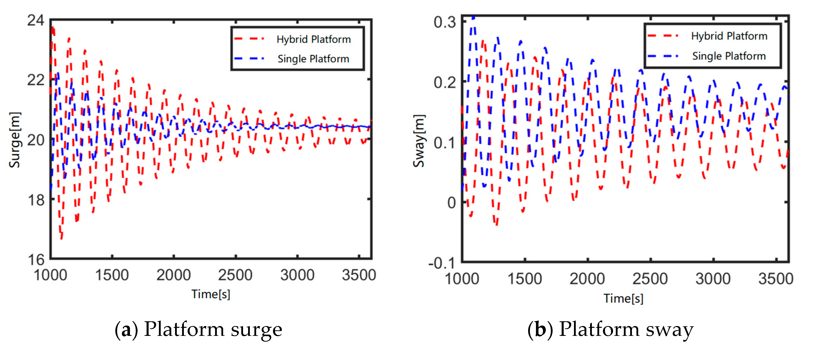
4.3.2. Motion and Mooring Analysis of an Array Flap-Type Wave Energy Converter Combined Platform

The preliminary mooring scheme adopts the official mooring scheme of the 15 MW semi-submersible platform. The three catenaries are symmetrically distributed about the center of the platform’s Z axis. The fair lead hole is located on the column 14.0 m below the still water surface, with a radius of 59.25 m from the center line of the platform. The anchor is located 200 m below the still water surface, with a radius of 837.6 m from the center line of the platform. One of the lines points to the negative X axis. The remaining two cables are evenly distributed around the platform and each cable is 120° apart. The parameters related to the mooring cable are shown in Table 6 and the mooring scheme layout is shown in Figure 14.
The study in this section does not consider the wind turbine structure above the floating wind turbine but only considers the influence of the swing wave energy on the platform motion response and mooring tension. The verification condition is set as a wave frequency of 0.61 rad/s, a wave direction of 0° and 90°, a wave height of 1 m regular wave, and no consideration of wind and current.
Figure 15 shows the motion response comparison results of the floating wind-wave platform with or without a wave energy device under 0° wave conditions. It can be seen from the figure that the presence or absence of a wave energy device has little effect on the equilibrium position of the platform’s sway and pitch, but the presence of a wave energy device makes the platform’s sway more difficult to balance and the platform’s pitch is reduced. This is because the load of the wave energy device’s pendulum in the waves causes the platform to perform non-pure periodic motion, and at the same time, the reaction force of the wave energy device reduces the platform’s pitch motion. There are certain differences in the platform’s heave motion, mainly because the floating wind-wave platform has a larger total displacement due to the displacement of the wave energy device, and the heave equilibrium position has risen by about 0.5 m. The mooring tension basically shows a similar trend to the platform’s sway. The presence of a wave energy device has a greater change in the mooring tension, but the amplitude of the mooring tension becomes smaller and is enveloped by the mooring tension of the floating platform without a wave energy device. In addition, under 0° wave conditions, the pitch amplitude of the second and third pendulum plates is 0.21 rad.
Figure 16 shows the motion response comparison results of the floating wind-wave combined platform with or without a wave energy device under 90° waves. It can be seen from the figure that the effects of the wave energy device on the platform’s sway, heave and roll under 90° waves are like those under 0° waves. The amplitude of the pitch motion of the floating platform with a wave energy device is slightly larger, which is due to the influence of the force generated by the swing plate movement of the wave energy device on the platform. The mooring tension has a large change. The tension of cable 2 is the largest under 90° waves and as the main tension mooring cable in the transverse wave direction, the mooring tension of cable 2 is the largest. The mooring tension means of the cable 1 and cable 3 are similar, but the cable 1 tension of the floating wind-wave combined platform with a wave energy device is smaller and the cable 3 shows the opposite trend, which is caused by the swing plate movement of the wave energy device. In addition, when the wave is facing downward at 90°, the pitch motion amplitude of paddle 1 of the wave energy device is the largest, with a maximum value of 0.21 rad; when paddle 2 and paddle 3 change from facing the wave at 60° to facing the wave at 30°, the pitch motion amplitude of the pendulum plates is only 0.09 rad.

4.3.3. Fully Coupled Motion Response of an Array Flap-Type Wave Energy Converter Combined Platform

The previous section investigated the impact of the presence or absence of wave energy devices on the motion response of a floating wind-wave hybrid platform, without considering the effects of aerodynamic loads from the upper structure. Based on the content discussed earlier, this section employs the F2A method to evaluate the influence of full coupled aero-hydro-servo-elastic-PTO-mooring dynamic analysis interactions on platform motion responses and mooring tension with and without wave energy devices. The inflow wind speed is set at the rated value of 10.59 m/s, while the wave conditions involve regular waves with a wave direction of 0° and a wave height of 1 m. Wave frequencies are selected sequentially as 0.61 rad/s, 1.4 rad/s, and 1.8 rad/s, corresponding to the maximum power generation and the most common wave conditions in the South China Sea, to assess the effects of wave energy devices on platform motion responses and mooring tension. The simulation duration is set to 3600 s, with the first 500 s of data discarded to mitigate the transient effects caused by the startup of the floating wind turbine.
Figure 17 presents a comparison of the six degrees of freedom (6-DOF) motion responses and mooring tensions of the floating wind-wave platform with and without wave energy devices at a wave frequency of 0.61 rad/s. Under conditions considering the upper structure, the presence or absence of wave energy devices has negligible impact on the surge and sway motions of the platform. However, it significantly affects the heave motion, as the increased weight of the upper structure deepens the draft of the floating wind-wave hybrid platform, resulting in a 1.5 m difference in the equilibrium position of the heave motion between the configurations with and without wave energy devices. The inclusion of wave energy devices effectively suppresses the rotational degrees of freedom, with the roll, pitch, and yaw motions of the hybrid platform being smaller than those of the standalone floating platform. Additionally, with the inclusion of aerodynamic loads, the mooring tension of the wind-wave hybrid platform exceeds that of the standalone floating platform. Cable 1 positioned in the windward and wave ward direction experiences the highest tension, with a peak value of 4.11 × 10⁶ N at equilibrium, which is 50 kN greater than that of cable 1 on the standalone floating platform. Meanwhile, the tension curves of cable 2 and 3 are nearly identical, with the mooring tension of the hybrid platform exceeding that of the standalone platform by 58 kN.
Figure 18 and Figure 19 show the six degrees of freedom motion response and mooring tension comparison results of the floating wind-wave combined platform with and without wave energy devices under the two most common waves in the South China Sea. As the wave period becomes shorter, there are slight differences in the platform surge and sway motion with and without wave energy devices. The amplitude of the surge and sway motion of the floating wind-wave combined platform is greater than that of the single floating platform, but the offset of the equilibrium position is smaller than that of the single floating platform. This is because the period of the platform surge and sway motion caused by the wave energy device becomes longer and the motion amplitude is larger. The difference between the platform heave and pitch motion is consistent. The offset of the motion equilibrium position does not vary much with the wave frequency, but as the wave period becomes shorter, the equilibrium position is reached faster. The cable tension does not vary much with the wave period, mainly because the aerodynamic load of the upper wind turbine is the main factor affecting the change of the cable tension in the working condition considering the superstructure. Under the same wave load, the tension of the cable 1 considering the superstructure and aerodynamic load is 60.3% higher than that of the cable 1 considering only the platform wave load; the change of mooring tension caused by wave load is only a slight change within the same order of magnitude. In the pitch motion response of the paddle, as the wave period becomes shorter, the pitch amplitude of the paddle becomes smaller. This is because at the same wave height, as the wave frequency increases, it exceeds the natural frequency of the wave energy device, causing the pitch motion response amplitude to decrease.

5. Conclusions

This section focuses on the dynamic response analysis of the floating wind-wave hybrid platform. Firstly, a frequency-domain analysis and parameter optimization of a fixed oscillating wave energy converter were conducted. A geometric model of a single oscillating wave energy converter was established using AQWA, followed by a hydrodynamic analysis in the frequency domain. The hydrodynamic analysis was carried out on the paddles with drafts of 6–12 m and the natural frequencies and other characteristics of the swing plates under different drafts were compared. Then, the optimization boundary conditions were specified according to the sea conditions in the South China Sea and the approximate optimization range of PTO was obtained through the dual-parameter optimization method of draft and PTO stiffness. At the same time, the verification of the optimal damping was carried out. Based on the approximate optimization range of PTO, the average power generation in the frequency domain was calculated for the swing plates with different drafts and the optimal draft and PTO parameters were obtained. The results show that when the draft is 8 m, the PTO system is 8.0 × 10⁷ N·m/rad, and the PTO damping takes the optimal damping, it has a higher power generation capacity. Based on the hydrodynamic analysis results of the wind-wave combined platform, the hydrodynamic interference between multiple bodies induced by the coupled wave energy device causes variations in the peak values of added mass and radiation damping in the sway direction. However, these effects have negligible influence on the natural frequency of the platform’s motion.
Then, the F2A method was selected to construct a fully coupled time-domain model of the floating wind-wave platform. First, the motion response characteristics of the floating wind-wave platform without wave energy devices in F2A and OPENFAST were compared to prove the accuracy of the F2A method. Then, without considering the upper wind turbine structure, the motion response and mooring analysis of the floating wind-wave platform with and without wave energy devices were carried out to explore the influence of the oscillating wave energy device on the motion response characteristics of the floating platform; then, the influence of the presence or absence of wave energy devices on the fully coupled motion response of the floating wind-wave platform was explored and the influence of the coupling effect of the wave energy device and the upper wind turbine structure on the platform motion response was clarified.
From the results, without considering the upper wind turbine structure of the floating wind turbine, the wave energy device has little effect on the equilibrium position of the platform’s surge and pitch, but the presence of the wave energy device will make the platform’s surge more difficult to balance, the platform’s pitch is reduced, and there is a certain difference in the platform’s heave. After the introduction of the upper wind turbine, the wave energy device has almost no effect on the platform’s surge and sway motion but can effectively suppress the movement of the floating wind and wave combined with platform’s sway degrees of freedom. The roll, pitch, and yaw motions of the floating wind and wave combined platform are all smaller than those of a single floating platform.
It should be noted that the main content of this paper is the selection of the optimal damping for the wave energy converter PTO and the influence of the wave energy converter on the wind-wave combined platform. In the future, the mooring design of the wind-wave combined platform under different sea conditions can be optimized. Moreover, the wind-wave combined platform proposed in this paper is at the preliminary design analysis stage and has not yet carried out experimental simulation or motion response analysis under more complex sea conditions.

Author Contributions

Conceptualization, Y.Y. and C.L. (Chenyu Liang); methodology, M.C. and T.T.; software, Y.Y., M.C. and C.L. (Chenyu Liang); validation, C.L. (Chenyu Liang), M.C. and S.L.; formal analysis, J.J.; investigation, Y.Y. and C.L. (Chenyu Liang); resources, S.L. and Y.Y.; data curation, J.J.; writing—original draft preparation, C.L. (Chenyu Liang); writing—review and editing, S.L., Z.H. and C.L. (Chenyu Liang); visualization, C.L. (Chonggan Liang); supervision, M.C. and W.O.; project administration, Y.Y., S.L. and T.T.; funding acquisition, S.L., Y. Y. and M.C. All authors have read and agreed to the published version of the manuscript.

Funding

This research was funded by the Key technology research and demonstration project of 10 MW deep-sea floating offshore wind turbine (DTGD-2023-10174)—Key technology research task of floating offshore combined wind and wave power generation. And this research was also funded by the National Natural Science Foundation of China, grant number 52171275. The financial support is greatly appreciated.

Institutional Review Board Statement

Not applicable.

Informed Consent Statement

Not applicable.

Data Availability Statement

Data are contained within the article.

Conflicts of Interest

Authors Yi Yang, Shi Liu, Zheng Huang, Chonggan Liang, Wenjun Ou, and Tao Tao were employed by the company China Southern Power Grid Technology Co., Ltd. Author Zheng Huang was employed by the company National Institute of Guangdong Advanced Energy Storage Co., Ltd. The remaining authors declare that the research was conducted in the absence of any commercial or financial relationships that could be conducted as a potential conflict of interest.

References

  1. Rebecca Williams, F.Z. Global Offshore Wind Report 2023; Global Wind Energy Council: Brussels, Belgium, 2023. [Google Scholar]
  2. Bossler, A. Floating Offshore Wind Foundations: Industry Projects in the USA, Europe and Japan; Technical Report; Maine International Consulting, Inc.: Bremen, USA, 2011. [Google Scholar]
  3. Lefebvre, S.; Collu, M. Preliminary design of a floating support structure for a 5 MW offshore wind turbine. Ocean Eng. 2012, 40, 15–26. [Google Scholar] [CrossRef]
  4. Ahn, H.; Ha, Y.-J.; Cho, S.-G.; Lim, C.-H.; Kim, K.-H. A Numerical Study on the Performance Evaluation of a Semi-Type Floating Offshore Wind Turbine System According to the Direction of the Incoming Waves. Energies 2022, 15, 5485. [Google Scholar] [CrossRef]
  5. Johannessen, M. Concept Study and Design of Floating Offshore Wind Turbine Support Structure. Master’s Thesis, KTH Royal Institute of Technology, Stockholm, Sweden, 2018. [Google Scholar]
  6. Liu, Y.; Hu, C.; Sueyoshi, M.; Yoshida, S.; Iwashita, H.; Kashiwagi, M. Motion response characteristics of a Kyushu-University semi-submersible floating wind turbine with trussed slender structures: Experiment vs. numerical simulation. Ocean Eng. 2021, 232, 109078. [Google Scholar] [CrossRef]
  7. Meng, H.; Liu, Y.; Tian, D.; Long, K.; Su, Y.; Li, B.; Sun, K. A novel conceptual design of a semi-submersible foundation for a 15 MW floating wind turbine. Ocean Eng. 2024, 294, 116726. [Google Scholar] [CrossRef]
  8. Psomas, P.M.; Platis, A.N.; Koutras, V.P.; Dagkinis, I.K. Intermittent system utilization for an efficient maintenance planning of offshore wind turbine rotor blades. Ocean Eng. 2025, 318, 120181. [Google Scholar] [CrossRef]
  9. Chatterjee, S.; Byun, Y.-C. Leveraging generative adversarial networks for data augmentation to improve fault detection in wind turbines with imbalanced data. Results Eng. 2025, 25, 103991. [Google Scholar] [CrossRef]
  10. Zou, Q.; Lu, Z.; Shen, Y. Short-term prediction of hydrodynamic response of a novel semi-submersible FOWT platform under wind, current and wave loads. Ocean Eng. 2023, 278, 114471. [Google Scholar] [CrossRef]
  11. Hu, Y.; Luo, P.; Yao, W.; Zhou, L.; Shi, P.; Yang, W.; Han, H. Power increase and lifespan extension control strategy of wind turbine yaw system based on power loss. Sustain. Energy Technol. Assess. 2025, 74, 104172. [Google Scholar] [CrossRef]
  12. Wan, L.; Moan, T.; Gao, Z.; Shi, W. A review on the technical development of combined wind and wave energy conversion systems. Energy 2024, 294, 130885. [Google Scholar] [CrossRef]
  13. Chen, M.; Deng, J.; Yang, Y.; Zhou, H.; Tao, T.; Liu, S.; Sun, L.; Hua, L. Performance Analysis of a Floating Wind–Wave Power Generation Platform Based on the Frequency Domain Model. J. Mar. Sci. Eng. 2024, 12, 206. [Google Scholar] [CrossRef]
  14. Chen, M.; Yun, Q.; Hallak, T.; Zhou, H.; Zhang, K.; Yang, Y.; Tao, T.; Liu, S.; Jiang, W.; Li, C. Comparative Study on the Performances of a Hinged Flap-Type Wave Energy Converter Considering Both Fixed and Floating Bases. J. Mar. Sci. Eng. 2024, 12, 1416. [Google Scholar] [CrossRef]
  15. Zhang, X.; Li, B.; Hu, Z.; Deng, J.; Xiao, P.; Chen, M. Research on Size Optimization of Wave Energy Converters Based on a Floating Wind-Wave Combined Power Generation Platform. Energies 2022, 15, 8681. [Google Scholar] [CrossRef]
  16. Tian, Z.; Shi, W.; Li, X.; Park, Y.; Jiang, Z.; Wu, J. Numerical simulations of floating offshore wind turbines with shared mooring under current-only conditions. Renew. Energy 2025, 238, 121918. [Google Scholar] [CrossRef]
  17. Michailides, C.; Gao, Z.; Moan, T. Experimental and numerical study of the response of the offshore combined wind/wave energy concept SFC in extreme environmental conditions. Mar. Struct. 2016, 50, 35–54. [Google Scholar] [CrossRef]
  18. Michailides, C.; Luan, C.; Gao, Z.; Moan, T. Effect of Flap Type Wave Energy Converters on the Response of a Semi-Submersible Wind Turbine in Operational Conditions. In Proceedings of the ASME 2014 33rd International Conference on Ocean, Offshore and Arctic Engineering, San Francisco, CA, USA, 8–13 June 2014. [Google Scholar]
  19. Wang, T.; Zhu, K.; Cao, F.; Li, D.; Gong, H.; Li, Y.; Shi, H. A coupling framework between OpenFAST and WEC-Sim. Part I: Validation and dynamic response analysis of IEA-15-MW-UMaine FOWT. Renew. Energy 2024, 225, 120249. [Google Scholar] [CrossRef]
  20. Wan, L.; Gao, Z.; Moan, T.; Lugni, C. Experimental and numerical comparisons of hydrodynamic responses for a combined wind and wave energy converter concept under operational conditions. Renew. Energy 2016, 93, 87–100. [Google Scholar] [CrossRef]
  21. Wan, L.; Gao, Z.; Moan, T.; Lugni, C. Comparative experimental study of the survivability of a combined wind and wave energy converter in two testing facilities. Ocean Eng. 2016, 111, 82–94. [Google Scholar] [CrossRef]
  22. Luan, C.; Michailides, C.; Gao, Z.; Moan, T. Modeling and Analysis of a 5 MW Semi-Submersible Wind Turbine Combined with Three Flap-Type Wave Energy Converters. In Proceedings of the ASME 2014 33rd International Conference on Ocean, Offshore and Arctic Engineering, San Francisco, CA, USA, 8–13 June 2014. [Google Scholar]
  23. Li, C.B.; Zhang, Z.; Zhang, J.; Li, X.; Choung, J.; Chen, M. Investigation on local mooring stresses of floating offshore wind turbines considering mooring chain geometrical and material nonlinearity. Ocean Eng. 2024, 312, 119166. [Google Scholar] [CrossRef]
  24. Bachynski, E.E.; Moan, T. Point Absorber Design for a Combined Wind and Wave Energy Converter on a Tension-Leg Support Structure. In Proceedings of the International Conference on Offshore Mechanics and Arctic Engineering, Nantes, France, 8–13 June 2013. [Google Scholar]
  25. Yang, Y.; Bashir, M.; Michailides, C.; Li, C.; Wang, J. Development and application of an aero-hydro-servo-elastic coupling framework for analysis of floating offshore wind turbines. Renew. Energy 2020, 161, 606–625. [Google Scholar] [CrossRef]
  26. Yang, Y.; Bashir, M.; Wang, J.; Yu, J.; Li, C. Performance evaluation of an integrated floating energy system based on coupled analysis. Energy Convers. Manag. 2020, 223, 113308. [Google Scholar] [CrossRef]
  27. Chen, M.; Xiao, P.; Zhou, H.; Li, C.B.; Zhang, X. Fully coupled analysis of an integrated floating wind-wave power generation platform in operational sea-states. Front. Energy Res. 2022, 10, 931057. [Google Scholar] [CrossRef]
  28. Chen, M.; Huang, W.; Liu, H.; Hallak, T.S.; Liu, S.; Yang, Y.; Tao, T.; Jiang, Y. A novel SPM wind-wave-aquaculture system: Concept design and fully coupled dynamic analysis. Ocean Eng. 2025, 315, 119798. [Google Scholar] [CrossRef]
  29. Jiang, W.; Liang, C.; Tao, T.; Yang, Y.; Liu, S.; Deng, J.; Chen, M. Fully Coupled Analysis of a 10 MW Floating Wind Turbine Integrated with Multiple Wave Energy Converters for Joint Wind and Wave Utilization. Sustainability 2024, 16, 9172. [Google Scholar] [CrossRef]
  30. Tian, W.; Wang, Y.; Shi, W.; Michailides, C.; Wan, L.; Chen, M. Numerical study of hydrodynamic responses for a combined concept of semisubmersible wind turbine and different layouts of a wave energy converter. Ocean Eng. 2023, 272, 113824. [Google Scholar] [CrossRef]
  31. Jin, P.; Zheng, Z.; Zhou, Z.; Zhou, B.; Wang, L.; Yang, Y.; Liu, Y. Optimization and evaluation of a semi-submersible wind turbine and oscillating body wave energy converters hybrid system. Energy 2023, 282, 128889. [Google Scholar] [CrossRef]
  32. Zhang, D.; Chen, Z.; Liu, X.; Sun, J.; Yu, H.; Zeng, W.; Ying, Y.; Sun, Y.; Cui, L.; Yang, S.; et al. A coupled numerical framework for hybrid floating offshore wind turbine and oscillating water column wave energy converters. Energy Convers. Manag. 2022, 267, 115933. [Google Scholar] [CrossRef]
  33. Cao, F.; Yu, M.; Han, M.; Liu, B.; Wei, Z.; Jiang, J.; Tian, H.; Shi, H.; Li, Y. WECs microarray effect on the coupled dynamic response and power performance of a floating combined wind and wave energy system. Renew. Energy 2023, 219, 119476. [Google Scholar] [CrossRef]
  34. Liu, M.; Zhang, X.; Fatikow, S. Design and analysis of a high-accuracy flexure hinge. Rev. Sci. Instrum. 2016, 87, 055106. [Google Scholar] [CrossRef]
  35. ANSYS. AQWA Theory Manual; AQWA: Canonsburg, PA, USA, 2023. [Google Scholar]
  36. Cummins, W.E. The Impulse Response Function and Ship Motions; Department of the Navy, David Taylor Model Basin: West Bethesda, MD, USA, 2010. [Google Scholar]
  37. Taghipour, R.; Perez, T.; Moan, T. Hybrid frequency–time domain models for dynamic response analysis of marine structures. Ocean Eng. 2008, 35, 685–705. [Google Scholar] [CrossRef]
  38. Zou, M.; Chen, M.; Zhu, L.; Yun, Q.; Zhao, W.; Liang, Q.; Zhao, Y. Experimental and numerical investigation of gap resonances between side-by-side fixed barges under beam sea excitation. Ocean Eng. 2024, 297, 117150. [Google Scholar] [CrossRef]
  39. Zou, M.; Chen, M.; Zhu, L.; Li, L.; Zhao, W. A constant parameter time domain model for dynamic modelling of multi-body system with strong hydrodynamic interactions. Ocean Eng. 2023, 268, 113376. [Google Scholar] [CrossRef]
  40. Chen, M.; Jiang, J.; Zhang, W.; Li, C.B.; Zhou, H.; Jiang, Y.; Sun, X. Study on Mooring Design of 15 MW Floating Wind Turbines in South China Sea. J. Mar. Sci. Eng. 2024, 12, 33. [Google Scholar] [CrossRef]
  41. Liang, H.; Qiao, D.; Wang, X.; Zhi, G.; Yan, J.; Ning, D.; Ou, J. Energy capture optimization of heave oscillating buoy wave energy converter based on model predictive control. Ocean Eng. 2023, 268, 113402. [Google Scholar] [CrossRef]
  42. Liu, Z.; Zhao, J.; Lin, X. Effects of mooring line failure on semi-submersible wind turbine and the study of its mitigation measures. Ocean Eng. 2024, 311, 118889. [Google Scholar] [CrossRef]
  43. Allen, C.K.; Viscelli, A.; Dagher, H.J.; Goupee, A.J.; Gaertner, E.; Abbas, N.J.; Hall, M.; Barter, G.E. Definition of the UMaine VolturnUS-S Reference Platform Developed for the IEA Wind 15-Megawatt Offshore Reference Wind Turbine; National Renewable Energy Laboratory (NREL): Golden, CO, USA, 2020.
  44. Zhou, Y.; Ye, Q.; Shi, W.; Yang, B.; Song, Z.; Yan, D. Wave characteristics in the nearshore waters of Sanmen bay. Appl. Ocean Res. 2020, 101, 102236. [Google Scholar] [CrossRef]
  45. Hongxia, C.; Feng, H.; Ye-li, Y. Seasonal Characteristics and Temporal Variations of Ocean Wave in the Chinese Offshore Waters and Adjacent Sea Areas. Adv. Mar. Sci. 2006, 24, 407. [Google Scholar]
Figure 1. Main foundation types for floating wind turbines.
Sustainability 17 02448 g001
Figure 2. The coupling step relationship between AQWA and OPENFAST.
Sustainability 17 02448 g002
Figure 3. OO-Star three-column semi-submersible floating foundation.
Sustainability 17 02448 g003
Figure 4. Oscillating flap-type wave energy converter.
Sustainability 17 02448 g004
Figure 5. Schematic diagram of the floating wind-wave combined platform.
Sustainability 17 02448 g005
Figure 6. Comparison between frequency-domain hinge and AQWA fixed hinge time-domain results.
Sustainability 17 02448 g006
Figure 7. Hydrodynamic analysis of the wave energy swing plates at different drafts.
Sustainability 17 02448 g007aSustainability 17 02448 g007bSustainability 17 02448 g007c
Figure 8. Relationship between PTO stiffness and natural frequency.
Sustainability 17 02448 g008
Figure 9. Relationship between PTO damping and wave frequency.
Sustainability 17 02448 g009
Figure 10. Optimal PTO stiffness study.
Sustainability 17 02448 g010
Figure 11. Comparison of hydrodynamic coefficients between a wind-wave coupled platform and standalone platform.
Sustainability 17 02448 g011aSustainability 17 02448 g011bSustainability 17 02448 g011c
Figure 12. Fully coupled dynamic response model of a floating wind-wave combined platform.
Sustainability 17 02448 g012
Figure 13. Comparison of six degrees of freedom motion responses of the floating platform.
Sustainability 17 02448 g013aSustainability 17 02448 g013b
Figure 14. Schematic diagram of the mooring arrangement of the floating wind-wave combined platform.
Sustainability 17 02448 g014
Figure 15. Analysis of the downward motion response of a floating wind-wave platform in 0° waves.
Sustainability 17 02448 g015
Figure 16. Analysis of the motion response of a floating wind-wave platform in 90° waves.
Sustainability 17 02448 g016aSustainability 17 02448 g016b
Figure 17. Analysis of fully coupled motion response of a floating wind-wave platform under a wave frequency of 0.61 rad/s.
Sustainability 17 02448 g017aSustainability 17 02448 g017b
Figure 18. Analysis of fully coupled motion response of a floating wind-wave platform under a wave frequency of 1.4 rad/s.
Sustainability 17 02448 g018aSustainability 17 02448 g018b
Figure 19. Analysis of fully coupled motion response of a floating wind-wave platform under a wave frequency of 1.8 rad/s.
Sustainability 17 02448 g019aSustainability 17 02448 g019b
Table 1. UMaine platform main mass parameters.
ParameterValue
Total mass (t)17,854
Distance from the center of mass to the water surface line (m)14.94
Ixx (kg·m2)1.251 × 10¹⁰
Iyy (kg·m2)1.251 × 10¹⁰
Izz (kg·m2)2.367 × 10¹⁰
Table 2. Main design parameters of the 15 MW wind turbine.
ParameterValue
Frequency/MW15
Number of Blades3
Rotor Diameters/m240
Hub Height/m150
Cut-in Wind Speed/(m/s)3
Cutting Wind Speed/(m/s)25
Rated Wind Speed/(m/s)10.59
Table 3. Geometric parameters of the paddles.
ParameterValue
Width (m)30
Height (m)13
Thickness (m)3
Ixx (kg·m2)1.362 × 10⁷
Iyy (kg·m2)6.957 × 10⁷
Izz (kg·m2)8.182 × 10⁷
Table 4. Flap-type wave energy converter main mass parameters.
PaddleParameterValue
Paddle 1Distance from oscillating axis to water plane13 m
Geometric center coordinates of paddle(24.625, 0, −1.5)
Deflection angle
Paddle 2Distance from oscillating axis to water plane13 m
Geometric center coordinates of paddle(12.3125, 21.326, −1.5)
Deflection angle
Paddle 3Distance from oscillating axis to water plane13 m
Geometric center coordinates of paddle(12.3125, −21.326, −1.5)
Deflection angle
Table 5. PTO stiffness, natural frequency, and optimal damping (draft = 8 m).
Draft (m)PTO Stiffness (N·m/rad)Natural Frequency (rad/s)Optimal Damping (N·m (rad/s))
83.0 × 1070.511.3 × 107
5.0 × 1070.562.3 × 107
8.0 × 1070.613.5 × 107
1.1 × 1080.664.8 × 107
Table 6. Parameters of the mooring system.
ParameterValue
Number of mooring lines3
Length of mooring line in an unstretched state850 m
Mooring line diameter0.185 m
Equivalent density685 kg/m
Equivalent ductile stiffness3270 MN
Transverse drag coefficient2
Tangential drag coefficient1.15
Additional mass coefficient1
Disclaimer/Publisher’s Note: The statements, opinions and data contained in all publications are solely those of the individual author(s) and contributor(s) and not of MDPI and/or the editor(s). MDPI and/or the editor(s) disclaim responsibility for any injury to people or property resulting from any ideas, methods, instructions or products referred to in the content.

