Article

Resilience Assessment Framework for High-Penetration Renewable Energy Power System

by
Dongyue Zhou
1,
Xueping Pan
1,
Xiaorong Sun
1,* and
Funian Hu
2
1
School of Electrical and Power Engineering, Hohai University, Nanjing 211100, China
2
School of Electrical Engineering and Automation, Jiangsu Normal University, Xuzhou 221116, China
*
Author to whom correspondence should be addressed.
Sustainability 2025, 17(5), 2058; https://doi.org/10.3390/su17052058
Submission received: 11 January 2025 / Revised: 21 February 2025 / Accepted: 25 February 2025 / Published: 27 February 2025
(This article belongs to the Section Energy Sustainability)

Abstract

:
The random and intermittent nature of renewable energy creates challenges for power systems to cope with sudden disturbances and extreme events. This study establishes a system network model and cascading failure model that consider the power flow relationship between different power sources, and then the impact of renewable energy on power system resilience is analyzed based on complex network theory. Furthermore, several resilience evaluation indexes are proposed from structural and functional perspectives. Using the system model, a resilience curve suitable for renewable energy power systems is proposed. The electrical degree centrality is used as the index to identify key nodes and simulate random attack and deliberate attack modes. The effectiveness of the evaluation method is verified on the IEEE 118-bus system using the typical time, different access ratios, and distribution characteristics of renewable energy. The results indicate that with high penetration of renewable energy, power systems’ resilience may decline by more than 20% in most cases.

1. Introduction

Power systems are frequently affected by natural disasters and human-caused damage, causing system failures and even blackouts [1,2]. With the continuous integration of renewable energy into power grids, its randomness and uncertainty make the safety and stability issues of power systems more complex. It was pointed out that the long-term power outages in Texas in 2021 [3] and the United Kingdom in 2019 [4,5] were partly caused by renewable energy developmental policies. Therefore, evaluating the resilience of renewable energy power systems and improving their resilience to extreme events have received considerable attention around the world [6].
Power system resilience refers to its ability to resist, adapt to, and recover quickly from low-probability and high-risk events [7]. When a power system is disturbed by extreme events, a series of changes will occur in its operating performance. The resilience triangular or resilience trapezoidal models are commonly used to describe these changes before, during, and after a disturbance. Resilience evaluation indicators include two aspects, which are impact degree and change rate of system performance [8,9,10,11,12,13,14,15,16]. In [8], the ratio of the resilience of a triangular or trapezoidal area after an event to the area of the target performance curve was used as an indicator, while in [9], the delivery function, which can be the network, connectivity, flow, or delay of the system, was defined for resilience computation, and the proportion of the delivery function recovered from its disrupted state was employed as an indicator. Meanwhile, in [10], a resilience metric that integrates the basic features of a resilience trapezoid is described. In [11,12,13,14,15,16], the impact degree and change speed of system performance were explored during different stages of an attack. These studies mainly focused on the evaluation of system performance, while the network structure and its inherent effects on system performance were ignored.
The complex network theory, which focuses on two aspects of structure and function, is a power tool to study the resilience of renewable energy power systems [17]. Structural resilience refers to whether the system can maintain its topological integrity during extreme events. State resilience refers to abnormal changes in power quantity (voltage, frequency, etc.) and the ability of the system to provide the required services during steady-state and dynamic stages. The resilience evaluation includes the largest component size [18], the vulnerability index represented by the loss of load [19], and the power transmission efficiency index [20]. To comprehensively evaluate the resilience of power systems, the authors of [21,22] proposed a comprehensive index from multiple dimensions such as temporal and spatial dependence as well as uncertainty in system operation. In addition, cascading failure analysis was provided in [23] to reflect an initial failure in one component inducing subsequent failures across power systems.
With the ongoing integration of renewable energy, the inherent randomness and intermittence of renewable energy will undermine the resilience of power systems. However, comprehensive research on resilience assessment for renewable energy power systems is relatively limited. Most existing studies focused more on specific disasters [1,2]; the general analysis methods suitable for broader environmental conditions are often neglected.
This paper proposes a general resilience evaluation framework suitable for renewable energy power systems. The resilience progress and the impacts of disaster severity on power systems are analyzed from the perspectives of infrastructure and function when the system is subjected to random or malicious events. The main contributions of this study can be summarized as follows:
(1)
This study extends traditional power system modeling by incorporating the effects of renewable energy. It considers the complementary generation characteristics of different power sources, and cascading failure from the randomness of renewable energy is studied based on complex network theory. A new resilience curve is proposed based on this model.
(2)
A resilience evaluation index system for renewable energy power systems is developed based on the largest cluster size, power flow entropy, and loss in power flow. Two attack modes of random disaster and deliberate disaster are introduced, offering a comprehensive framework for assessing system resilience and providing key insights into its robustness.
(3)
A key node identification method is developed based on the centrality index. Simulations are conducted to analyze system resilience under different renewable energy operation scenarios and different attack modes. This study examines the effects of attack timing, penetration levels, and integration locations of renewable energy, providing valuable guidance for the safe and stable operation of renewable energy power systems.
The remainder of this paper is organized as follows. Section 2 introduces the resilience evaluation framework of renewable energy power systems based on the network modeling method. Section 3 establishes a resilience evaluation index system from three perspectives of system topology, power flow distribution, and loss of load. In Section 4, the IEEE 118-bus system is used as a study case, its resilience is evaluated by considering power fluctuations of renewable energy, and specific conclusions are derived.

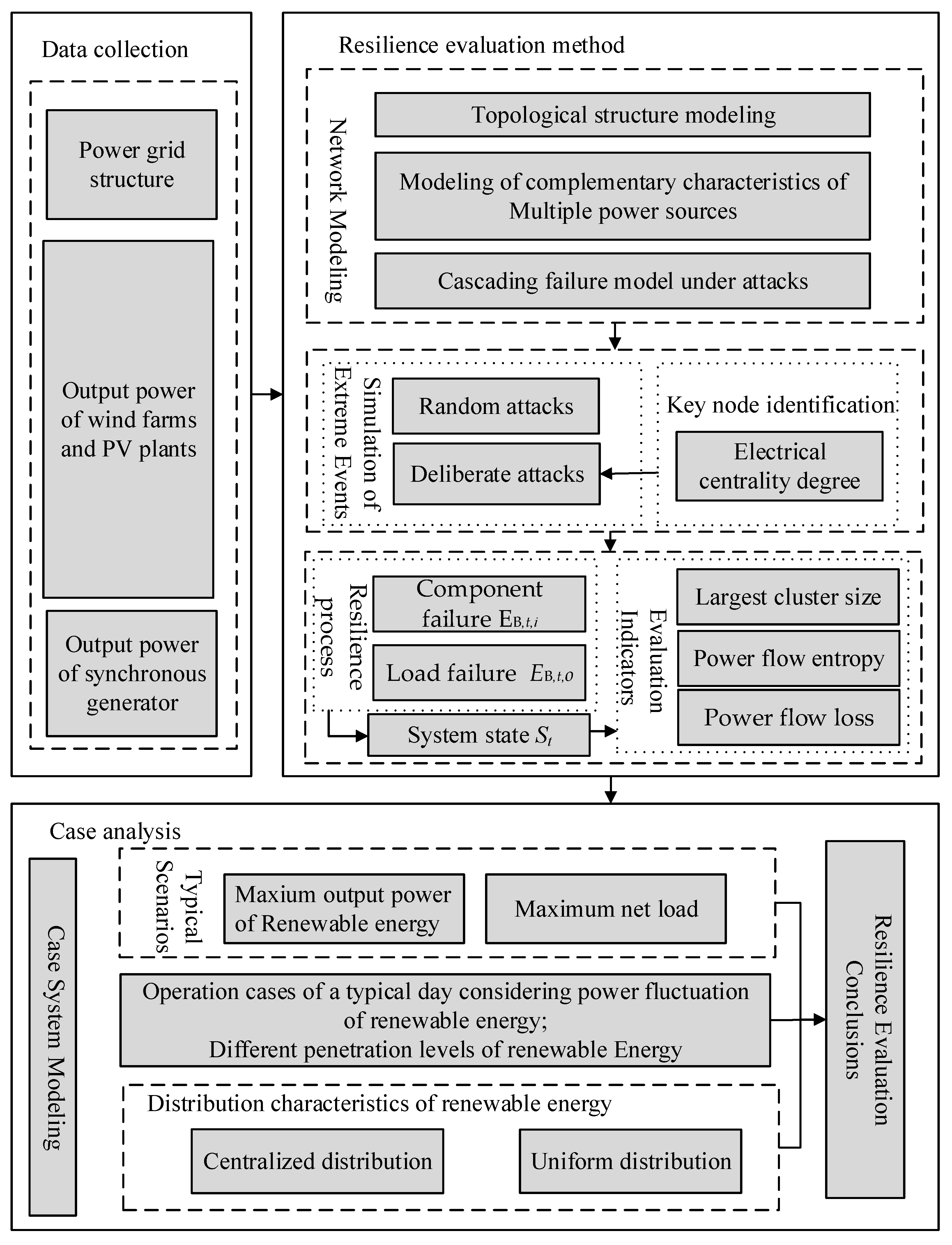
2. Resilience Evaluation Framework and Network Modeling

The IEEE 30-bus system shown in Figure 1 is taken as an example. In Figure 1, G represents the synchronous generator, PV stands for photovoltaic power, and W refers to wind power.
A new resilience curve is proposed based on complex network theory and from two perspectives of structure and function. A framework for the resilience analysis of renewable energy power systems is proposed.

2.1. Infrastructure and Operational Resilience Indexes

Infrastructure and operational resilience are two key factors for quantifying the performance of a system after an attack. Infrastructure resilience EB,t,i refers to the physical robustness required to mitigate the impact of damaged or nonfunctional components within the system. On the other hand, operational resilience EB,t,o represents the ability of a system to maintain uninterrupted in the face of a disaster. Specifically,
E B , t , i = N s , t N E B , t , o = P r , t P h
where Ns,t is the number of undamaged nodes, N is the total number of nodes, Pr,t is the actual output of the system, Ph is the total power output under normal operating conditions, subscript t represents time instant, and subscripts i and o represent infrastructure and operational resilience indexes, respectively.

2.2. Resilience Curve Based on Multi-Energy Complementary Characteristics

Resilience curves [24] are a powerful tool for the quantization of power system behaviors during disasters. A typical resilience curve includes three phases: the degradation stage (Phase I: tattb), recovery preparation stage (Phase II: tbttc), and recovery stage (Phase III: tcttd). The degradation stage refers to the process in which certain nodes are damaged after an event, changing the power flow distribution, resulting in cascading faults and considerable deterioration in system performance. Recovery preparation refers to the stage in which the system manager dispatches repair resources to the fault location. The recovery stage, on the other hand, involves repairing the system faults and subsequently restoring the power load supply.
For high-penetration renewable energy power systems, existing resilience curves suitable for the analysis of traditional power systems require enhancement and adaptation. The power fluctuation of renewable energy makes the system’s temporal characteristics much more complex. Although the degradation process of new energy power systems is similar to that of traditional power systems under an attack, structural changes due to load failure result in a resilience operational curve that shows a characteristic piecewise linearity in the variation of the load failure.
The performance of a renewable energy power system after extreme events is depicted in Figure 2.
Phase I: Degradation stage (tattb)
Suppose an attack occurs at time ta, causing the performance of the system to deteriorate. Due to the complementarity of different power sources, the performance declines at a relatively slow rate. Once the complementarity reaches its limit at ta1 (i.e., the redundancy of power sources can no longer compensate for the load demand), the decline of system performance will accelerate. The duration of Phase I is determined by the combined influence of attack duration and cascading failure duration.
Phase II: Recovery preparation stage (tbttc)
During Phase II, the power system enters a post-disturbance degraded state. The duration of this phase depends on the inspection time, which is influenced by the degree of system failure and environmental conditions.
Phase III: Recovery stage (tcttd)
During the recovery period, the power system will gradually be restored to its normal operation. Time td1 represents the recovery period where the system has not yet reached the redundancy of multi-energy complementarity, while the duration from td1 to td represents the recovery phase after the system has multi-energy complementarity capabilities.
The area ratio of the actual performance curve EB,t and expected performance curve ET,t within the time range {0, T} (T = td − ta) can be used to characterize the resilience of the system:
B ( T ) = 0 T E B , t d t / 0 T E T , t d t

2.3. Resilience Evaluation Framework

To quantitatively evaluate renewable energy power systems from multiple dimensions of infrastructure and function under different operational scenarios, a resilience evaluation framework that considers the complementary characteristics of renewable energy power systems is illustrated in Figure 3.
The evaluation framework in Figure 3 includes three parts, which are data collection, the resilience evaluation method, and the case study. The resilience evaluation indicators consist of the largest cluster size, power flow entropy, and loss in power flow. Two typical scenarios, a random attack and a deliberate attack, are considered, and the system resilience is calculated and discussed under different penetration ratios and integration distributions of renewable energy.

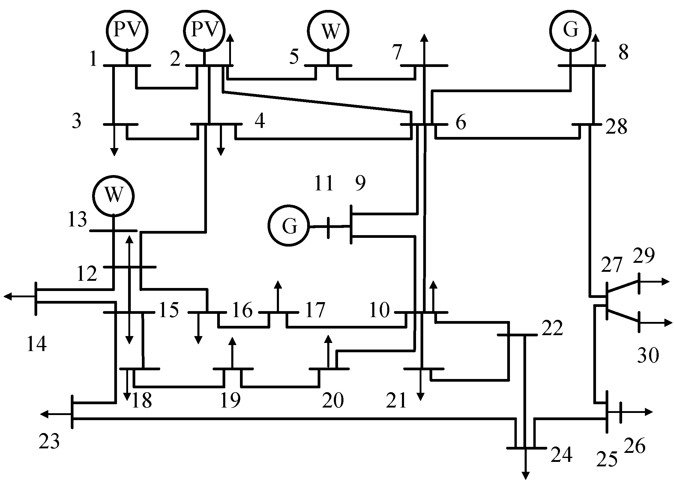
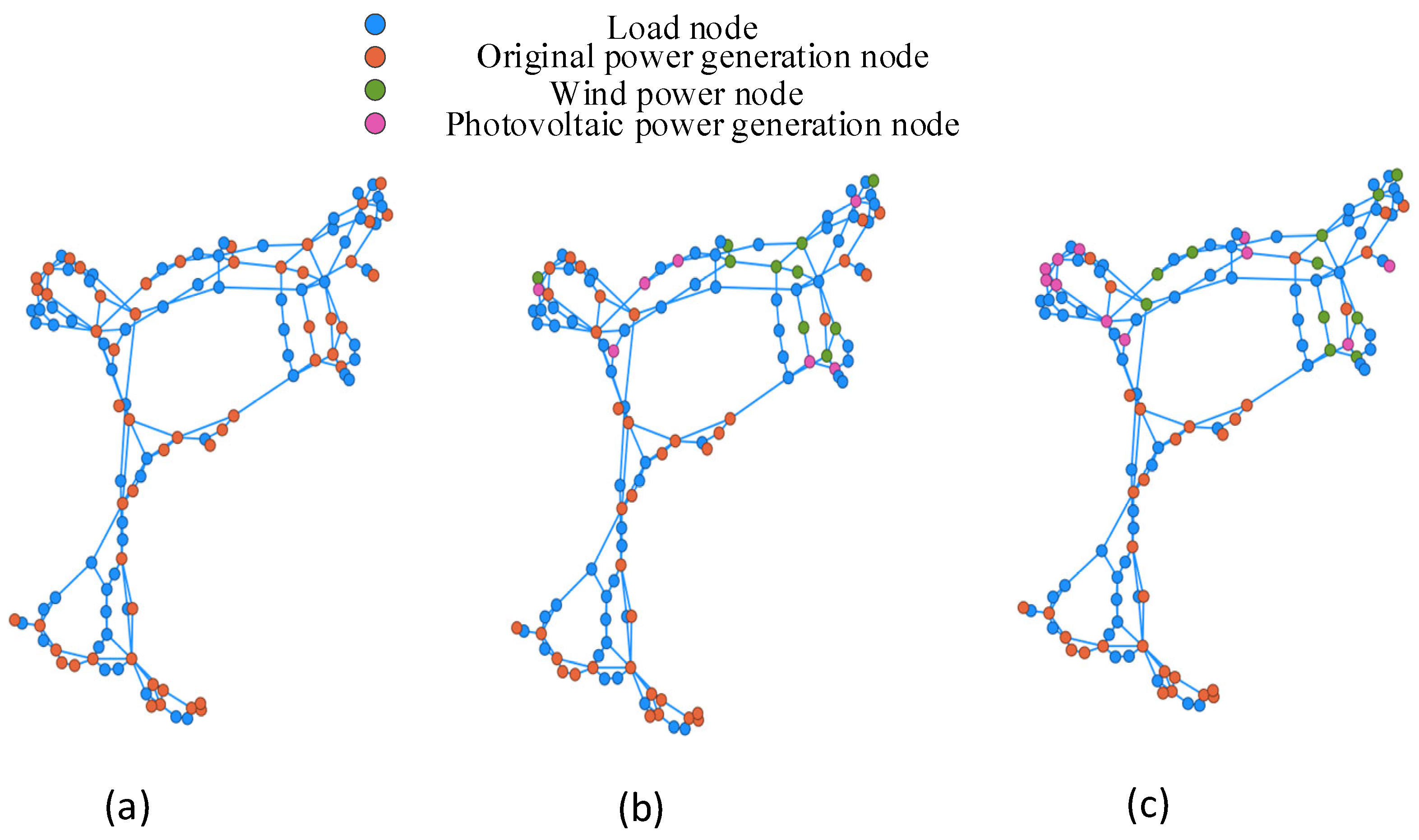
2.4. Graphical Modeling of Power Systems

In complex network theory, the power system is illustrated as a graph G = ( Φ , E , W ) , where Φ symbolizes the nodes. Specifically, Φ G is the node set of the synchronous generator, Φ W is the node set of the wind farm, and Φ P V is the node set of the photovoltaic plant. E is the set of edges, and W represents the weight of the edges. Here, nodes correspond to the buses of power plants, substations, and loads, and the edges are the transmission lines between two nodes.
To further reflect the electrical characteristics under different operational occasions, the weight of edges is described by the directed weighted adjacency matrix W, and its element w i j is defined as follows:
w i j = P i j , i , j E 0 , i , j E
where Pij represents the active power flowing from node i to node j. If power loss along transmission line i−j is neglected, its active power is defined as follows:
P i j = P from + P to / 2
where Pfrom and Pto represent the active power at the beginning and end of the transmission line, respectively.

2.5. Multi-Energy Complementary Characteristics

Power flow variates consistently due to the randomness and intermittency of wind power and PV generation. To study the impact of renewable energy on system resilience, the multi-energy complementary characteristics of different power sources need to be analyzed.
Power flow balance [25] is required at any time for power systems, which are as follows:
i Φ P V P i P V + j Φ W P j W + g Φ G P g G = b Φ ( P b D + P b L ) P i P V = P i P V , n + P i P V , x P j W = P j W , n + P j W , x P g G = P g G , n + P g G , x
where P b D is the nominal load at node b, and P b L is the load change at node b, which occurs when the system experiences disruptions or attacks. P i P V represents the power output of the ith PV node, while P i P V , n and P i P V , x are its output power and power change under normal operating conditions and under attack, respectively. P j W represents the output power of the jth wind power node, while P j W , n and P j W , x represent its output power and power change under normal operating conditions and under attack, respectively. P g G represents the power output of G node g, while P g G , n and P g G , x represent its output power and power change under normal operation conditions and under attack, respectively.
At the same time, the system constraints are as follows:
0 P i P V P max P V , 0 P i P V , x P i P V , n , r e d u 0 P j W P max W , 0 P j W , x P j W , n , r e d u P min G P g G P max G , 0 P g G , x ξ x P g G , n P max G P e P max e
where P max P V is the maximum power of the ith PV node, and P i P V , n , r e d u refers to the redundant power at the ith PV node i under normal operating conditions; P max W is the maximum power of wind power, and P j W , n , r e d u represents the redundant power at the jth wind power node under normal operating conditions; P min G and P max G are the lower and upper limits of the synchronous generator, respectively, and P g G , x is the power change under attack; P e and P max e denote active power and its upper limit along the eth transmission line, respectively; and ξ x is the maximum redundant ratio of the synchronous generator under normal operating conditions.
The complementary characteristics of different power sources are as follows: (1) When some renewable power sources are tripped off after an attack, the synchronous generators will adjust their output to try to balance power and narrow down the failure area. (2) If some synchronous generators are tripped off under attacks, other synchronous generators will change their power, while the renewable generations cannot increase their power due to external environmental constraints. Therefore, compared to traditional power systems, renewable energy power systems are more vulnerable to attacks due to the relatively small proportion of flexible power sources.
Meanwhile, due to the obvious “community structure” characteristics of power systems, the node connections between different communities are relatively sparse and much denser in the same community [23]. If there are node failures or power imbalances in one community, the power sources within the sub-community will adjust their power. In this paper, the system is partitioned into several zones using the integral islanding method in [26].

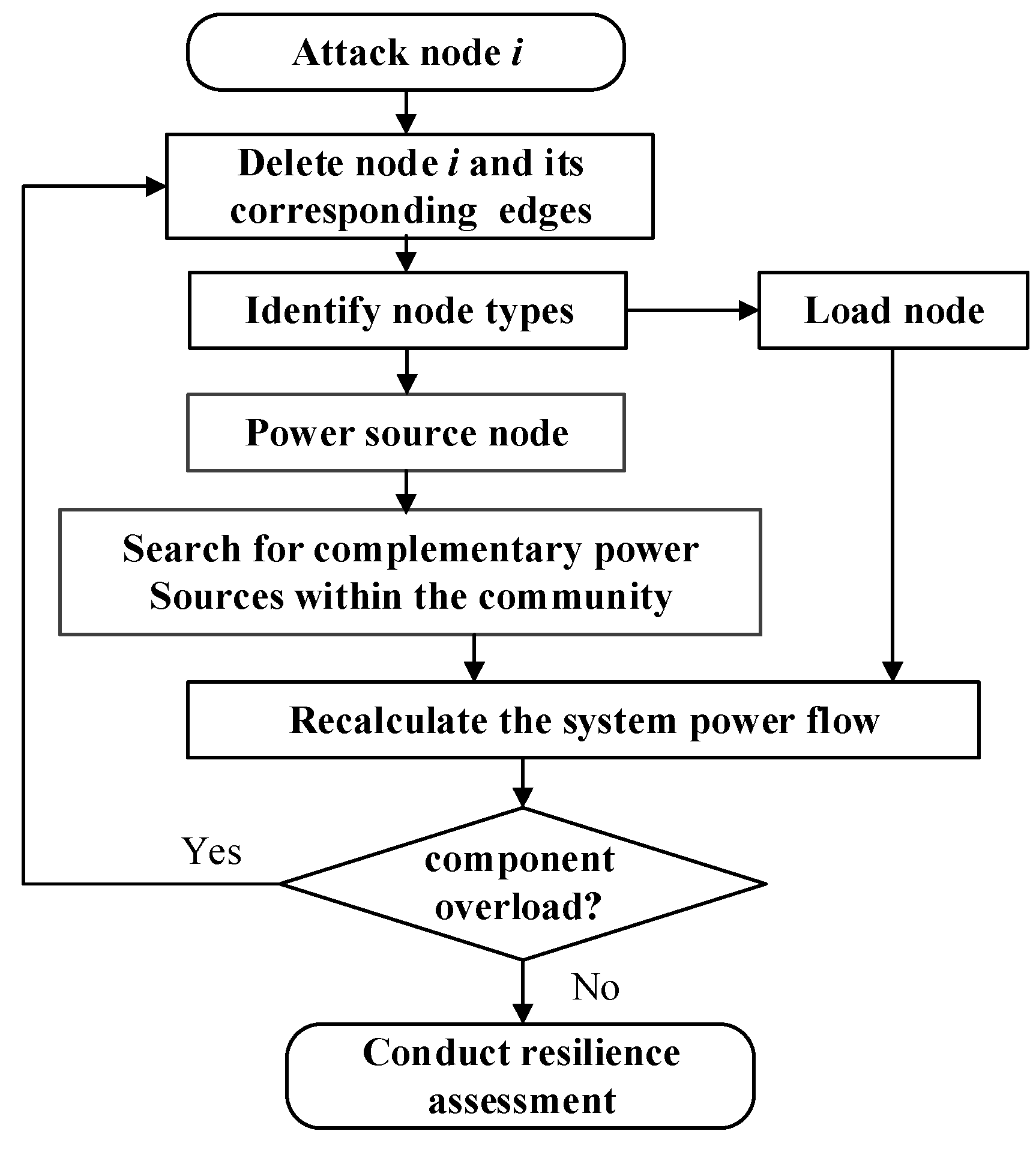
2.6. Cascading Failure Process

When node i in the system is attacked and unable to work properly, the power flow will transfer to other transmission lines, which may cause cascading failures within the system. Its simulation process is shown in Figure 4.
If node i is attacked and fails to work, node i and the edges connected to node i will be deleted based on graph theory. The power flow will transfer to other transmission lines. If the transferred power exceeds the maximum transmission capacity, the overloaded transmission lines will trip off.
To reflect the overload capacity of the transmission lines, a tolerance coefficient α was introduced as follows.
c i j = α P i j
Here, α represents the tolerance coefficient; cij denotes the capacity of the transmission line.
The cascading failure simulation process is as follows:
  • Step 1: Determine the attacked node i, and confirm the type of node.
  • Step 2:
    a.
    If node i is a load node, remove the node and its connected edges.
    b.
    If node i is a synchronous generator node, remove the node and its connected edges, and then, under the constraints of Formulas (5) and (6), search for the remaining synchronous generators at the same time to provide complementary power within their limits.
    c.
    If node i is a renewable energy node, remove the node and its connected edges. Under the constraints of Formulas (5) and (6), the synchronous generators will provide complementary generation within their limits.
  • Step 3: Recalculate the system’s power flow. If the fault causes a transmission line to exceed its capacity, cascading failures are triggered.
  • Step 4: The overloaded transmission line will be tripped off, and the power flow will be recalculated. This process will continue until there are no more overloaded components in the system.

3. Resilience Evaluation Indicators and Disaster Simulation

3.1. Resilience Evaluation Indicators

Based on the resilience trapezoid shown in Figure 2, the system state at time t is defined as St, which corresponds to EB,t (including EB,t,i and EB,t,o). Under different stages of St, the resilience of the system is evaluated with three indicators of largest cluster size [27], power flow entropy [28,29,30], and loss in power flow [27]. The largest cluster size (LCS) is used to describe the survival of system topology after attacks, and the loss in power (LP) is used to describe the power supply capacity of the system after disturbances. The LCS reflects the system performance from topology, and the LP is from the perspective of the system function after an attack. However, for power systems with high RES penetration, extreme events may lead to a substantial change in the original power flow distribution of power systems, and the time-varying nature of renewable power will exacerbate this effect. Moreover, the larger the integration scale of renewable energy, the more pronounced this impact becomes [29,30]. Therefore, the indicator of power flow entropy is also applied. The three indicators are defined as follows.
(1)
Largest Cluster Size (LCS)
The LCS is defined as the ratio of the maximum number of interconnected nodes to the total number of nodes in the network.
L C S ( S t ) = N l ( S t ) / N , 0 L C S 1
Here, N l is the number of nodes in the largest sub-network group l under St. L C S n is the LCS under normal conditions, and L C S d is the LCS after an attack.
The robustness metric B L C S is defined as follows:
B L C S ( S t ) = L C S n L C S d ( S t ) / L C S n
LCS is a critical index describing the structural performance of power systems. It reflects the ability of the system to maintain the maximum function based on the structure of the system. Moreover, it can simultaneously evaluate the rationality of the power grid construction and provide theoretical support for the further construction of a strong power grid.
(2)
Power Flow Entropy (PFE)
Entropy is a measure of the chaos and disorder within a system. The higher the entropy, the greater the level of disorder and volatility within the system. Power flow entropy quantitatively describes the imbalance of the power flow distribution. During extreme events, component failures lead to significant changes in the uniformity of the power flow distribution. The volatility of renewable energy generation and the constraints imposed by environmental factors will clearly exacerbate this impact. Therefore, the power flow entropy serves as a key indicator for measuring the resilience of power systems with high renewable energy penetration [29].
Let the load/capacity ratio of line i be μ i = actual power of the line/capacity limit of the line. Given a constant sequence U = [ U 1 , U 2 , , U M ] , lk represents the number of lines whose load/capacity ratio μ i ( U k , U k + 1 ] . The power flow entropy H E under St is defined as follows:
H E ( S t ) = m = 1 M 1 γ m ( S t ) ln γ m ( S t ) , γ m ( S t ) = l k ( S t ) / k = 1 M 1 l k ( S t )
HE can be normalized within the range of [0,1], represented as BHE.
B H E ( S t ) = [ H E ( S t ) H E min ( S t ) ] / [ H E max ( S t ) H E min ( S t ) ]
Power flow entropy quantifies the uniformity and variability of power distribution in the system. A lower entropy suggests a stable and balanced power flow, which is helpful in improving the system’s resilience to disturbances. A higher entropy indicates an unbalanced power flow, making the system more vulnerable to failures. The fluctuations in renewable energy generation power cause the distribution of lines across different load factor ranges to become highly uneven, resulting in an uneven power flow distribution in the grid. When facing extreme events, this uneven power flow distribution will be further exacerbated. This indicator is crucial for assessing the system’s stability and adaptability under different operating conditions.
(3)
Loss in Power Flow (LP)
The loss in power flow LP (0 < LP < 1) is the ratio of active power flow before and after an attack, which can measure the total power transmitted from the power source node to the load node; the formula is as follows:
B L P ( S t ) = 1 i = 1 N P d i ( S t ) / i = 1 N P n i = 1 E B , t , o ( S t )
where P n i and P d i are the active power of the load node i under normal operating conditions and after an attack, respectively.
The power flow loss reflects the decrease in energy transmission during attacks. A higher loss implies a significant disruption in power transfer, potentially leading to large-scale load loss. This indicator quantifies the extent of the system’s energy loss, offering insights into the system’s recovery capacity.

3.2. Attack Simulation

3.2.1. Key Nodes Based on Electrical Degree Centrality
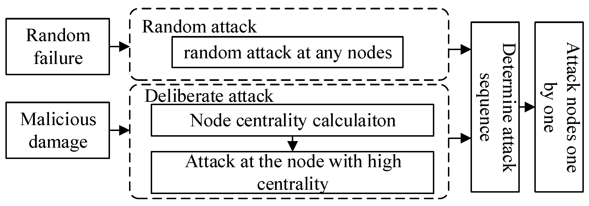
In complex network theory, the degree centrality of a node is defined as the number of edges directly connected to it. The higher the degree of centrality of a node, the more important it is in the power system. Considering the weighted directed nature of the system graphical model, the out-degree D i o u t is defined as the total power flowing out of node i, while the in-degree D i i n is defined as the total power flowing in node i.
D i in = 1 N 1 j = 1 N P i j , D i out = 1 N 1 j = 1 N P j i
The values of D i o u t and D i i n range within [0,1], where 0 represents an isolated node and 1 indicates that the node connects to all other nodes in the power grid.
The key nodes in the system can be identified by the highest in-degree centrality and out-degree centrality values first, and then the nodes with large loads.

3.2.2. Attack Mode

To evaluate the resilience of renewable energy power systems, both random attacks and deliberate attacks are considered in this paper. The random attack is used to represent random failure events, such as natural disasters or the sudden failure of a system component, while deliberate attacks are employed to represent extreme events like malicious actions or terrorist attacks. The attack modes are as follows:
  • Random Attack: A random attack may happen at any node of the system.
  • Deliberate Attack: Key nodes with high electrical degree centrality or high load will be attacked deliberately, and the system’s resilience is then evaluated based on the attack.
The simulation method for extreme events is depicted in Figure 5.

4. Case Analysis

4.1. Case Study

Using the IEEE 118-bus system as an example, Figure 6 shows the topology diagrams of the IEEE 118-bus system when the penetration of renewable energy is 0%, 20%, and 50%, respectively.
Using the real wind power and photovoltaic power of a Chinese provincial power grid as an example, the typical daily renewable energy profiles are shown in Figure 7.
The impact of penetration level and integration location of renewable energy on system resilience are analyzed under two typical attack modes: a random attack and a deliberate attack.

4.2. Resilience Curves
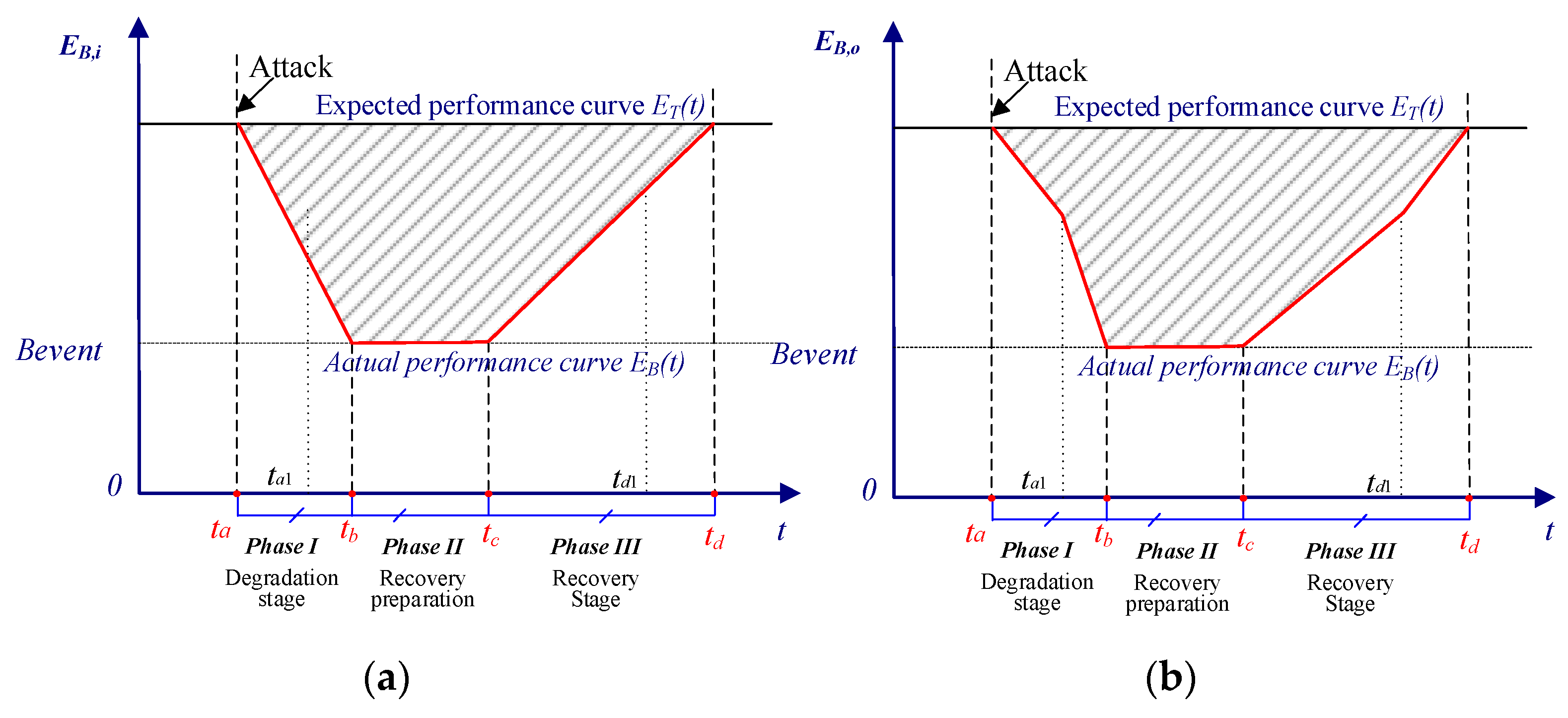
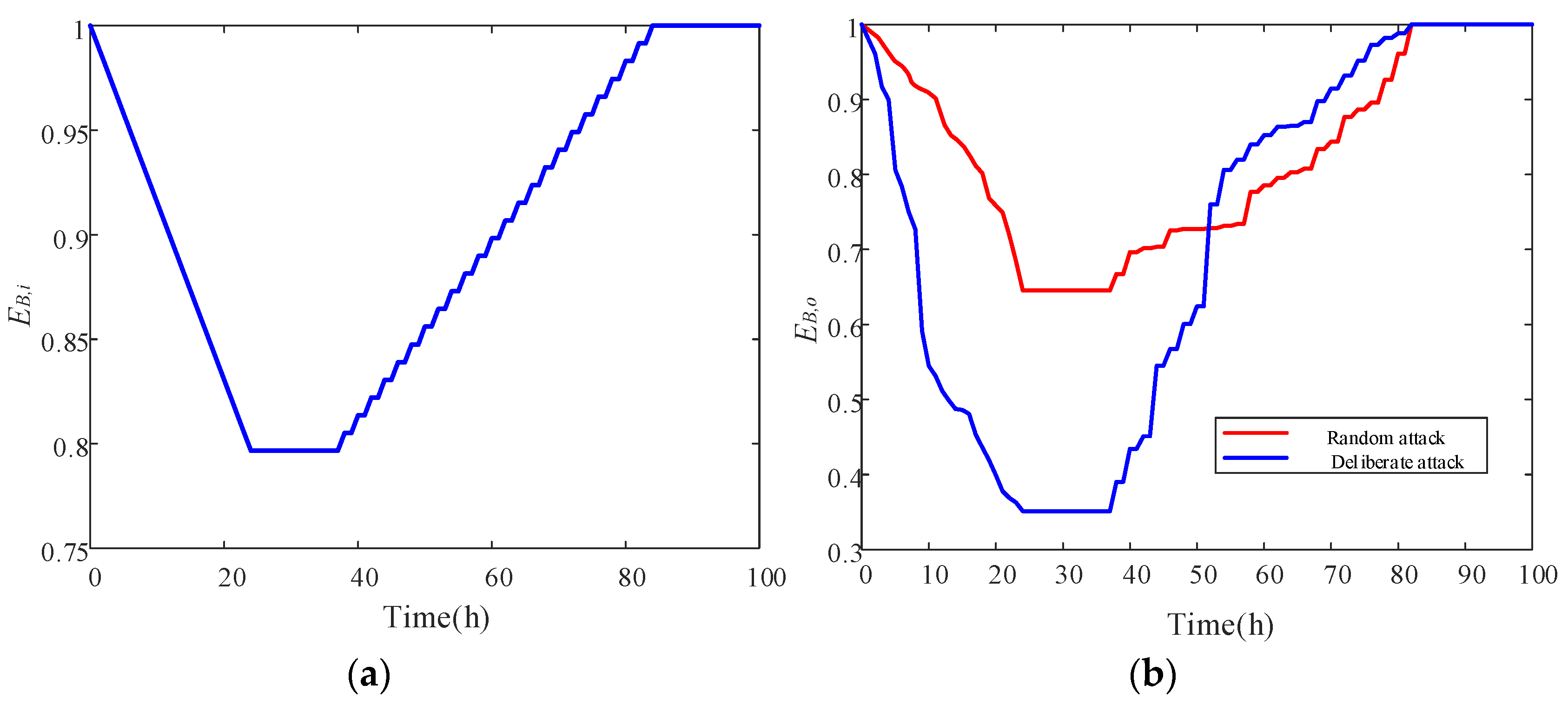
The parameters for the attack event are set as follows: the number of damaged components is one per hour, and the duration of the attack is 24 h. The preparation time for repairing each component is 0.5 h, and the repair time is 2 h. The recovery sequence of the system is based on node importance (Equation (13)), starting from the most critical node. Assuming a 50% penetration ratio of renewable energy generation in the IEEE 118-bus system, the attack occurs at 11:30 a.m. when the renewable energy power is at its maximum. Figure 8 shows the resilience curves of EB,i and EB,o under random and deliberate attack scenarios.
The following can be seen in Figure 8:
(1)
Resilience curves of EB,i and EB,o exhibit typical polygonal characteristics. In both scenarios, the resilience curves of EB,i and EB,o show three distinct phases: the degradation stage, recovery preparation stage, and recovery stage.
(2)
The functional resilience indicator EB,o is much lower than the infrastructure resilience indicator EB,i, indicating that the system’s degradation rate and recovery rate are different from different evaluation perspectives. Therefore, infrastructure indicators and functional indicators need to be considered simultaneously.
(3)
The infrastructure resilience EB,i is only influenced by the number of attacked nodes, resulting in identical curves under random attack and deliberate attack. The EB,o under deliberate attack is much lower than the one under random attack; this is because the most important node is selected to disrupt under deliberate attack. However, the recovery rate under deliberate attack is faster than the one under random attack, causing the two curves to cross during the recovery stage.

4.3. Impact of Attack Time

The attack ratio R ( 0 < R < 1 ) is defined as the proportion of nodes under attack relative to the total number of nodes. The value of R is different during different stages of the system; therefore, the average value under different stages is calculated.
R B = N a t t a c k N o s
where N a t t a c k is the number of attacked nodes. When the system reaches the collapse threshold, the R value is denoted as RB, where B represents LCS, HE, or LP.
Two attack times are selected: one is at 11:30 a.m. when the renewable energy outputs maximum power; the other is at 21:00 p.m. when the net load reaches the maximum. In [23], it is pointed out that when the system frequency drops to 48 Hz, the system reaches its maximum power deficiency; in this situation, the active power decreases by 36%. Therefore, this study considers system collapse at a power shortage of 36%.
(1)
Attack at maximum power of renewable energy (11:30 a.m.)
The resilience curves under a random attack and a deliberate attack at 11:30 a.m. are calculated, which are shown in Figure 9.
The following can be inferred from Figure 9:
(1)
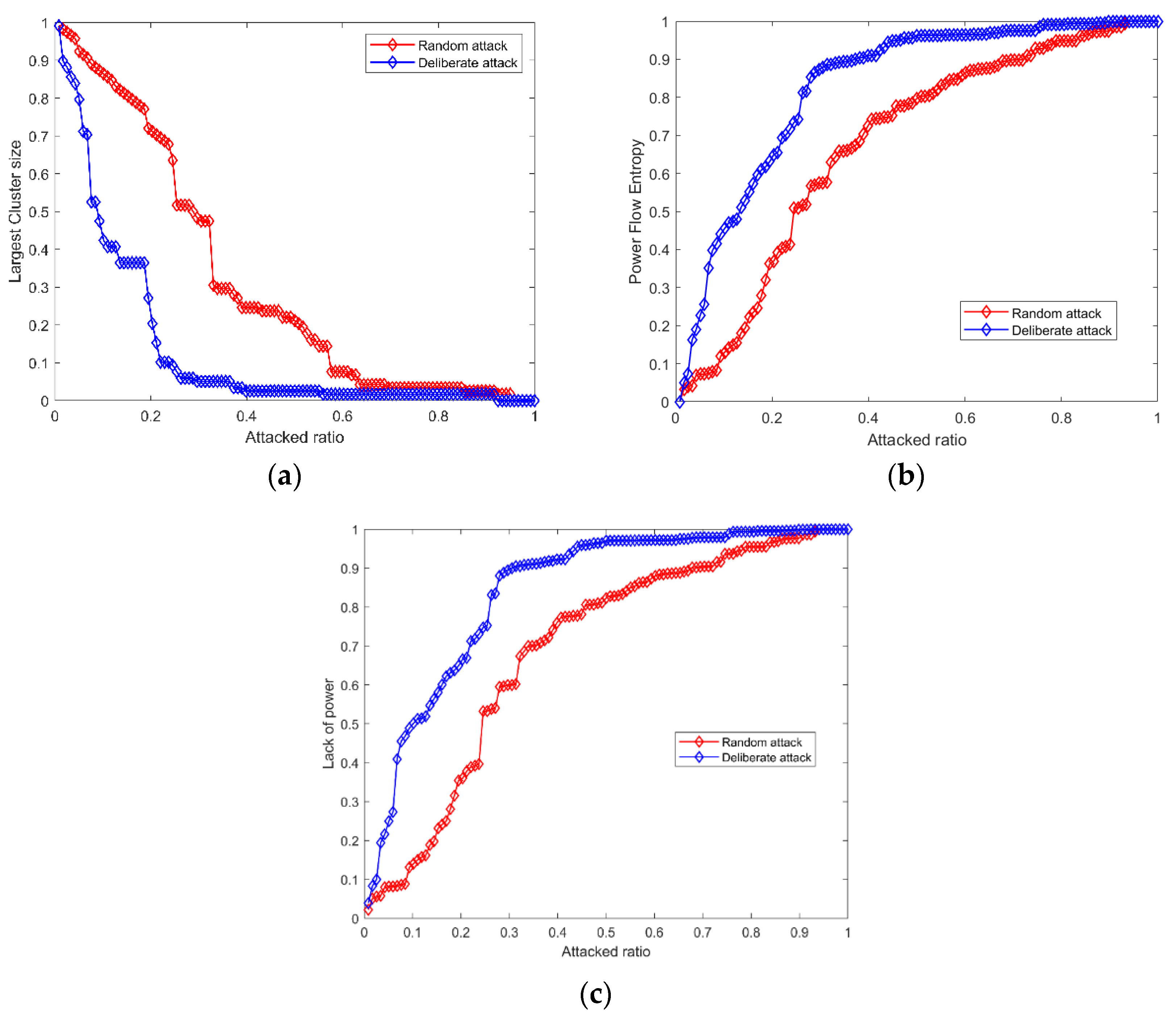
The LCS index is smaller under a deliberate attack than that under a random attack. Specifically, under a random attack, the LCS index drops significantly if the attack ratio is larger than 0.23, and the system will collapse if the attack ratio is larger than 0.57. Under a deliberate attack, the LCS index drops sharply when the attack ratio is larger than 0.05, and the system may crash when the attack ratio is larger than 0.24.
(2)
The PFE index is smaller under a deliberate attack than that under a random attack. Specifically, under a random attack, the PFE index drops at a high speed if the attack ratio is larger than 0.23; after that, the index will decrease continuously at a slow rate, and the system may collapse when the attack ratio is larger than 0.68. This is because, after a certain proportion of nodes are removed, the structure of the system changes, and may form a new sub-community. As the attack continues, the index will decrease sharply, resulting in system collapse. However, under a deliberate attack, the system will collapse if the attack ratio is larger than 0.37 owing to the continuous selective attack on important nodes.
(3)
The LP index is larger under a deliberate attack than that under a random attack. The system will collapse if the attack ratio is larger than 0.22 and 0.07, respectively, under a random attack and deliberate attack.
(2)
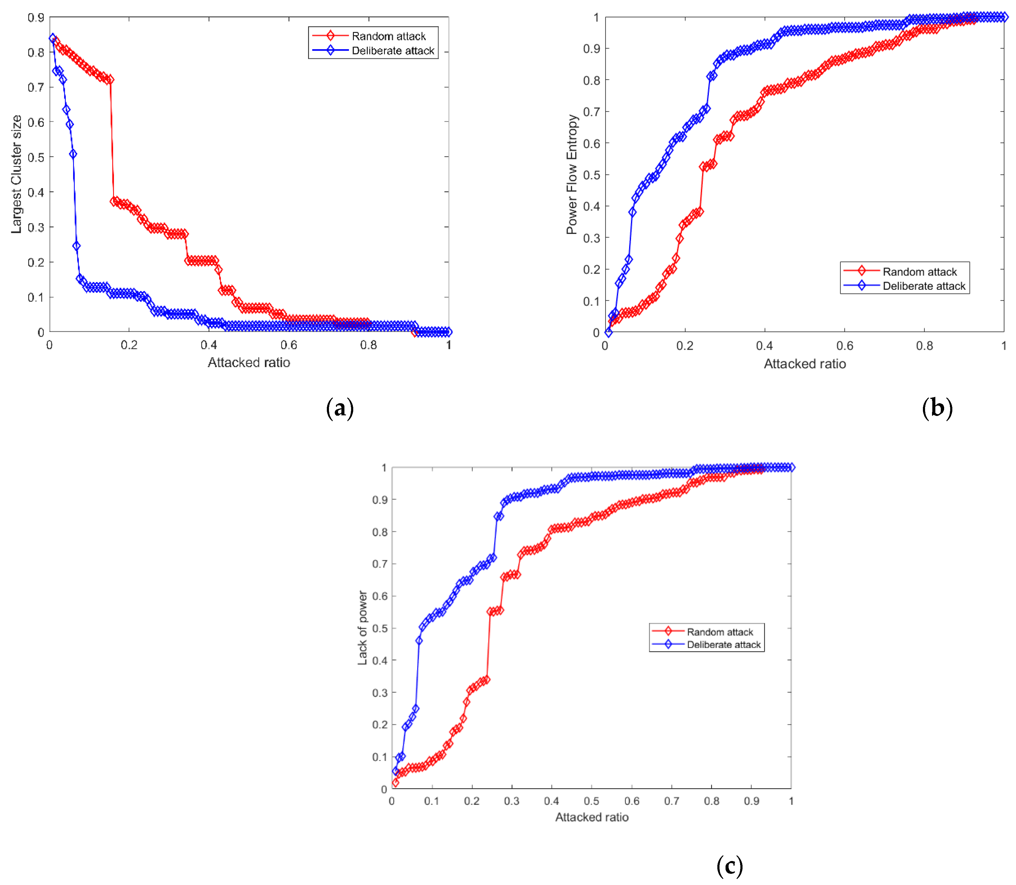
Attack at peak load (21:00 p.m.)
The following can be noted from Figure 10:
(1)
The initial value of BLCS is 0.84, which is affected by the proportion of renewable energy. Under a random attack, a sharp drop occurs when the attack ratio is larger than 0.15, and the system will completely crash when the attack ratio is larger than 0.45. In the case of a deliberate attack, the system starts to break down over a wide range from the beginning of the attack, and the system will lose its function when the attack ratio is larger than 0.23.
(2)
Under a random attack, the PFE index value drops obviously when the attack ratio is larger than 0.17, and the system will collapse when the attack ratio is larger than 0.66. However, under a deliberate attack, the survivability of the system reaches the limit when the attack ratio is equal to 0.37; the attack will lead to cascading failures, which will affect the function of the entire system.
(3)
The LP resilience curves are shown in Figure 10c. When faced with a random attack and a deliberate attack, the system will reach its operation limit when the attack ratio is equal to 0.24 and 0.06, respectively.
Table 1 summarizes the resilience index limit when the system collapses at two attack times.
From Table 1, it can be seen that system resilience is higher when the attack occurs at the maximum power of renewable energy, compared with the resilience results when the attack occurs at peak load. This is due to the complementary characteristics of different power sources. Under the same load level, the higher the supply of power sources, the greater the resilience of the system. Moreover, system resilience is poor under a deliberate attack, whereas it is relatively high when randomly selected nodes are attacked.

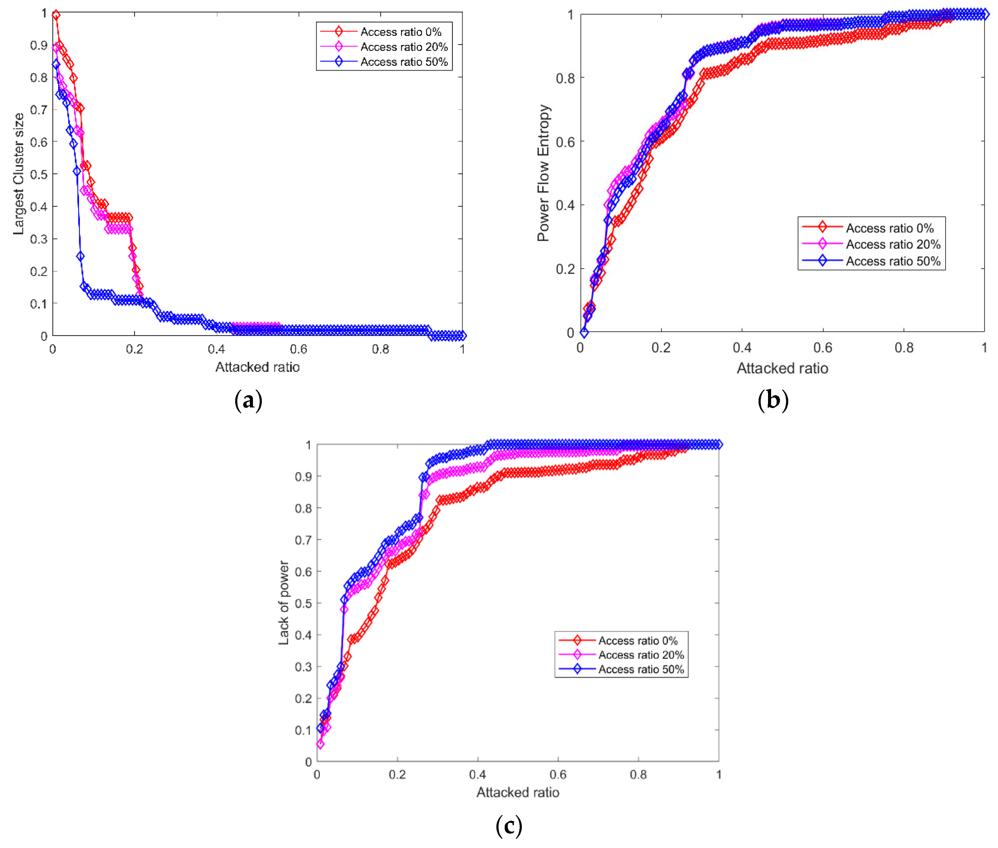
4.4. Different Penetration Levels of Renewable Energy

Considering an intentional attack on the system at the maximum net load as an example, the resilience indexes under different penetration levels of renewable energy (0%, 20%, and 50%) are shown in Figure 11.
The following can be observed from Figure 11:
(1)
The higher the penetration level of renewable energy, the smaller the RLCS and the worse the structural resilience of the system. RLCS values under the two scenarios of 0 and 20% renewable energy penetration are close, indicating that the structural resilience of the system is unaffected by the low penetration level of renewable energy.
(2)
The higher the penetration level of renewable energy, the smaller the RHE, and the worse the power flow balance of the system. RHE values under the two scenarios of 20% and 50% renewable energy penetration level are close; however, there is a large difference compared to the RHE under the scenario of no renewable energy integration, indicating that the power flow balance is more sensitive to renewable energy.
(3)
The higher the proportion of renewable energy, the higher the RLP and the higher the loss of load after the attack.

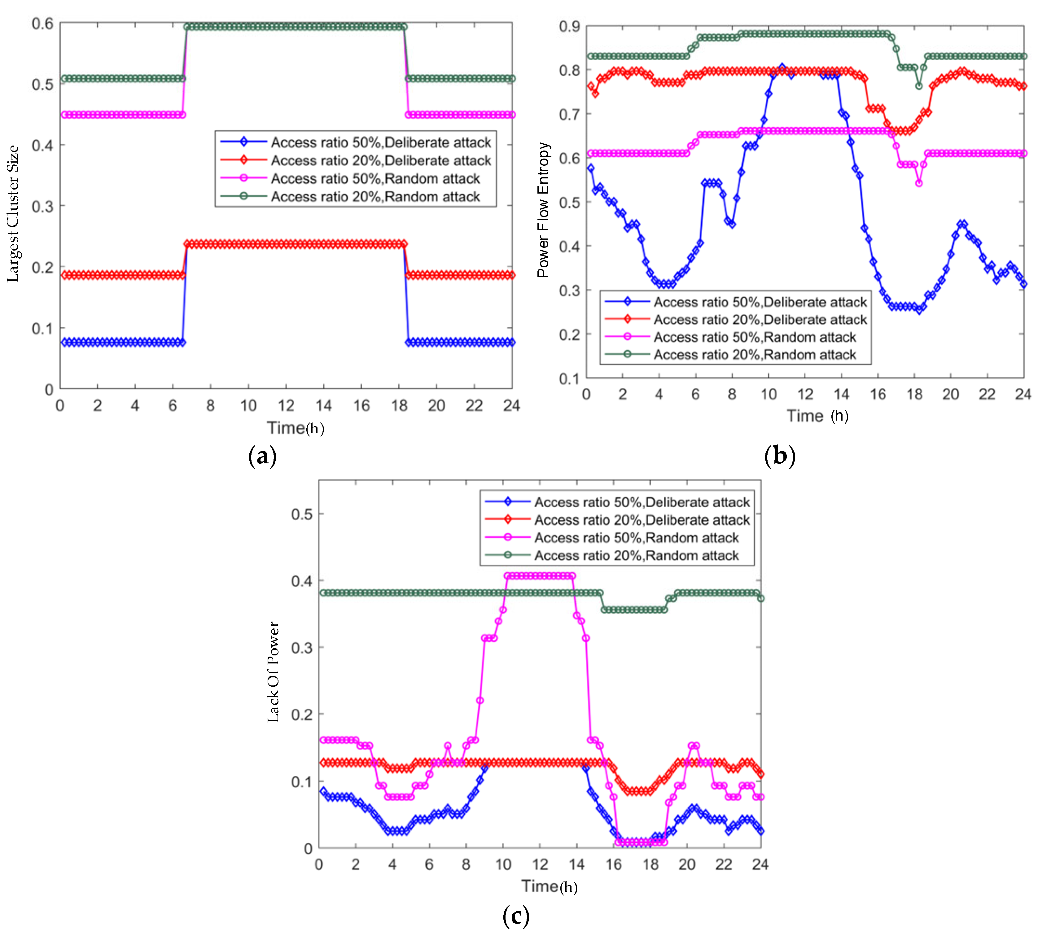
4.5. Resilience Evaluation Considering Power Fluctuation of Renewable Energy

In Figure 12, the system resilience is calculated every 15 min within one day, in which the impacts of power fluctuation of renewable energy can be studied. In Table 2, the resilience of the system is shown under two scenarios of 20% and 50% renewable energy penetration rate, respectively, and a random attack and a deliberate attack are simulated. The possible attack ratio when the system is close to collapse under different resilience indexes and its probability distribution are shown in Table 2.
The following can be inferred from Figure 12 and Table 2:
(1)
In the middle of the day, the resilience of the system reaches its peak when the PV power is sufficient, and the system resilience reaches its second-highest point when the wind power generation is sufficient at night. The system is more robust under a random attack than under a deliberate attack.
(2)
Compared to the resilience of the system when the renewable energy penetration level is 50%, system resilience is significantly higher when the penetration level is 20%. Therefore, renewable energy integration has a significant impact on system resilience. The higher the proportion of renewable energy, the lower the resilience of the system.
(3)
Regarding the structural index of LCS, there is an approximately 50% probability that the system will collapse at a certain attack ratio within a day, while there is an approximately 50% probability that the system will collapse at another attack ratio within a day. However, as for the operational indexes of PFE and LP, the probability of the system collapsing during an attack will be different. These phenomena show that the structural index and operational index should both be considered in the resilience evaluation of power systems.

4.6. Impact of Renewable Energy Distribution Characteristics

To study the impact of the distribution characteristics of renewable energy, the resilience of the system under the two distribution modes of centralized distribution and uniform distribution is analyzed. Considering a deliberate attack at 11:30 a.m. as an example, the penetration level of renewable energy is 50%, and the resilience of the system is illustrated in Figure 13. Since the maximum cluster size index is used to measure system structure, its value will not vary if the system structure remains unchanged. Figure 13 shows the indexes of BHE and BLP.
The following can be observed from Figure 13:
(1)
Regarding the resilience index of PFE, the system reaches its operational limit when the attack ratio is larger than 0.31 if renewable energy is unevenly distributed, while the operational limit will be reached when the attack ratio is 0.37 if renewable energy is uniformly distributed.
(2)
Regarding the index of BLP, the system will reach the operational limit when the attack ratio is 0.06 and 0.07, respectively, in the scenarios of centralized distribution and uniform distribution of renewable energy.
It is evident that the system resilience is affected by the distribution characteristics of renewable energy, and the resilience with a centralized distribution of renewable energy is lower than that with a uniform distribution.

5. Conclusions

A graphical model and a resilience evaluation farmwork are established based on the complex network theory to explore the resilience of power systems with a high share of renewable energy. Two typical attacks, which are random attacks and deliberate attacks, are simulated by an example of an IEEE 118-bus system. The system resilience is evaluated, and the impacts of the penetration level of renewable energy, the attack time, and the distribution characteristics of renewable energy are discussed.
The following conclusions can be drawn:
(1)
The system demonstrates lower resilience when it is subjected to a deliberate attack compared to a random attack. As the penetration level of renewable energy increases, the system’s resilience will decrease, highlighting the vulnerability of renewable energy power systems to targeted attacks.
(2)
The system resilience is higher when the attack is at the maximum power of renewable energy, compared to the one when the attack time is at peak load. Additionally, both renewable energy penetration level and its distribution characteristics significantly influence system resilience. As the renewable energy penetration increases continuously, the system resilience will decrease gradually. At the same time, system resilience is lower under a centralized renewable energy distribution than the one under a uniform distribution.
The proposed resilience assessment method will enhance the safe and stable operation of power systems. It helps identify vulnerabilities related to the power fluctuation of renewable energy, guiding operators and policy makers in designing strategies to mitigate these challenges. Ultimately, the work will increase the system’s hosting capacity for renewable energy, supporting a robust power system with a high share of renewable energy.
To further enhance the resilience of renewable energy power systems, future research will focus on developing advanced dispatching techniques and optimal recovery strategies, particularly for deliberate attack scenarios. Additionally, they will incorporate more diverse energy sources, increasing flexible power sources and loads to mitigate the vulnerabilities identified in this study. Future studies could also explore emerging technologies, such as energy storage systems and smart grid management, to further improve system robustness against extreme attacks.

Author Contributions

Conceptualization, F.H. and X.P.; methodology, D.Z.; validation, D.Z., X.P. and F.H.; formal analysis, X.S.; investigation, D.Z.; resources, X.P.; data curation, X.S.; writing—original draft preparation, D.Z.; writing—review and editing, D.Z., X.P. and F.H.; visualization, D.Z.; supervision, F.H.; project administration, X.S. All authors have read and agreed to the published version of the manuscript.

Funding

This work is supported by the National Natural Science Foundation of China under Grants 52477089 and 52407094.

Institutional Review Board Statement

Not applicable.

Informed Consent Statement

Not applicable.

Data Availability Statement

Data is contained within the article.

Conflicts of Interest

The authors declare no conflicts of interest.

References

  1. Gil, E.M.; McCalley, J.D. A U.S. energy system model for disruption analysis: Evaluating the effects of 2005 hurricanes. J. IEEE Trans. Power Syst. 2011, 26, 1040–1049. [Google Scholar] [CrossRef]
  2. Liang, G.; Weller, S.R.; Zhao, J.; Luo, F.; Dong, Z.Y. The 2015 Ukraine Blackout: Implications for False Data Injection Attacks. J. IEEE Trans. Power Syst. 2017, 32, 3317–3318. [Google Scholar] [CrossRef]
  3. Busby, J.W.; Baker, K.; Bazilian, M.D.; Gilbert, A.Q.; Grubert, E.; Rai, V.; Rhodes, J.D.; Shidore, S.; Smith, C.A.; Webber, M.E. Cascading risks: Understanding the 2021 winter blackout in Texas. J. Energy Res. Soc. Sci. 2021, 77, 102106. [Google Scholar] [CrossRef]
  4. Technical Report on the Events of 9 August 2019. Available online: https://www.nationalgrideso.com/document/152346/download (accessed on 6 September 2019).
  5. Appendices to the Technical Report on the Events of 9 August 2019. Available online: https://www.nationalgrideso.com/document/152351/download (accessed on 6 September 2019).
  6. Zhang, C.; Wang, Y.; Zheng, T.; Zhang, K. Complex network theory-based optimization for enhancing resilience of large-scale multi-energy System. J. Appl. Energy 2024, 370, 123593. [Google Scholar] [CrossRef]
  7. Tapia, T.; Lorca, A.; Olivares, D.; Negrete-Pincetic, M. A robust decision-support method based on optimization and simulation for wildfire resilience in highly renewable power systems. J. Eur. J. Oper. Res. 2021, 294, 723–733. [Google Scholar] [CrossRef]
  8. Yang, R.; Li, Y. Resilience assessment and improvement for electric power transmission systems against typhoon disasters: A data-model hybrid driven approach. J. Energy Rep. 2022, 8, 10923–10936. [Google Scholar] [CrossRef]
  9. Henry, D.; Ramirez-Marquez, J.E. Generic metrics and quantitative approaches for system resilience as a function of time. J. Reliab. Eng. Syst. Saf. 2012, 99, 114–122. [Google Scholar] [CrossRef]
  10. Yao, Y.; Liu, W.; Jain, R.; Chowdhury, B.; Wang, J.; Cox, R. Quantitative Metrics for Grid Resilience Evaluation and Optimization. J. IEEE Trans. Sustain. Energy 2023, 14, 1244–1258. [Google Scholar] [CrossRef]
  11. Panteli, M.; Mancarella, P.; Trakas, D.N.; Kyriakides, E.; Hatziargyriou, N.D. Metrics and Quantification of Operational and Infrastructure Resilience in Power Systems. J. IEEE Trans. Power Syst. 2017, 32, 4732–4742. [Google Scholar] [CrossRef]
  12. Espinoza, S.; Panteli, M.; Mancarella, P.; Rudnick, H. Multi-phase assessment and adaptation of power systems resilience to natural hazards. J. Electr. Power Syst. Res. 2016, 136, 352–361. [Google Scholar] [CrossRef]
  13. Zhang, H.; Ma, S.; Ding, T.; Lin, Y.; Shahidehpour, M. Multi-Stage Multi-Zone Defender-Attacker-Defender Model for Optimal Resilience Strategy with Distribution Line Hardening and Energy Storage System Deployment. J. IEEE Trans. Smart Grid 2020, 12, 1194–1205. [Google Scholar] [CrossRef]
  14. Jufri, F.H.; Widiputra, V.; Jung, J. State-of-the-art review on power grid resilience to extreme weather events: Definitions, frameworks, quantitative assessment methodologies, and enhancement strategies. J. Appl. Energy 2019, 239, 1049–1065. [Google Scholar] [CrossRef]
  15. Panteli, M.; Trakas, D.N.; Mancarella, P.; Hatziargyriou, N.D. Power Systems Resilience Assessment: Hardening and Smart Operational Enhancement Strategies. J. Proc. IEEE 2017, 105, 1202–1213. [Google Scholar] [CrossRef]
  16. Jasiūnas, J.; Lund, P.D.; Mikkola, J. Energy system resilienceA review. J. Renew. Sustain. Energy Rev. 2021, 150, 111476. [Google Scholar] [CrossRef]
  17. Ma, X.; Zhou, H.; Li, Z. On the resilience of modern power systems: A complex network perspective. J. Renew. Sustain. Energy Rev. 2021, 152, 111646. [Google Scholar] [CrossRef]
  18. Wang, S.; Zhang, J.; Duan, N. Multiple perspective vulnerability analysis of the power network. Physica A 2018, 492, 1581–1590. [Google Scholar] [CrossRef]
  19. Zhou, D.Y.; Hu, F.N.; Wang, S.L.; Chen, J. Power network robustness analysis based on electrical engineering and complex network theory. J. Phys. A 2021, 564, 1–11. [Google Scholar] [CrossRef]
  20. Guohua, Z.; Ce, W.; Jianhua, Z.; Jingyan, Y.; Yin, Z.; Manyin, D. Vulnerability assessment of bulk power grid based on complex network theory. J. IEEE Int. Conf. Electr. Util. Deregul. Restruct. Power Technol. 2008, 1554–1558. [Google Scholar] [CrossRef]
  21. Das, L.; Munikoti, S.; Natarajan, B.; Srinivasan, B. Measuring smart grid resilience: Methods, challenges and opportunities. J. Renew. Sustain. Energy Rev. 2020, 130, 109918. [Google Scholar] [CrossRef]
  22. Lin, Z.; Wen, F.; Xue, Y. A restorative self-healing algorithm for transmission systems based on complex network theory. J. IEEE Trans. Smart Grid 2017, 7, 2154–2162. [Google Scholar] [CrossRef]
  23. Lian, X.; Qian, T.; Li, Z.; Chen, X.; Tang, W. Resilience assessment for power system based on cascading failure graph under disturbances caused by extreme weather events. J. Int. J. Electr. Power Energy Syst. 2023, 145, 108616. [Google Scholar] [CrossRef]
  24. Zhou, D.; Pan, X.; Guo, J.; Sun, X.; Wang, C.; Zheng, J. Resilience quantification of offshore wind farm cluster under the joint influence of typhoon and its secondary disasters. J. Appl. Energy 2025, 383, 125323. [Google Scholar] [CrossRef]
  25. Koç, Y.; Warnier, M.; Kooij, R.E.; Brazier, F.M. An entropy-based metric to quantify the robustness of power grids against cascading failures. J. Saf. Sci. 2013, 59, 126–134. [Google Scholar] [CrossRef]
  26. Zhang, H.; Peng, M.; Palensky, P. Intentional islanding method based on community detection for distribution networks. J. IET Gener. Transm. Distrib. 2019, 13, 30–36. [Google Scholar] [CrossRef]
  27. Zhou, D.Y.; Hu, F.N.; Wang, S.L.; Chen, J. Robustness analysis of power system dynamic process and repair strategy. J. Electr. Power Syst. Res. 2021, 194, 107046. [Google Scholar] [CrossRef]
  28. Dan, Y.; Liu, W.; Zhu, Y.; Cai, W.; Wang, W.; Liang, C. Self-organized critical state identification of power grid with centralized integration of large-scale wind power. J. Electr. Power Autom. Equip. 2016, 36, 127–133. [Google Scholar]
  29. Liu, W.; Cai, W.; Yangqing, D.; Liang, C.; Wang, J.; Wang, N.; Ma, Y. The evolution of grid’s self-organized criticality state based on entropy theory under the circumstance of large scale wind power centralized grid. J. Power Syst. Technol. 2013, 37, 3392–3398. [Google Scholar]
  30. Bao, Z.J.; Cao, Y.J.; Wang, G.Z.; Ding, L.J. Analysis of cascading failure in electric grid based on power flow entropy. J. Phys. Lett. A 2009, 373, 3032–3040. [Google Scholar] [CrossRef]
Figure 1. Schematic diagram of the IEEE 30-bus power system with renewable energy.
Sustainability 17 02058 g001
Figure 2. Resilience process of a renewable energy power system with (a) component failure rate EB,t,i and (b) load failure rate EB,t,o.
Sustainability 17 02058 g002
Figure 3. Resilience evaluation framework.
Sustainability 17 02058 g003
Figure 4. Cascading failure simulation process.
Sustainability 17 02058 g004
Figure 5. Simulation method for extreme events.
Sustainability 17 02058 g005
Figure 6. System topology with penetration levels of (a) 0%, (b) 20%, and (c) 50%.
Sustainability 17 02058 g006
Figure 7. Typical renewable energy profiles.
Sustainability 17 02058 g007
Figure 8. Resilience curves: (a) EB,i and (b) EB,o.
Sustainability 17 02058 g008
Figure 9. Resilience indexes of the system when the attack time is 11:30 a.m.: (a) largest cluster size, (b) power flow entropy, and (c) loss in power flow.
Sustainability 17 02058 g009
Figure 10. Resilience of the system when the attack time is 21:00 p.m.: (a) largest cluster size, (b) power flow entropy, and (c) lack of power.
Sustainability 17 02058 g010
Figure 11. System resilience with different penetration levels of renewable energy (the system is with maximum net load and is attacked deliberately): (a) largest cluster size, (b) power flow entropy, and (c) lack of power.
Sustainability 17 02058 g011
Figure 12. System resilience with different penetration levels of renewable energy: (a) largest cluster size, (b) power flow entropy, and (c) lack of power.
Sustainability 17 02058 g012
Figure 13. Resilience of the system with different distribution characteristics of renewable energy: (a) power flow entropy and (b) lack of power.
Sustainability 17 02058 g013
Table 1. Comparison of resilience results at two attack times.
Indicators11:30 a.m.21:00 p.m.
Random AttackDeliberate AttackRandom AttackDeliberate Attack
RLCS0.570.240.450.23
RHE0.680.370.660.36
RLP0.220.070.240.06
Table 2. Comparison of simulation results for one day.
IndexRandom AttackDeliberate Attack
20%50%20%50%
Attack RatioProbability DistributionAttack RatioProbability DistributionAttack RatioProbability DistributionAttack RatioProbability Distribution
LCS0.190.510.450.510.190.510.080.51
0.240.490.590.490.240.490.240.49
PFE0.550.860.540.730.480.570.450.52
0.590.070.550.250.470.390.470.25
0.600.040.580.020.490.010.460.21
LP0.380.820.070.420.130.740.030.54
0.360.150.150.340.110.180.130.22
0.370.030.410.160.080.060.080.11
Disclaimer/Publisher’s Note: The statements, opinions and data contained in all publications are solely those of the individual author(s) and contributor(s) and not of MDPI and/or the editor(s). MDPI and/or the editor(s) disclaim responsibility for any injury to people or property resulting from any ideas, methods, instructions or products referred to in the content.

