Article

Effect of Topographic Condition of Drainage Channel on the Interaction Between Granular Flow and Slit Dams

Department of Civil Engineering, School of Engineering, Tibet University, Lhasa 850000, China
*
Author to whom correspondence should be addressed.
Sustainability 2025, 17(4), 1649; https://doi.org/10.3390/su17041649
Submission received: 6 December 2024 / Revised: 9 February 2025 / Accepted: 11 February 2025 / Published: 17 February 2025
(This article belongs to the Section Hazards and Sustainability)

Abstract

:
One of the most dangerous geological disaster risks in mountainous areas is granular flow. Slit dams, which might partially block the granular flow and let downstream flow at a slower speed, have been crucial in reducing the geohazards associated with granular flow. In this work, the discrete element method (DEM) was used to explore the effect of the topographic condition of drainage channels, including slope angle and cross-section types, on the interaction between granular flows and slit dams. The interactions dynamic process between the dry granular flows and slit dams with different drainage channel cross-section types has been investigated. And the simulation results demonstrate the significance of taking drainage channel cross-section types into account when designing barriers, particularly slit dams. The flow process, particularly in channels with V-shaped and trapezoidal sections, is characterized by a more rapid movement and larger final accumulation length, potentially resulting in increased impact force on the downstream slit dams. Moreover, the cross-section types and slope angles jointly influence the regulation function and impact force. The dry granular flow in the drainage channel with a V-shaped cross-section leads to a smaller normal impact force and retention efficiency. Taking into account the complexity of construction, retention efficiency, and impact force, it can be concluded that a trapezoid shape is the most appropriate option from an engineering perspective. This research may add to the understanding of the relationship between granular flow and slit dams and help the engineering design of slit dams with scientific evidence.

1. Introduction

Granular flows may move at speeds up to 10 m/s, have a lengthy runout distance, and are difficult to predict, making them one of the most frequent geological disasters in mountainous places [1,2,3,4,5]. Granular flows, as a result, pose a catastrophic danger to downstream communities and infrastructure. For example, on 7 August 2010, a devastating rainstorm-caused debris flow catastrophe in Zhouqu County, Gansu Province, China, killed 1765 people and destroyed over 5500 houses [6]. As a result, the scientific and technical communities are becoming more concerned with the development of effective methods to prevent granular flow disasters.
On the one hand, drainage channels are extensively utilized in the lower basin areas with the primary objective of facilitating the discharge of debris flows [7]. In the majority of instances, the debris flow drainage channels were designed with rectangular or trapezoid cross-sections. However, when the slope is gentler, granular flows tend to deposit due to low velocities and regulation functions of check dams. The issue of siltation leads to escalated maintenance expenses and heightened vulnerability for downstream communities in the event of future debris flows. On the other hand, several mitigation measures have been developed in recent years, such as closed check dams [8,9,10], flexible barriers [11,12], and slit dams [13,14,15], which are frequently erected in flow channels to capture granular flows. Because protective structures are meant to withstand the impact force of a moving mass, estimating the anticipated impact force is critical for designing these mitigation measures properly [16,17,18,19]. The design of impact-resistant buildings is dependent on a thorough understanding of the debris–barrier interaction; unfortunately, our understanding of this mechanism remains limited [8,12,20,21,22,23,24,25].
Numerous small-scale experimental research as well as numerical modeling have been conducted to study the effects of granular flow on slit dams [26,27,28,29,30]. They mainly focus on the material properties (such as particle size, particle size distribution including the coarse boulder, slurry including the fines, and even the water content, liquid viscosity) [26,31,32,33], flow dynamic properties (Froude number), and the structural configurations of slit dams (such as slit size, slit numbers, and the slit spacing) or slit-type barriers (baffles, slit dams, grid dam, comb dam, dual-slit structures, etc.) [13,34,35,36,37,38,39]. For instance, Choi et al. [40] paid early attention to the effect of baffle configuration on flow–structure interaction, including the baffle height, numbers, and spacing. Subsequently, the interaction process between the granular flows and structures, the regulation mechanism, and the impact models were further investigated. For example, Leonardi et al. [41] used a physical flume test and DEM modeling to investigate the granular flow impact load as a function of particle size, slit size, and channel inclination. According to the findings, the concentration of forces at the slit demands planning for loads that are 2–3 times those of the remainder of the slit dam. These studies, however, have ignored the effect of cross-sectional shape on the flow–slit dam interaction and impact force by using the idealized rectangular cross-section. At present, the restricted research is merely confined to the analysis of small-scale flume tests, and it is arduous to disclose its internal mechanism [42]. Because of its ability to capture particle movements and force chain networks at the microscale, the DEM was used to analyze the entire mobile and impact process of the granular flows, as well as the effect of the cross-section shape of the drainage channel on the interaction between the dry granular flow and slit dam [21].
The rest of this paper is organized as follows. First, Jiang and Towhata’s [43] laboratory flume tests were used as a reference to design a DEM model in this study. The model was then calibrated by comparing the time history curves of the granular flow progress and the normal impact load. The numerical results are used to analyze the dynamics of the flow–slit dam interaction. The effects of drainage channel cross-section shape on normal impact force are then quantitatively investigated, and the evolution of the force impacting the barrier is discussed. Furthermore, the mechanism of flow–slit dam interaction is investigated from the standpoint of energy evolution. Our findings may be useful for improving the design of slit dams in the field.

2. Numerical Simulation

2.1. DEM Theory

Because of its ability to capture particle movements and force chain networks at the microscale, DEM is a popular tool for dealing with granular flow problems [44]. Granular flows were modeled as an ensemble of rigid monodisperse spheres in this study, and the structure was modeled using wall elements with no deformation. The motions of particle i are governed by the following equations:
m i d v i d t g = j = 1 n 1 F i j n + F i j t
I i d ω i d t = j = 1 n 1 M i j
where m i is the particle mass, g is the gravity acceleration; v i is the translational velocities, ω i is angular velocities; I i is the moment of inertia; F i j n and F i j t are the normal and tangential contact forces between the particles or between the particle and the structure; M i j is the torque.
The particle contact force is calculated using the Hertz–Mindlin (no slip) model in this paper. This model has been widely used in dry granular flow research [45]. The normal contact force is denoted as follows:
F n = F n c + F n d = 4 3 E * R * δ n 3 2 2 5 6 β S n m * v n r e l
The tangential contact force is written as
F t = m i n μ s F n , F t c + F t d = m i n μ s F n , S t δ t 2 5 6 β S t m * v t r e l
where E * , R * , and m * are the equivalent Young’s Modulus, equivalent radius, and the equivalent mass; δ n and δ t are the normal and tangential overlaps; v n r e l and v t r e l are the corresponding components of the relative velocity; μ s is the coefficient of static friction; S n and S t are the normal and tangential stiffness and are given by Equations (5) and (6);
S n = 2 E * R * δ n
S t = 8 G * R * δ n
where G * is the equivalent Shear modulus. β is the damping coefficient, given by
β = ln e l n 2 e + π 2
where e is the restitution coefficient. The ratio of the velocity components along the normal plane of contact after and before the collision is defined. According to previous research and experience, it is usually 0.6.

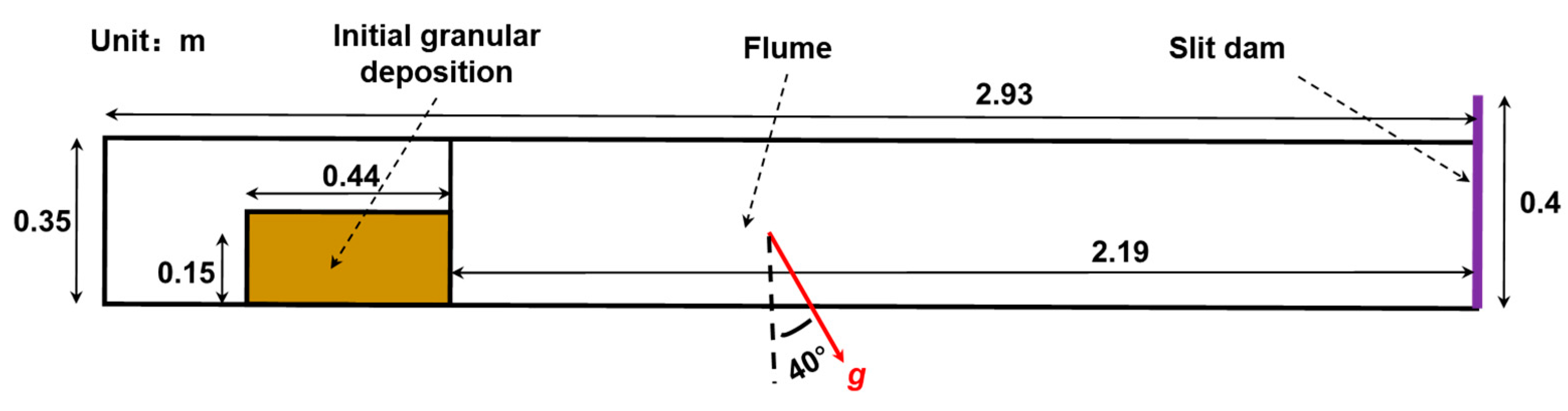
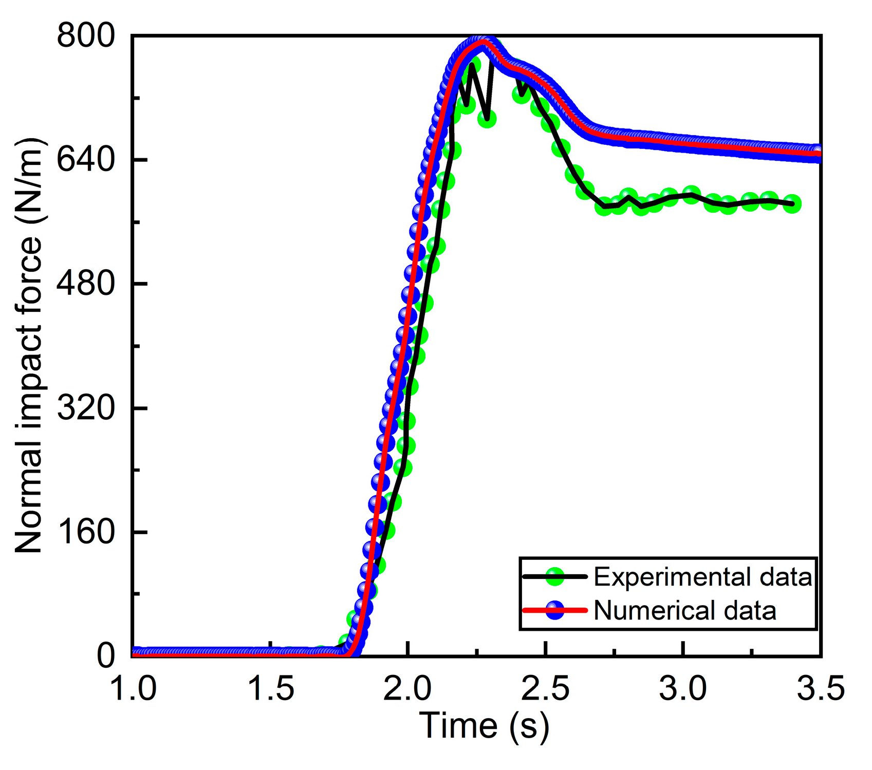
2.2. Model Setup and Validation

Jiang and Towhata’s [43] small-scale flume tests were used as a benchmark to confirm that the input material property parameters and contact parameters accurately simulate the flow–slit dam interaction and the entire description is presented in Figure 1. At the flume’s end, a rigid barrier measuring 0.40 m × 0.30 m in size was built. With a total of 20,409 particles that were 10 mm in diameter, an initial deposition that measured 0.15 m by 0.44 m by 0.30 m and had a unit weight of 13.5 kN/m3 under gravity was produced. The DEM’s material properties and contact parameters are described in Table 1 and Table 2. After all particles had been placed, the dam break was simulated by rapidly turning the trigger gate. The granular flow then slid down the flume under gravity and collided with the rigid barrier, and eventually, the granular flows were stopped before the rigid barriers, forming the dead zone. During the interaction between granular flows and rigid barriers, the normal impact forces of granular flows on the rigid barrier were recorded in real-time. The DEM model was calibrated by comparing the time history curves of the granular flow progress and normal impact force obtained by the flume test and DEM simulation, respectively. The granular flow morphology is shown in Figure 2 to consistently match the results of the flume test. Figure 3 shows the normal impact force’s temporal evolution. As can be seen, the numerical data agree with the experimental data, especially with regard to the peak characteristics of the normal impact force, with the exception of the residual forces. Although the residual forces are marginally larger in comparison with the results of the flume tests, the disparity is acceptable since the parametric analysis in this study did not concentrate on the residual impact force. Especially in practical engineering, because the peak dynamic impact force is much greater than the residual force (which can generally be regarded as static earth pressure), the peak impact force is typically taken into account. Thus, the higher agreement in flow progress and impact force between simulation and experiment shows that the DEM model is capable of accurately describing the flow–structure interaction.

2.3. Numerical Simulation Plans
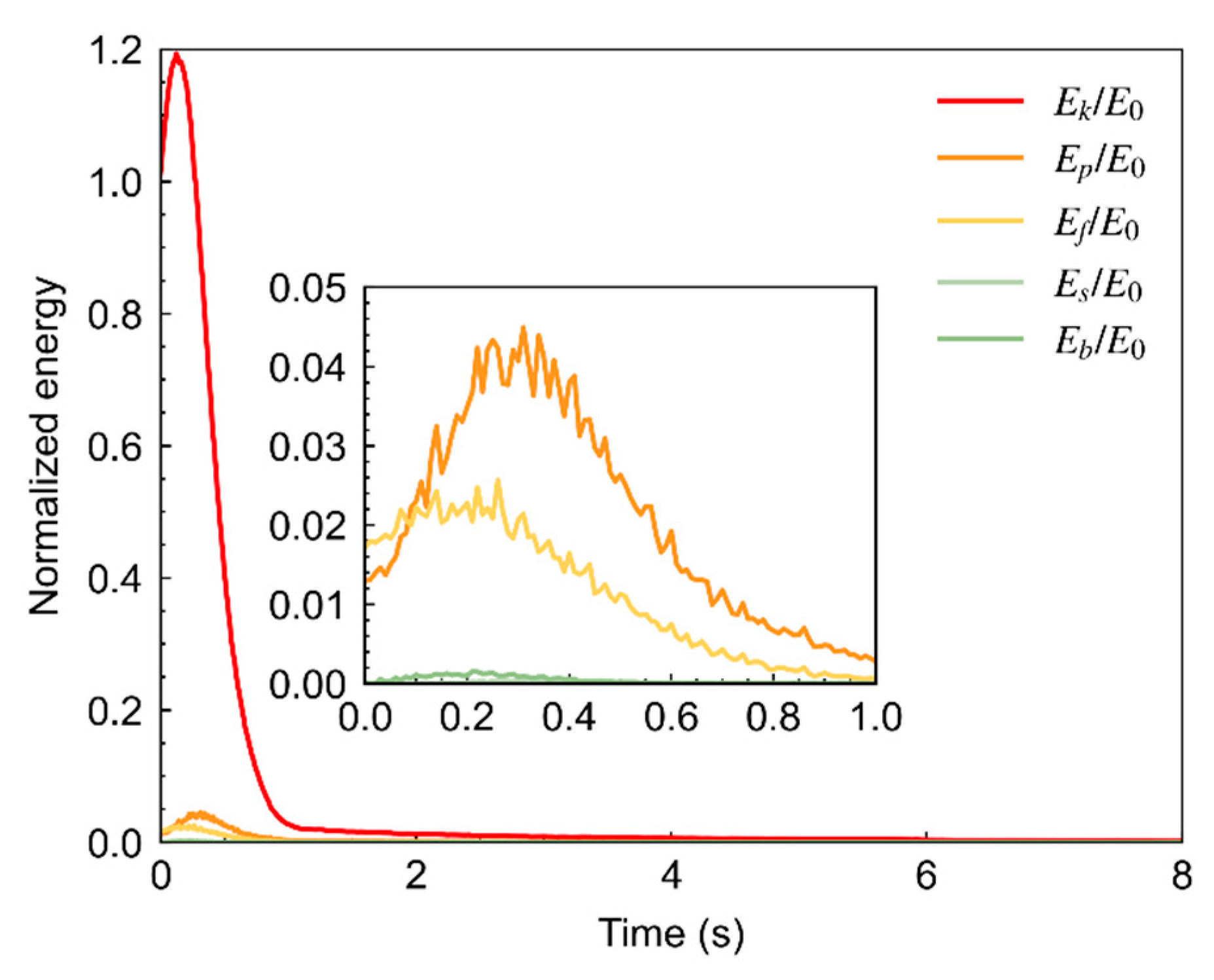
At the flume’s bottom end, a rigid slit dam inclined at an angle θ to the horizontal plane is installed. The slit measured 60 mm in width. To avoid overtopping, the slit dam was the same height as the closed barrier. The slope angle β varied from 10 ° to 50 ° , and the cross-section shape of the granular flow drainage channel includes three types: (i) V-shaped cross-section, (ii) trapezoid cross-section, and (iii) rectangular cross-section, which are shown in Figure 4. The area of all three cross-sections was kept constant at 0.105   m 2 . The simulation plan in this study is summarized in Table 3. The monitoring sections I are placed in front of the slit dam to record the flow kinematics. To ensure that no airborne particles are omitted, the monitoring sections span the entire width (0.3 m) of the flume as well as the entire height (0.40 m) of the sidewalls. The monitoring sections’ thickness is also set to 50 mm, which is 5.0 times the particle sizes used in the simulation (10 mm).

3. Results

This section may be divided by subheadings. It should provide a concise and precise description of the experimental results, their interpretation, as well as the experimental conclusions that can be drawn.

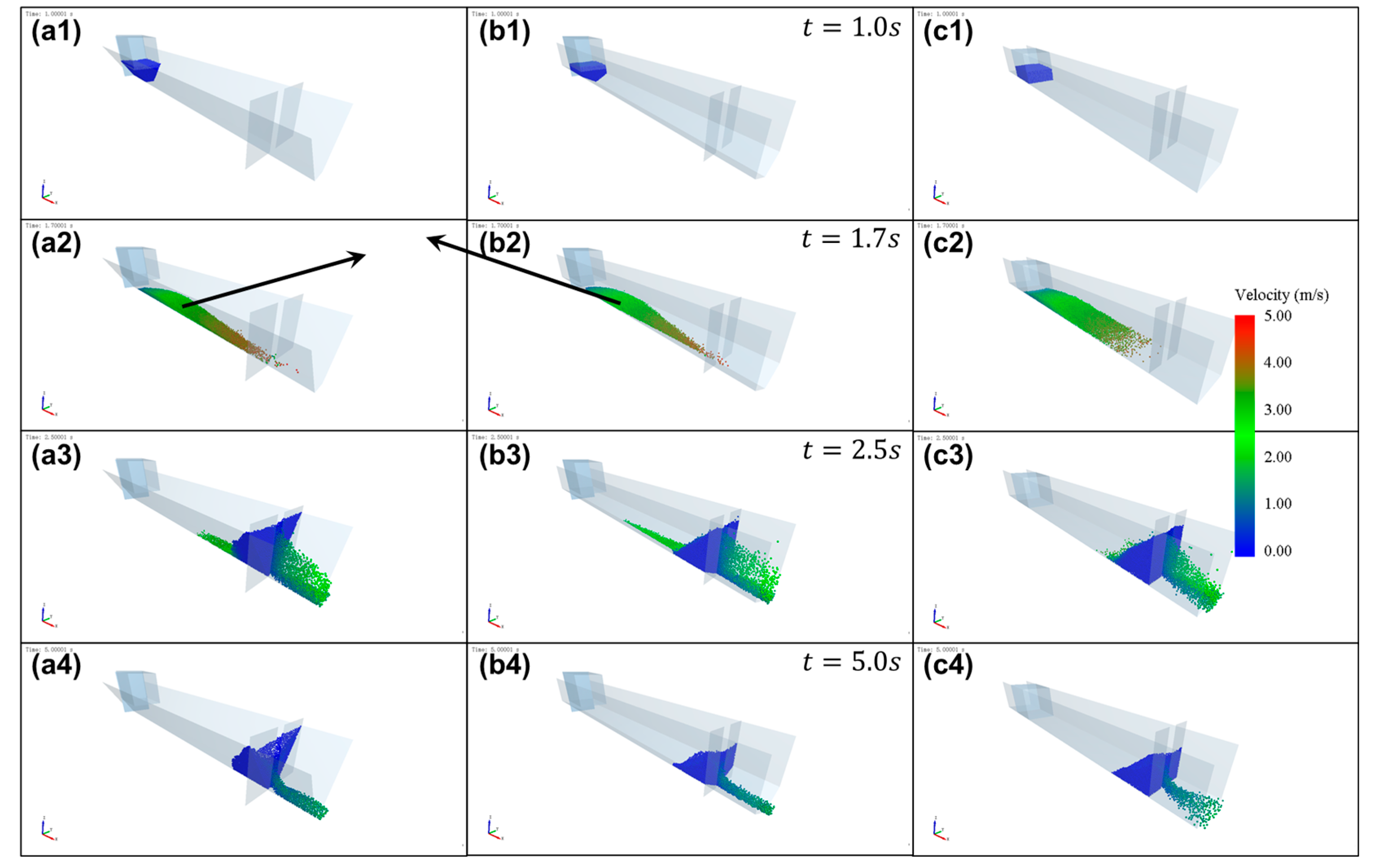
3.1. Flow–Slit Dam Interaction

The general characteristics of dry granular flow impacting on a rigid slit dam of β = 40 ° are illustrated in this section. Figure 5 depicts the snapshots of granular flows through slit dams for various drainage channel cross-section shapes. It can be observed that for the trapezoid cross-section and V-shaped cross-section, the granular flows reached the rigid barrier with a thicker front (Figure 5(a2,b2)) than the rectangular cross-section because of the narrower bottom width of the flume (Figure 5(c2)). The granular flow then impacted the slit dam, and the majority of the granular material was trapped in front of the slit dam on both sides, forming a dead zone, while a portion of the granular material flowed through the aperture (Figure 5(a3,b3,c3)). When the succeeding flow glided over the surface of the dead zone, this accumulated process continued until the dead zone reached its maximum height. During this process, the dead zone continues to develop, and the interaction between the subsequent flow and the dead zone contributes to deceleration. Conversely, the dead zone further constricts the cross-sectional area of the channel, resulting in increased granular flow velocity through the mouth. Following that, a portion of the trapped granular matter progressively flowed out the mouth, lowering the height of the dead zone and eventually forming a ramp-like dead zone.
Figure 6 shows the final deposition morphology of the dead zones for different cross-section shapes of β = 40 ° . Here, L D is the final accumulation length of the particles’ dead zone, and H D represents the final pile-up height of the particles’ dead zone behind the slit dam. As can be observed from the figures, although all of the final deposition morphology of the dead zones for different cross-section shapes of drainage channels exhibit a ramp-like form, the shape of the cross-section has a remarkable effect on the ultimate morphology of dead zones. The final pile-up height of the trapezoid cross-section (Figure 6(b1,b2)) is much larger than the V-shaped and rectangular cross-section. However, the rectangular cross-section results in a larger final accumulation length.
To further quantify the final deposition morphology of the dead zones, we defined two non-dimensional parameters: the normalized final accumulation length L D * = L D / L F , and the normalized final pile-up height H D * = H D / H F , where L F and H F are the length and width of the flume, respectively. The normalized deposition morphology parameters are displayed in Figure 7. It can be found that, with the increase of the angle of slope, the normalized final accumulation length L D * sharply decreases, whereas the normalized final accumulation height H D * gradually increases. For L D * , as can be seen in Figure 7a, when the slope is gentle, there exists a certain disparity in the L D * values among various cross-section types; however, as the slope becomes steeper, this gap diminishes to almost negligible levels. This indicates that L D * is primarily influenced by the angle of the slope. As for H D * , it can be found that there are significant disparities in H D * among different cross-section types across all angles. This indicates that the cross-section types remarkably influence the final accumulation height. The trapezoid cross-section type is more prone to yielding a larger pile-up height.

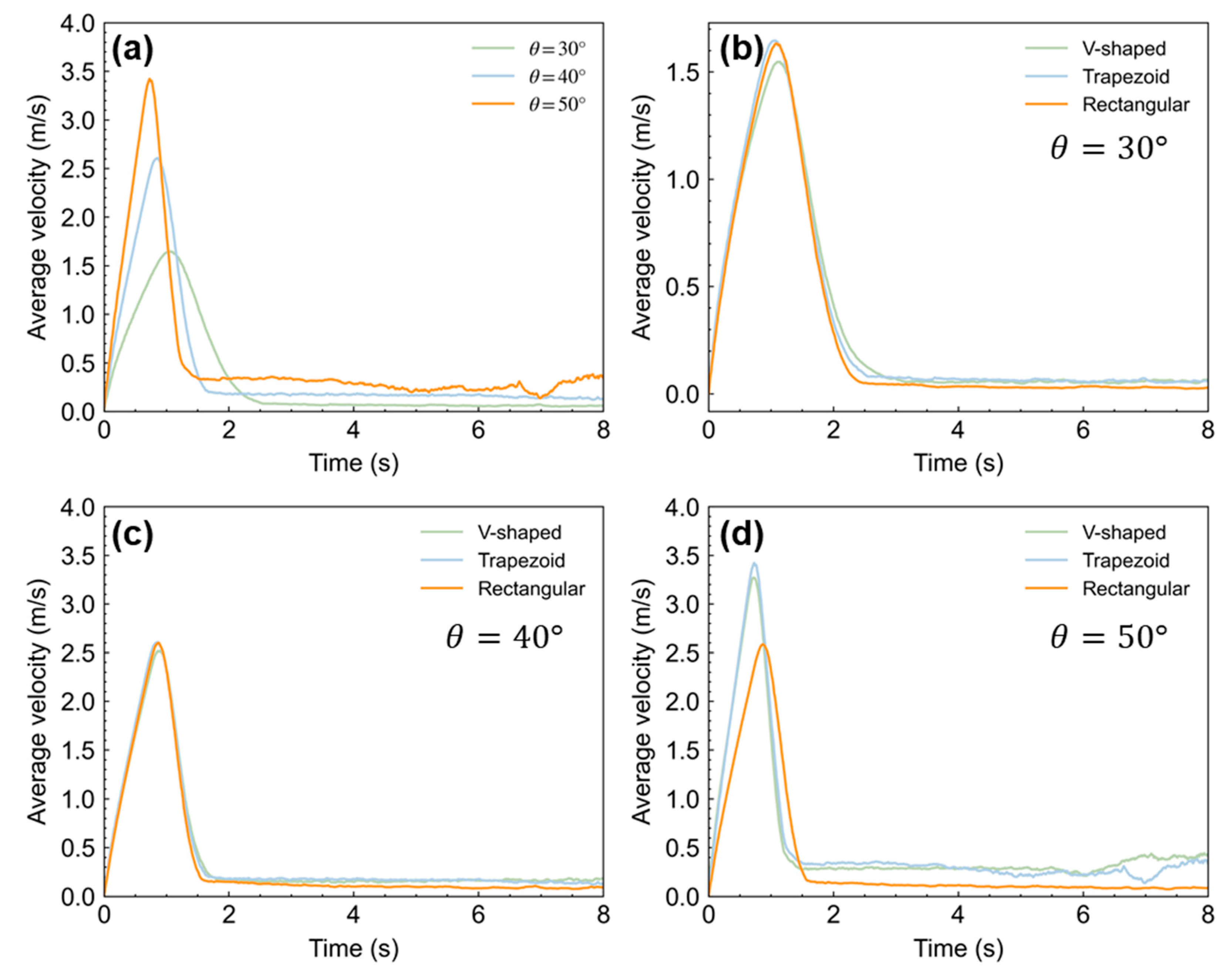
3.2. Average Velocity Evolution

Figure 8 shows the evolution of the average velocity of granular flows with time. The moment when the granular flows initially contact the slit dam is defined as t = 0 s. Based on the data presented in Figure 8a, it is evident that the trapezoid cross-section type exhibits a slight advancement in the time to reach peak velocity with an increase in slope angle. Furthermore, there is a corresponding increase in peak velocity as the slope angle increases, reaching 1.65 m/s at 30°, 2.59 m/s at 40°, and 3.42 m/s at 50°. Upon contact with the slit dam, the front of the granular flow experiences a rapid decrease in velocity; however, due to the break of granular arches, granular materials within the dead zone continue to pass through the slit dam and flow downstream, resulting in a sustained non-zero average velocity over an extended period of time.
As for the effect of cross-section types, it can be observed that when the slope angles are θ = 30 ° and 40 ° , the average velocity exhibited minimal difference. However, when the slope angle is θ = 50 ° , indicating a steeper slope, the average velocity of the V-shaped and trapezoid section type significantly exceeds that of the rectangular section. The reasons might be that the dynamic characteristics, such as average velocity, are collectively influenced by cross-section type and slope angles. When the channel is more gentle, the friction between granular flows and flume, such as flume base and flume sides, exerts significant control in the motion. However, when the channel is steeper ( θ = 50 ° in this study), the granular flows surpass flume friction, and the type of the channel cross-section significantly influences this process. The flow process, particularly in channels with V-shaped and trapezoidal sections, is characterized by a more rapid movement, potentially resulting in increased impact force on the downstream slit dams.

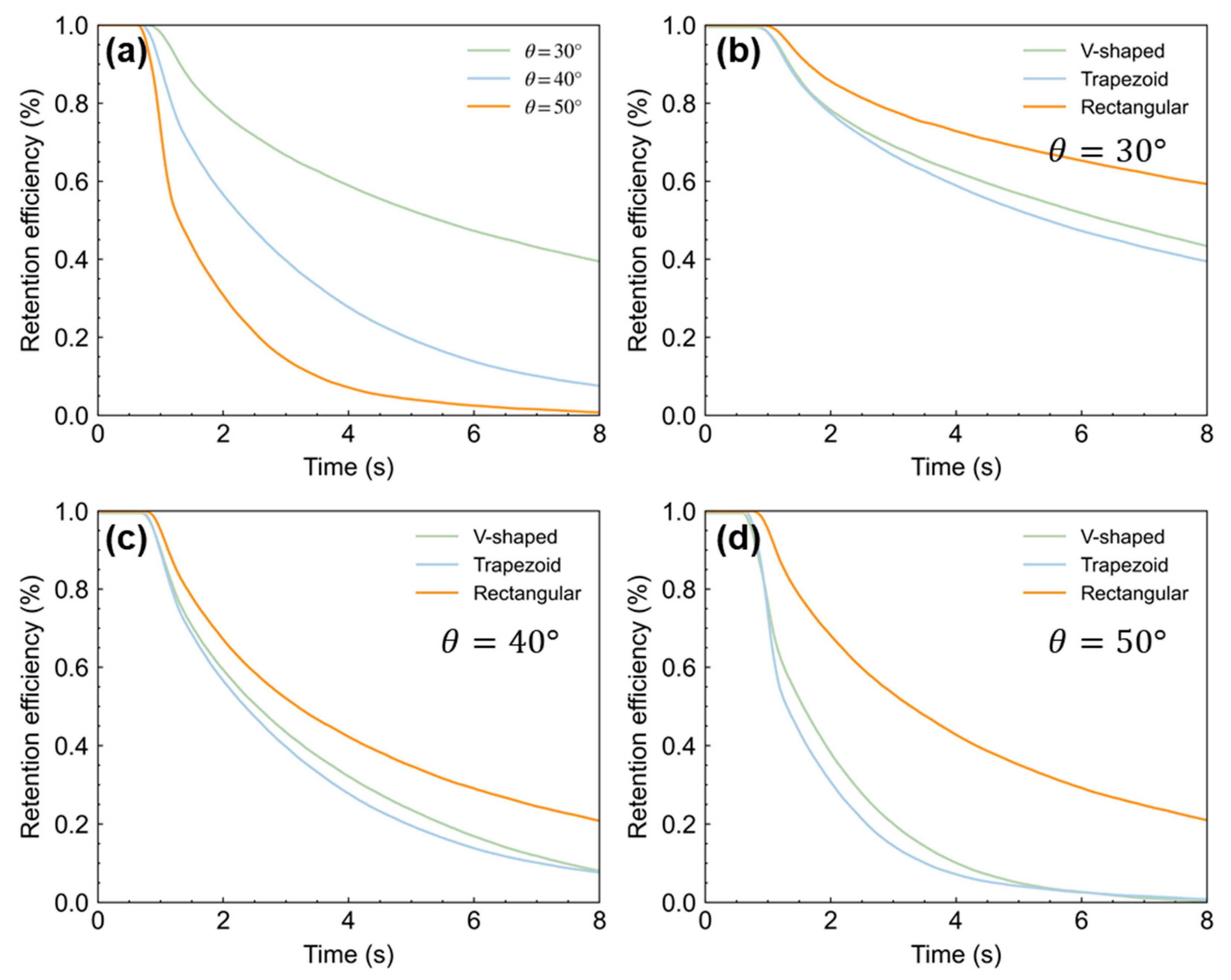
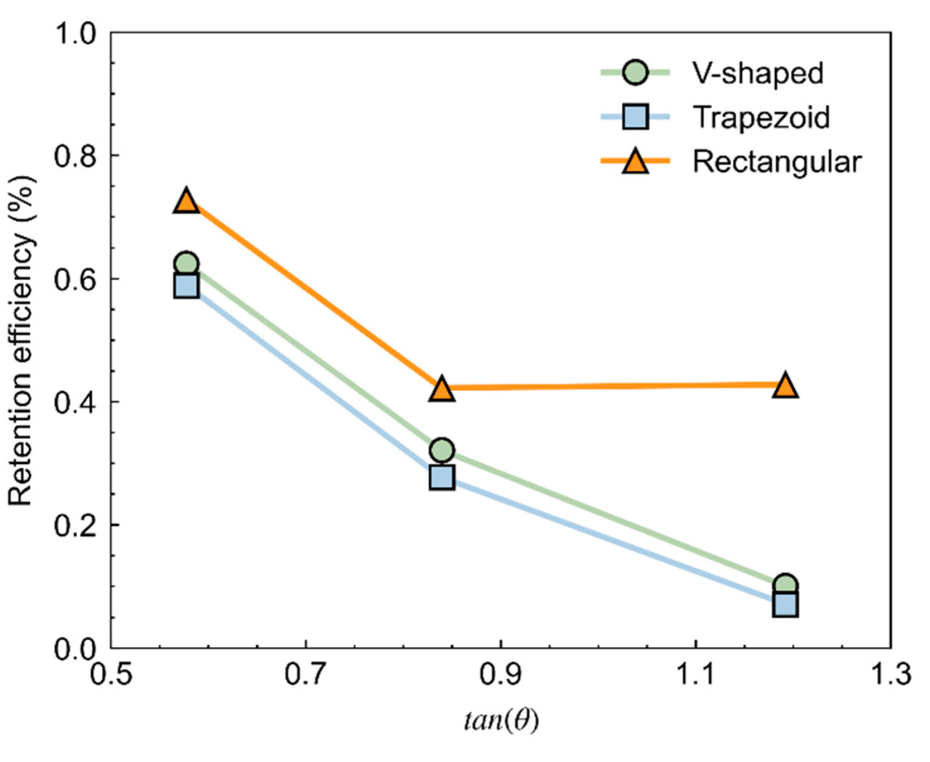
3.3. Retention Efficiency
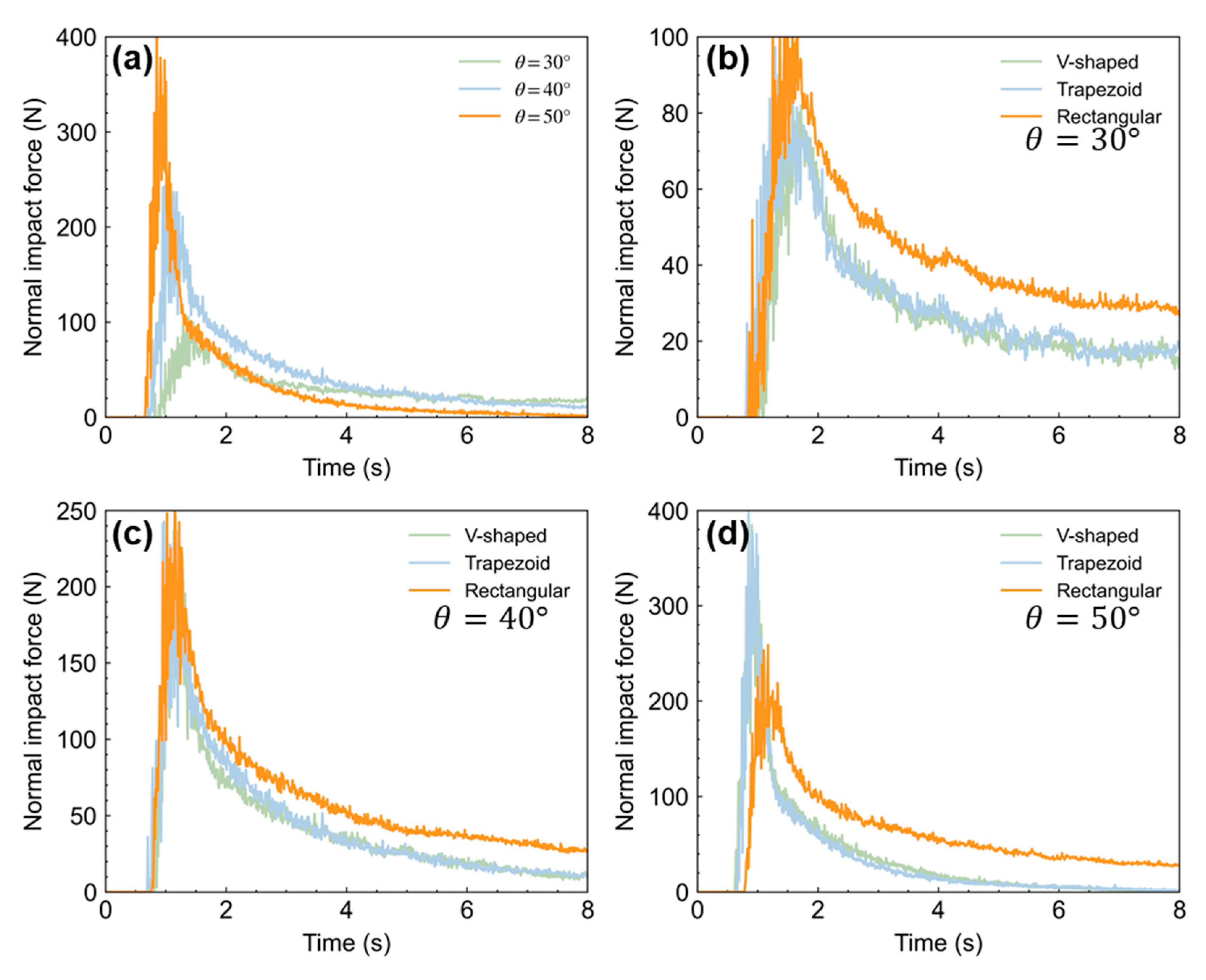
The most important functions of slit dams are to partly trap the solid matter. Therefore, this study performed a parametric analysis of the granular retention efficiency. The retention efficiency in this study is quantified as the proportion of particles remaining behind the slit dam relative to the initial quantity of particles. The retention efficiency under different slope angles and cross-section types is shown in Figure 9. As depicted in Figure 9a, it is evident that the retention efficiency decreases significantly with an increase in slope angle. It is also noteworthy that the case of θ = 30 ° exhibits a higher retention efficiency due to the frictional effects at the base of the flume. The impact of cross-section types reveals that the rectangular channel exhibits a higher retention efficiency compared to the V-shaped and trapezoid cross-sections, which demonstrate relatively lower retention efficiencies despite their proximity. To further analyze the effect of slope angle and cross-section types, the final retention efficiencies under different angles of slope and cross-section type are depicted in Figure 10. It indicates that the cross-section types and slope angles jointly influence the regulation function, such as the retention efficiency.

3.4. Impact Force

In engineering practice, the impact force on a barrier is a major consideration. As a result, it is critical to analyze the evolution of impact force analysis. In this section, the evolution of the impact force is investigated in detail. Figure 11a shows a typical impact force time–history curve of a trapezoid cross-section with a slope angle of (a) 30°, (b) 40°, and (c) 50°. Under different slope angles, the granular flow front reached the barrier at t = 1.85 s, 1.77 s, and 1.76 s, respectively. The impact force increased rapidly as the particles hit the rigid slit dam and peaked at t = 2.47 s, 2.08 s, and 2.17 s, respectively. Then, it gradually decreases to a residual stable value related to the final deposition’s earth pressure. The maximum impact force ( F m a x ) does not show a linear increasing trend with increasing the slope angle. This is different from the rigid barrier [46]. This may be related to the presence of the slit and requires further analysis [31,32,41].
Figure 11b–d show the typical impact force time–history curve of different cross-section shapes of drainage channels: V-shaped cross-section, trapezoid cross-section, and rectangular cross-section. It is apparent that the dry granular flow in the drainage channel with a V-shaped cross-section pushes the smallest normal impact force on the slit dam during the impact process, especially the peak normal impact force. The reason is that the majority of dry granular flow in the drainage channel with a V-shaped cross-section or trapezoid cross-section is constrained in the middle part of the channel by the inclined side wall, just as shown in Figure 5, allowing a relatively large amount of granular flow to pass through the slit dam, and fewer particles impact the slit dam. Therefore, it is better to use a multi-stage slit dam for both lower normal impact force and higher grain-trapping efficiency in engineering practice.
For a more in-depth comparison, the peak normal impact force acting on the slit dam for different cross-section shapes of drainage channels is depicted in Figure 12. As illustrated in Figure 12, for the drainage channel with a rectangular cross-section, the peak normal impact force F m a x increases to the peak value at θ = 40 ° and then decreases slightly with increasing slope angle. However, for the drainage channel with a V-shaped cross-section and trapezoid cross-section, the peak normal impact force increases as the slope angle increases, and the peak normal impact force of drainage channel with a V-shaped cross-section is less than the ones with a trapezoid cross-section. Therefore, the numerical results show that the cross-section shape of the drainage channel is an important factor to consider when designing barriers, especially the slit dam. As shown in Figure 12, for the gentle slopes ( θ 40 °   i n   t h i s   s t u d y ), the peak normal impact force of the drainage channel with a V-shaped cross-section is relatively low due to the restraint effect of the flume inclined side wall resulting in the majority of dry granular flow passing through the slit dam. On the contrary, for the steep slopes ( θ > 40 °   i n   t h i s   s t u d y ), the drainage channel with a rectangular cross-section could intercept the many particles that form the dead zone. The formation of the dead zone behind the barrier after the frontal impact could obstruct granular flow motion, causing incoming debris to move up onto the dead zone with limited dynamics. Thus, it can be concluded that this buffer effect of the dead zone leads to a lower peak normal impact force.

3.5. Energy Evolution

The behavior of the flow–slit dam interaction can be revealed by modeling the energy evolution. As a consequence, it is vital to look into energy development. Figure 13 depicts the energy consumed during the interaction process of granular flow and the slit dam for the drainage channel with a rectangular-shaped cross-section of θ = 40 ° . The kinetic energy when the front of the granular flow approaches the slit dam is defined as the initial total kinetic energy E 0 . Figure 13 depicts the total kinetic energy E k normalized by the initial total kinetic energy E 0 . It is apparent that the total kinetic energy first rises to a peak value, then begins to decrease and eventually reaches zero. Furthermore, the energy dissipation components E b , E p , E f , and E s , which donate the energy dissipated by particle-slit interaction, particle–particle interaction, particle–flume base interaction, and particle–side wall interaction, were investigated. It is worth noting that the particle–particle interaction consumes the majority of the energy. This also serves as evidence for the frictional dissipation mechanism within the dead zone and subsequent flow, as well as the effect of the buffer layer mechanism on the interaction process to a certain extent.

4. Discussion and Conclusions

Because complex-shaped cross-sections are more generally seen in nature, our simulation offers an improved case than the only rectangular-shaped cross-section case when discussing debris flow barrier design in engineering practice. Because different-shaped drainage channel cross-sections are not typically integrated into barrier design, our findings provide initial insight for structural engineers, particularly for slit dams. However, because of the limited number of simulation cases, our conclusions should be taken with extreme caution. In addition, the interactions between dry granular flows and slit dams are studied in this research. In fact, fluid is essential in debris flows [47,48,49]. The fluid–solid phase interaction can result in extremely complex flow dynamics. Furthermore, the particle size distribution also strongly influences the flow–structure interaction, even the impact force [50]. Further study is needed on the PSD effect on flow–structure interaction under non-rectangular-shaped cross-section. As a result, the findings of this study can only provide a few new insights into the design of slit dams.
In this study, the main research topics were the granular retention efficiency, peak normal impact force, and the energy evolution of dry granular flow onto rigid slit dams. On the basis of the DEMs, we provide a few limited fresh insights into the interactions between dry debris flows and slit dams with different cross-section types. The preceding analysis leads to the following conclusions:
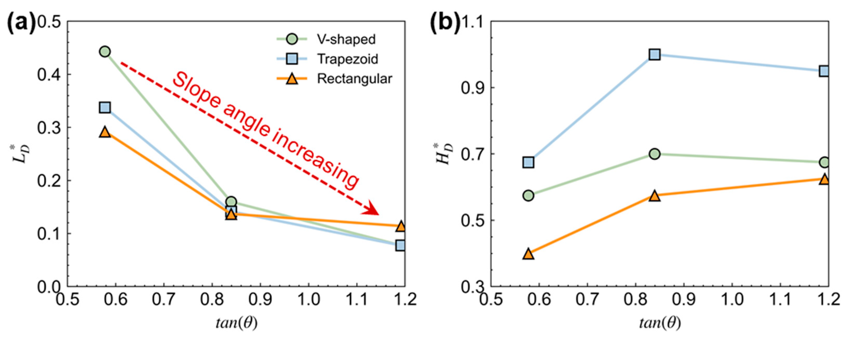
  • Based on numerical results, the dynamics process of flow–slit dam interaction for different-shape cross-sections of the drainage channel, including trapezoid cross-section, V-shaped cross-section, and rectangular cross-section, has been explicitly analyzed and compared. The final pile-up height of trapezoid cross-section is the largest. However, the rectangular cross-section results in a larger final accumulation length;
  • The restraint effect of flume inclined side wall and the buffer effect of dead zone jointly influences the dynamics process of flow–slit dam interaction and the retention efficiency;
  • From the energy evolution aspect, the friction-induced energy loss by inter-particle interaction consumes most of the energy;
  • The cross-section shape of the drainage channel is an important factor that should be considered in the design of barriers, especially the slit dam. The dry granular flow in the drainage channel with a V-shaped cross-section leads to the smallest normal impact force on the slit dam; however, it also intercepts the least particles.
All in all, although a trapezoidal flume is the most straightforward to construct in practical engineering, it exhibits the poorest barrier effect in terms of pile-up height and impact force. Conversely, although the V-shaped one is more challenging to construct, it has the weakest impact force. However, the particle interception efficiency of the V-type is lowest. Therefore, in engineering practice, if considering the damage of the slit dams, the V-type cross-section holds a greater advantage; however, if focusing on the retention efficiency, the rectangular cross-section demonstrates the best effect. Therefore, it is a better measure to use a multi-stage slit dam in engineering practice. For instance, based on the simulation results of this paper, a V-shaped cross-section can be utilized to mitigate the impact force of granular flows, and subsequently, a multi-stage channel interception mode with a rectangular cross-section can be adopted downstream to obstruct the granular flows.

Author Contributions

Conceptualization, J.F. and C.Y.; methodology, J.F.; software, J.F.; validation, C.B.; formal analysis, C.B.; investigation, Y.X.; resources, C.Y.; data curation, G.Z.; writing—original draft preparation, J.F.; writing—review and editing, C.Y.; visualization, J.F.; supervision, C.Y.; project administration, C.Y.; funding acquisition, C.Y. All authors have read and agreed to the published version of the manuscript.

Funding

This research was funded by the National Natural Science Foundation of China (Grant No. U22A20596 and U23A20661).

Institutional Review Board Statement

Not applicable.

Informed Consent Statement

Not applicable.

Data Availability Statement

The data presented in this study are available on request from the corresponding author.

Conflicts of Interest

The authors declare no conflicts of interest.

References

  1. Iverson, R.M. The Physics of Debris Flows. Rev. Geophys. 1997, 35, 245–296. [Google Scholar] [CrossRef]
  2. Iverson, R.M.; Reid, M.E.; Logan, M.; LaHusen, R.G.; Godt, J.W.; Griswold, J.P. Positive Feedback and Momentum Growth during Debris-Flow Entrainment of Wet Bed Sediment. Nat. Geosci. 2011, 4, 116–121. [Google Scholar] [CrossRef]
  3. Iverson, R.M.; George, D.L.; Logan, M. Debris Flow Runup on Vertical Barriers and Adverse Slopes. J. Geophys. Res. Earth Surf. 2016, 121, 2333–2357. [Google Scholar] [CrossRef]
  4. Brighenti, R.; Segalini, A.; Ferrero, A.M. Debris Flow Hazard Mitigation: A Simplified Analytical Model for the Design of Flexible Barriers. Comput. Geotech. 2013, 54, 1–15. [Google Scholar] [CrossRef]
  5. Hungr, O.; Leroueil, S.; Picarelli, L. The Varnes Classification of Landslide Types, an Update. Landslides 2014, 11, 167–194. [Google Scholar] [CrossRef]
  6. Tang, C.; Rengers, N.; van Asch, T.W.J.; Yang, Y.H.; Wang, G.F. Triggering Conditions and Depositional Characteristics of a Disastrous Debris Flow Event in Zhouqu City, Gansu Province, Northwestern China. Nat. Hazards Earth Syst. Sci. 2011, 11, 2903–2912. [Google Scholar] [CrossRef]
  7. Li, S.; Chen, X.; Chen, J.; Tang, H.; You, Y.; Chen, H.; Zhao, W.; Geng, X. Small-Scale Flume Investigation of the Performance of Step-Baffle Drainage Channels in Mitigating Debris Flows. Front. Earth Sci. 2022, 10, 921716. [Google Scholar] [CrossRef]
  8. Chen, H.-X.; Li, J.; Feng, S.-J.; Gao, H.-Y.; Zhang, D.-M. Simulation of Interactions between Debris Flow and Check Dams on Three-Dimensional Terrain. Eng. Geol. 2019, 251, 48–62. [Google Scholar] [CrossRef]
  9. Faug, T.; Caccamo, P.; Chanut, B. A Scaling Law for Impact Force of a Granular Avalanche Flowing Past a Wall. Geophys. Res. Lett. 2012, 39, 23401. [Google Scholar] [CrossRef]
  10. Faug, T. Depth-Averaged Analytic Solutions for Free-Surface Granular Flows Impacting Rigid Walls down Inclines. Phys. Rev. E 2015, 92, 062310. [Google Scholar] [CrossRef] [PubMed]
  11. Albaba, A.; Lambert, S.; Kneib, F.; Chareyre, B.; Nicot, F. DEM Modeling of a Flexible Barrier Impacted by a Dry Granular Flow. Rock Mech. Rock Eng. 2017, 50, 3029–3048. [Google Scholar] [CrossRef]
  12. Song, D.; Zhou, G.G.D.; Xu, M.; Choi, C.E.; Li, S.; Zheng, Y. Quantitative Analysis of Debris-Flow Flexible Barrier Capacity from Momentum and Energy Perspectives. Eng. Geol. 2019, 251, 81–92. [Google Scholar] [CrossRef]
  13. Chen, H.-E.; Chen, T.-Y.; Zheng, Y.-L.; Chiu, Y.-Y.; Chen, S.-C. Optimizing Sediment Control by Adjusting the Relative Spacing between Trusses/Beams in an Open-Type Check Dam. Landslides 2024, 22, 551–565. [Google Scholar] [CrossRef]
  14. Xie, X.; Wang, X.; Liu, Z.; Liu, Z.; Zhao, S. Regulation Effect of Slit-Check Dam against Woody Debris Flow: Laboratory Test. Front. Earth Sci. 2023, 10, 1023652. [Google Scholar] [CrossRef]
  15. Xiong, H.; Hao, M.; Zhao, D.; Qiu, Y.; Chen, X. Study of the Dynamics of Water-Enriched Debris Flow and Its Impact on Slit-Type Barriers by a Modified SPH–DEM Coupling Approach. Acta Geotech. 2023, 19, 1019–1045. [Google Scholar] [CrossRef]
  16. Lei, Y.; Cui, P.; Zeng, C.; Guo, Y. An Empirical Mode Decomposition-Based Signal Process Method for Two-Phase Debris Flow Impact. Landslides 2018, 15, 297–307. [Google Scholar] [CrossRef]
  17. Li, X.; Zhao, J.; Soga, K. A New Physically Based Impact Model for Debris Flow. Géotechnique 2020, 71, 674–685. [Google Scholar] [CrossRef]
  18. Song, D.; Zhou, G.G.D.; Chen, X.Q.; Li, J.; Wang, A.; Peng, P.; Xue, K.X. General Equations for Landslide-Debris Impact and Their Application to Debris-Flow Flexible Barrier. Eng. Geol. 2021, 288, 106154. [Google Scholar] [CrossRef]
  19. Vagnon, F.; Ferrero, A.M.; Alejano, L.R. Reliability-Based Design for Debris Flow Barriers. Landslides 2020, 17, 49–59. [Google Scholar] [CrossRef]
  20. Albaba, A.; Lambert, S.; Faug, T. Dry Granular Avalanche Impact Force on a Rigid Wall: Analytic Shock Solution versus Discrete Element Simulations. Phys. Rev. E 2018, 97, 052903. [Google Scholar] [CrossRef] [PubMed]
  21. Calvetti, F.; di Prisco, C.G.; Vairaktaris, E. DEM Assessment of Impact Forces of Dry Granular Masses on Rigid Barriers. Acta Geotech. 2017, 12, 129–144. [Google Scholar] [CrossRef]
  22. Chen, X.; Cui, P.; You, Y.; Chen, J.; Li, D. Engineering Measures for Debris Flow Hazard Mitigation in the Wenchuan Earthquake Area. Eng. Geol. 2015, 194, 73–85. [Google Scholar] [CrossRef]
  23. Fang, J.; Wang, L.; Hong, Y.; Zhao, J. Influence of Solid–Fluid Interaction on Impact Dynamics against Rigid Barrier: CFD–DEM Modelling. Géotechnique 2021, 72, 391–406. [Google Scholar] [CrossRef]
  24. Li, K.; Wang, Y.-F.; Lin, Q.-W.; Cheng, Q.-G.; Wu, Y. Experiments on Granular Flow Behavior and Deposit Characteristics: Implications for Rock Avalanche Kinematics. Landslides 2021, 18, 1779–1799. [Google Scholar] [CrossRef]
  25. Shen, W.; Li, T.; Li, P.; Lei, Y. Numerical Assessment for the Efficiencies of Check Dams in Debris Flow Gullies: A Case Study. Comput. Geotech. 2020, 122, 103541. [Google Scholar] [CrossRef]
  26. Gong, S.; Zhao, T.; Zhao, J.; Dai, F.; Zhou, G.G.D. Discrete Element Analysis of Dry Granular Flow Impact on Slit Dams. Landslides 2021, 18, 1143–1152. [Google Scholar] [CrossRef]
  27. Kong, Y.; Guan, M.; Li, X.; Zhao, J.; Yan, H. How Flexible, Slit and Rigid Barriers Mitigate Two-Phase Geophysical Mass Flows: A Numerical Appraisal. J. Geophys. Res. Earth Surf. 2022, 127, e2021JF006587. [Google Scholar] [CrossRef]
  28. Li, N.; Zhou, G.G.D.; Hu, H.; Cui, K.F.E.; Huang, Y. Influence of Trapping Efficiency on the Pile-up Geometry of Granular Flows behind Slit Dams. Eng. Geol. 2023, 326, 107333. [Google Scholar] [CrossRef]
  29. Marchelli, M.; Leonardi, A.; Pirulli, M.; Scavia, C. On the Efficiency of Slit-Check Dams in Retaining Granular Flows. Géotechnique 2020, 70, 226–237. [Google Scholar] [CrossRef]
  30. Ren, S.; Zhang, P.; Man, T.; Galindo-Torres, S.A. Numerical Assessments of the Influences of Soil–Boulder Mixed Flow Impact on Downstream Facilities. Comput. Geotech. 2023, 153, 105055. [Google Scholar] [CrossRef]
  31. Choi, C.E.; Goodwin, G.R.; Ng, C.W.W.; Cheung, D.K.H.; Kwan, J.S.H.; Pun, W.K. Coarse Granular Flow Interaction with Slit Structures. Géotechnique Lett. 2016, 6, 267–274. [Google Scholar] [CrossRef]
  32. Goodwin, G.R.; Choi, C.E. Slit Structures: Fundamental Mechanisms of Mechanical Trapping of Granular Flows. Comput. Geotech. 2020, 119, 103376. [Google Scholar] [CrossRef]
  33. Hu, H.; Zhou, G.G.D.; Song, D.; Cui, K.F.E.; Huang, Y.; Choi, C.E.; Chen, H. Effect of Slit Size on the Impact Load against Debris-Flow Mitigation Dams. Eng. Geol. 2020, 274, 105764. [Google Scholar] [CrossRef]
  34. Chen, Z.; Rickenmann, D.; Zhang, Y.; He, S. Effects of Obstacle’s Curvature on Shock Dynamics of Gravity-Driven Granular Flows Impacting a Circular Cylinder. Eng. Geol. 2021, 293, 106343. [Google Scholar] [CrossRef]
  35. Choi, C.E.; Ng, C.W.W.; Law, R.P.H.; Song, D.; Kwan, J.S.H.; Ho, K.K.S. Computational Investigation of Baffle Configuration on Impedance of Channelized Debris Flow. Can. Geotech. J. 2015, 52, 182–197. [Google Scholar] [CrossRef]
  36. Fang, Y.; Liu, H.; Guo, L.; Li, X. Model Experiment Exploration of the Kinetic Dissipation Effect on the Slit Dam with Baffles Tilted in the Downstream Direction. Water 2022, 14, 2772. [Google Scholar] [CrossRef]
  37. Kim, B.-J.; Yune, C.-Y. Flume Investigation of Cylindrical Baffles on Landslide Debris Energy Dissipation. Landslides 2022, 19, 3043–3060. [Google Scholar] [CrossRef]
  38. Li, S.; Wang, J.; Wang, F.; Li, P. Experimental Study on a Debris Flow Water-Sediment Separation Structure of a Funnel-Type Grating and Its Sorting Characteristics. Bull. Eng. Geol. Environ. 2023, 82, 148. [Google Scholar] [CrossRef]
  39. Shima, J.; Moriyama, H.; Kokuryo, H.; Ishikawa, N.; Mizuyama, T. Prevention and Mitigation of Debris Flow Hazards by Using Steel Open-Type Sabo Dams. Int. J. Eros. Control Eng. 2016, 9, 135–144. [Google Scholar] [CrossRef]
  40. Choi, C.E.; Ng, C.W.W.; Song, D.; Kwan, J.H.S.; Shiu, H.Y.K.; Ho, K.K.S.; Koo, R.C.H. Flume Investigation of Landslide Debris–Resisting Baffles. Can. Geotech. J. 2014, 51, 540–553. [Google Scholar] [CrossRef]
  41. Leonardi, A.; Goodwin, G.R.; Pirulli, M. The Force Exerted by Granular Flows on Slit Dams. Acta Geotech. 2019, 14, 1949–1963. [Google Scholar] [CrossRef]
  42. You, Y.; Pan, H.; Liu, J.; Ou, G. The Optimal Cross-Section Design of the “Trapezoid-V” Shaped Drainage Canal of Viscous Debris Flow. J. Mt. Sci. 2011, 8, 103–107. [Google Scholar] [CrossRef]
  43. Jiang, Y.-J.; Towhata, I. Experimental Study of Dry Granular Flow and Impact Behavior Against a Rigid Retaining Wall. Rock Mech. Rock Eng. 2013, 46, 713–729. [Google Scholar] [CrossRef]
  44. Jiang, Y.-J.; Fan, X.-Y.; Li, T.-H.; Xiao, S.-Y. Influence of Particle-Size Segregation on the Impact of Dry Granular Flow. Powder Technol. 2018, 340, 39–51. [Google Scholar] [CrossRef]
  45. Zhou, G.G.D.; Du, J.; Song, D.; Choi, C.E.; Hu, H.S.; Jiang, C. Numerical Study of Granular Debris Flow Run-up against Slit Dams by Discrete Element Method. Landslides 2020, 17, 585–595. [Google Scholar] [CrossRef]
  46. Shen, W.; Zhao, T.; Zhao, J.; Dai, F.; Zhou, G.G.D. Quantifying the Impact of Dry Debris Flow against a Rigid Barrier by DEM Analyses. Eng. Geol. 2018, 241, 86–96. [Google Scholar] [CrossRef]
  47. Nie, Y.-P.; Wang, X.-K.; Yan, X.-F. CFD-DEM-Based Evaluation of Main-Channel Sediment Transport Processes Subject to Supplement from a Steep Tributary. Eng. Geol. 2024, 333, 107498. [Google Scholar] [CrossRef]
  48. Piton, G.; Recking, A. Design of Sediment Traps with Open Check Dams. I: Hydraulic and Deposition Processes. J. Hydraul. Eng. 2016, 142, 04015045. [Google Scholar] [CrossRef]
  49. Rossi, G.; Armanini, A. Impact Force of a Surge of Water and Sediments Mixtures against Slit Check Dams. Sci. Total Environ. 2019, 683, 351–359. [Google Scholar] [CrossRef] [PubMed]
  50. Jiang, Y.-J.; Zhao, Y.; Towhata, I.; Liu, D.-X. Influence of Particle Characteristics on Impact Event of Dry Granular Flow. Powder Technol. 2015, 270, 53–67. [Google Scholar] [CrossRef]
Figure 1. Schematic diagram of DEM calibration from Jiang and Towhata [43].
Sustainability 17 01649 g001
Figure 2. Impact process of granular flow obtained from (a–e) flume tests in Jiang and Towhata [43] and (a1–e1) DEM simulation in this study.
Sustainability 17 01649 g002
Figure 3. Evolutionary behaviors of impact force obtained by flume tests in Jiang and Towhata [43] and DEM simulation in this study.
Sustainability 17 01649 g003
Figure 4. Layout of cross-section shape of drainage channel: (a) V-shaped cross-section, (b) trapezoid cross-section, and (c) rectangular cross-section.
Sustainability 17 01649 g004
Figure 5. Simulation results showing the interaction between granular flow and the slit dam for different cross-section shapes of the drainage channel: (a1a4) V-shaped cross-section, (b1b4) trapezoid cross-section, and (c1c4) rectangular cross-section. The slope angle is 40°.
Sustainability 17 01649 g005
Figure 6. The final deposition morphology of the dead zones for different cross-section shapes of the drainage channel: (a1,a2) V-shaped cross-section, (b1,b2) trapezoid cross-section, and (c1,c2) rectangular cross-section. The slope angle is 40°.
Sustainability 17 01649 g006
Figure 7. Normalized deposition morphology parameters: (a) the normalized final accumulation length L D * and (b) the normalized final accumulation height H D * .
Sustainability 17 01649 g007
Figure 8. The evolution of average velocity of granular flows with time: (a) different slope angle of trapezoid cross-section type, (b) θ = 30 ° , (c) θ = 40 ° , (d) θ = 50 ° .
Sustainability 17 01649 g008
Figure 9. Evolution of the retention efficiency under (a) different slope angles of trapezoid cross-section type, (b) θ = 30 ° , (c) θ = 40 ° , (d) θ = 50 ° .
Sustainability 17 01649 g009
Figure 10. Effect of the angle of slope and cross-section type on the retention efficiency.
Sustainability 17 01649 g010
Figure 11. Typical time–history curve of the normal impact force on the slit dam: (a) different slope angle of trapezoid cross-section type, (b) θ = 30 ° , (c) θ = 40 ° , (d) θ = 50 ° .
Sustainability 17 01649 g011
Figure 12. Peak normal impact force acting on the slit dam for different cross-section shapes of drainage channel under different slope angles.
Sustainability 17 01649 g012
Figure 13. Energy consumption during the interaction process between granular flow and the slit dam for the drainage channel with rectangular-shaped cross-section of β = 40°.
Sustainability 17 01649 g013
Table 1. Properties of materials.
Material Density   ρ s k g / m 3 Poisson s   Ratio   υ Young s   Modulus   E M P a
Particles25500.25100
Flume79000.32 × 103
Barrier79000.32 × 103
Table 2. Contact parameters.
ParameterParticle–ParticleParticle–Flume BaseParticle–Slide WallParticle–Barrier
Contact modelHertz–Mindlin (no slip)
Coefficient of restitution e 0.60.60.60.6
Friction coefficient μ f 1.330.4660.2680.384
Rolling friction coefficient μ r 0.060.010.010.01
Table 3. Test plans of flow–slit dam interaction.
Test Series Slope   Angle / ( ° ) Cross-Section Shape Particle   Diameter / m m Initial   Deposition   Volume / L
1–5 30 ° , 40 ° , 50 ° V-shaped1039.6
6–10 30 ° , 40 ° , 50 ° Trapezoid1039.6
11–15 30 ° , 40 ° , 50 ° Rectangular1039.6
1–5 30 ° , 40 ° , 50 ° V-shaped1039.6
Disclaimer/Publisher’s Note: The statements, opinions and data contained in all publications are solely those of the individual author(s) and contributor(s) and not of MDPI and/or the editor(s). MDPI and/or the editor(s) disclaim responsibility for any injury to people or property resulting from any ideas, methods, instructions or products referred to in the content.

